1. Introduction
Strain sensors have different applications in engineering, industry, and medicine, which are vital in measuring parameters such as stress, strain, pressure, and vibration. These sensors transform mechanical deformation into electrical signals, often resulting in alterations in capacitance or resistance [
1]. Wearable electronic devices designed to withstand high strain exhibit remarkable stretchability and excellent adherence to the skin. This characteristic enables the monitoring of vital signs and human health. Notably, stretchable strain sensors exemplify wearable electronic devices capable of detecting body movements and monitoring vital signs such as blood pressure, pulse rate, and body temperature. These strain sensors are also compatible with human skin. The demand for highly stretchable sensors that can be comfortably worn and integrated into the skin is particularly pronounced in domains such as rehabilitation, personal health monitoring, sports performance tracking, robotics, and entertainment technologies (e.g., motion capture for games and animations) [
2].
While conventional strain sensors like semiconductor and metallic strain sensors possess commendable properties such as well-established and cost-effective technology, they also exhibit limitations, including a restricted measurement range, low sensitivity, material structure issues, limited fatigue life, and sensitivity to environmental conditions [
3]. Indeed, the strain sensitivity of commercial strain sensors is considerably low owing to the materials employed in their construction. Consequently, the limitations associated with these sensors have spurred an increased utilization of new smart materials such as doped silicon, nanoparticles, nanowires, graphene, and carbon nanotubes (CNTs) [
4]. Among these materials, CNTs, discovered by Iijima in 1991, have emerged as highly versatile substances extensively employed across diverse fields due to their unique mechanical, electrical, thermal, and chemical properties. Leveraging the exceptional properties of CNTs, researchers have successfully developed a novel strain sensor type that surpasses the performance limitations of conventional metallic strain sensors. The remarkable properties of CNT composites make them highly desirable materials for diverse fields such as electronics, energy, biomedicine, and aerospace [
5].
Carbon-nanotube-based sensors are prized for their wide-ranging applications and exceptional inherent properties. These include impressive mechanical strength, electrical conductivity, and thermal stability due to the unique single-carbon atom bonds within CNTs. Instead of being used alone, CNTs shine in polymer/CNT nanocomposites (polymers such as polyaniline, known for its exceptional conductivity), enhancing thermal, mechanical, and barrier traits. This synergy yields cost-effective, highly sensitive piezoresistive sensors. Within these nanocomposites, CNTs serve as both reinforcement and conductivity contributors. The coating of surfaces with these nanotubes forms versatile sensing layers suitable for various applications [
6,
7].
CNT composites comprise two distinct phases: a polymer matrix in the first phase and CNTs as the reinforcing agent in the second phase. CNTs, typically in the nanoscale range with a high aspect ratio, form clusters and agglomerate [
8]. However, uniform dispersion can be achieved by effectively separating and dispersing these clusters into individual elements. Numerous methods, such as solution casting, melt blending, and localized polymerization, have successfully prepared CNT composites, producing nanocomposites with excellent physical properties like electrical conductivity, strength, elasticity, and mechanical properties [
9]. The distribution of CNTs within the polymer matrix plays a pivotal role in determining these composites’ overall performance and application potential, posing a significant challenge for researchers [
10].
Key factors for achieving optimal performance include effective surface bonding, uniform distribution of CNTs, alignment, and prevention of agglomeration. To enhance the strength of CNT-based composites, preventing aggregation is crucial. This can be achieved by ultrasonication of the nanocomposite solution [
11]. The properties of these composites are influenced by factors such as the weight percentage of CNTs, their orientation, and the bond formed between CNTs and the polymer matrix [
12]. Two methods have been employed to fabricate these nanocomposites: non-covalent bonding and covalent bonding. In the case of non-covalent bonding, CNTs are directly incorporated within the polymer matrix, while localized polymerization creates covalent bonds on the surface [
13]. CNTs and polymers can interact through state transition reactions or non-covalent bonding with specific polymers [
14].
Nanocomposites’ properties heavily rely on CNTs’ distribution within the polymer matrix. Considering CNTs are often dispersed randomly within the polymer matrix, extensive research has been conducted to achieve a directed and uniform distribution of CNTs. However, effectively dispersing CNTs within a polymer matrix presents challenges [
15,
16]. Furthermore, the connection between CNTs and polymers in composites, as well as related measurements, necessitates further advancements and refinement. Numerous methods have been explored to achieve efficient distribution and dispersion of CNTs within composites, including ultrasound homogenization and sonication [
17].
Polymer/CNT composites exhibit superior mechanical properties and enhanced sensitivity compared to pure polymers. Polymer/CNT strain sensor measurement ranges vary depending on the type of polymers utilized. CNTs are found utility in a wide range of polymer matrices, including poly (methyl methacrylate), polydimethylsiloxane, polystyrene, polypropylene, nylon-6, polyaniline (PANI), polyethylene, polyurethane, epoxy resin, polyvinyl alcohol, and others [
18,
19,
20].
The production of polymer/CNT composites varies depending on whether the polymer is of the thermoset or thermoplastic type. Mixing and hot-pressing techniques have been proposed for melting thermoplastic polymers [
21]. At the same time, localized polymerization is often employed for elastomers and thermosets, facilitating strong adhesion between CNTs and the polymer [
22]. The coating of composites commonly employs pattern casting and printing techniques on the target surface. Layer-by-layer technology has also been implemented in certain studies [
23]. Polymer/elastomer composites exhibit higher conductivity than thermoplastic and thermoset composites with the same concentration of CNTs. Mechrez et al. reported an electrical conductivity of up to 1000 S/cm for polyacrylate containing 10% by weight of CNTs [
24]. Chen et al. achieved a conductivity of 280 S/cm for randomly distributed multi-walled CNTs in polydimethylsiloxane at a weight percentage of 1.3% [
25]. CNTs embedded in thermoset and thermoplastic matrices with the same concentration exhibit a conductivity range of 0.1 to 50 S/cm [
24].
The sensitivity of nanocomposites can be predicted by measuring the viscosity of the dispersed material, a phenomenon that can be harnessed to create highly sensitive strain sensors [
26]. In the pursuit of high sensitivity, a high electrical conductivity in the saturation region is not advantageous. According to a study by Ramasubramaniam et al. on polyphenylene ether/CNT single-walled composites, the most heightened sensitivity is achieved within an electrical conductivity range of 0.1 S/m to 10 S/m [
27].
In our previous work, we introduced a novel and cost-effective approach for fabricating a sensitive and flexible interdigitated capacitive strain sensor based on carbon nanofiber/PANI/silicone rubber nanocomposite, achieving a high gauge factor of around 14 under 2% applied strain and 2.8 for 20% applied strain [
28]. This work focuses on designing and fabricating flexible strain sensors using CNT/polymer nanocomposites for body movement monitoring. The agglomeration issue of CNTs is addressed through a dispersion synthesis method, while aniline enhances mechanical strength and electrical conductivity. Two types of strain sensors are created: CNTs/PANI and CNTs/PANI/silicone rubber. Rectangular designs are implemented using cost-effective methods like thick adhesive and lithography. Printed circuit boards (PCBs) were used as substrates, enabling low-cost and accurate fabrication. This research also involves the simulation of CNT and PANI interactions using LAMMPS software and determining optimal CNT to PANI ratios, then obtaining stress–strain curves. We showed that using CNT/PANI material in strain sensors demonstrates favorable properties, such as a high gauge factor, stability, low resistance, and sensitivity to strain.
A noteworthy distinction of our work lies in the inclusion of silicone rubber within the composite matrix. This addition not only imparts mechanical flexibility to the sensor but also introduces a dynamic doping effect that enhances electrical conductivity under strain conditions. This innovative aspect differentiates our approach from conventional fabrication routes, and it contributes to the exceptional performance of the resulting strain sensors.
Comparative analysis of our strain sensors with existing fabrication methods, such as those discussed in Poompiew et al. [
29], Niranjan et al. [
30], and ur Rehman et al. [
31], reveals distinct advantages in terms of gauge factors, and potential applications. Our fabricated strain sensors demonstrate superior gauge factors of 144.5 and 167.94 for composite configurations of MWCNT/PANI and MWCNT/PANI/silicone rubber, respectively. This significant enhancement in gauge factor surpasses the values reported by Poompiew et al., highlighting the effectiveness of our composite design. Furthermore, the dynamic doping effect facilitated by the silicone rubber component sets our approach apart from the solvent-casting method employed by Niranjan et al. and the in situ polymerization technique utilized by ur Rehman et al.
2. Materials and Methods
2.1. Materials
To obtain excellent electrical and mechanical properties, we incorporated CNTs in a robust polymer matrix of PANI, known for its exceptional conductivity, and silicone rubber to enhance the composite’s stretchability. The CNTs used in the study were multi-walled with a purity level exceeding 95% and a surface area of 450 m2/g obtained from Platonic Nanotech (US Research Nanomaterials, Inc., Houston, TX, USA). Other materials, including aniline with a purity of more than 99.5%, ammonium peroxoydisulfate (assay ≥ 98.0% (iodometric)), nitric acid (ACS reagent, ≥90.0%), sulfuric acid (assay 99.999%), and hydrochloric acid 37%, were obtained from Merck (Merck Pte. Ltd., Darmstadt, Germany).
2.2. CNTs Functionalization
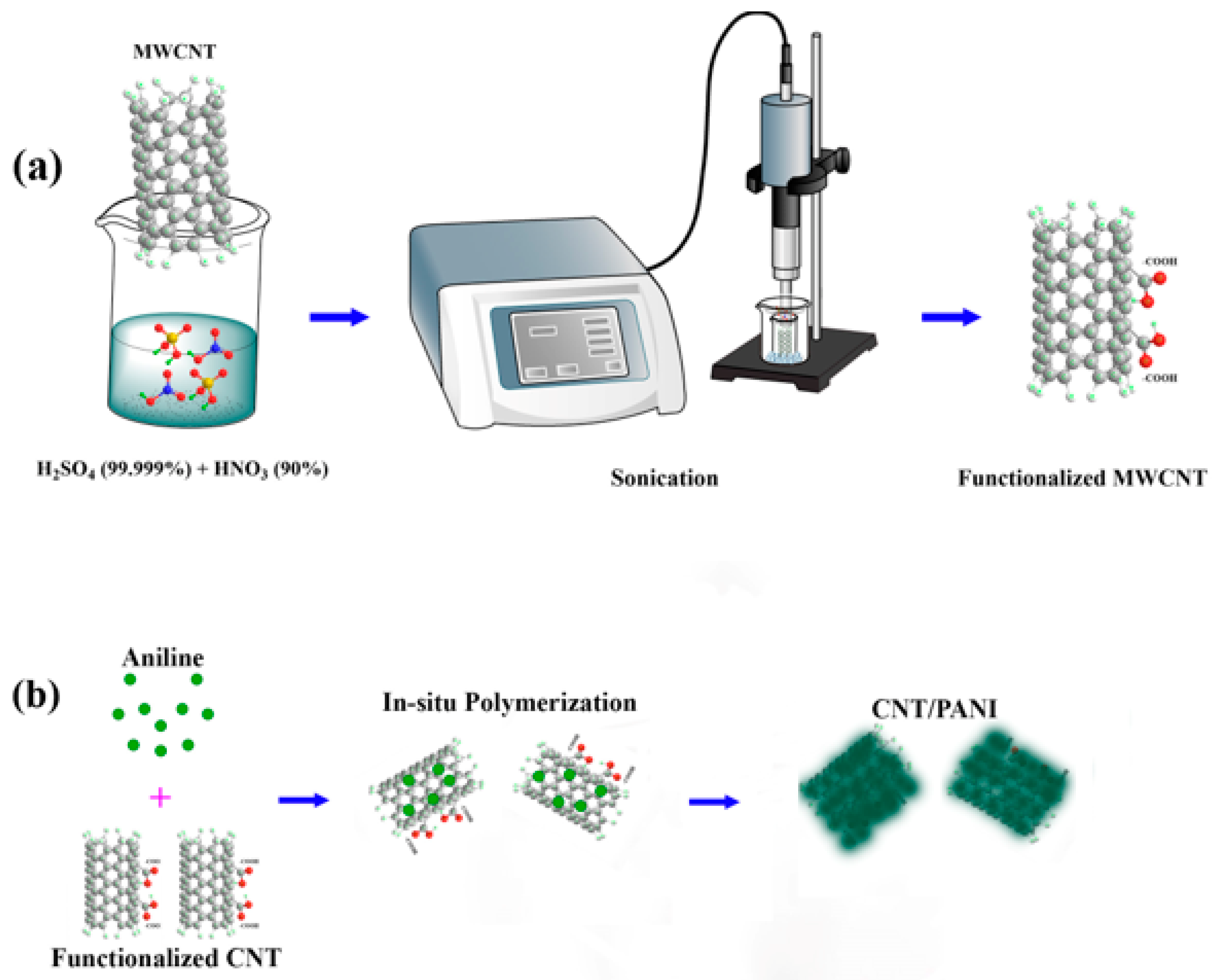
Considering that CNTs, in their non-functional state, lack a propensity for bond formation, we functionalized them to liberate their outer surface bonds. The functionalization process was undertaken sequentially to introduce COOH groups to the CNTs, as illustrated schematically in
Figure 1a. The process of functionalizing multi-walled carbon nanotubes (MWCNTs) was conducted using the following procedure: a mixture of HNO
3 and H
2SO
4 is prepared in a 2:3 ratio, resulting in a solution with a total volume of 250 mL. Subsequently, 50 mg of pristine MWCNTs is added to this solution. Ultrasonic treatment is employed in an ice bath to separate entangled nanotubes and enhance their interaction with the solution. The solution is pulsed in 3-s intervals to prevent the breaking of CNTs. After ultrasonic treatment, the mixture is subjected to vigorous magnetic stirring for periods of 18 h at room temperature [
32].
2.3. Synthesis of CNTs with PANI
In situ chemical polymerization was performed by combining aniline with dispersed functionalized CNTs to create the CNT and PANI composite. Functionalized CNTs were uniformly dispersed in 20 mL HCl through ultrasonication for an hour. The resulting suspension was cooled in an ice bath to maintain a 0 °C temperature.
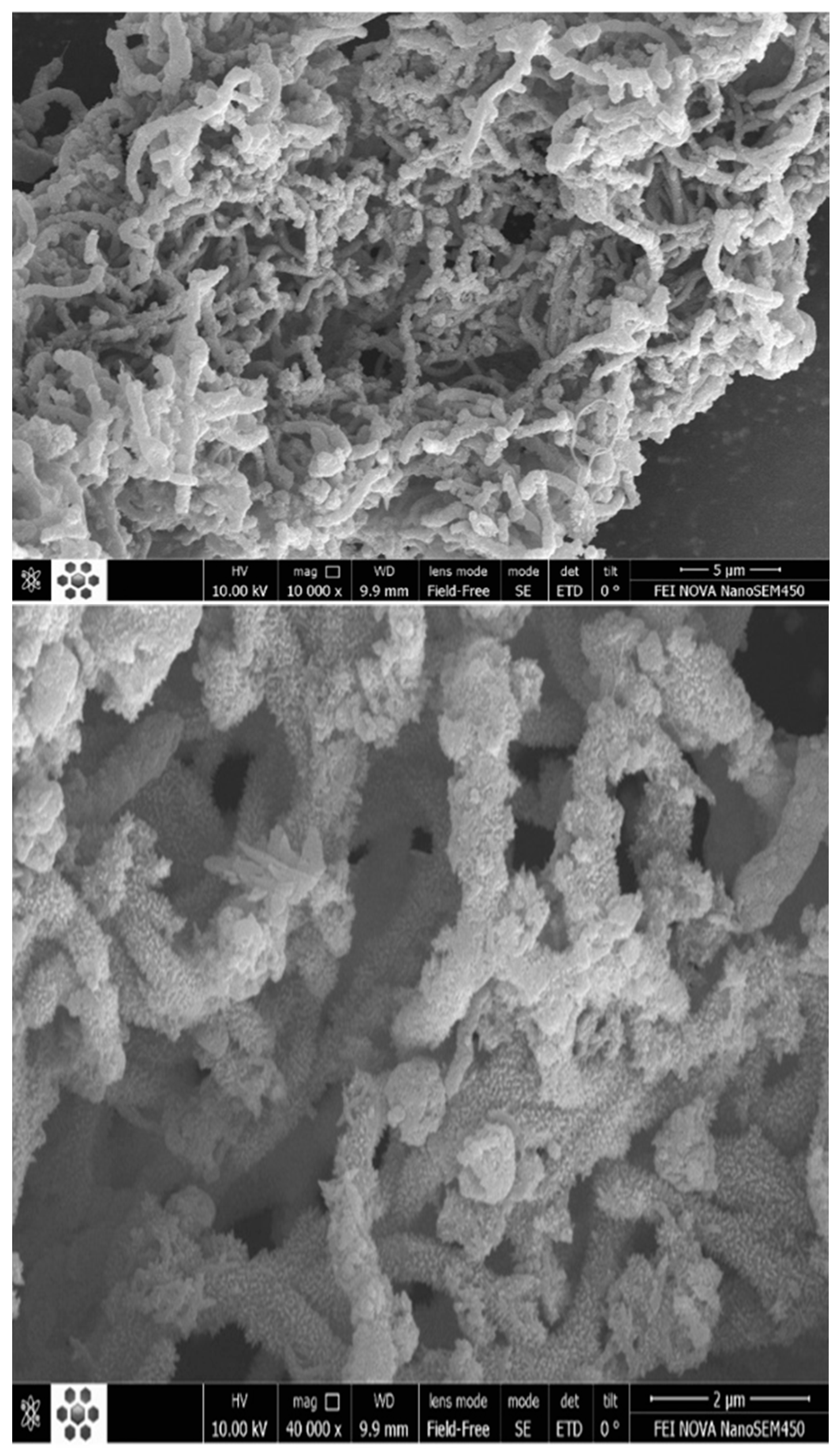
Subsequently, 1 mL of aniline monomer was gradually added to the stirred CNT suspension. A solution containing 2 g of ammonium peroxoydisulfate (APS) dissolved in 20 mL water was then introduced. The suspension’s color changed from dark to green, indicating successful polymerization initiation. The reaction continued for 8 h with stirring in an ice bath. The resulting dark green material was washed with deionized water and acetone to remove unreacted components. After filtering, the material was vacuum-dried at 80 °C overnight to obtain the dry CNT/PANI composite [
33]. A schematic of the process of in situ polymerization can be seen in
Figure 1b, and
Figure 2 presents SEM images of PANI-coated CNTs.
2.4. Fabrication of Strain Sensors
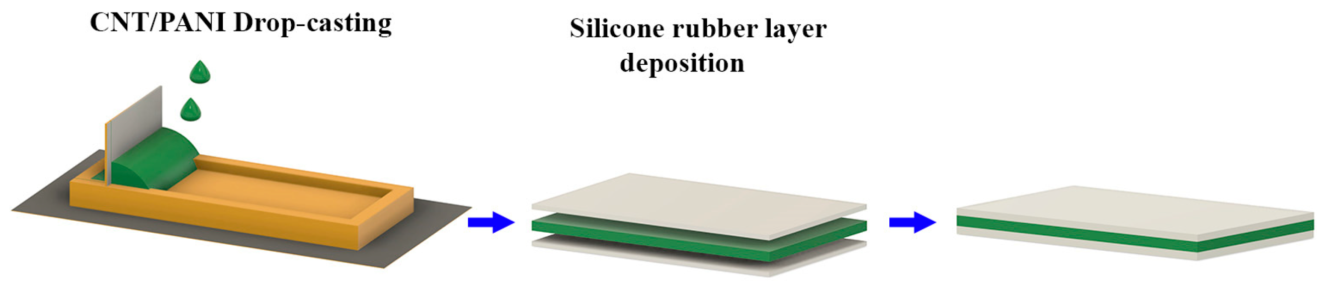
Two molding methods were utilized to create the sensors. The first method involved the application of thick adhesives to form rectangular patterns on the desired substrate, followed by a deposition process to fabricate the strain sensors. In the second method, photolithography generated a rectangular pattern on a copper layer of a printed circuit board (PCB), serving as a mold for the strain sensor. The first method is fabricating strain sensors using CNT and PANI materials (
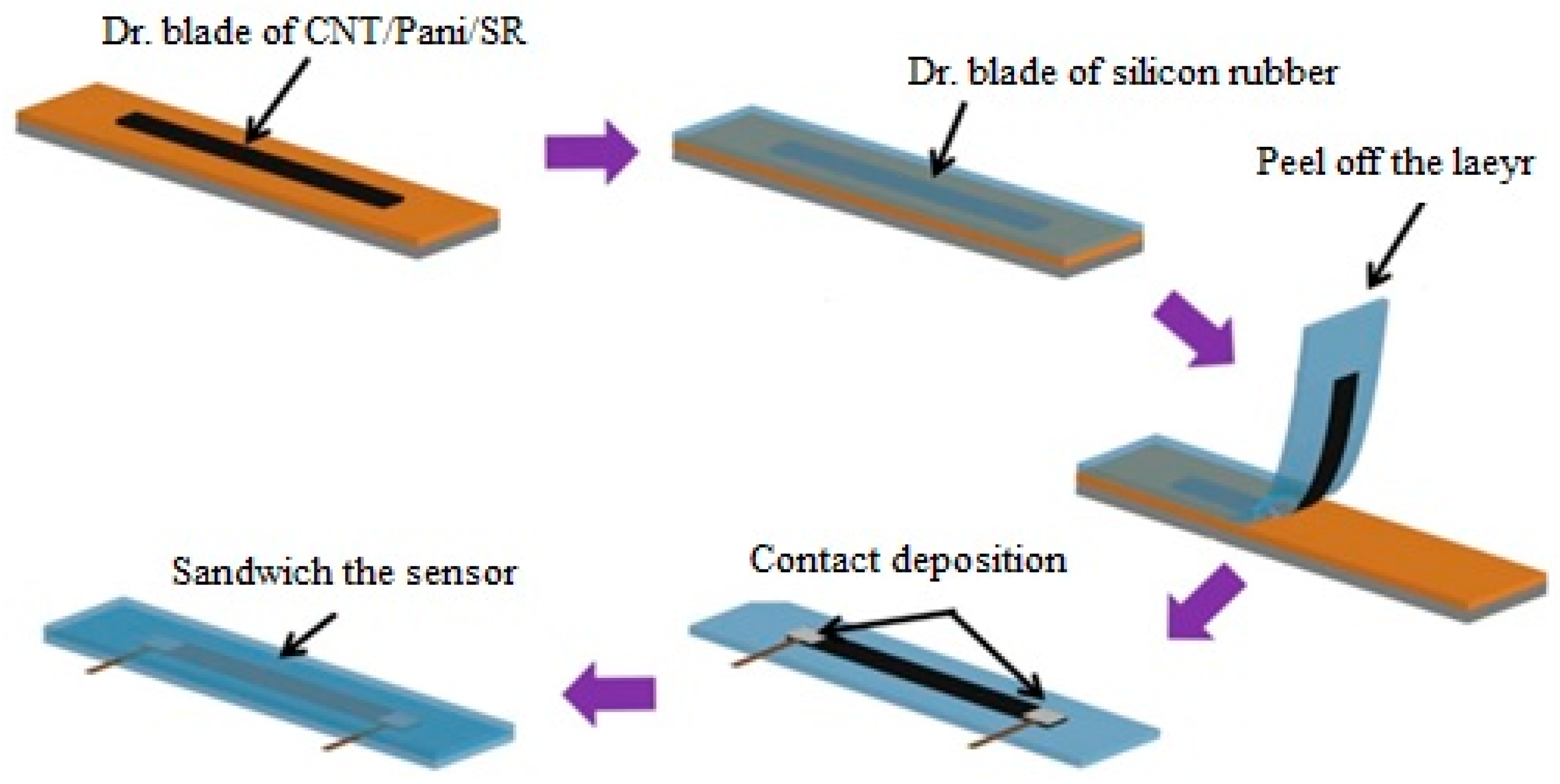
Figure 3). In contrast, the second method was employed for strain sensors utilizing CNT/PANI/silicone rubber materials (
Figure 4). In this case, the lithography method was used to create the strain sensor mold.
To construct a strain sensor based on CNT/PANI, a layer of the CNT/PANI material is drop-cast onto a mold (
Figure 3). The resulting strain sensor is then affixed onto a fabric. A thin silicone rubber layer is placed on top to strengthen it further, effectively sandwiching the strain sensor.
In the second method, the material is poured into copper molds to fabricate strain sensors from CNT/PANI/silicone rubber, as shown in
Figure 4, and excess material is removed using the blading method. Subsequently, the fabric is glued onto the material and held in place for a few hours. After separation from the mold, the strain sensor adheres well to the fabric surface due to the presence of silicone rubber. We utilized sputtering as the method to fabricate the gold connection pads, and to establish an electrical connection, we affixed conductive copper onto the connection pads using carbon adhesive. Finally, a protective layer was applied as a final step. In light of the well-documented toxicity concerns associated with carbon nanotubes (CNTs) when inhaled or exposed to biological systems, the encapsulation of the CNT/PANI strain sensor with silicone rubber emerges as a crucial safety measure. This encapsulation serves as a robust physical barrier, effectively containing the CNTs within the sensor structure. By doing so, it mitigates the potential risks of CNT release into the environment or direct contact with the skin during wearable or skin-mountable applications. This protective encapsulation significantly reduces health and safety concerns related to potential CNT exposure.
2.5. Strain Resistance Test Setup
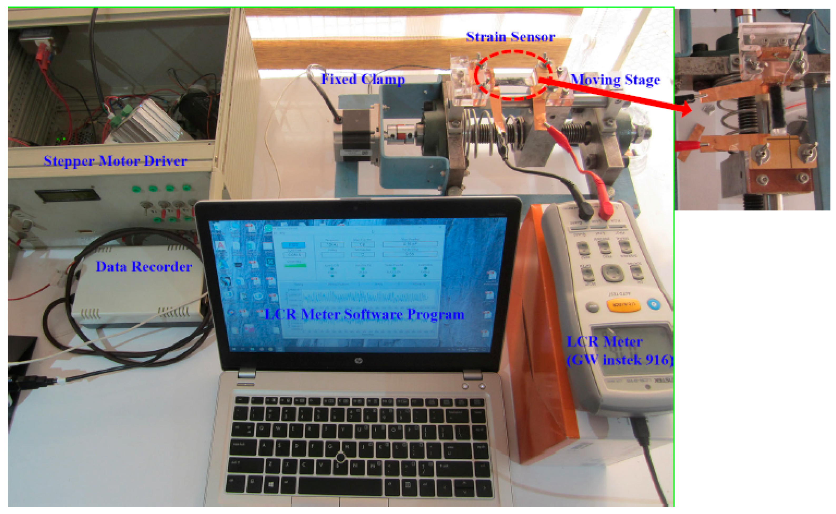
The strain sensor’s performance parameters were evaluated using a designed test setup. Electrical connections between the sensor’s connection pads and an LCR meter (inductance (L), capacitance (C), and resistance (R)) (GW Instek 916) were established by securing the pads to two clamps with electrical terminals. One clamp remained stationary, while the other clamp was connected to a lead screw, which received commands from a stepper motor driver (
Figure 5). During the application of strain, a software program associated with the LCR meter was utilized to plot the resistance change graph. The setup allowed for adjusting various parameters such as strain rate, speed of the movable clamp, and the number of cycles. By employing this setup, precise control over the testing conditions was achieved. The acquired data were subsequently imported into MATLAB software, enabling the extraction of performance parameters for the strain sensor.
2.6. Gauge Factor
The gauge factor is a parameter that indicates the sensitivity of a strain gauge. The slope of the relative change in the electrical signal (resistance) with respect to the applied strain represents the strain sensor’s gauge factor. As mentioned, the performance and efficiency of a strain gauge are determined by the gauge factor, which is calculated using Equation (1).
In Equation (1),
is the symbol representing changes in resistance,
is the resistance of the specimen,
represents the changes in length, and l is the length of the specimen. Therefore, strain sensors based on carbon nanotubes must inherently possess good electrical conductivity. For this reason, studying the electrical conductivity of CNT/polymer nanocomposites is of great significance [
34].
2.7. Simulation with LAMMPS Software
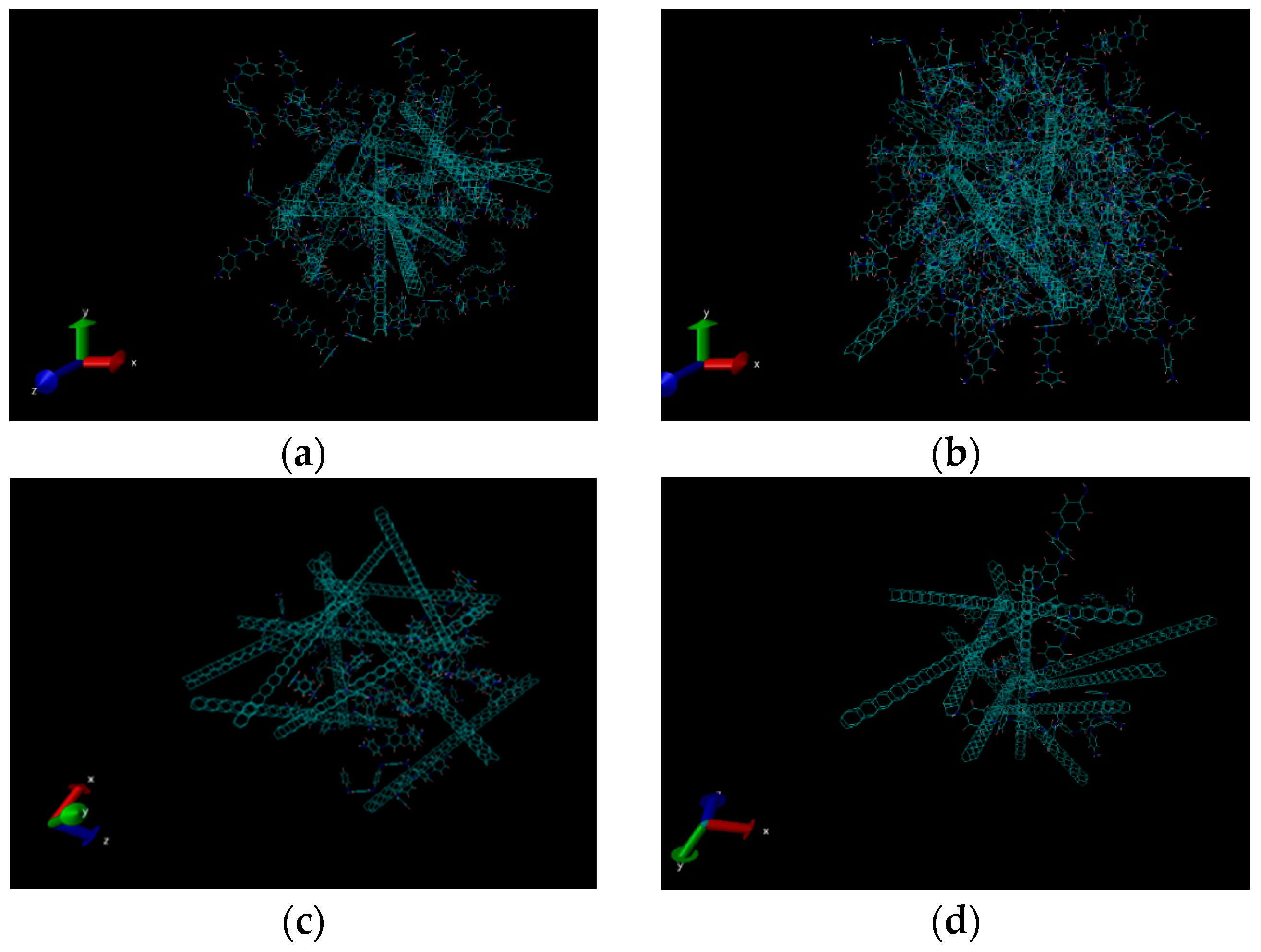
Designing and implementing structures composed of CNTs without knowledge of their mechanical properties, such as load-bearing capacity and elastic behavior range, is impractical. The introduction of polymer materials significantly alters the behavior of CNT. Understanding the range of behavior changes in these materials is crucial for their sensor utilization. While it is challenging to provide precise mechanical parameter values for CNT due to variations in synthesis methods, knowledge of the boundary conditions can assist in selecting appropriate methods and materials. This study utilized polymerized CNTs to enhance their sensing properties in an electromechanical system involving mechanical strains and electrical signals.
The mechanical properties and stress–strain diagrams of CNT/PANI structures with different percentage ratios of these two components were simulated at three different temperatures using LAMMPS software. The aim was to estimate the range of Young’s modulus, temperature, and percentage composition of CNT/PANI under laboratory conditions and determine the relevant parameters. The simulations were performed at temperatures of 300, 325, and 350 Kelvin by considering the diameter and chirality of the CNTs used in the simulation. Different weight ratios of CNT to PANI (20/80, 40/60, 60/40, and 80/20) were investigated.
The loading method was employed in the simulation, where tension is applied to the simulated structure to calculate the stress–strain curve and extract mechanical information at room temperature. In this method, the initial length of the structure is determined based on the number of atoms present in the simulation. Then, tension is applied to the structure in one direction and the strain value is calculated using the instantaneous length of the structure in the strain formula. The simulated structure’s stress–strain curve is obtained by loading or applying subsequent time steps in the structure code. The maximum stress the material can sustain with reversible deformation is obtained against the strain for CNT/PANI structures with varying weight ratios to identify the elastic region.
The simulation of a CNT/PANI relies on the loading and deform command to calculate mechanical properties. The stress–strain diagram is determined by subjecting the simulated structure to tension, and the mechanical information is derived from it. The simulation process involves several steps, including preparing the simulation system, defining the positions of the atoms, specifying potentials and settings for the simulated system, applying deformation (tension) and loading to different structures, and performing calculations related to estimating the stress–strain diagram.
The first part focuses on the initial conditions and preparations for the simulation, such as determining the unit used for physical quantities, simulation dimensions, boundary conditions, and the structure of the smallest simulation building blocks. The second part provides the code for defining the atomic structure of interest using the “read-data” command in the upcoming simulation codes. In the third part, commands like “pair-style”, “bond-style”, and “angle-style” are employed to select the type and formulation of interatomic interactions used in calculating mechanical properties. The corresponding coefficients for the atoms in the simulation are defined using the “coeff” command, which relies on two references provided for interatomic potentials [
35,
36]. The “thermos” command also displays thermodynamic outputs in the software output at specified time intervals, set to 1000 time steps using the “timestep” command. The atoms in the simulation are assigned a velocity corresponding to room temperature using the “velocity” command. The simulated system is then equilibrated with the NPT or NVE thermostat for specific time steps using the “fix” command to stabilize fluctuations.
Next, the simulation calculated the initial length of the structure before loading using the “variable” command, as the stress–strain curve formula requires the initial length. The subsequent step involves applying tension and deformation to the sample. Firstly, the previously used hinge is canceled using the “unfix” command, and then the “fix” command is employed to select the “npt” hinge for mechanical calculations. Using the “deform” command, stress is applied to the system in its initial state, and the necessary physical quantities for calculating the stress–strain curve of the simulated system are determined. These quantities, including the simulation time step, stress, and strain of the entire simulated structure, are calculated in the final step (step five). Finally, the required parameters for plotting the stress–strain diagram are obtained through the loading method, and these quantities are calculated and printed at intervals of 10 time steps.
4. Discussion
The presented research focused on investigating the mechanical and electrical properties of CNT/PANI nanocomposites for potential application as strain sensors. The results of the molecular dynamics simulations provided insights into the mechanical behavior of the CNT/PANI samples under different weight ratios and temperatures. The findings indicate a complex interaction between the components’ proportions and their mechanical response.
The stress–strain graphs shown in
Figure 7a clearly present the effect of varying PANI weight ratios on the composite’s behavior. Increasing PANI content led to a decrease in the elastic region and load-bearing capacity, while a weight ratio of 40/60 (CNT/PANI) resulted in plastic behavior at higher strains. This result underscores the importance of carefully selecting the weight percentage of PANI and CNT to achieve the desired mechanical characteristics. The selection of the 40/60 weight ratio for CNT/PANI composites as the optimum one is considered to balance mechanical behavior and conductivity.
Temperature effects were investigated by examining CNTs across a temperature range of 300 K to 350 K (
Figure 7b). The results revealed that temperature fluctuations had an impact on yield behavior and Young’s modulus of the composite, while it remained insignificant for stress levels below 1%. This implies that the selected temperature range does not significantly compromise the material’s structural stability under practical conditions.
Through electron microscopy imaging, it has been confirmed that the functionalization of CNTs and the deposition of PANI on their surfaces were successful. The porous nature of the PANI coating enhances the effective surface area of CNTs, leading to improvements in both mechanical and electrical properties [
38]. This critical observation provides a foundational understanding of the enhanced behavior exhibited by the nanocomposite.
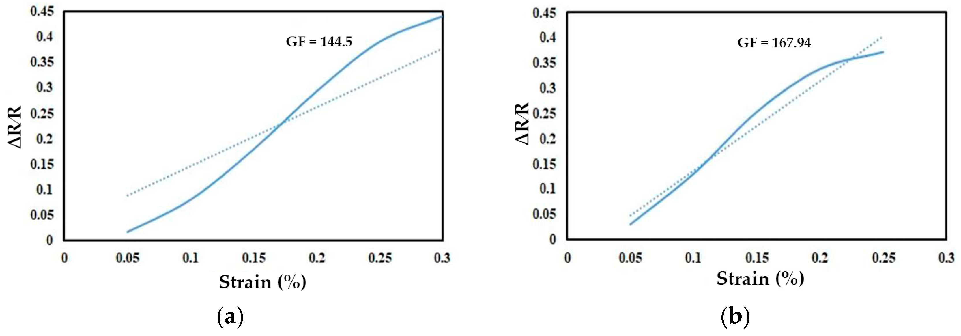
The variation in gauge factors between samples A (CNT/PANI) and B (CNT/PANI/silicone rubber) highlights the influence of the tunneling effect on electrical resistance (
Figure 8a,b). As the distance between neighboring CNTs changes under tensile stress, the tunneling resistance within the polymer matrix shifts, ultimately affecting the overall electrical resistance of the thin film layer [
39,
40]. This understanding helps explain the higher gauge factor in sample B, where the presence of silicone rubber amplifies this tunneling effect.
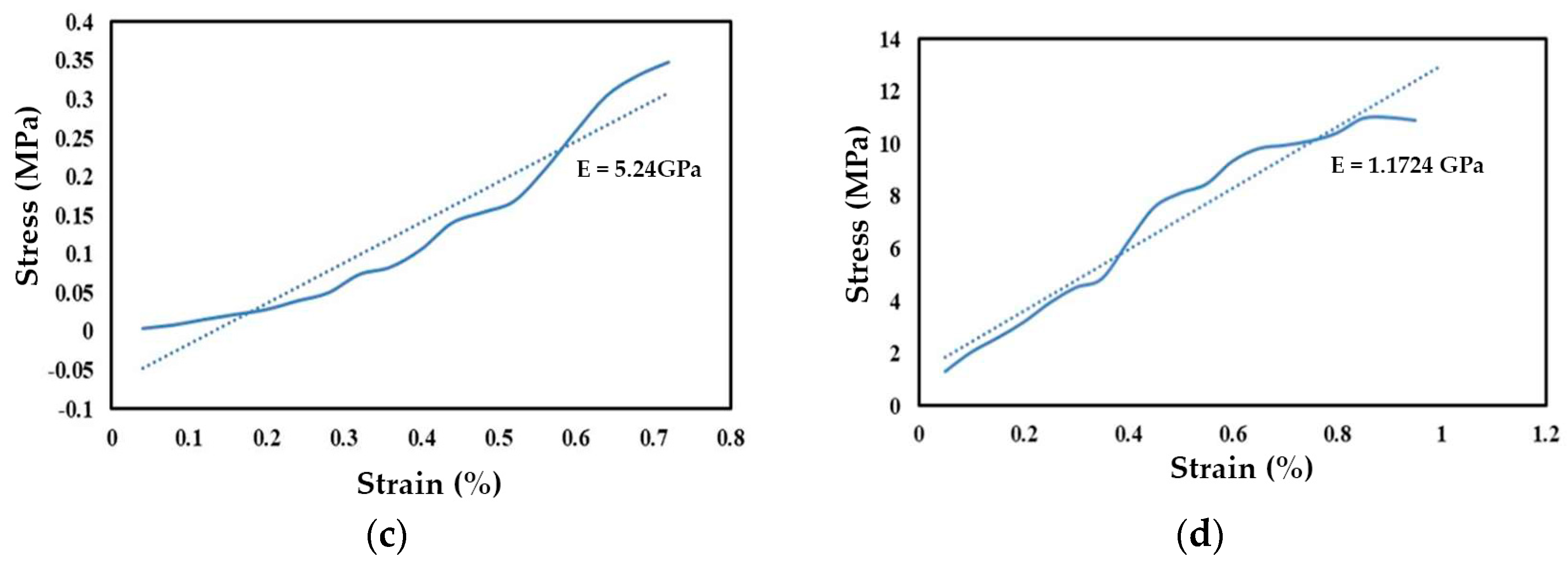
The Young’s modulus values shown in
Figure 8c,d, reflected in the stress–strain curves of samples A (CNT/PANI) and B (CNT/PANI/silicone rubber), demonstrate the contribution of silicone rubber. The decrease in Young’s modulus for the silicone-rubber-containing sample is attributed to the inherently lower Young’s modulus of silicone rubber [
41]. In general, the presence of elastomer in this structure causes a portion of the applied force to be absorbed by the elastomer’s reorientation, reducing the modulus of elasticity. Thus, the decrease in Young’s modulus in the CNT/PANI/silicone rubber structure enhances piezoresistive behaviors and increases its resilience, making it a suitable option for stretchable wearable sensors [
42].
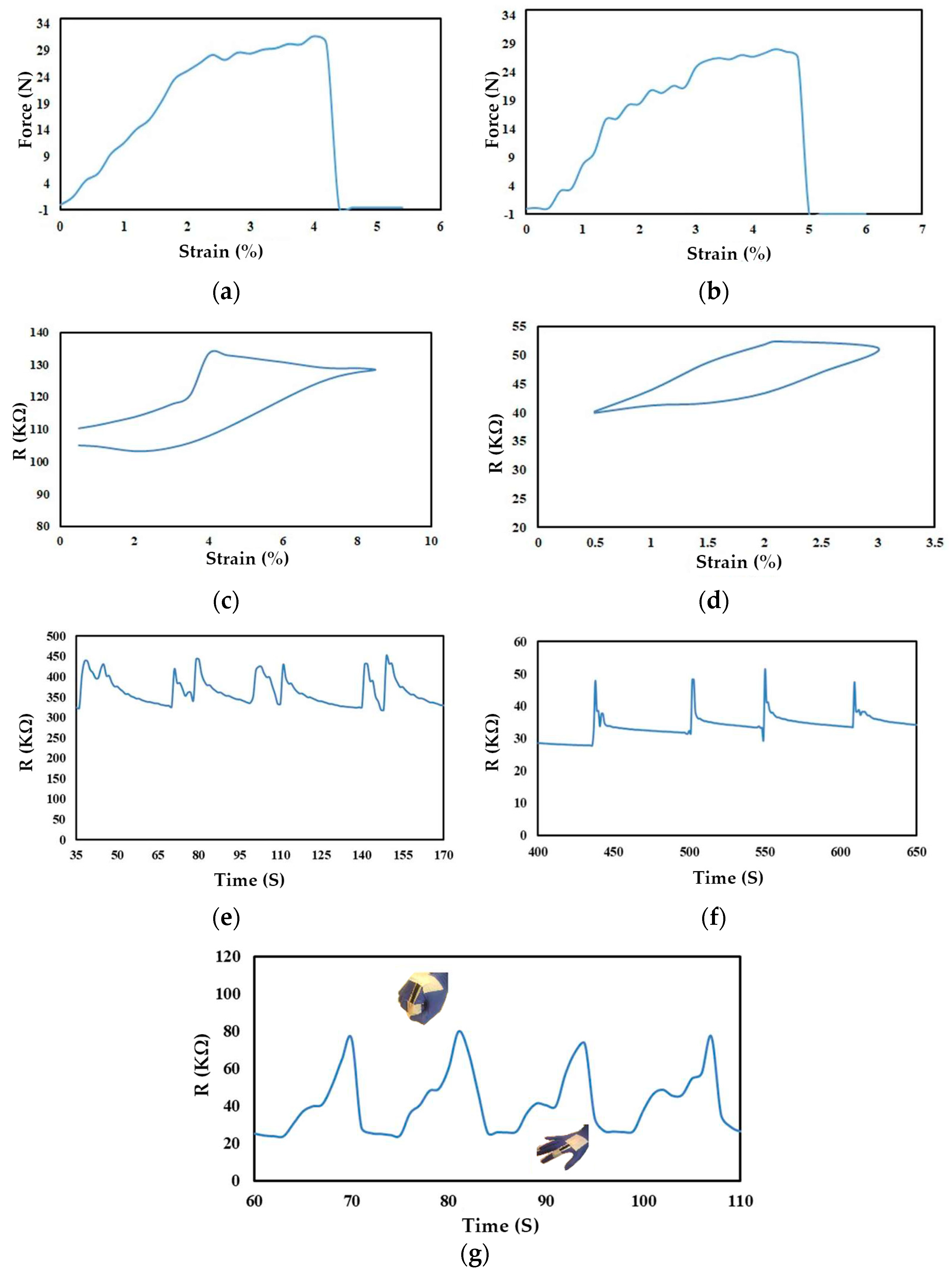
The tensile strength obtained for samples A (CNT/PANI) and B (CNT/PANI/silicone rubber) (
Figure 9a,b) is approximately within the same range because both samples were tested on a low-stretch fabric. Additionally, the percentage of silicone rubber used in sample B is low and does not penetrate the fabric structure.
The obtained results for samples A and B indicate the presence of hysteresis in both structures (
Figure 9c,d), but due to the presence of silicone rubber in structure B, the initial and final points of the curve align, and no residual stress remains in structure B. Overall, the presence of silicone rubber in the CNT/PANI/silicone rubber structure enables the structure to be reversible and maintains the connections between the matrix, resulting in the sample returning to its initial state, i.e., the unloaded state [
43].
The conductivity level of the CNT/PANI and CNT/PANI/silicone rubber samples decreases under applied load and increases when the load is removed.
The response and recovery times of samples A and B showcase the impact of silicone rubber penetration into the porous polymer structure. This elastic conductive network accelerates the strain sensor’s return to its initial state, emphasizing the importance of material architecture in achieving rapid response times [
44,
45].
The dynamic stability illustrated by the resistance change graphs during cyclic loading and unloading cycles differentiates the advantages of silicone rubber. Sample B exhibits superior stability due to the presence of silicone rubber, showing its role in maintaining stable electrical connections [
46].
In sample A, the superplastic behavior occurs gradually in two stages, which could be due to the capacitive behavior developed in the sample [
47,
48]. In sample B, the resistance level suddenly increases at the moment of load removal, indicating superplastic behavior (
Figure 9e,f). This behavior is dependent on the viscoelastic property created in the polymeric structure of carbon/silicon rubber nanotubes, which is observed at high loading rates [
49].
The final practical demonstration using the strain sensor attached to a human hand further reinforces the real-world applicability of the developed technology (
Figure 9g). The correlation between hand movement and resistance changes demonstrates the potential for this strain sensor to capture and respond to dynamic strain variations.
5. Conclusions
In conclusion, this study delved into the comprehensive analysis of CNT/PANI nanocomposites and their suitability as strain sensors. The fabrication process involved simulation using LAMMPS software, nanocomposite synthesis, and the extraction of sensor performance parameters. Two samples, sample A (CNT/PANI) and sample B (CNT/PANI/silicone rubber), were analyzed. Electron microscopy imaging verified the successful functionalization of CNTs and the effective deposition of PANI, resulting in a porous coating that optimizes the properties of the CNTs. By incorporating silicone rubber into the composite structure (sample B), we achieved an enhanced gauge factor of 167.94 compared to 144.5 for sample A. The improved performance of the CNT/PANI/silicone rubber strain sensor can be attributed to the tunneling phenomenon, where electrons can tunnel through the polymer matrix as the distance between adjacent CNTs decreases. Mechanical analysis through stress–strain curves clarified the impact of silicone rubber. Sample B, which contains silicone rubber, depicted a lower Young’s modulus compared to sample A due to the lower Young’s modulus of silicone rubber. Indeed, the elastomer in the structure allows for a redistribution of applied force, reducing the modulus of elasticity. This decrease enables piezoresistive behavior and increased resilience, making the sensor suitable for wearable applications. Hysteresis was observed in both samples, but the presence of silicone rubber in Sample B improved the alignment of the graph’s starting and ending points. Sample B also demonstrated reversibility, maintaining the connections between the matrices and restoring the sample’s resistance to its initial state. The conductivity behavior, response, and recovery times shown in the strain sensors highlighted the multifaceted influence of material architecture and composition. The strain sensor’s successful response to human hand movement demonstrates its real-world utility, highlighting its capability to capture dynamic strain changes in real time. Overall, the fabricated CNT/PANI/silicone rubber strain sensor exhibited superior performance compared to the CNT/PANI counterpart. These sensitive and reversible strain sensors hold great promise for human motion detection, with potential applications in wearable technology and human–machine interfaces.


