Abstract
The use of Light Amplification by Stimulated Emission of Radiation (i.e., LASERs or lasers) by the U.S. Department of Defense is not new and includes laser weapons guidance, laser-aided measurements, and even lasers as weapons (e.g., Airborne Laser). Lasers in the support of telecommunications is also not new. The use of laser light in fiber optics has shattered thoughts on communications bandwidth and throughput. Even the use of lasers in space is no longer new. Lasers are being used for satellite-to-satellite crosslinking. Laser communication can transmit orders-of-magnitude more data using orders-of-magnitude less power and can do so with minimal risk of exposure to the sending and receiving terminals. What is new is using lasers as the uplink and downlink between the terrestrial segment and the space segment of satellite systems. More so, the use of lasers to transmit and receive data between moving terrestrial segments (e.g., ships at sea, airplanes in flight) and geosynchronous satellites is burgeoning. This manuscript examines the technological maturation of employing lasers as the signal carrier for satellite communications linking terrestrial and space systems. The purpose of the manuscript is to develop key performance parameters (KPPs) to inform the U.S. Department of Defense initial capabilities documents (ICDs) for near-future satellite acquisition and development. By appreciating the history and technological challenges of employing lasers, rather than traditional radio frequency sources for satellite uplink and downlink signal carriers, this manuscript recommends ways for the U.S. Department of Defense to employ lasers to transmit and receive high bandwidth, and large-throughput data from moving platforms that need to retain low probabilities of detection, intercept, and exploit (e.g., carrier battle group transiting to a hostile area of operations, unmanned aerial vehicle collecting over adversary areas). The manuscript also intends to identify commercial sector early-adopter fields and those fields likely to adapt to laser employment for transmission and receipt.
1. Introduction
The demand for data—raw facts—and its successful evolution to information—arranged in context—is growing, arguably at an exponential rate. This is true for the civil, commercial, and security sectors (i.e., defense; specifically, the U.S. Department of Defense). Civil space activities include those to explore space and advance human understanding; commercial activities are those where private companies and industries provide services with the intent of making a profit [1]. During 1991’s Operation DESERT STORM in Iraq, the U.S. Department of Defense had access to ninety-nine mega-bits per second of bandwidth. In 2003, access for Operations ENDURING FREEDOM in Afghanistan and IRAQI FREEDOM had grown to thirty-two-hundred mega-bits per second. In 2007, U.S. Department of Defense planners projected the need for sixteen giga-bits per second by 2010 [2]. A rudimentary analysis concludes that the U.S. Department of Defense requires an order of magnitude increase in bps every nine years. The U.S. Department of Defense’s demand for data, information, and intelligence is exceeding its satellite communications capacity, whether owner-operator or contracted. Transitioning to laser-based satellite communications, in part due to its orders of magnitude greater throughput, is becoming necessary for the U.S. Department of Defense. Laser communications could provide from ten to one-hundred times better data rates than radio, due to the higher bandwidth [3].
This manuscript examines the technological maturation of employing lasers as the signal carrier for satellite communications linking terrestrial and space systems. The purpose of the manuscript is to inform the U.S. Department of Defense initial capabilities documents (ICDs) or key performance parameters (KPPs) for near-future satellite acquisition and development. By appreciating the history and technological challenges of employing lasers, rather than traditional radio frequency sources for satellite uplink and downlink signal carriers, this manuscript recommends ways for the U.S. Department of Defense to employ lasers to transmit and receive high bandwidth and large-throughput data from moving platforms that need to retain low probabilities of detection, intercept, and exploit (e.g., carrier battle group transiting to a hostile area of operations, unmanned aerial vehicle collecting over adversary areas). The manuscript also intends to identify commercial sector early-adopter fields and those fields likely to adapt to laser employment for transmission and receipt.
2. Materials and Methods
This section begins with a quote succinctly introducing the history of laser employment, followed by chronological articulation before and through the twenty-first century. Following brief chronology, brief paragraphs introduce historical applications, finalizing the preparation for discussion of the results.
2.1. History of Laser Employment as Link Source
Relevant laser applications have a long, interesting pedigree that harks back to the beginning of the space era.
“The registered history of laser technologies for space application starts with the first laser echoes reflected off the Moon in 1962. Since then, photonic technologies have become very prominent in most technical development. Their presence has also dramatically increased in space applications thanks to the many advantages they present over traditional equivalent devices, such as the immunity against electromagnetic interference, as well as their efficiency and low power consumption. Lasers are one of the key components in most of those applications.”[4,5]
The application of lasers for communications across great distances has an even longer pedigree, although the notions were not actualized until the last century.
2.1.1. Prior to the Twenty-First Century
Shortly after WWII, Arthur C. Clarke wrote about employing light beams to transmit information [6]. His foresight was not realized until the 1960s with the development of the laser. Furthermore, it was not demonstrated as intended until the 1995 bidirectional ground-to-orbit laser communication demonstrations. The program successfully used lasers to uplink and downlink to the engineering test satellite-VI in elliptical geosynchronous transfer orbit, sending and receiving at a 1 mega-bits per second rate [7]. This unhurried pace (50 years between idea and demonstration: 30 years between technology development and adaptation) exemplifies the field of laser communications.
Before considering lasers for uplinks and downlinks [8], lasers were employed for geodesy first [9,10,11,12,13,14,15,16,17,18,19,20,21,22] and also orbital determination [23,24,25,26,27,28,29,30,31,32,33]. The 1990s jump-started scientific examination of space and satellite laser communications [34,35,36,37,38,39,40,41,42,43,44,45,46,47,48,49,50,51,52,53]. Over roughly the next decade, the U.S. national air and space administration, and the European and Japanese space agencies, completed successful trials of space-based laser communications [34]. In 2001, the European space agency’s semiconductor intersatellite link experiment and advanced relay and technology mission satellite received fifty mega-bits per second from the French observation satellite SPOT-4 [34], demonstrating bi-directional links between a geosynchronous orbiting satellite and both low-earth orbiting satellite and ground receiving stations [35], which is depicted in Figure 1. That same year, the geosynchronous lightweight technology experiment also successfully demonstrated bi-directional laser communications, and this time added an aircraft to the reception station list [35].
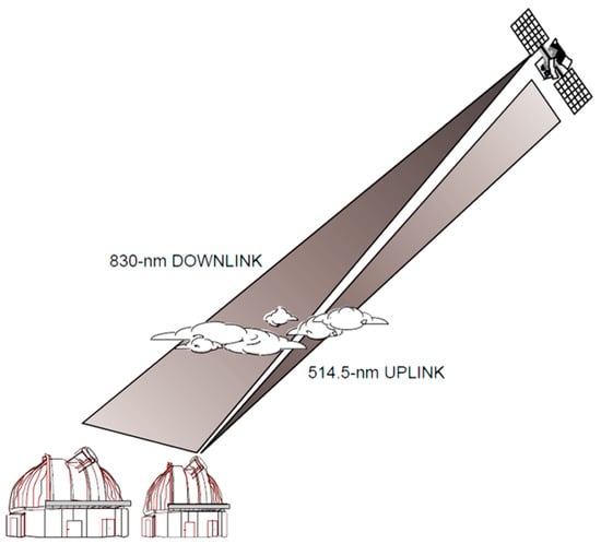
Figure 1.
Satellite uplink and downlink with terrestrial stations from [8]: 0.6 m transmitter uplinking at 514.5 nanometers and 1.2 m receiver downlinking at 830 nanometers.
2.1.2. Early Twenty-First Century
The advanced relay and technology mission satellite laser communications capability was supplied by the optical payload laser experiment and the laser-utilizing communications equipment. Both systems provided source laser beams, at ten milli-watts and forty milli-watts, respectively. However, a lesson learned from the semiconductor intersatellite link experiment was that even with the laser-utilizing communications equipment beam’s quadruple power, it failed to provide sufficient irradiance at ground-to-geosynchronous orbit ranges to perform initial acquisition [37]. However, the semiconductor intersatellite link experiment demonstrated a downlink bit error rate of 10−10 [37].
The semiconductor intersatellite link experiment did, however, reinforce a foundational advantage of laser communications over radio frequency communications: that laser communications requires less size, weight, and power for a given data rate [36]. Demonstrated years later was a 2.5 giga-bits per second communications link with a roughly three decibel link margin across a range of forty-two-thousand kilometers, a capability that can be made using a two-point-two meter antenna for Ka-band (weighing one-hundred fifty-three kilograms), a one-point nine meter antenna for a millimeter band (weighing one-hundred thirty-two kilograms), and a ten centimeter optical system for a 1.55 micrometer wavelength (weighing sixty-five kilograms) [37].
In 2013, the U.S. national air and space administration began examining laser communications in earnest, focused in support of the further exploration of Mars and beyond. That year, the administration launched the lunar laser communications demonstrator [42,43], a high-rate demonstration of space laser communications [42].
“The Lunar Laser Communication Demonstration (LLCD) was conducted on NASA’s Lunar Atmosphere and Dust Environment Explorer (LADEE) satellite that launched in late 2013 [41]. The LLCD payload demonstrated optical communication in the 1.5 μm band utilizing pulse position modulation (PPM) with 16 slots (16-PPM) to downlink data from the moon to a receiver on Earth at 622 Mbps. The uplink from the optical ground terminal on Earth utilized 4-PPM to uplink data at 20 Mbps to LLCD [40]. LADEE [40,41] was a small satellite that weighed 383 kg at launch and the entire spacecraft consumed 295 W of power during its mission”[39]
The lunar laser communications demonstrator demonstrated is shown in Figure 2, a six-hundred-twenty-two mega-bits per second datalink at a range of four-hundred-thousand kilometers; an achievement at ten times the approximate range of a ground-to-geosynchronous orbit link while overcoming a one-hundred fold link loss [43]. Late in 2013, for thirty days the lunar laser communications demonstrator communicated in duplex from a lunar orbiting satellite to both earthbound locations, as well as the lunar atmosphere and dust environment explorer. This feat is illustrated one of the benefits of laser communications and very high data rates, since the achievement was hailed as both the highest data rate and the longest distance laser communications had yet achieved. Lunar laser communications demonstration demonstrated an order of magnitude higher data rate uplink, twenty mega-bits per second (error-free), than the best Ka-band radio system [43].
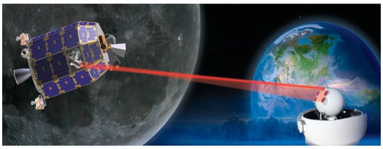
Figure 2.
NASA’s First Space Laser Communication System Demonstration [43].
NASA’s follow-on to lunar laser communications demonstration is the laser communications relay demonstration mission. The laser communications relay demonstration will use laser communications to transmit at rates from ten to one-hundred-times faster than radio frequency communications [46,47,48]. The laser communications relay demonstration will leverage commercial optical fiber telecommunications components and employ a multi-rate modem to generate download rates ranging from two mega-bits per second to 1.244 gigabits per second [43]. If found successful, laser communications relay demonstration technologies will be applied to two upcoming missions by the U.S. national air and space administration: the integrated laser communications relay demonstration low-earth orbit user modem and amplifier terminal, and the optical-to-Orion project [3].
2.1.3. Satellite Laser Range Finding
This section describes satellite range finding in accordance with [8,20,33,54,55,56]. European Space Agency’s Copernicus Program includes the Earth observation satellite constellation called the Sentinel-3, comprised of two spacecraft: Sentinel-3A and Sentinel-3B with two more (subsequently named) yet to be delivered [57]. Instruments dedicated to the precise measurement of sea and land surface temperatures, ocean and land surface color, and surface topography are onboard Sentinel-3A/B. Laser retroreflectors for the satellite laser ranging instrument SLR and the Doppler Orthography and Radio positioning Integrated by Satellite (DORIS) antenna aid global positioning system navigation. Strugarek [9] investigated using these instruments for global geodesy (including measurement of motion of the geo-center) in addition to realization of the terrestrial reference frame. Earth rotation parameters were also investigated using 2016–2018 data. SLR site range bias estimates preceded analyzed solutions using disparate constraining tests of the network and a different number of orbital arcs.
“The repeatability of SLR station coordinates based solely on SLR observations to S3A/B is at the level of 8–16 mm by means of interquartile ranges even without network constraining in 7-day solutions. The combined S3A/B and LAGEOS solutions show a consistency of estimated station coordinates better than 13 mm, geocenter coordinates with a RMS of 6 mm, pole coordinates with a RMS of 0.19 mas and Length-of-day with a RMS of 0.07 ms/day when referred to the IERS-14-C04 series.”[9]
To aid fiducial reference systems, the rotation of the earth, and basic physics, such as modeling the gravity field, planning for geodetic satellites with retro-reflectors and high mass-to-area ratios was underway by the early 1970s.
“Early geode-tic satellites were Starlette, launched in 1975 by Cen-tre National d’Etudes Spatiales (CNES), and LAGEOSin 1976 by the National Aeronautics and Space Ad-ministration (NASA). Recent geodetic satellites include LARES, launched in 2012, and LARES-2 under development, both by the Italian space agency (ASI). Today a complex of these ‘geodetic satellites’ from low to high altitude Earth orbits supports many space geodesy requirements. This manuscript will discuss the evolution of the geodetic satellites from the early days, through current programs and out to future needs as we approach our goal for millimeter accuracy.”[9]
2.1.4. Demonstrations on Fast-Moving Platforms
Not to belittle the work done in orbit, but very little of the above experimentation examined the impacts of terminals moving at greater speeds (low-earth orbit at seven kilometers per second versus geosynchronous orbit at three kilometers per second) or being affected by in-atmosphere turbulence; this is changing. The German aerospace center (Deutsches Zentrum fur Luft- und Raumfahrt, i.e., DLR) are conducting experiments using their optical space infrared downlink system, a small laser communications terminal orbiting in low-earth orbit, demonstrating the requirements for high-precision alignment between stations [49,50]. Additionally, in 2013, DLR went on to successfully demonstrate laser communications from a jet aircraft. Flying at roughly sixty-five percent the speed of sound (eight-hundred kilometers per hour), the test demonstrated a transmission rate of 1.25 giga-bits per second at sixty kilometers. The test not only demonstrated the ability to overcome atmospheric turbulence-driven distortions, but also the impact of fast flight maneuvers and strong vibrations [49].
3. Results
Strategic nuclear forces have unique communications requirements, which include capability to work through challenging atmospheric environments, and resilience to manmade and natural threats [58].
3.1. Comparisons of Radio Frequency and Optical Systems
This paragraph describes comparisons of radio frequency and optimal systems [54]. Efforts to compare RF and optical systems are primarily focused on answering the question, “Under what conditions should it be desirable to transition from RF to optical communications for high-capacity communications?” The results of [54], depicted in Figure 3, show that each system provides advantages in particular regimes, and the design choice should be viewed with mission specificity in determining a course to follow. Optical systems have the advantage of extremely broad, unregulated bandwidth compared to radio frequency systems. At Ka-band frequencies of thirty-two or thirty-seven to thirty-eight gigahertz, bandwidth is typically five-hundred megahertz. For optical systems at 1.5 micrometers, the bandwidth may be one-thousand-times larger, allowing optical systems to carry substantially more information. For radio frequency systems to compete in a bandwidth-constrained environment, they must resort to bandwidth-efficient modulation for data rates above one gigabit per second, which is neither power-efficient nor mass-efficient for the transmitting terminal. Optical systems typically would have smaller received apertures and lower power efficient transmitters and receivers. A comparison of the burden to a spacecraft by both optical and radio frequency communications systems for data rates of ten, one-hundred, and one-thousand mega-bits per second and large distances is taken from [54]. For the comparisons drawn, the optical and RF ground terminals were selected to be similar in cost. The radio frequency system selected was composed of forty-five twelve-meter antennas, whereas the selected optical system was equivalent to a ten-meter optical telescope. Potential differences in availability were disregarded since the focus of the study was on spacecraft mass and power burden for high-rate mission data, under the assumption that essential communications will be provided by low-rate, high availability radio frequency. For both the radio frequency and optical systems, the required equivalent isotropic radiated power, for a given data rate and a given distance, was achieved by a design that realized the lowest possible communications subsystem mass (aperture plus power) consistent with achieving the lowest technology risk. A key conclusion of that study is that optical communications has great potential for high data rates and distances of 2.67 astronomical units and beyond, but requires research and development, and flight demonstrations to prove our technologies.

Figure 3.
Technology Complexity Levels (see Table 1) for radio frequency and optical communication systems for various curves of constant equivalent isotropic radiated power, (a) RF communications systems, (b) Optical communication systems.

Table 1.
Technical Risk in Terms of Complexity.
3.2. Technical Challenges of Employing Lasers versus Radio Frequency Communications
The transition from “traditional” radio frequency waves to near- and in-band visible light waves invokes the inverse relation of frequency and wavelength—as frequency increases, wavelength decreases. The significant advantage of employing laser communications comes from increased bandwidth, and that comes from increased frequency (and with laser communications the ability to employ the entire bandwidth). Laser crosslinks will jump from millimeter wave-generated high giga-hertz bandwidths to infrared and visible light-generated tera-hertz bandwidths, enabling data rates from optical carriers to be from two-hundred to two-thousand times greater than ’‘traditional” radio frequency [51].
However, as the history above shows, the benefits are yet to be realized as the maturation of the technology remains sluggish. The use of a low divergence beams, a traditional benefit of lasers, complicates linking two moving targets. Additionally, radio waves are less affected by atmospheric interference, something necessary for our most sensitive and critical missions. Additionally, while the increased frequency is desired for increased bandwidth, it comes with a cost of increased free space path loss as a function of the base-ten logarithm log10(f).
As depicted in Figure 4, taken from [55], radio frequency transmission through the atmosphere is well-known and concentrates on “windows” of transmission, especially for long ranges. This section of the manuscript consolidates the concerns for transmission of laser communications signals.
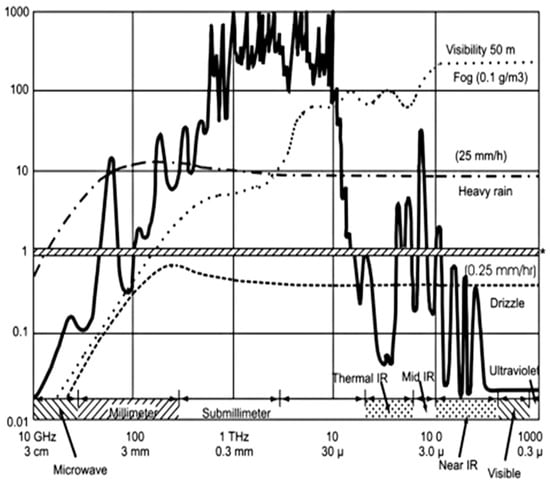
Figure 4.
Radio frequency atmospheric attenuation in decibels per kilometer (on the ordinate) versus frequency and wavelength (on the abscissa).
3.2.1. Beam Divergence, Vibration, and Jitter
The frequency advantage of lasers comes from their incredibly small wavelengths. By comparison, optical (i.e., laser) wavelengths are ten-thousand-times shorter than microwaves, allowing data to be transmitted in narrow or tight beams [52]. The narrowness of those beams (beam width) is equivalent to their wavelength, divided by the diameter of the optical aperture of the transmitting telescope, scaled by a multiplicative factor from 2.24–2.28 [51,59].
Referencing Figure 5, narrow beams spread less during travel through space and require less power for transmission [46,53]. Dunbar [46] provides the following quote:
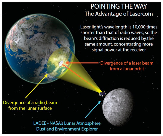
Figure 5.
Divergence Examples—Radio and Laser [43].
“For example, a typical Ka-Band signal from Mars spreads out so much that the diameter of the energy when it reaches Earth is larger than Earth’s diameter. A typical optical signal, however, will only spread over the equivalent of a small portion of the United States; thus, there is less energy wasted.”
Beam divergences are proportional to the wavelength and inversely proportional to the aperture diameter, thus beam spread is more favorable for optical laser transmission. The smaller wavelength permits smaller antennae, whose gain scales are inversely proportional to the square of the wavelength. Reference Equation (1) for a comparison by ratio of antenna gain.
Unfortunately, the transmitting platform’s physical vibration can produce errors (i.e., the rate of bit errors or bit error rate), akin to the light from a flashlight held by a frightened person. That vibration may source certain pieces of equipment within the satellite (e.g., solar arrays, reaction wheels, control movement gyros.) The vibration can also manifest as a “jerkiness” of the transmitting platform as it moves along in orbit [53]. Satellites in orbit experience the four-hundred to one-thousand hertz of vibration and shaking [51].
Jitter is a special category of vibration, particular to optics. Jitter is a high-frequency, typically sinusoidal, undesired fluctuation that causes a reduction in beam intensity at the target (irradiance). Watkins et al. [60] demonstrate, with the example of a softball-sized beam, that one milliradian of jitter will have a one-hundred fold decrease in irradiance at a target positioned five-hundred kilometers away.
3.2.2. Acquisition, Tracking, and Pointing
While a narrow beam is advantageous for thwarting detection, interception, and exploitation (discussed later), and for lowering transmitting powers, it does necessitate higher precision in aligning sending and receiving stations. With a small beam divergence (relative to a traditional radio frequency signal), laser communications must address “leading” the receiver by a point-ahead angle. This angle is required due to the finite speed of light and the relative motion of the satellite. This is not a negligible value and may amount to tens of microradians [37]. Just as beam width is dependent on wavelength and the diameter of the optical aperture of the transmitting telescope, so too is pointing accuracy, where accuracy is cited in [37] as the wavelength divided by twenty times the aperture diameter.
In some cases, the pointing accuracy of a centimeter-class antenna must be within an accuracy of one micro-radian [37]. Laser beam pointing error is indicated by a special vibration term, while the receiving optical platform error maintaining pointing towards the transmitter are dealt with in the signal’s budget for power [59].
Bifocal Relay Mirror Spacecraft
Substantial developments in acquisitions, tracking, and fine pointing evolved in the twenty-first century and continue to this day [60,61,62,63,64,65,66,67,68,69,70,71,72,73,74,75,76,77,78,79,80,81,82,83,84,85,86,87,88,89,90,91], including substantial development in target acquisition [61,64,65,67,68,69,70,71,72], target tracking [62,63,75,76,78,81,83,84,85,86,87,89,90,91], and fine pointing [60,73,74,77,79,80,82,88] at the Naval Postgraduate School, among several other institutions achieving microradian pointing accuracy and closely pursuing nano-radian accuracy.
3.2.3. Atmospheric Impacts
For all the above challenges, the efforts expended to achieve a closed laser communications link may be for nothing if atmospheric impacts are not accounted for. Assuming an atmosphere-penetrating wavelength is selected, the transmitted signal must overcome two detractors: scattering (i.e., fades) and absorption. As a laser communications beam’s wave front transits the atmosphere, it encounters air with non-uniform density. This differing uniformity changes the air’s index of refraction. These changes induce error into the transmitted signal, which registers as an increased bit error rate and is referred to as fade [61].
A laser beam produces self-induced change to the index of refraction when they heat the air through which it propagates. This index change results in the beam spreading or “blooming”, losing focus and reducing the transmitted power. Remedies to blooming include reducing the transmitted power, selecting an atmosphere-appropriate wavelength, or using means to spread the beam’s power (e.g., slewing or increasing the optical aperture of the transmitting telescope) [92].
While clear air causes fade, occluded air causes the beam to scatter. Scattering is generated by molecular and aerosol absorption, as well as large particulates in the air, including precipitation, such as rain, fog, clouds, and snow. The application of Beer’s Law is recommended in determining the loss due to this scattering and absorption [59].
Many of the atmosphere-induced link closing difficulties can be addressed through the application of test pulses and adaptive optics [92]. The creation and transmission of a distorted wave front that uses the atmosphere-like glasses to “correct” the beam at the receiver is beyond the scope of this manuscript but is a key requirement for address in initial capabilities documents (ICDs) and via key performance parameters (KPPs).
With this basic discussion of technical challenges and recent progress addressing the challenges, the final section of this manuscript summarizes advantages and disadvantages and additionally makes specific recommendations for key performance parameters for initial capability documents for near-future satellite acquisition and development.
Transmittance through the atmosphere is described by Equation (2), where is zenith angle and is the atmospheric attenuation coefficient. The integrand h is the vertical height of the atmosphere up to a specified H from nominal [55]. The phase coherence radius is expressed using variable .
Atmospheric turbulence further complicates things in three ways: (1) wander of a beam with initial size of a beam of W0, as described in Equation (4), (2) beam spreading, and (3) beam scintillation, as described in Equation (5) for phase various coherence radii , which may be calculated using [93].
Attenuation in Fog
Fog introduces problems of both scattering and absorption [58]. Equation (4) illustrates the empirical model for Mie scattering [93]. The scattering coefficient is taken from [94] and displayed in Table 2, and whose result may be seen in the novel plot in Figure 6.
Table 2.
Scattering coefficient.
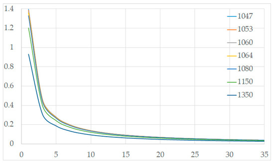
Figure 6.
Attenuation for various laser wavelengths ranging from 1047 to 1350 nanometers with visibility range (km) on the abscissa and fog attenuation on the ordinant.
Note in Figure 4 the nominally similar attenuation regardless of laser wavelength.
Attenuation in Rain
Since the size of rain drops relative to optical wavelengths is relatively larger than the instance of fog, the attenuation in rain is less pronounced, ranging from one to ten decibels per kilometer [95].
4. Discussion
The U.S. Department of Defense has concerns employing laser up and down links. Defense necessities must be balanced against the economic feasibility of system procurement. Every procurement program is judged on its merits, and that usually begins with an advantages–disadvantages list. This section of the manuscript describes simply that. From the U.S. Department of Defense’s perspective, what are the advantages and disadvantages of employing laser communications uplinks and downlinks.
4.1. Advantages—Throughput, Power, Information Protection
Warfighters like that crosslinks provide from ten to one-hundred times higher data rates than traditional radio frequency [3]; that laser crosslinks can be protocol independent and able to support multiple platforms and interfaces [35]; that laser crosslinks have a low probability of detection, of interception, and of exploitation [36].
The programming and budget personnel like that: laser crosslinks exists in an radio frequency band that is currently license-free; that laser crosslinks components tend to have smaller mass, power, and volume requirements [96]; that laser crosslinks have a low probability of detection, of interception, and of exploitation. Programmers also like that laser crosslinks systems are easier to install (less funding for labor) and have lower cost per bit ratios (i.e., lower signal operating costs) [35].
The primary advantage of using the small wavelengths of laser crosslinks is that the orders of magnitude-increased throughput-laser crosslinks provide higher bit rates with lower bit error rate. Where a microwave link at geosynchronous orbit ranges can support data rates in the tens of mega-bits per second, at the same ranges, laser crosslinks can support in the tens of giga-bits per second [52]. Laser crosslinks have the potential to support in the terabits per second range—which is akin to streaming two-hundred-thousand high-definition movies simultaneously [96]. Laser crosslinks also support employing the entire bandwidth of the signal [46], providing the opportunity for full duplex operations [61].
Auspiciously, the power requirements for laser crosslinks are much lower (than traditional radio frequency) while the efficiency is higher. As a rule-of-thumb, laser crosslinks can send ten times more data using ten times less power [96]. Additionally, the smaller signal power requirement allows for smaller collecting antennae, an advantage seen in a smaller size, weight, and power [52]. During the early days of human spaceflight, the U.S. national air and space administration’s Apollo spacecraft communicated with the Earth using seven-foot antennae. In 2009, the lunar reconnaissance orbiter launched by the U.S. national air and space administration used a two-and-a-half-foot antenna. Meanwhile spacecraft laser terminals can be a mere four inches [42].
Laser crosslinks are advantageous in both ensuring the message gets from sender to receiver, and to assuring that the receiver is confident the message is true and undisturbed. In addressing warfighting information protection, the extremely small beam divergence both minimizes signal loss and increases security by making jamming problematic [7]. The narrow beam makes both in-path interception difficult as well as interference both to and from adjacent satellites [7]. Additionally, using well-selected optical signals makes for immunity from electromagnetic interference, while quantum key distribution adds additional security.
“Quantum key distribution (QKD) uses individual light quanta in quantum superposition states to guarantee unconditional communication security between distant parties. However, the distance over which QKD is achievable has been limited to a few hundred kilometers, owing to the channel loss that occurs when using optical fibres or terrestrial free space that exponentially reduces the photon transmission rate. Satellite-based QKD has the potential to help to establish a global-scale quantum network, owing to the negligible photon loss and decoherence experienced in empty space. Here we report the development and launch of a low-Earth-orbit satellite for implementing decoy-state QKD-a form of QKD that uses weak coherent pulses at high channel loss and is secure because photon-number-splitting eavesdropping can be detected. We achieve a kilohertz key rate from the satellite to the ground over a distance of up to 1200 kilometres. This key rate is around 20 orders of magnitudes greater than that expected using an optical fibre of the same length. The establishment of a reliable and efficient space-to-ground link for quantum-state transmission paves the way to global-scale quantum networks.”[53,97]
4.2. Disadvantages—Acquisition, Tracking, and Pointing; the Atmosphere
If not appreciated from above, acquisition, tracking, and pointing between a fixed ground station and a “slow moving” geosynchronous orbiting satellite is difficult on the best of days. The challenge of introducing two moving objects (e.g., transmitting from an unmanned aerial vehicle in flight to a geosynchronous orbiting satellite) is akin to “... trying to hit a bullet with a smaller bullet whilst wearing a blindfold, riding a horse” [98].
Acquisition, tracking, and pointing requirements expand to include the need for highly accurate ephemeris data, the point-ahead angle, pointing within an error budget, and choosing to not employ a guidance beacon (pointing aid) to maintain low probabilities of detection. While the above requirement for an acquisition, tracking, and pointing accuracy of one microradian was done as both sample mathematical calculation and as hyperbole, potential beam widths of twenty microradians may require pointing accuracies of ten microradian or less [7,34,37].
There is one reprieve to acquisition, tracking, and pointing attributed to laser crosslinks using optical links. As most satellites employ solar panels to generate electrical power, those same panels (the photovoltaic panel or other photo-detector components) can serve as a target for an uplink signal. The large surface area panels greatly simplify the requisite precision needed for uplink acquisition, tracking, and pointing [99].
If the difficulties in mastering the acquisition, tracking, and pointing of two moving targets fails to warrant pause, then the effects of transmitting optical links through the atmosphere must. Near and in-band visible light waves are notoriously fickle for having energy absorbed by the atmosphere. Additionally, atmospheric non-uniformity leads to beam bending and scattering; if strong enough, beam break-up due to loss of coherence.
However, as evidenced by very recent progress [100,101,102,103,104,105,106,107,108,109,110,111,112,113,114,115,116,117,118,119,120,121,122,123,124,125,126,127,128,129,130,131], determined engineers, partnered with a tenacious defense funding programmer, will overcome the disadvantages to reap the advantages and make U.S. Department of Defense laser crosslinks a reality.
4.3. Modifying Satellite ICDS and KPPs for Laser Communications
The primary advantage of U.S. Department of Defense adoption of emerging technology is that the cost is rarely a limiting factor. Pursuing exquisite solutions with lengthy development periods is not anathema to the Department. That belief leads to two possible recommendations for the U.S. Department of Defense adoption of laser crosslinks. First, continue “steady as she goes” development, driving the requirements for a one-off jack-of-all/master-of-all solution. Second, pursue a “sufficient” solution supported by in orbit hardware that is resilient in its longevity, and a combination of terrestrial hardware and system-wide software that bears the brunt of the updates and enhancements Executing—on recommendation—two, allows for mass production of “black box” systems (built with modifiable off-the-shelf or “MOTS” hardware) that can be payload hosted on government, civil, and commercial satellites, assembling a webbed network of both bent-pipe and processing nodes providing true world-wide coverage that can be updated not with a screwdriver but with a keystroke. Playing devil’s advocate, selecting the first recommendation would require developing solutions that address arc-second accuracy, nano-radian jitter, and structures that could meet the stringent pointing requirements [60].
4.3.1. Key Performance Parameter (KPP) #1: Adaptive Optics
Regardless of the recommendation selected, the first key performance parameter to address regards optics. Due to unpredictable and changing atmospheric conditions, there is a need for adaptive optics somewhere in the system. The optics are better positioned on the terrestrial end of the system to remove vibration- and jitter-induced bit error rate (which will have to be examined for air and ship platforms) along with addressing adaptive transmit power and beam broadening [37]. The optics must also compensate for various sources of optical noise, including shine from the sun, moon, stars, and other high-irradiance objects [60].
4.3.2. Key Performance Parameter (KPP) #2: Acquisition, Tracking, and Pointing
The second key performance parameter links to the first by addressing acquisition, tracking, and pointing. With the enormous speeds and complex geometries of two moving bodies (transmitter, receiver), point-ahead, zeroing, and tracking “become a formidable challenge” [51]. The short-range, wide-field-of-view, extremely agile, electronically steered, photonic emitter program of the U.S. defense advanced research project agency (DARPA)’s seeks to increase the speed of development and the cost efficiency. This program places optical scanning technology on a microchip (likely taking advantage of agile beam steering, based on microelectromechanical systems [51]), and can sweep a laser more than one-hundred-thousand times per second [132].
4.3.3. Key Performance Parameter (KPP) #3: The Laser Source Parameters
The third key performance parameter sequences with the first and second by adding the laser source. The first decision will be determining the desired wavelength, assuming a selectable/tunable system is not easily developed. Laser “color” must account for ease of amplification (e.g., 1.55-micrometer distributed-feedback semiconductor laser can be boosted by thirty decibels [51]),desired operating areas beyond in-atmosphere (e.g., certain blue-green wavelengths can penetrate sea water and facilitate undersea communications [36,37]), and type of laser—typically a driver of “color” (wavelength), efficiency, and operating life and reliability.
Additionally, the laser and associated modulators must support the desired—both current and future—waveforms for encoding data onto the carrier wave. With the right waveform, high-order modulation and spatial multiplexing techniques may achieve transmission rates reaching one-hundred giga-bits per second [133]. Furthermore, the desire to support multi-beam communications and directional beamforming will require select characteristics regarding “color” coherence.
4.3.4. Key Performance Parameter (KPP) #1: The Transmitter and Telescope
The fourth and final KPP addresses the transmitter and telescope. The impact of atmospheric interruptions cannot be ignored; because the U.S. Department of Defense is interested in mission assurance (and not typically financial constrained), why not require a dual-band transmit and receive system—combined radio frequency/laser bands that use the same telescopic antenna [59]? A combined radio frequency (in the ultra-high frequency band or higher, likely microwave) and laser antenna could simultaneously accommodate both bands “thereby enabling, as a function of the operational environment, a shift from the higher band to the lower band and vice versa” [59]. This would merit evaluation for ship and aircraft operations in foul weather, and to possibly serve as an aide in resolving the acquisition, tracking, and pointing challenge—the radio frequency signal could serve as a beacon to help zero the optical transmission [134].
4.4. Civil and Commercial Sector Adoption
As footnoted above, the motivations for the civil and commercial sectors differ—one for science, the other for finance. Additionally, while their ends may be different, their means and ways are often similar.
The civil and commercial sectors’ motivation for adopting laser communications falls mainly to balancing throughput versus cost. Radio frequency links are costly, due to size (ground stations and transmitter power), access and licensing (congested spectrum), and the control of intellectual property. Laser crosslink systems have demonstrated more efficient and size-, weight-, and power-shrewd operations, including scalable technologies (e.g., CubeSat has the capability to maintain one-hundred mega-bits per second transmissions from fifteen-hundred kilometers from low-earth orbit to ground, and is in development to scale to giga-bits per second rates [135,136]), with development backing from a wide range of sources—academia (e.g., Massachusetts institute of technology), civil space agencies (e.g., European and Japanese space agencies), and even internet titans (e.g., Google, Facebook) [136]. The work of each leads to the production of smaller, more effective, and less expensive data transmission systems, employing cutting-edge laser communications.
Lower costs will come from smaller systems hosted on numerous vehicles including small satellites, or even as independent nanosatellites. TESAT has completed miniaturization actions to supply a host with a three kilogram, one-hundred mega-bits per second to ten giga-bits per second, laser communications system [137]. More immediate, the U.S. national air and space administration laser communications experiment uses a semiconductor laser downlink weighing under twenty-two kilograms and consuming only 81 watts of power [96]. To shrink the laser source and transmitter further will require the further development of short pulse laser light—something like an attosecond in length—and then be able to generate that pulse in something easily manufactured, like a fiber optic cable [53]. One attosecond is a billionth of a billionth of a second.
“Optical communication is becoming more prevalent in orbit due to the need for increased data throughput. Nanosatellites, which are satellites that typically weigh less than 10 kg, are also becoming more common due to lower launch costs that enable the rapid testing of technology in a space environment. Nanosatellites are cheaper to launch than their larger counterparts and may be a viable option for communicating beyond Earth’s orbit, but have strict Size, Weight, and Power requirements. The Miniature Optical Communication Transceiver (MOCT) is a compact optical transceiver designed to provide modest data rates to size, weight, and power constrained platforms, like nanosatellites. This manuscript will cover the optical amplifier characterization and simulated performance of the MOCT amplifier design that produces 1 kW peak power pulses and closes three optical links which include Low Earth Orbit (LEO) to Earth, LEO to LEO, and Moon to Earth. Additionally, a benchtop version of the amplifier design was constructed and was able to produce amplified pulses with 1.37 W peak power, including a 35.7% transmit optics loss, at a pump power of 500 mW. Finally, the modulator, seed laser, amplifier, receiver, and time-to-digital converter were all used together to measure the Bit Error Ratio (BER), which was 0.00257 for a received optical peak power of 176 nW.”[138]
In conjunction with smaller and lighter, making for abundant opportunities to host in orbit, is ubiquity, making for data transmission and reception capability everywhere. In development by the public–private partnership of the European space agency and Airbus is the space-data highway, an “optical fiber network in the sky” using geosynchronous orbiting satellites linked to ground stations and transmitting at 1.8 giga-bits per second (that is an uncompressed six gigabyte high-definition movie in twenty-eight seconds, not one truncated for streaming). The Airbus and European space agency’s space-data highway has completed in excess of twenty-thousand laser connections in last two or more years, downloading more than a petabyte of data, with a reliability rate exceeding ninety-nine percent [100]. Considering the reliability of the components used, including the source, optical pump, and external modulators and so on, a reliability of 0.9998 over ten years of operation without degradation in space has been achieved [51].
A proposed laser communication between the Moon and Earth system would consist of eight solid lasers, each being one-hundred-twenty-five milliwatts, at eight-hundred-and-ten nanometers with five-hundred to fifteen-hundred microradian divergence. Four of the communication lasers would form one six-hundred mega-bits per second channel, transmitting with right-hand circular polarization, and the other four would form the other channel, transmitting with left-hand circular polarization. The total of 1.2 giga-bits per second would be transmitted [59].
Research and development efforts to bring the proposed idea to fruition will depend strongly on six key factors for optimization of the optical link operating at ten gigabits per second duplex at forty-thousand kilometers distance with a bit error rate of one nano bit error per second [51].
13A five-to-eighteen-meter large dish (and associated facility) radio frequency ground segment system costs more than USD one million. A laser transmitter and steering system cost USD fifteen-thousand (e.g., Massachusetts institute of technology’s nanosatellite optical downlink experiment, a thirty-centimeter astronomy telescope costing USD forty-thousand [136].
The European space agency’s secure and laser communication technology supports the research, development, and evolution of laser communications technologies, and provides flight opportunities for their in-orbit verification [101].
5. Conclusions
Laser crosslinks offer several benefits to current and near-future civil, commercial, and security sectors; the most obvious being highly secure, low error, high throughput data communications. Due to the protracted pace of laser crosslink development, melded with the lengthy lead-times for satcom development, compounded by the prolonged government procurement process, makes the time right for inclusive action now. Laser crosslinks technology is sufficiently mature to place payloads of small size, weight, and power on to-be-launched vehicles and follow in short order with the terrestrial legs—whether fixed, at sea, or in the air. The demand for data—raw facts—and its successful evolution to information—arranged in context—is growing, arguably at an exponential rate. The U.S. Department of Defense’s demand for data, information, and intelligence is exceeding its satellite communications capacity. Transitioning to laser crosslink is becoming necessary. Advantages and disadvantages from Section 4 are summarized in Table 3, while the key performance parameters are summarized in Table 4.
Table 3.
Advantages and disadvantages of laser uplinks and downlinks.
Table 4.
Recommendations.
Author Contributions
Conceptualization, M.D.; methodology, M.D.; formal analysis, M.D.; investigation, M.D.; supervision, M.C.; validation, M.C.; resources, T.S.; data curation, M.D.; writing—original draft preparation, M.D.; writing—review and editing, T.S.; funding acquisition, T.S. Please turn to the CRediT taxonomy for the term explanation. Authorship has been limited to those who have contributed substantially to the work reported. T.S. is not a tenured faculty member of Columbia University; rather he is the Associate Dean of the Naval Postgraduate School’s Graduate School of Engineering and Applied Sciences. Upon the advice of Naval legal counsel, in order to avoid legal jeopardy, T.S. publishes government-funded research under his association with the Naval Postgraduate School, while publishing non-government funded research under his continuing associations with Stanford and Columbia Universities. All authors have read and agreed to the published version of the manuscript.
Funding
This research received no external funding.
Acknowledgments
This research was funded by the U.S. Air Force nuclear enterprise’s distance learning education program [139] in response to an increased need for critical thinking in the nuclear enterprise [140] in a period of global uncertainty [141,142,143,144,145,146,147]. The APC was funded by program publications manager, Timothy Sands: dr.timsands@caa.columbia.edu.
Conflicts of Interest
The authors declare no conflict of interest.
References
- Klein, J.J. Space Warfare: Strategy. In Principles and Policy; Routledge: New York, NY, USA, 2006. [Google Scholar]
- McKinney, M.M. Transformational Satellite (TSAT) Communications Systems: Falling Short on Delivering Advanced Capabilities and Bandwidth to Ground-Based Users Air University Press, Maxwell Air Force Base. 2007. Available online: https://www.semanticscholar.org/paper/Transformational-Satellite-(TSAT)-Communications-on-McKinney/9b46a7134f56c1605ed9aed842ed396b0453084b (accessed on 4 June 2020).
- Baird, D. NASA Laser Communication Payload Undergoing Integration and Testing. Available online: https://www.nasa.gov/feature/goddard/2017/nasa-laser-communication-payload-undergoing-integration-and-testing (accessed on 13 August 2019).
- Guilhot, D.; Ribes-Pleguezuelo, P. Laser Technology in Photonic Applications for Space. Instruments 2019, 3, 50. [Google Scholar] [CrossRef]
- Ribes-Pleguezuelo, P.; Guilhot, D.; Gilaberte Basset, M.; Beckert, E.; Eberhardt, R.; Tünnermann, A. Insights of the Qualified ExoMars Laser and Mechanical Considerations of Its Assembly Process. Instruments 2019, 3, 25. [Google Scholar] [CrossRef]
- Clarke, A. Earthlight, Muller (UK)/Ballantine Books (US). 1955. Available online: https://www.goodreads.com/book/show/1705748.Earthlight (accessed on 4 June 2020).
- Kazemi, A.A.; Panahi, A. Space-Based Laser Systems for Inter-Satellite Communications. In Proceedings of the Photonic Applications for Aerospace, Transportation, and Harsh Environment III, Baltimore, MA, USA, 10 May 2012; SPIE: Bellingham, WA, USA, 2012. [Google Scholar]
- Wilson, K.E. An Overview of the GOLD Experiment Between the ETS-VI Satellite and the Table Mountain Facility, TDA Progress Report. Available online: https://ipnpr.jpl.nasa.gov/progress_report/42-124/124I.pdf (accessed on 8 January 2020).
- Strugarek, D.; Sośnica, K.; Arnold, D.; Jäggi, A.; Zajdel, R.; Bury, G.; Drożdżewski, M. Determination of Global Geodetic Parameters Using Satellite Laser Ranging Measurements to Sentinel-3 Satellites. Remote Sens. 2019, 11, 2282. [Google Scholar] [CrossRef]
- Pearlman, M.; Arnold, D.; Davis, M.; Barlier, F.; Biancale, R.; Vasiliev, V.; Ciufolini, I.; Paolozzi, A.; Pavlis, E.; Sośnica, K.; et al. Laser geodetic satellites: A high accuracy scientific tool. J. Geod. 2019, 93, 2181–2194. [Google Scholar] [CrossRef]
- Drinkwater, M.R.; Haagmans, R.; Muzi, D.; Popescu, A.; Floberghagen, R.; Kern, M.; Fehringer, M. The GOCE gravity mission: ESA’s first core explorer. In Proceedings of the 3rd International GOCE User Workshop, Frascati, Italy, 6–8 November 2006; pp. 1–3, ISBN 92-9092-938-3. [Google Scholar]
- Tapley, B.D.; Bettadpur, S.; Ries, J.C.; Thompson, P.F.; Watkins, M.M. GRACE Measurements of Mass Variability in the Earth System. Science 2004, 305, 503–505. [Google Scholar] [CrossRef]
- Reigber, C.; Lühr, H.; Schwintzer, P. Status of the CHAMP Mission. In Towards an Integrated Global Geodetic Observing System (IGGOS), (International Association of Geodesy Symposia, 120); Rummel, R., Drewes, H., Bosch, W., Hornik, H., Eds.; Springer: Berlin, Germany, 1998; pp. 63–65. [Google Scholar]
- Friis-Christensen, E.; Lühr, H.; Knudsen, D.; Haagmans, R. Swarm—An Earth Observation Mission investigating Geospace. Adv. Space Res. 2008, 41, 210–216. [Google Scholar] [CrossRef]
- Buckreuss, S.; Balzer, W.; Muhlbauer, P.; Werninghaus, R.; Pitz, W. The terraSAR-X satellite project. In Proceedings of the IGARSS 2003, 2003 IEEE International Geoscience and Remote Sensing Symposium. Proceedings (IEEE Cat. No.03CH37477), Toulouse, France, 21–25 July 2003; Volume 5, pp. 3096–3098. [Google Scholar]
- Krieger, G.; Moreira, A.; Fiedler, H.; Hajnsek, I.; Werner, M.; Younis, M.; Zink, M. TanDEM-X: A Satellite Formation for High-Resolution SAR Interferometry. IEEE Trans. Geosci. Remote Sens. 2007, 45, 3317–3341. [Google Scholar] [CrossRef]
- Lambin, J.; Morrow, R.; Fu, L.L.; Willis, J.K.; Bonekamp, H.; Lillibridge, J.; Perbos, J.; Zaouche, G.; Vaze, P.; Bannoura, W.; et al. The OSTM/Jason-2 Mission. Mar. Geod. 2010, 33, 4–25. [Google Scholar] [CrossRef]
- Donlon, C.; Berruti, B.; Buongiorno, A.; Ferreira, M.H.; Féménias, P.; Frerick, J.; Goryl, P.; Klein, U.; Laur, H.; Mavrocordatos, C.; et al. The Global Monitoring for Environment and Security (GMES) Sentinel-3 mission. Remote Sens. Environ. 2012, 120, 37–57. [Google Scholar] [CrossRef]
- Bao, L.; Gao, P.; Peng, H.; Jia, Y.; Shum, C.K.; Lin, M.; Guo, Q. First accuracy assessment of the HY-2A altimeter sea surface height observations: Cross-calibration results. Adv. Space Res. 2015, 55, 90–105. [Google Scholar] [CrossRef]
- Scharroo, R.; Bonekamp, H.; Ponsard, C.; Parisot, F.; Von Engeln, A.; Tahtadjiev, M.; De Vriendt, K.; Montagner, F. Jason continuity of services: Continuing the Jason altimeter data records as Copernicus Sentinel-6. Ocean Sci. 2016, 12, 471–479. [Google Scholar] [CrossRef]
- Arnold, D.; Montenbruck, O.; Hackel, S.; Sośnica, K. Satellite laser ranging to low Earth orbiters: Orbit and network validation. J. Geod. 2018, 93, 2315–2334. [Google Scholar] [CrossRef]
- Pearlman, M.; Degnan, J.; Bosworth, J. The International Laser Ranging Service. Adv. Space Res. 2002, 30, 135–143. [Google Scholar] [CrossRef]
- Hackel, S.; Gisinger, C.; Balss, U.; Wermuth, M.; Montenbruck, O. Long-Term Validation of TerraSAR-X and TanDEM-X Orbit Solutions with Laser and Radar Measurements. Remote Sens. 2018, 10, 762. [Google Scholar] [CrossRef]
- Montenbruck, O.; Hackel, S.; van den Ijssel, J.; Arnold, D. Reduced dynamic and kinematic precise orbit determination for the Swarm mission from 4 years of GPS tracking. GPS Solut. 2018, 22, 79. [Google Scholar] [CrossRef]
- Guo, J.; Wang, Y.; Shen, Y.; Liu, X.; Sun, Y.; Kong, Q. Estimation of SLR station coordinates by means of SLR measurements to kinematic orbit of LEO satellites. Earth Planets Space 2018, 70, 201. [Google Scholar] [CrossRef]
- Zelensky, N.P.; Lemoine, F.G.; Ziebart, M.; Sibthorpe, A.; Beckley, B.D.; Klosko, S.M.; Chinn, D.S.; Rowlands, D.D.; Luthcke, S.B.; Pavlis, D.E.; et al. DORIS/SLR POD modeling improvements for Jason-1 and Jason-2. Adv. Space Res. 2010, 46, 1541–1558. [Google Scholar] [CrossRef]
- Couhert, A.; Mercier, F.; Moyard, J.; Biancale, R. Systematic Error Mitigation in DORIS-Derived Geocenter Motion. J. Geophys. Res. Solid Earth 2018, 123, 10142–10161. [Google Scholar] [CrossRef]
- Švehla, D.; Rothacher, M. Kinematic Orbit Determination of LEOs Based on Zero or Double-difference Algorithms Using Simulated and Real SST GPS Data. In Vistas for Geodesy in the New Millennium; Ádám, J., Schwarz, K.P., Eds.; Springer: Berlin/Heidelberg, Germany, 2002; pp. 322–328. [Google Scholar]
- Schutz, B.E.; Tapley, B.D.; Abusali, P.A.M.; Rim, H.J. Dynamic orbit determination using GPS measurements from TOPEX/POSEIDON. Geophys. Res. Lett. 1994, 21, 2179–2182. [Google Scholar] [CrossRef]
- Wu, S.C.; Yunck, T.P.; Thorton, C.L. Reduced-dynamic technique for precise orbit determination of low earth satellites. J. Guid. Control Dyn. 1991, 14, 24–30. [Google Scholar] [CrossRef]
- Hackel, S.; Montenbruck, O.; Steigenberger, P.; Balss, U.; Gisinger, C.; Eineder, M. Model improvements and validation of TerraSAR-X precise orbit determination. J. Geod. 2017, 91, 547–562. [Google Scholar] [CrossRef]
- Jäggi, A.; Hugentobler, U.; Beutler, G. Pseudo-Stochastic Orbit Modeling Techniques for Low-Earth Orbiters. J. Geod. 2006, 80, 47–60. [Google Scholar] [CrossRef]
- Fernández, J.; Peter, H.; Calero, E.J.; Berzosa, J.; Gallardo, L.J.; Féménias, P. Sentinel-3A: Validation of Orbit Products at the Copernicus POD Service. In International Association of Geodesy Symposia; Springer: Berlin/Heidelberg, Germany, 2019; pp. 1–8. [Google Scholar]
- Toyoshima, M.; Yamakawa, S.; Yamawaki, T.; Arai, K.; Garcia-Talavera, M.R.; Alonso, A.; Sodnik, Z.; Demelenne, B. Long-Term Statistics of Laser Beam Propagation in an Optical Ground-to-Geostationary Satellite Communications Link. IEEE Trans. Antennas Propag. 2005, 53, 842–850. [Google Scholar] [CrossRef]
- Free Space Laser Communications; EOP 695 Lecture: Dayton, OH, USA, 2019.
- MEverett, M.; Leuer, J.P.; Whelan, D.A.; Lambert, S.G. Laser Communications in Super-Geosynchronous Earth Orbi. U.S. Patent 10,313,010 B2, 4 June 2019. [Google Scholar]
- Toyoshima, M. Trends in Satellite Communications and the Role of Optical Free-Space Communications [Invited]. J. Opt. Net. 2005, 4, 300–311. [Google Scholar] [CrossRef]
- Cornwell, D.M. NASA’s Optical Communications Program for 2015 and Beyond. In Proceedings of the Free-Space Laser Communication and Atmospheric Propagation XXVII, San Francisco, CA, USA, 16 March 2015; p. 93540E. [Google Scholar]
- Barnwell, N.; Ritz, T.; Parry, S.; Clark, M.; Serra, P.; Conklin, J.W. The Miniature Optical Communication Transceiver—A Compact, Power-Efficient Lasercom System for Deep Space Nanosatellites. Aerospace 2019, 6, 2. [Google Scholar] [CrossRef]
- Lunar Laser Communication Demonstration. Available online: http://spaceflight101.com/ladee/lunar-laser-communication-demonstration/ (accessed on 9 July 2019).
- LADEE (Lunar Atmosphere and Dust Environment Explorer). Available online: https://earth.esa.int/web/eoportal/satellite-missions/l/ladee (accessed on 16 February 2018).
- NASA. LCRD: LASER Communications Relay Demonstration. October 2018. Available online: https://lcrd.gsfc.nasa.gov (accessed on 6 March 2020).
- Cornwell, D. Space-Based Laser Communications Break Threshold. Opt. Photon. News 2016, 27, 24–31. [Google Scholar] [CrossRef]
- NASA Goddard Spaceflight Center FS-2013-5-026-GSFC. Lunar Laser Communication Demonstration NASA’s First Space Laser Communication System Demonstration. Goddard Space Flight Center, Code 450.2, Greenbelt, MD 20771. Available online: https://www.nasa.gov/sites/default/files/llcdfactsheet.final_.web_.pdf (accessed on 6 March 2020).
- Cornwell, D.M. Overview and results of the Lunar Laser Communication Demonstration. In Proceedings of the Free-Space Laser Communication and Atmospheric Propagation XXVI, San Francisco, CA, USA, 6 March 2014; Volume 8971, p. 8971S. [Google Scholar]
- Dunbar, B. Laser Communications Relay Demonstration (LCRD) Overview. 24 October 2018. Available online: https://www.nasa.gov/mission_pages/tdm/lcrd/overview.html (accessed on 6 March 2020).
- NASA-LCRD: 2019. 8 May 2019. Available online: https://www.nasa.gov/directorates/heo/scan/opticalcommunications/lcrd (accessed on 6 March 2020).
- eoPortal-LCRD (Laser Communications Relay Demonstration) Mission. Available online: https://eoportal.org/web/eoportal/satellite-missions/content/-/article/lcrd (accessed on 6 March 2020).
- Sheldon, J. German Space Innovation: DLR and the University of Stuttgart Test Laser Communications for Satellite Imagery. 9 April 2019. Available online: https://spacewatch.global/2019/04/german-space-innovation-dlr-and-the-university-of-stuttgart-test-laser-communications-for-satellite-imagery/ (accessed on 6 March 2020).
- Moll, F.; Horwath, J.; Shrestha, A.; Brechtelsbauer, M.; Fuchs, C.; Martin-Navajas, L.A.; Diaz-Gonzalez, D. Demonstration of High-Rate Laser Communications from a Fast Airborne Platform. IEEE J. Sel. Area. Commmun. 2015, 9, 1985–1995. [Google Scholar] [CrossRef]
- Panahi, A.; Kazemi, A.A. Optical Laser Cross-Link in Space-Based Systems Used for Satellite Communications. In Proceedings of the Proceedings Volume 8368, Photonic Applications for Aerospace, Transportation, and Harsh Environment III, Orlando, FL, USA, 20 April 2010. [Google Scholar]
- Moradiya, M.A. The Use of Lasers for Satellite Communication. 30 October 2018. Available online: https://www.azooptics.com/Article.aspx?ArticleID=1457 (accessed on 6 March 2020).
- Liao, S.K.; Cai, W.Q.; Liu, W.Y.; Zhang, L.; Li, Y.; Ren, J.G.; Yin, J.; Shen, Q.; Cao, Y.; Li, Z.P.; et al. Satellite-to-ground quantum key distribution. Nature 2017, 549, 43–47. [Google Scholar] [CrossRef]
- Williams, D.; Collins, M.; Boroson, D.; Lesh, J.; Biswas, A.; Orr, R.; Schuchman, L.; Sands, O. RF and Optical Communications: A Comparison of High Data Rate Returns from Deep Space in the 2020 Timeframe. In Proceedings of the 12th Ka and Broadband Communications Conference cosponsored by Alcatel Alenia Space, CPI Satcom Division, ESA, Finmeccanica, Galileo Industries, MARS, Space Engineering, and Telespazio, Naples, Italy, 27–29 September 2006. [Google Scholar]
- Fingas, M.; Brown, C. Oil Spill Remote Sensing. In Oil Spill Science and Technology, 2nd ed.; Gulf Professional Publishing: Houston, TX, USA, 2017. [Google Scholar]
- Achour, M. Simulating atmospheric free-space optical propagation: Rainfall attenuation. Proc. SPIE Free Space Laser Comm. Technol. XIV 2002, 4635, 192–201. [Google Scholar]
- Sentinel-3. Wikipedia. Available online: https://en.wikipedia.org/wiki/Sentinel-3 (accessed on 6 March 2020).
- Everett, M.M.; Leuer, J.P.; Whelan, D.A.; Lambert, S.G. Laser Communications Following an Atmospheric Event. Boeing Company. U.S. Patent 10,009,101, 17 May 2015. [Google Scholar]
- Aviv, D. Laser Space Communications; Artech House: Norwood, MA, USA, 2006; pp. 165–188. Available online: https://media.taricorp.net/spdf/Laser%20Space%20Communications%20-%20David%20G.%20Aviv.pdf (accessed on 4 June 2020).
- Watkins, R.; Agrawal, B.; Shin, Y.; Chen, C. Jitter Control of Space and Airborne Laser Beams. In Proceedings of the 22nd AIAA International Communications Satellite Systems Conference, Monterey, CA, USA, 9–12 May 2004. [Google Scholar]
- Sands, T.; Kim, J.; Agrawal, B. 2H Singularity-Free Momentum Generation with Non-Redundant Single Gimbaled Control Moment Gyroscopes. In Proceedings of the 45th IEEE Conference on Decision & Control, San Diego, CA, USA, 13–15 December 2006. [Google Scholar]
- Kim, J.; Sands, T.; Agrawal, B. Acquisition, Tracking, and Pointing Technology Development for Bifocal Relay Mirror Spacecraft. In Proceedings of the Defense and Security Symposium, Orlando, FL, USA, 7 May 2007; Volume 6569. [Google Scholar]
- Sands, T. Fine Pointing of Military Spacecraft. Ph.D. Thesis, Naval Postgraduate School, Monterey, CA, USA, 2007. [Google Scholar]
- Sands, T. Control Moment Gyroscope Singularity Reduction via Decoupled Control. In Proceedings of the IEEE Southeastcon 2009, Atlanta, GA, USA, 5–8 March 2009. [Google Scholar]
- Sands, T.; Kim, J.; Agrawal, B. Nonredundant Single-Gimbaled Control Moment Gyroscopes. J. Guid. Control Dyn. 2012, 35, 578. [Google Scholar] [CrossRef]
- Nakatani, S.; Sands, T. Simulation of rigid body damage tolerance and adaptive controls. In Proceedings of the IEEE Aerospace Conference, Big Sky, MT, USA, 1–8 March 2014; pp. 1–16. [Google Scholar]
- Sands, T. Experiments in Control of Rotational Mechanics. Int. J. Autom. Control Intell. Syst. 2016, 2, 9–22. [Google Scholar]
- Agrawal, B.; Kim, J.; Sands, T. Method and Apparatus for Singularity Avoidance for Control Moment Gyroscope (CMG) Systems without Using Null Motion. U.S. Patent 9567112 B1, 14 February 2017. [Google Scholar]
- Sands, T.; Lu, D.; Chu, J.; Cheng, B. Developments in angular momentum exchange. Int. J. Aero. Sci. 2018, 6, 1–6. [Google Scholar] [CrossRef]
- Baker, K.; Culton, E.; TenEyck, J.; Lewis, Z.; Sands, T. Contradictory postulates of singularity. Mech. Eng. Res. 2019, 9, 28–35. [Google Scholar] [CrossRef]
- Sands, T.; Kim, J.; Agrawal, B. Singularity Penetration with Unit Delay (SPUD). Mathematics 2018, 6, 23. [Google Scholar] [CrossRef]
- Lewis, Z.; Ten Eyck, J.; Baker, K.; Culton, E.; Lang, J.; Sands, T. Non-Symmetric Gyroscope Skewed Pyramids. Aerospace 2019, 6, 98. [Google Scholar] [CrossRef]
- Sands, T.; Kim, J.J.; Agrawal, B.N. Spacecraft fine tracking pointing using adaptive control. In Proceedings of the 58th International Astronautical Congress, Hyderabad, India, 24–28 September 2007. [Google Scholar]
- Nakatani, S.; Sands, T. Autonomous Damage Recovery in Space. Int. J. Autom. Control Intell. Syst. 2016, 2, 23–36. [Google Scholar]
- Sands, T.; Lorenz, R. Physics-Based Automated Control of Spacecraft. In Proceedings of the AIAA Space Conference & Exposition, Pasadena, CA, USA, 14–17 September 2009. [Google Scholar]
- Cooper, M.; Heidlauf, P.; Sands, T. Controlling Chaos—Forced van der pol equation. Mathematics 2017, 5, 70. [Google Scholar] [CrossRef]
- Sands, T.; Kim, J.J.; Agrawal, B. Improved Hamiltonian adaptive control of spacecraft. In Proceedings of the Aerospace Conference, Big Sky, MT, USA, 7–14 March 2009; pp. 1–10. [Google Scholar]
- Smeresky, B.; Rizzo, A.; Sands, T. Kinematics in the Information Age. Mathematics 2018, 6, 148. [Google Scholar] [CrossRef]
- Sands, T.; Kim, J.J.; Agrawal, B. Spacecraft Adaptive Control Evaluation. In Proceedings of the Infotech@ Aerospace, Garden Grove, CA, USA, 19–21 June 2012. [Google Scholar]
- Lobo, K.; Lang, J.; Starks, A.; Sands, T. Analysis of Deterministic Artificial Intelligence for Inertia Modifications and Orbital Disturbance. Int. J. Con. Sci. Eng. 2018, 8, 53. [Google Scholar]
- Sands, T. Physics-Based Control Methods. In Advances in Spacecraft Systems and Orbit Determination; InTech Publishers: London, UK, 2012; pp. 29–54. [Google Scholar]
- Nakatani, S.; Sands, T. Battle-damage tolerant automatic controls. Electr. Electron. Eng. 2018, 8, 10. [Google Scholar]
- Sands, T. Improved Magnetic Levitation via Online Disturbance Decoupling. Phys. J. 2015, 1, 272–280. [Google Scholar]
- Sands, T. Phase Lag Elimination at All Frequencies for Full State Estimation of Rigid body Attitude. Phys. J. 2017, 3, 1–12. [Google Scholar]
- Baker, K.; Cooper, M.; Heidlauf, P.; Sands, T. Autonomous trajectory generation for deterministic artificial intelligence. Electr. Electron. Eng. 2018, 8, 59. [Google Scholar]
- Sands, T.; Kenny, T. Experimental Piezoelectric System Identification. J. Mech. Eng. Autom. 2017, 7, 179. [Google Scholar]
- Sands, T. Nonlinear-Adaptive Mathematical System Identification. Computation 2017, 5, 47. [Google Scholar] [CrossRef]
- Smeresky, B.; Rizzo, A.; Sands, T. Optimal learning and self-awareness. Algorithms 2020, 13, 23. [Google Scholar] [CrossRef]
- Sands, T.; Armani, C. Analysis, Correlation, and Estimation for Control of Material Properties. J. Mech. Eng. Autom. 2018, 8, 7. [Google Scholar]
- Sands, T. Experimental Sensor Characterization. J. Space Explor. 2018, 7, 140. [Google Scholar]
- Sands, T. Space System Identification Algorithms. J. Space Explor. 2018, 6, 138. [Google Scholar]
- National Security Space Institute (NSSI). Electromagnetic Spectrum. Available online: http://educationalaids.nssi.space/ (accessed on 6 March 2020).
- Kaushal, H.; Kaddoum, G. Optical Communication in Space: Challenges and Mitigation Techniques. IEEE Commun. Surv. Tutor. 2016, 19, 57–96. [Google Scholar] [CrossRef]
- Mabrouk, W.; Abdullah, M. FSO Link Mathematical Model. In Recent Trends in Information and Communication Technology: Proceedings of the 2nd International Conference of Reliable Information and Communication Technology (IRICT 2017); Saeed, F., Gazem, N., Patnaik, S., Balaid, S., Mohammed, F., Eds.; Springer: Johor, Malaysia, 2017. [Google Scholar]
- Suriza, A.; Rafiqul, I.; Wajdi, K.; Naji, A. Proposed parameters of specific rain attenuation prediction for free space optics link operating in tropical region. J. Atmos. Solar-Terr. Phys. 2013, 94, 93–99. [Google Scholar] [CrossRef]
- Truyens, N. Laser Satellite Communications: Sending Data Using Light Signals. 18 July 2019. Available online: https://www.tno.nl/en/focus-areas/industry/roadmaps/space-scientific-instrumentation/laser-satellite-communication-sending-data-using-light-signals/ (accessed on 6 March 2020).
- Hall, D.; Sands, T. Quantum Cryptography for Nuclear Command and Control. Comp. Inf. Sci. 2020, 13, 72. [Google Scholar] [CrossRef][Green Version]
- Simon Pegg: Scotty, “Star Trek (2009),” IMDb.com, Inc. Available online: https://www.imdb.com/title/tt0796366/characters/nm0670408 (accessed on 6 March 2020).
- Thangevalautham, J.; Guo, X. Low-Cost, Long-Distance, High-Bandwidth Laser Communication System for Small Mobile Devices and Spacecraft. U.S. Patent 9,991.957 B2, 5 June 2018. [Google Scholar]
- Chui, G. A Potential New and Easy Way to Make Attosecond Laser Pulses: Focus a Laser on Ordinary Glass. 28 September 2017. Available online: https://www6.slac.stanford.edu/news/2017-09-28-potential-new-and-easy-way-make-attosecond-laser-pulses-focus-laser-ordinary-glass (accessed on 6 March 2020).
- SCYLIGHT. 3 October 2018. Available online: https://www.esa.int/Applications/Telecommunications_Integrated_Applications/ScyLight (accessed on 6 March 2020).
- Hyde, G.; Edelson, B.I. Laser Satellite Communications: Current Status and Directions. Space Policy 1997, 13, 47–54. [Google Scholar] [CrossRef]
- Nadeem, F.; Javornik, T.; Leitgeb, E.; Kvicera, V.; Kandus, G. Continental fog attenuation empirical relationship from measured visibility data. J. Radio Eng. 2010, 19, 596–600. [Google Scholar]
- Stadler, B.; Duchak, G. TeraHertz Operational Reachback (THOR) A Mobile Free Space Optical Network Technology Program. In Proceedings of the IEEE Aerospace Conference Proceedings, Big Sky, MT, USA, 6–13 March 2004. [Google Scholar]
- Sheldon, J. Europe’s SpaceDataHighway EDRS-C Ready to Launch in July 2019. 9 May 2019. Available online: https://spacewatch.global/2019/05/europes-spacedatahighway-edrs-c-ready-to-launch-in-july-2019/ (accessed on 6 March 2020).
- Boroson, D.M.; Robinson, B.S.; Murphy, D.V.; Burianek, D.A.; Khatri, F.; Kovalik, J.M.; Sodnik, Z.; Chen, W.; Sun, J.; Hou, X.; et al. 5.12 Gbps optical communication link between low-earth orbiting satellite and ground station. In Proceedings of the 2017 IEEE International Conference on Space Optical Systems and Applications (ICSOS), Naha, Japan, 14–16 November 2017; pp. 260–263. [Google Scholar]
- Hemmati, H. Deep Space Optical Communications; Deep Space Communications and Navigation Systems Center of Excellence, Jet Propulsion Laboratory, California Institute of Technology: Pasadena, CA, USA, 2005. [Google Scholar]
- Li, J.; Hylton, A.; Budinger, J.; Nappier, J.; Downey, J.; Raible, D. Dual-pulse pulse position modulation (DPPM) for deep-space optical communications: Performance and practicality analysis. In Proceedings of the 2012 International Conference on Wireless Communications and Signal Processing (WCSP), Huangshan, China, 25–27 October 2012; pp. 1–7. [Google Scholar]
- Rev, C. CSAC SA.45s Datasheet; Microsemi Corporation: Aliso Viejo, CA, USA, 2018; Available online: https://www.microsemi.com/document-portal/doc_download/133305-sa-45s-csac-datasheet (accessed on 6 March 2020).
- nLIGHT, Inc. Liekki Er80-8/125—Large Mode Area Erbium Doped Fiber; nLIGHT, Inc.: Vancouver, WA, USA, 2017. [Google Scholar]
- Fletcher, K. Sentinel 3: ESA’s Global Land and Ocean Mission for GMES Operational Services; ESA SP-1322/3; ESA Communications: Noordwijk, The Netherlands, 2012. [Google Scholar]
- Fernández, J.; Fernández, C.; Féménias, P.; Peter, H. The Copernicus Sentinel-3 mission. In Proceedings of the 2016 ILRS Workshop, Potsdam, Germany, 9–14 October 2016; pp. 1–4. [Google Scholar]
- GMV Consortium. Copernicus POD Regular Service Review Jun-Sep 2018. Tech. Rep. 2018. Available online: https://sentinels.copernicus.eu/documents/247904/3372484/Copernicus-POD-Regular-Service-Review-Jun-Sep-2018.pdf (accessed on 6 March 2020).
- Dach, R.; Lutz, S.; Walser, P.; Fridez, P. Bernese GNSS Software Version 5.2. User Manual; University of Bern, Bern Open Publishing: Bern, Switzerland, 2015. [Google Scholar]
- Dach, R.; Schaer, S.; Arnold, D.; Prange, L.; Sidorov, D.; Stebler, P.; Villiger, A.; Jaeggi, A. CODE Ultra-Rapid Product Series for the IGS; Tech. Rep.; Astronomical Institute, University of Bern: Bern, Switzerland, 2018. [Google Scholar]
- Jäggi, A.; Dach, R.; Montenbruck, O.; Hugentobler, U.; Bock, H.; Beutler, G. Phase center modeling for LEO GPS receiver antennas and its impact on precise orbit determination. J. Geod. 2009, 83, 1145. [Google Scholar] [CrossRef]
- Luceri, V.; Pavlis, E.C.; Pace, B.; Kuźmicz-Cieślak, M.; König, M.; Bianco, G.; Evans, K. The ILRS Contribution to the Development of the ITRF2014. In Proceedings of the 26th IUGG General Assembly, Prague, Czech Republic, 22 June–2 July 2015. [Google Scholar]
- Bizouard, C.; Lambert, S.; Gattano, C.; Becker, O.; Richard, J.Y. The IERS EOP 14C04 solution for Earth orientation parameters consistent with ITRF 2014. J. Geod. 2018, 93, 621–633. [Google Scholar] [CrossRef]
- Sośnica, K.; Bury, G.; Zajdel, R.; Strugarek, D.; Drożdżewski, M.; Kazmierski, K. Estimating global geodetic parameters using SLR observations to Galileo, GLONASS, BeiDou, GPS, and QZSS. Earth Planets Space 2019, 71, 20. [Google Scholar] [CrossRef]
- Mendes, V.B.; Pavlis, E.C. High-accuracy zenith delay prediction at optical wavelengths. Geophys. Res. Lett. 2004, 31. [Google Scholar] [CrossRef]
- Rebischung, P.; Schmid, R. IGS14/igs14.atx: A new Framework for the IGS Products. In AGU Fall Meeting Abstracts; American Geophysical Union: San Francisco, CA, USA, 2016. [Google Scholar]
- Strugarek, D.; Sośnica, K.; Jäggi, A. Characteristics of GOCE orbits based on Satellite Laser Ranging. Adv. Space Res. 2019, 63, 417. [Google Scholar] [CrossRef]
- Altamimi, Z.; Rebischung, P.; Métivier, L.; Collilieux, X. ITRF2014: A new release of the International Terrestrial Reference Frame modeling nonlinear station motions. J. Geophys. Res. Solid Earth 2016, 121, 6131. [Google Scholar] [CrossRef]
- Rodriguez-Solano, C.J.; Hugentobler, U.; Steigenberger, P.; Bloßfeld, M.; Fritsche, M. Reducing the draconitic errors in GNSS geodetic products. J. Geod. 2014, 88, 559–574. [Google Scholar] [CrossRef]
- Lutz, S.; Meindl, M.; Steigenberger, P.; Beutler, G.; Sośnica, K.; Schaer, S.; Dach, R.; Arnold, D.; Thaller, D.; Jäggi, A. Impact of the arc length on GNSS analysis results. J. Geod. 2016, 90, 365–378. [Google Scholar] [CrossRef]
- Cheng, M.; Ries, J. The unexpected signal in GRACE estimates of C20. J. Geod. 2017, 91, 897–914. [Google Scholar] [CrossRef]
- Jäggi, A.; Bock, H.; Prange, L.; Meyer, U.; Beutler, G. GPS-only gravity field recovery with GOCE, CHAMP, and GRACE. Adv. Space Res. 2011, 47, 1020. [Google Scholar] [CrossRef]
- Sośnica, K.; Bury, G.; Zajdel, R. Contribution of Multi-GNSS Constellation to SLR-Derived Terrestrial Reference Frame. Geophys. Res. Lett. 2018, 45, 2339. [Google Scholar] [CrossRef]
- Štěpánek, P.; Rodriguez-Solano, C.J.; Hugentobler, U.; Filler, V. Impact of orbit modeling on DORIS station position and Earth rotation estimates. Adv. Space Res. 2014, 53, 1058. [Google Scholar] [CrossRef]
- Moreaux, G.; Capdeville, H.; Kuzin, S.; Otten, M.; Štěpánek, P.; Willis, P.; Ferrage, P. The International DORIS Service contribution to the 2014 realization of the International Terrestrial Reference Frame. Adv. Space Res. 2016, 58, 2479. [Google Scholar] [CrossRef]
- Štěpánek, P.; Hugentobler, U.; Buday, M.; Filler, V. Estimation of the Length of Day (LOD) from DORIS observations. Adv. Space Res. 2018, 62, 370–382. [Google Scholar] [CrossRef]
- SWEEPER Demonstrates Wide-Angle Optical Phased Array Technology. 21 May 2015. Available online: https://www.darpa.mil/news-events/2015-05-21 (accessed on 6 March 2020).
- Krolik, J. 100 Gb/s RF Backbone (100G). 21 July 2019. Available online: https://www.darpa.mil/program/100-gb-s-rf-backbone (accessed on 6 March 2020).
- Moll, F. Free-Space Laser System for Secure Air-to-Ground Quantum Communications. 9 December 2013. Available online: http://spie.org/news/5189-free-space-laser-system-for-secure-air-to-ground-quantum-communications?SSO=1 (accessed on 6 March 2020).
- Jameson, H. Tesat Delivers Small Laser Communication Transmitter to Undisclosed Customer. 12 August 2019. Available online: https://spacewatch.global/2019/08/tesat-delivers-the-first-smallest-laser-communication-transmitter-worldwide/ (accessed on 6 March 2020).
- Cahoy, K. Laser Communication with CubeSats. 2018. Available online: http://www.bostonphotonics.org/files/seminars/KCahoy-2018.pdf (accessed on 6 March 2020).
- European New Space: TESAT, KSAT, and GomSpace Partner to Build Laser Communications Capability for Small Satellites. Available online: https://spacewatch.global/2019/04/european-new-space-tesat-ksat-and-gomspace-partner-to-build-laser-communications-capability-for-small-satellites/ (accessed on 6 March 2020).
- Barnwell, N. Free-Space Optical Links for Small Spacecraft Navigation, Timing, and Communication. Ph.D. Thesis, University of Florida, Gainesville, FL, USA, 2018. [Google Scholar]
- Sands, T.; Camacho, H.; Mihalik, R. Education in Nuclear Deterrence and Assurance. J. Def. Manag. 2017, 7, 2–5. [Google Scholar] [CrossRef]
- Mihalik, R.; Camacho, H.; Sands, T. Continuum of Learning: Combining Education, Training, and Experiences. Education 2018, 8, 9–13. [Google Scholar]
- Sands, T.; Mihalik, R. Outcomes of the 2010 & 2015 Nonproliferation Treaty Review Conferences. World J. Soc. Sci. Hum. 2016, 2, 46. [Google Scholar]
- Sands, T. Strategies for Combating Islamic State. Soc. Sci. 2016, 5, 39. [Google Scholar] [CrossRef]
- Sands, T.; Camacho, H.; Mihalik, R. Nuclear Posture Review: Kahn vs. Schelling… and Perry. J. Soc. Sci. 2018, 14, 145. [Google Scholar] [CrossRef][Green Version]
- Nakatani, S.; Sands, T. Eliminating the Existential Threat from North Korea. Sci. Technol. 2018, 8, 11–16. [Google Scholar]
- Sands, T.; Camacho, H.; Mihalik, R. Theoretical Context of the Nuclear Posture Review. J. Soc. Sci. 2018, 14, 124. Available online: https://thescipub.com/abstract/10.3844/jssp.2018.145.154 (accessed on 9 June 2020). [CrossRef]
- Bittick, L.; Sands, T. Political Rhetoric or Policy Shift: A Contextual Analysis of the Pivot to Asia. J. Soc. Sci. 2019, 15, 92. [Google Scholar] [CrossRef]
- Kuklinski, C.; Mitchell, J.; Sands, T. Bipolar strategic stability in a multipolar world. J. Pol. Law 2020, 13, 82. [Google Scholar] [CrossRef]
Publisher’s Note: MDPI stays neutral with regard to jurisdictional claims in published maps and institutional affiliations. |
© 2021 by the authors. Licensee MDPI, Basel, Switzerland. This article is an open access article distributed under the terms and conditions of the Creative Commons Attribution (CC BY) license (http://creativecommons.org/licenses/by/4.0/).