1. Introduction
The electric charge oscillating in a vacuum is the simplest source for generating electromagnetic waves. This effect lies within all sources of electromagnetic radiation, from RF devices to free-electron lasers (FELs) [
1,
2,
3,
4,
5,
6,
7], since it permits the generation of electromagnetic radiation with different intensities.
According to the “classical view” [
8], the generation of oscillations in the gyrotron [
9,
10,
11,
12,
13,
14] is caused by the beam instability that is brought about by the rotation of electrons in the magnetic field when there is an electromagnetic wave at the resonant frequency. As a result, a phase grouping of particles and the intensification of the wave appear. The technical implementation for such an idea is based on the use of an RF cavity with a frequency close to one of the harmonics of the cyclotron frequency [
6,
13]. The monoenergetic electron beam, which moves inside the undulator, is a light source for FELs [
15,
16,
17] and cyclotrons [
18,
19,
20,
21,
22,
23]. Inside these devices, electrons oscillate in an external periodic magnetic field that creates electromagnetic waves, with the frequency depending on the electron energy and parameters of the magnetic system. (It is worth noting that such a feature is connected with the Doppler effect when relativistic beams are used.) Vircators use the virtual cathode effect to generate radiation, which comes about as a result of the oscillation of accelerated electrons near the grid of the device [
24,
25,
26,
27,
28]. During the generation process, a modulation of the collector and reflected currents occurs as well as an inertial grouping of electrons [
27,
29]. In this case, the frequency of the radiation is determined by the electron beam frequency [
26,
28,
30]. That is, the frequency depends only on the density of the flow.
In the listed devices, the stimulation of electromagnetic generation is achieved in technically and physically different ways. Therefore, it would be of interest to try to combine these methods of generation in only one system, for example, to consider a scheme where the magnetic field will control the oscillation processes in a beam of charged particles, as occurs in gyrotrons and FELs. However, the frequency of these oscillations is determined by dynamic processes in the beam itself [
23,
27], especially since the widespread use of intense sources of electromagnetic radiation has led to a search for new ways of generating radiation in a broad spectral range.
The present paper is an attempt to take a step in this direction [
31]. We will focus on the amplification of the natural beam’s coupled oscillations in crossed magnetic fields of a specific type without considering the internal process of electromagnetic emission. In essence, this means that we will determine only the necessary conditions for generating electromagnetic radiation. Here, one may expect an increase in both the beam rotation and its acceleration in the longitudinal direction. The result will be determined by the configuration of the external magnetic fields and beam characteristics. In the present paper, we try to touch on these points.
2. Physical Formulation and Technical Implementation
Let us consider the non-relativistic, rotating, cylindrical charged-particle beam moving in crossed external magnetic fields depicted in
Figure 1. This schematic was used before to study the acceleration of plasma flows [
32,
33,
34]. The external magnetic field is assumed to have a permanent radial component
and the time-dependent axial component
, generating the nonstationary azimuthal electric field which will increase the beam rotation with respect to the z-axis. The interaction of this azimuthal flow with
leads to a radial component of the Lorentz force that is directed opposite to the action of the Coulomb field of the beam. The rotating particle beam interacts simultaneously with the permanent radial component
, which leads to momentum transfer from the azimuthal degree of freedom to the axial direction. Then, we can guess that, under a certain ratio between the frequencies of the beam’s oscillations and external magnetic field
, for a certain beam energy, there may appear a build up of oscillations of velocity and density in various macroscopic degrees of freedom of the beam.
Here, it should be noted that the schematic depicted in
Figure 1, in fact, is a picture of what is desired but cannot be exactly realized in practice since the assumption of a constant spatially homogeneous radial magnetic field directly contradicts Maxwell’s equations. Indeed, any magnetic field is the solenoidal field, i.e.,
This means that it is impossible to create such a spatial configuration of a magnetic field using one source. However, one can try to obtain a similar distribution of the magnetic field by using a set of well-known physical and technical methods. Let us take a quick look at this point.
For example, a similar spatial structure of the magnetic field can be realized in end-Hall thrusters [
35,
36,
37]. The principle of such devices is shown schematically in
Figure 2a. Also, there is another technical implementation of such a spatial distribution of the magnetic field which is sketched in
Figure 2b. In fact, this scheme is a hybrid of an induction accelerator [
38] and an end coaxial plasma thruster [
33,
39]. Therein, the acceleration effect depends on the ratio between
and
, but it does not depend on the magnitude of
itself. From a technical point of view, in this case, there is no need to create a large current in the solenoid; one can expect to achieve significant acceleration of the beam, and one can use this schematic to generate the coupled oscillations in the beam.
It is once again worth pointing out that the described method for creating the required configuration of magnetic fields does not seem optimal since the ideal field distribution presented in
Figure 1 can hardly be fully realized in the schemes shown in
Figure 2. However, one can say that this is a solvable issue from the technical and physical points of view, and we are going to discuss a possible approach to this issue in
Section 4. Therefore, the spatial distribution of the magnetic fields presented in
Figure 1 should be considered as a convenient simplification that allows us to analyze the processes under consideration in the simplest way.
It is also worth pointing out that the outside magnetic fields sketched in
Figure 1 will control oscillations inside a charged-particle beam as the ones inside a gyrotron and FELs do. However, dynamic processes inside the beam [
27,
40,
41] will determine the value of the frequency of the inherent natural oscillations of the beam (so-called natural beam oscillations [
22]). As a result, there may be a generation of such oscillations as a function of the plasma density and velocity in the different macroscopic degrees of freedom of the beam.
In order to show this, using a cold-fluid hydrodynamic approach, we will consider generating such coupled nonlinear oscillations in an axis-symmetric (
) homogenous charged-particle beam consisting of the same particles of
q charge and
m mass [
31]. In view of the linearity of Maxwell equations, we can present the total electric and magnetic fields of the system as the sum of the internal and external components:
where the external magnetic field is defined by the relationship
Here, it is assumed that
const is the permanent radial magnetic field with a known value and
is defined by a known time-dependent function. From the induction equation for external fields we obtain
where
c is the light velocity. It is convenient to rewrite this relation in integral form as
from which there follows
when an external magnetic field
can create a vortex electric field
. In particular, for the axisymmetric case presented in
Figure 1, we have
i.e., the external electric field has only an azimuthal component.
The intrinsic electric
and magnetic
fields are defined by the dynamic processes of the charged-particle beam described by the standard cold-fluid model and Maxwell’s equations:
where
n and
are, respectively, the density and the velocity of the charged-particle beam. At this stage, we would again like to emphasize that we are going to study the non-relativistic case only. Therefore, we will set the upper limit for the
,
, and
velocities in the order of ∼0.1
c.
In order to write these equations in dimensionless form, we will use the initial density
, the initial radius of charged-particle beam
, and the inverse Langmuir frequency given by
as the natural scale of the density, coordinates, and time. All velocities are normalized by the
, the electric field is normalized to
, and the magnetic field is normalized by the amplitude of external magnetic field
. In this case, Equations (8) and (9) can be rewritten as
where
is the dimensionless variable
Here, and are the frequency of the cyclotron resonance and the characteristic frequency of the beam, respectively. The dimensionless value determines the different physical scripta for the system.It should be noted that the real electrophysical devices will have , while the case relates to astrophysical phenomena with giant magnetic fields (e.g., stars, black holes, and neutron stars in a binary pulsar).
3. A Generalized Model of a Brillouin Beam
Now, we define the set of additional simplifications which allows us to transfer the nonlinear system of partial differential Equation (10) to the system of ordinary differential equations (ODEs). Let the velocity components of the charged-particle beam be represented as [
31]
where
,
, and
are associated with the radial, axial, and azimuthal velocity components. Let us set the density as
Let us define the radial electric self-field of the beam as
where
and
are unknown functions which describe the changes of the radial and azimuthal components of the intrinsic electric field of the beam in time. We may not consider the axial component of the electric field in relation (
14) if we put
This means in a physical sense that the kinetic energy of the beam is higher than the potential self-energy despite the beam being considered non-relativistic.
It should be noted that the model being worked out is the Brillouin model of the beam [
42], which is usually used in beams physics [
43,
44,
45,
46]. A similar ansatz was used by Stanyukovich [
47] for studying astrophysical oscillations, and Amiranashvili et al. [
48] and Dubin [
49] for studying nonlinear oscillations in non-neutral oblate and regular spheroidal plasmas. However, with allowance for the beam’s self-fields as well as external electric and magnetic fields (see Equations (
4), (
8) and (
14)), in the case under consideration, this model describes a redistribution of momentum from the azimuthal to the axial components. Moreover, proceeding from the results [
50], one may try to expand the Brillouin model for asymmetric beams.
Substituting (
14) into Faraday’s law (
10e), we obtain relations for the components of intrinsic magnetic field
from which it follows that the intrinsic magnetic field has only a time-dependent axial component with allowance
and
, that is
and
(noting the relevant discussion presented in [
32,
40]). Since the dynamics of
are defined by the third relation in (
16), depending on the sign of the azimuthal electric field, we may obtain both an increase and a decrease in the total axial magnetic field, which can affect the radial structure of the beam. We can also rewrite (
10g) as
It is noteworthy that, in this case, we do not use the relation (
10d) in the further analysis because this relation is a linear superposition of relations (
10b) and (
18).
By inserting (
12)–(
14) and (
17) into (10) and (
18) with allowance for (
10a),we obtain
Thus, proceeding from the hydrodynamics description, we have a system of nonlinear ODEs which describes the nonlinear processes in a charged-particle beam occurring in crossed external magnetic fields
. In this regard, it is worth noting the coincidence of the hydrodynamic and kinetic descriptions leading to the same relationships for the Brillouin distribution ((
13) and (
12)). Indeed, according to Jeans’s theorem, the nonlinear time-dependent solution of the Vlasov–Poisson equations for one-dimensional [
51] or two-dimensional [
52] geometry can be presented in terms of the time-dependent invariants coupling via the Ampere or Poisson equation. On a macroscopic level, these distribution functions give relations similar in form to (
13) and (
12). It means that there are some connections between constants of motion on a microscopic level which generate a spatially uniform density distribution, as well as the linear dependency of hydrodynamic velocities and the electric field. Such a feature suggests that, in this direction, it is possible to go beyond the framework of the Kapchinsky–Vladimirsky approximation. For example, if we start from the Lewis and Leach results about quadratic moment invariants [
53] (on this matter, see also [
54,
55,
56]), we can find dependences for the density, velocity, and electric field that are more complicated than the used relations (
13) and (
12).
5. Dynamics of the Coupled Nonlinear Oscillations
As previously mentioned, the coupled azimuthal, radial, and axial nonlinear oscillations can be increased under the action of external fields in the schematic shown in
Figure 1. In order to make it obvious, we consider the system of Equation (19) with an axial component of the external magnetic field, which is described by harmonic law
where
is the amplitude of the external magnetic field, and
h is the dimensionless characteristic frequency.
Here, we consider the process with a constant radial component of the magnetic field directed outside of the beam. This means that we will use the relation for all further numerical solutions. The following questions immediately arise: How will the influence of external fields change in the characteristics of the oscillations? Is there a mutual influence of oscillation modes on each other?
One may expect that such influence propels very strongly, especially near the resonance frequency when the frequency of natural oscillations
is close to the frequency of the external field. As an illustration, we consider an electron beam (
) in the external magnetic field with frequency
and
. In the present case, the external magnetic field plays a weak role in the beam dynamics (e.g., in longitudinal acceleration), but there appears to be a generation of the intrinsic magnetic field (see Equation (
19e)).
To understand the results of the numerical solution dependent on the
value, it is convenient to rewrite relation (
11) as
which allows us to estimate ranges for
and
, respectively. For example, if
and
T, we will have the density
cm
−3, and the value of the characteristic time is
c. The present paper is based on the characteristics of real facilities and, due to this, we will consider
values of less than
. Otherwise, the value of the density of the beam is extremely small. For example, if
and the magnetic field has an extremely high value
T (pulse mode), we will only have the density
cm
−3. But, if we consider these processes in stars where the magnetic field has a limit potentially close to
T, we will be able to study processes for
, which vary near 1. However, this is out of the scope of this paper.
In order to escape the consideration of the electrodynamic processes in the plasma source (see, for example, [
57,
58]), here we neglect the azimuthal velocity component in the electron beam at the initial moment of time for simplicity, i.e., we put
. However, we hope to discuss this question later. Additionally, presuming the electrons are extracted from the quasi-neutral plasma shift, we set
in all computations. Initial values of radial and axial velocities were taken as
, which approximately corresponds to 1
, that is, the energy for electrons flying from the surface of a cathode or quasi-neutral plasma. Let us put the value of the characteristic velocity as
for a more convenient graphic representation. In this case, the initial values of the velocity components will be
and
.
Results of the numerical solution with the specified initial conditions show that generation of the coupled nonlinear oscillations occurs only in some specific points of the (
) plane for enough rarefied medium when
.
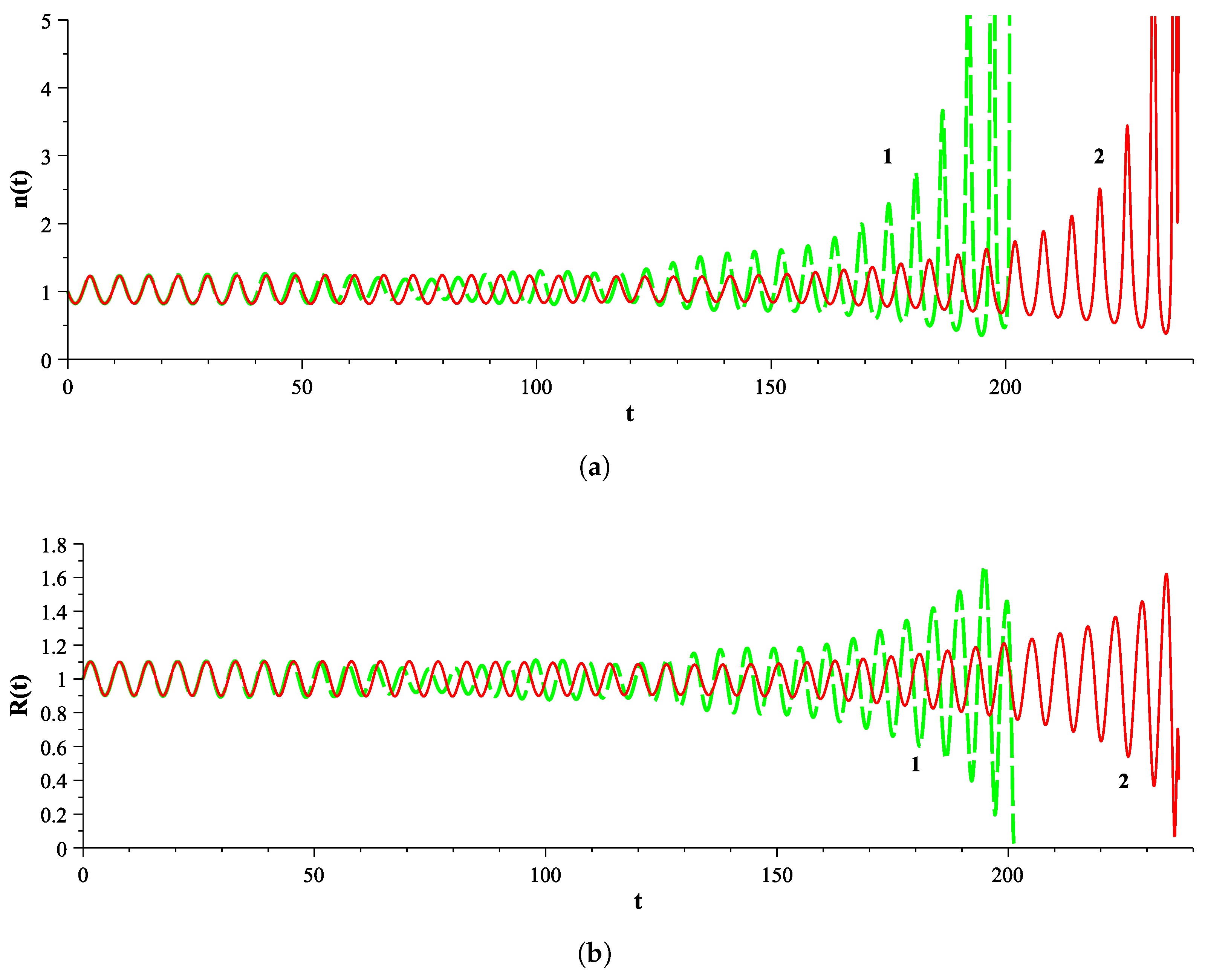
Figure 3 and
Figure 4 represent examples of the time evolution of the nonlinear oscillations for the (
) and (
) cases. The coupled oscillations of radial, azimuthal, and axial velocities are accompanied by a monotonic increase in their frequencies and amplitudes over the course of time. The growth of the amplitude of the velocity components provides large oscillations of the density
of the beam (see
Figure 4a), while the radius
is significantly decreased (see
Figure 4b). This means that our model works correctly until density collapse when it appears in the beam. In addition, functions
,
,
, and
evolve in time similarly to
; therefore, further on, we will represent
only as a radial velocity.
However, entirely opposite dynamics occur for values of
h relating to
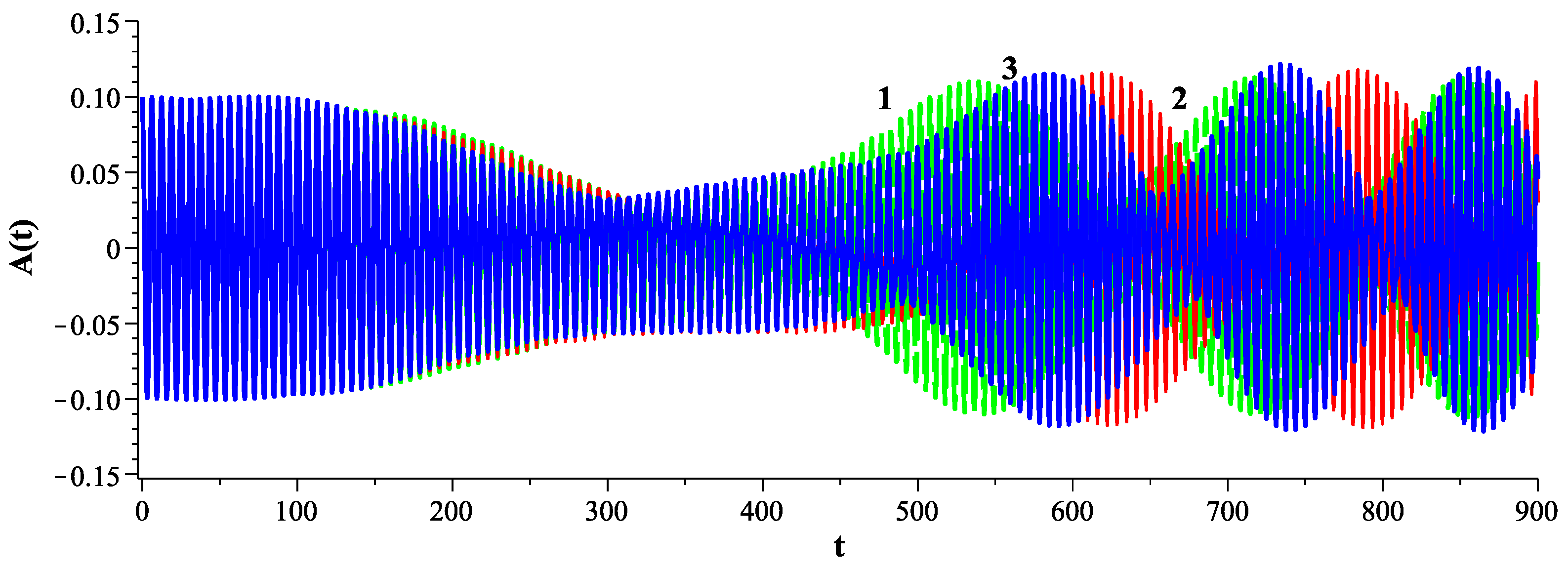
. One can see the typical behavior of the radial component of the field in
Figure 5. For
450, a decrease in the oscillations in both the radial and azimuthal components occurs, but later (
), wave trains (packets) are formed. Such behavior differs from the dependence in
Figure 3, where one can see a constant increase in the amplitude. It seems this process is connected with momentum transfer from these oscillations to the axial movement of the beam and it is saturates over time.
In the case of a dense medium (), the generation of oscillations of velocity and density increasing with time does not depend on the h values. This occurs with the increase in velocity amplitude for several orders, as shown in previous plots. It means that the needed conditions for the generation of electromagnetic radiation appear. The decrease in leads to an increase in the time of the singularity development.
It is also worth noting that the decrease in
leads to an exponential increase in time for all values in all cases (see
Figure 6). In addition, the increase in the amplitude of oscillations of different velocity components coincides with the increase in the frequency. This means that one can use the scheme as presented in
Figure 1 for the generation of electromagnetic radiation.
6. Discussion and Prospects
In the framework of a hydrodynamic approach, we have considered the amplification of coupled azimuthal, radial, and axial oscillations of finite amplitude for a charged-particle non-relativistic beam that is placed into crossed magnetic fields. Such a process is of interest for generating electromagnetic radiation; however, our consideration was restricted by the simplest assumption of cold, non-relativistic, rotating charged-particle beams without treating the intrinsic process of electromagnetic emission. That is, we have defined only the necessary conditions for generating radiation.
In the given schematic, the axial time-dependent component of the external magnetic field (here, only the harmonic law is used) generates a nonstationary azimuthal vortex electric field which provides momentum transfer from the field to the beam. This leads to azimuthal acceleration of the charged particles. In turn, the permanent radial component of the external magnetic field brings about the transfer of azimuthal momentum in the axial direction, which coincides with the beam’s direction. Thus, the energy exchange between the external field and the beam provides effective beam acceleration in both the axial and radial directions.
At the same time, this leads to an increase in natural electrostatic oscillations as functions of the density and velocity of the beam under a specific relation between the initial kinematic beam parameters. They are coupled both in the frequency and the amplitude of oscillations by relations (see Equations (19)). One can see that such a process occurs when the frequency of the external field is close to the frequency of the natural oscillations of the beam (see the curves in
Figure 3,
Figure 4,
Figure 5 and
Figure 6, where the difference between the frequency of the natural oscillations and the resonance frequency is less than 5%). Herewith, the present results demonstrate that the density of the beam increases over the course of time when the amplitudes of radial and axial velocities increase. This process accompanies the decrease in the radius of the beam over the course of time (see Equation (
22)), which indicates the possible implementation of the process in real accelerators where the transverse size of the beam is always limited by the size of the vacuum chamber.
In conclusion, we again would like to emphasize that the schematic sketched in
Figure 1 is a rude approach to the required configuration of external magnetic fields, which, however, makes it possible to discuss the expected effects. Therefore, we would like to touch on the real design of the technical implementation of the proposed idea.
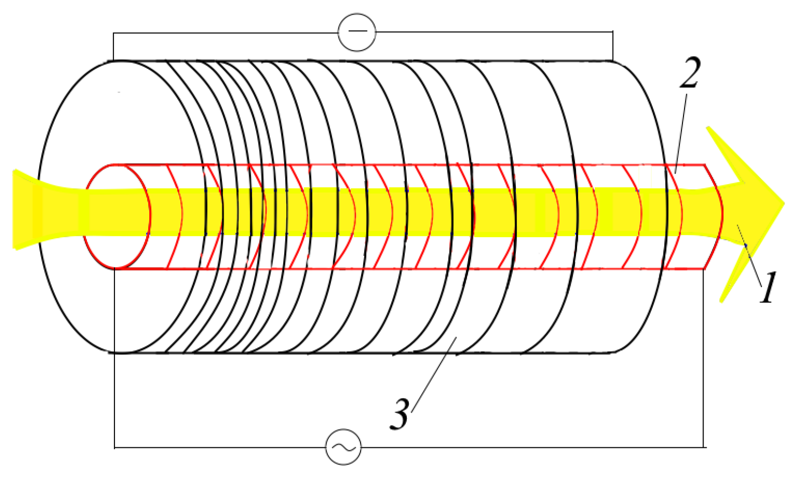
Instead of the schematic depicted in
Figure 1, we hope to use the scheme presented in
Figure 7. In the present case, the desired configuration of the outside magnetic field
is created by two coaxial coils with different geometric parameters; the outer coil has a winding that varies along its length, and the inner coil has a winding that is constant along its length. An alternating current is supplied to the inner coil, creating a time-dependent longitudinal magnetic field
that is fairly uniform along the
z-axis. A permanent current is supplied to the outer coil, which, due to the winding that varies along its length, creates a magnetic field that is constant in time but spatially non-uniform, with both axial
and radial
components whose values are determined by Equation (
1). The superposition of these fields gives
which may be a good enough approximation for the required configuration of the external magnetic field. In fact, this schematic is a development of the plasma accelerator schematic described in [
32,
33,
39]. It is worth noting that the radial component
can be enhanced if the outer coil has a conical shape; however, the analysis of such a system is very complex and we intend to discuss these questions in our forthcoming works.
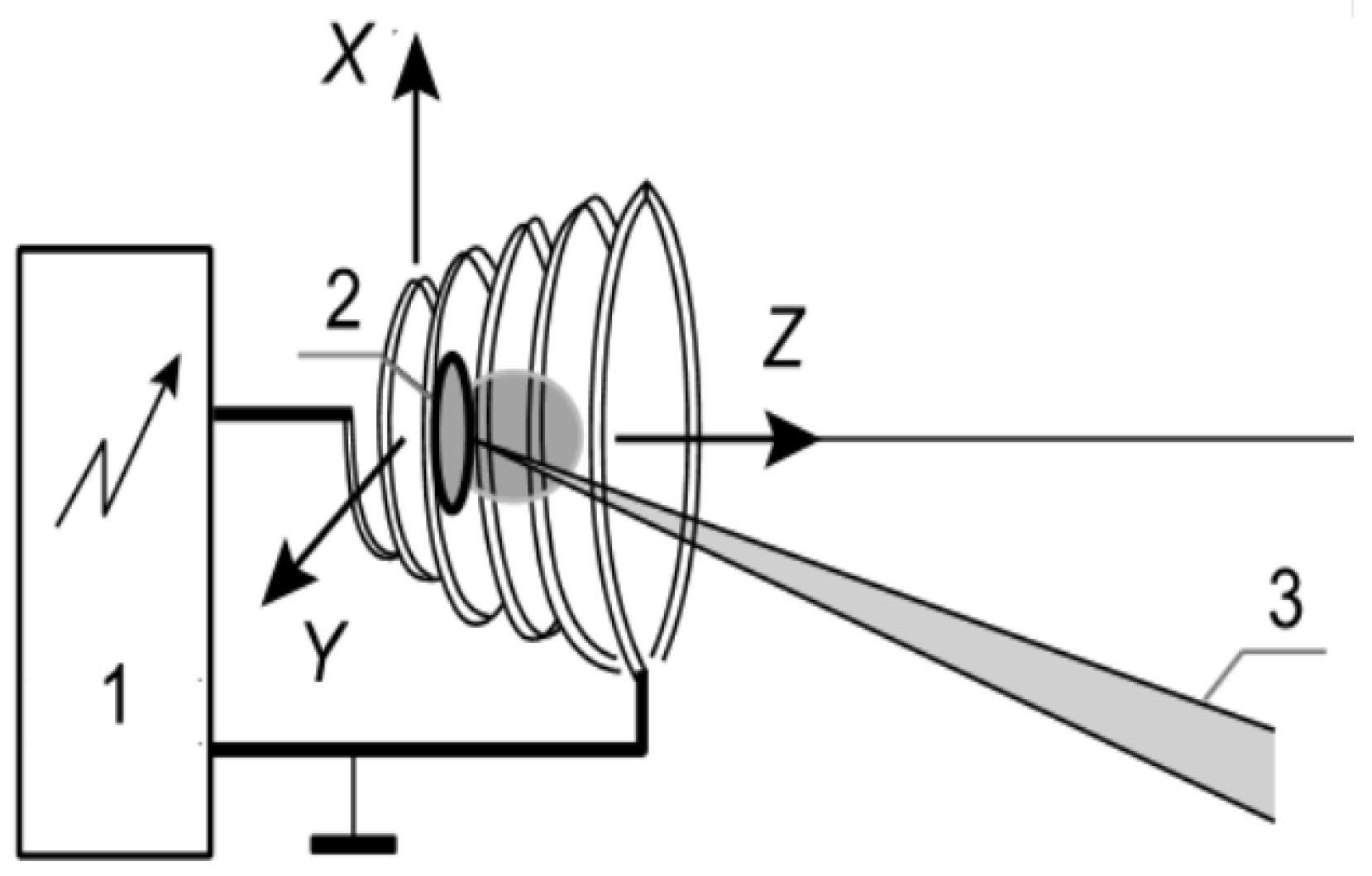
However, there are experimental studies [
59,
60] on a similar scheme, sketched in
Figure 8, which have principally exhibited the feasibility of implementing the discussed scheme. In these works, the required electric and magnetic fields were created by using a spiral line with a pulsed current in order to accelerate the plasma bunches consisting of both electrons and light ions (deuterons). The maximum energy of these ions reached a value of ∼100 keV. Therein, high-frequency electrical oscillations were observed in the antenna located on the axis of symmetry of the spiral.


