Article

Desorption of Implanted Deuterium in Heavy Ion-Irradiated Zry-2

1
Research Institute for Applied Mechanics, Kyushu University, Kasuga-kouenn, Kasugashi, Fukuoka 816-8580, Japan
2
Interdisciplinary Graduate School of Engineering Sciences, Kyushu University, Kasuga-kouenn, Kasugashi, Fukuoka 816-8580, Japan
3
Hitachi, Co., Ltd., Omika, Hitachshi, Ibaraki 319-1292, Japan
4
The Wakasa Wan Energy Research Center, Nagatani, Tsurugashi, Fukui 914-0192, Japan
*
Author to whom correspondence should be addressed.
Quantum Beam Sci. 2021, 5(2), 9; https://doi.org/10.3390/qubs5020009
Submission received: 22 March 2021 / Revised: 22 April 2021 / Accepted: 23 April 2021 / Published: 26 April 2021

Abstract

:
To understand the degradation behavior of light water reactor (LWR) fuel-cladding tubes under neutron irradiation, a detailed mechanism of hydrogen pickup related to the point defect formation (i.e., a-component and c-component dislocation loops) and to the dissolution of precipitates must be elucidated. In this study, 3.2 MeV Ni3+ ion irradiation was conducted on Zircaloy-2 samples at room temperature. Thermal desorption spectroscopy is used to evaluate the deuterium desorption with and without Ni3+ ion irradiation. A conventional transmission electron microscope and a spherical aberration-corrected high-resolution analytical electron microscope are used to observe the microstructure. The experimental results indicate that radiation-induced dislocation loops and hydrides form in Zircaloy-2 and act as major trapping sites at lower (400–600 °C) and higher (700–900 °C)-temperature regions, respectively. These results show that the detailed microstructural changes related to the hydrogen pickup at the defect sinks formed by irradiation are necessary for the degradation of LWR fuel-cladding tubes during operation.

1. Introduction

Hydrogen embrittlement of Zircaloy-2 is one of the main factors that limits the life of fuel rods in light water reactor (LWR) fuel-cladding tubes. Because the hydrogen centration exceeds the solid solubility of the metal, some hydrogen atoms are precipitated as hydride, causing hydride embrittlement. To understand how hydrogen pickup during operation influences the growth acceleration of the fuel rod, the effect of hydrogen on the neutron irradiation-induced microstructure should be studied. Hydrogen diffusivity under neuron irradiation is generally controlled by the trapping and de-trapping processes of hydrogen on the material. A dislocation loop is a radiation-induced defect cluster formed by the irradiation of neutrons [1,2], electrons [3,4], or charged particles [5,6,7,8,9,10]. Second-phase particles (SPPs) also form in Zircaloy-2 [11]. The size distribution of the SPPs and the chemical composition of the cladding tube affect the tube’s corrosion rate inside boiling water reactors (BWRs) [12,13,14,15,16,17]. However, these SPPs are unstable during neutron irradiation and undergo an amorphous transformation resulting in the decomposition and redistribution of the constituent elements the precipitates into defect sinks [15,16,17]. Ion irradiation has been used on nuclear materials in multiple studies because, unlike neutron irradiation, the displacement per atom (dpa) level, irradiation temperature, and other irradiation conditions can be precisely controlled [5,6,7,8,9,10].
In this study, 3.2 MeV Ni3+ ion irradiation is applied to Zircaloy-2 samples. The samples are injected with 5.0–30 keV D2+ ions to understand the trapping and de-trapping process of hydrogen on N3+ ion irradiated Zrycaloy-2. Thermal desorption spectroscopy (TDS) and conventional transmission electron microscopy (C-TEM) are conducted following the irradiation to evaluate the details of retention and desorption of the implanted deuterium and to identify the responsible traps.

2. Experimental Procedures

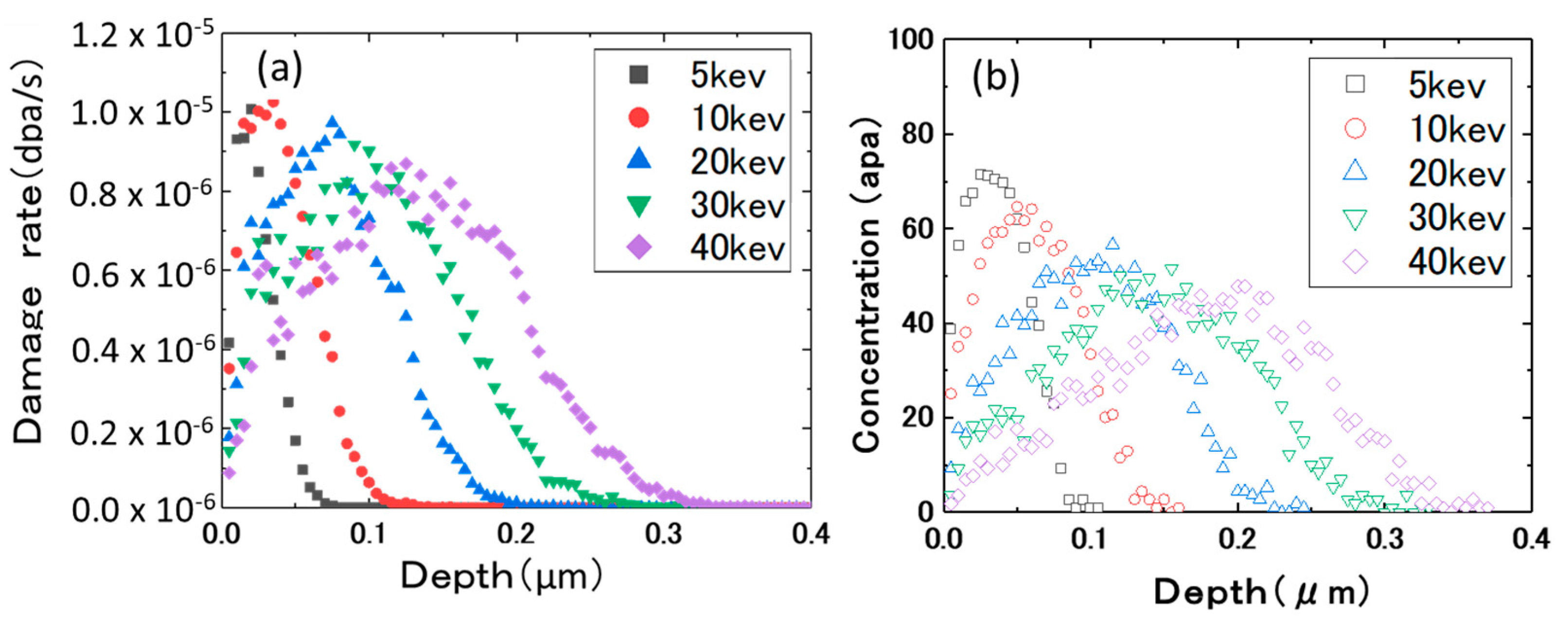
The Zircaloy-2 specimens were annealed at 630 °C for 2 h and subsequently air-cooled. Table 1 shows the results of the chemical analyses and the measurements of the hydrogen impurity levels of these specimens. The samples were irradiated at room temperature with 5.0–30 keV D2+ ions and 3.2 MeV Ni3+ ions by an ion implanter and a tandem accelerator at Kyushu University. Figure 1a shows the ion irradiation chamber (with a duo-plasma ion gun) used for the D2+ irradiation, and Figure 1b shows the specimen holder used for the D2+ and Ni3+ ion irradiation. Figure 2a shows the depth profile of the damage rate, and Figure 2b shows the concentration of D2+ ions irradiated at each accelerating voltage. The damage estimation was obtained from the Stopping and Range of Ions in Matter (SRIM) calculation [18], for which the threshold energy for displacement was assumed to be 40 eV. After irradiation at room temperature at a flux of 1.0 × 10¹⁸ ions/m2s, the samples were transferred into the vacuum chamber of the TDS apparatus. After they were evacuated, the specimens were held at room temperature for a period of time (less than 2 h) and TDS measurements were conducted. During the heating, with a ramping rate of 1 °C/s up to 900 °C, the thermal desorption of HD (mass = 3) and D2+ (mass = 4) were measured using quadrupole mass spectroscopy. The desorption rate was calibrated by a He standard leak and corrected the relative ionization efficiency.
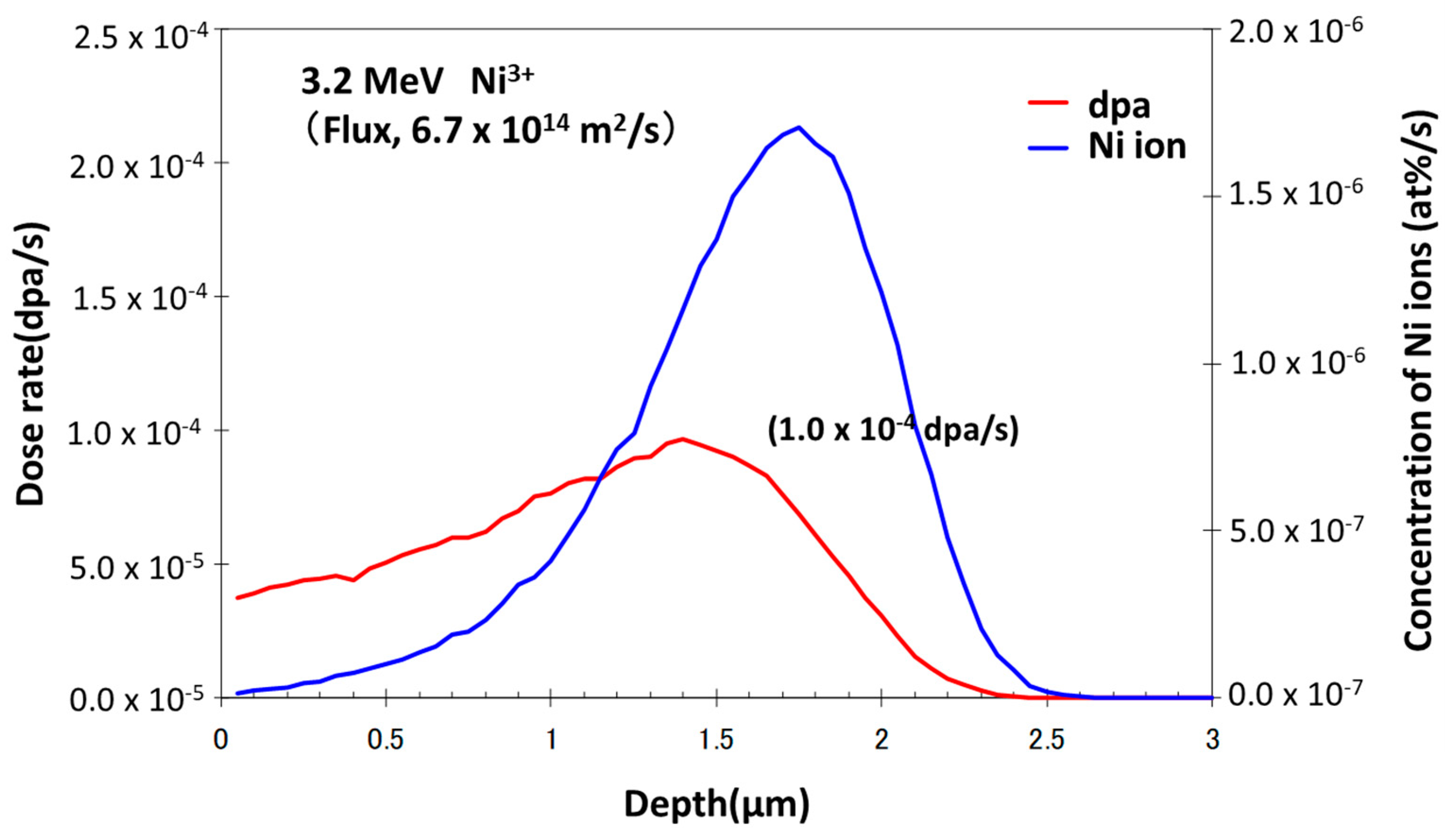
Figure 3 shows the damage distribution of the 3.2 MeV Ni3+ ions and the impurity concentration (Ni3+ ions) in the pure Zr following irradiation. The damage estimation was also obtained by the SRIM calculation. The samples for microscopy were thinned by the electropolishing method in which the electrolyte was a mixture of 50 mL perchloric acid and 950 mL acetic acid. During the thinning process, the electrolyte was held at −40 °C and the potential applied was 25 V.
The microstructure was observed before and after irradiation via C-TEM and using a spherical aberration (Cs)-corrected high-resolution analytical electron microscope (JEOL ARM200FC) operated at a voltage of 200 kV in a radiation-controlled area at Kyushu University.

3. Results and Discussions

3.1. Ion Dose and Energy Dependance of Thermal Desorption Behavior

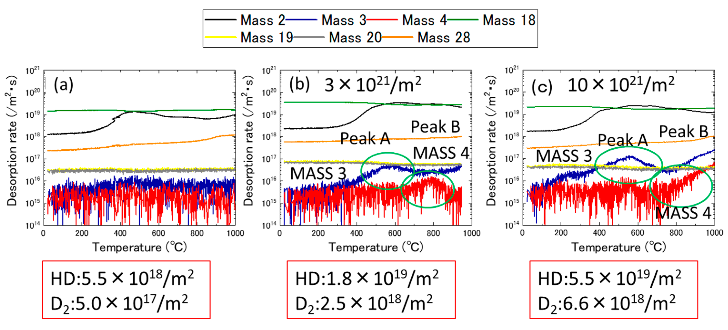
Figure 4 shows the dose dependance of the thermal desorption spectrum after 5.0 keV D2+ ion irradiation at room temperature. Figure 4a–c show the cases of unirradiated samples, samples radiated with 3.0 × 10²¹ ions/m2, and samples irradiated with 10 × 1021 ions/m2, respectively. As shown in Figure 4a, the desorption stages of HD (mass = 3) and D2 (mass = 4) were not detected prior to irradiation, but, after the D2+ ion irradiation, two major peaks at approximately 600 °C (mass = 3) and 800 °C (mass = 4) were detected. As demonstrated, the desorption stages were designated Peak A and Peak B on the lower temperature side. By increasing the irradiation dose from 3.0 to 10 × 1021 ions/m2, the total desorption of HD and D2 increased from 1.8 to 5.5 × 10¹⁹ ions/m2, and from 2.5 to 6.6 × 10¹⁸ ions/m2, respectively. The increasing rate was 3.1 for HD and 3.8 for D2. These values were nearly consistent with the increasing dose level values, particularly 3.3.
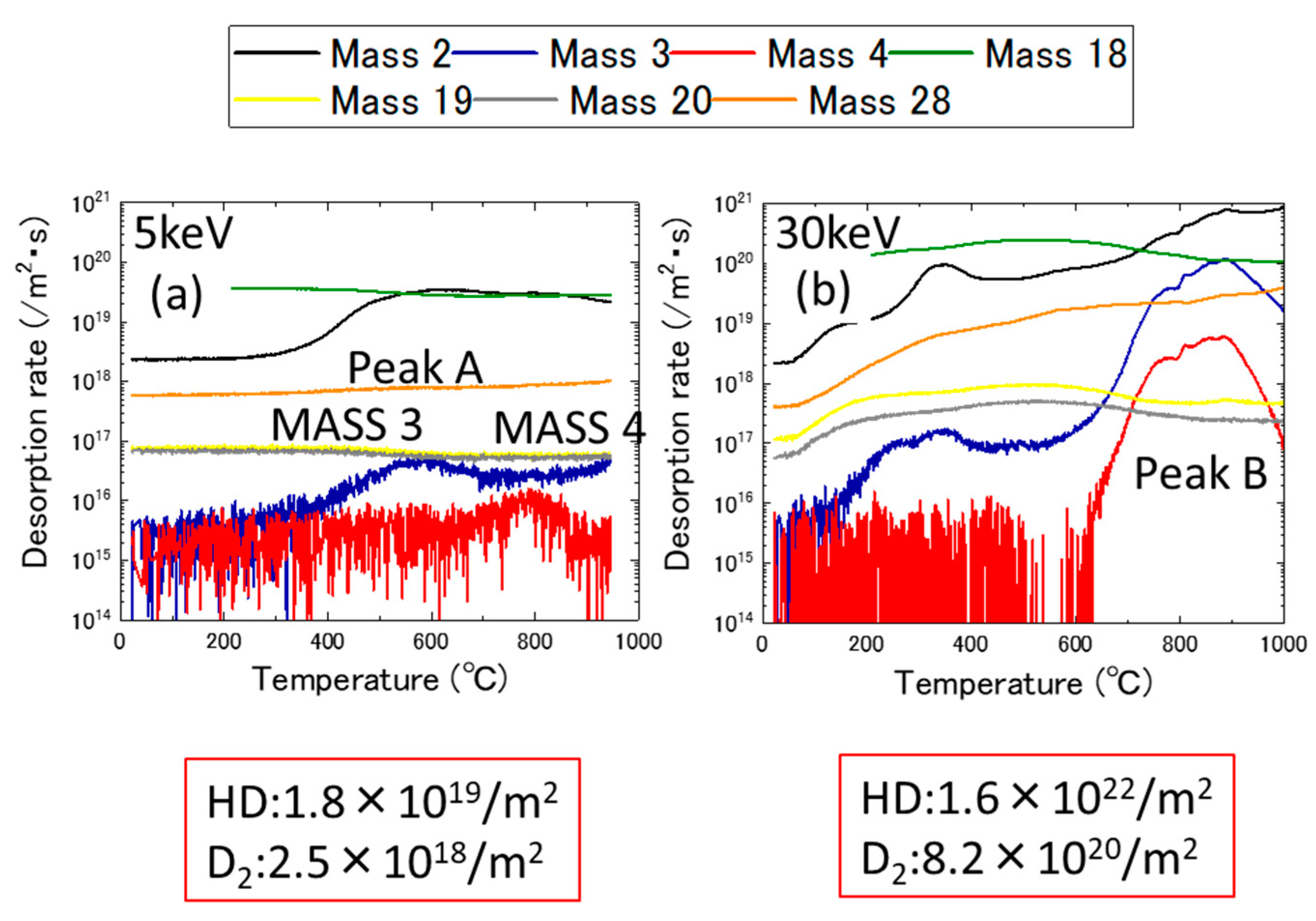
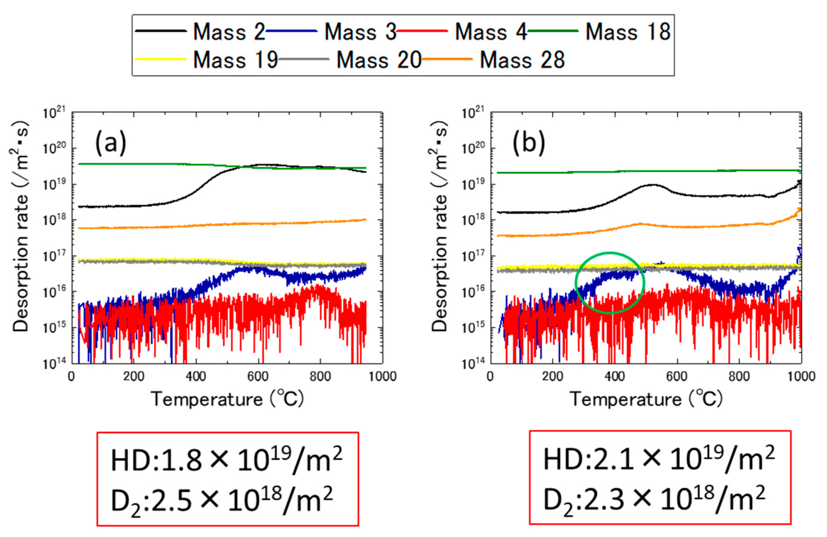
Figure 5a,b shows the ion energy dependance of the thermal desorption spectrum after the administration of 5.0 keV D2+ ions and 30 keV D2+ ions with a dose of 3.0 × 10²¹ ions/m2, respectively. Figure 5b, shows that Peak B became prominent when the ion energy increased to 30 keV. In this figure, the total desorption of deuterium after 30 keV ion irradiation was much higher than that of the sample after 5.0 keV. Since the implanted deuterium atoms do not stay at the same position which is calculated in Figure 2, they diffuse to the thick region of the sample during irradiation and hydrides are formed. In the case of 5.0 keV irradiation, more deuterium atoms were released from the specimen surface than at 30 keV. Detailed estimation of deuterium atom diffusion during irradiation and desorption is needed.
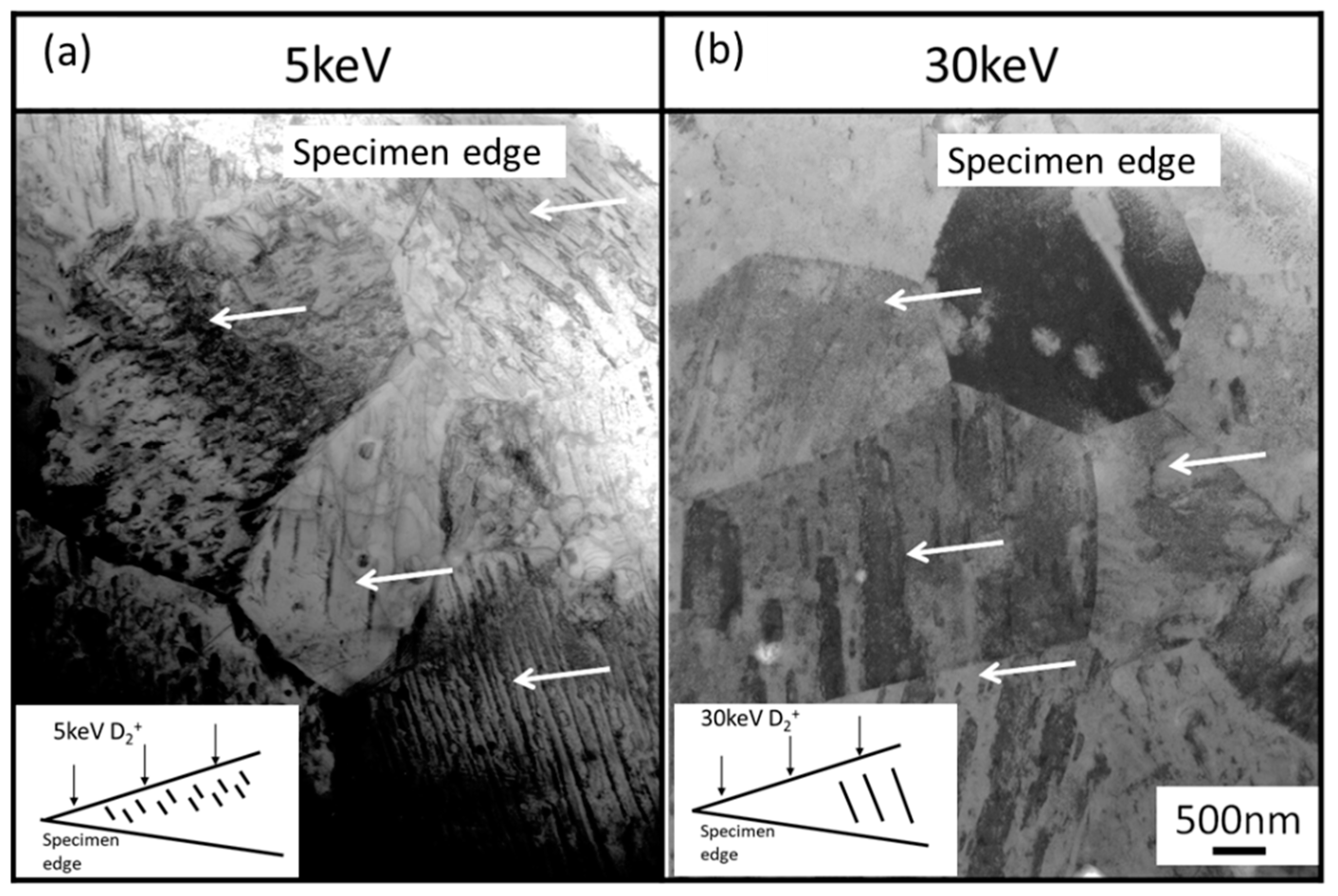
Figure 6a,b shows the microstructures of these samples. Hydrides were observed in the specimen’s edge region following irradiation at 5.0 keV (Figure 6a). However, hydride formation was only detected in the thick region of the C-TEM samples following irradiation at 30 keV (Figure 6b).
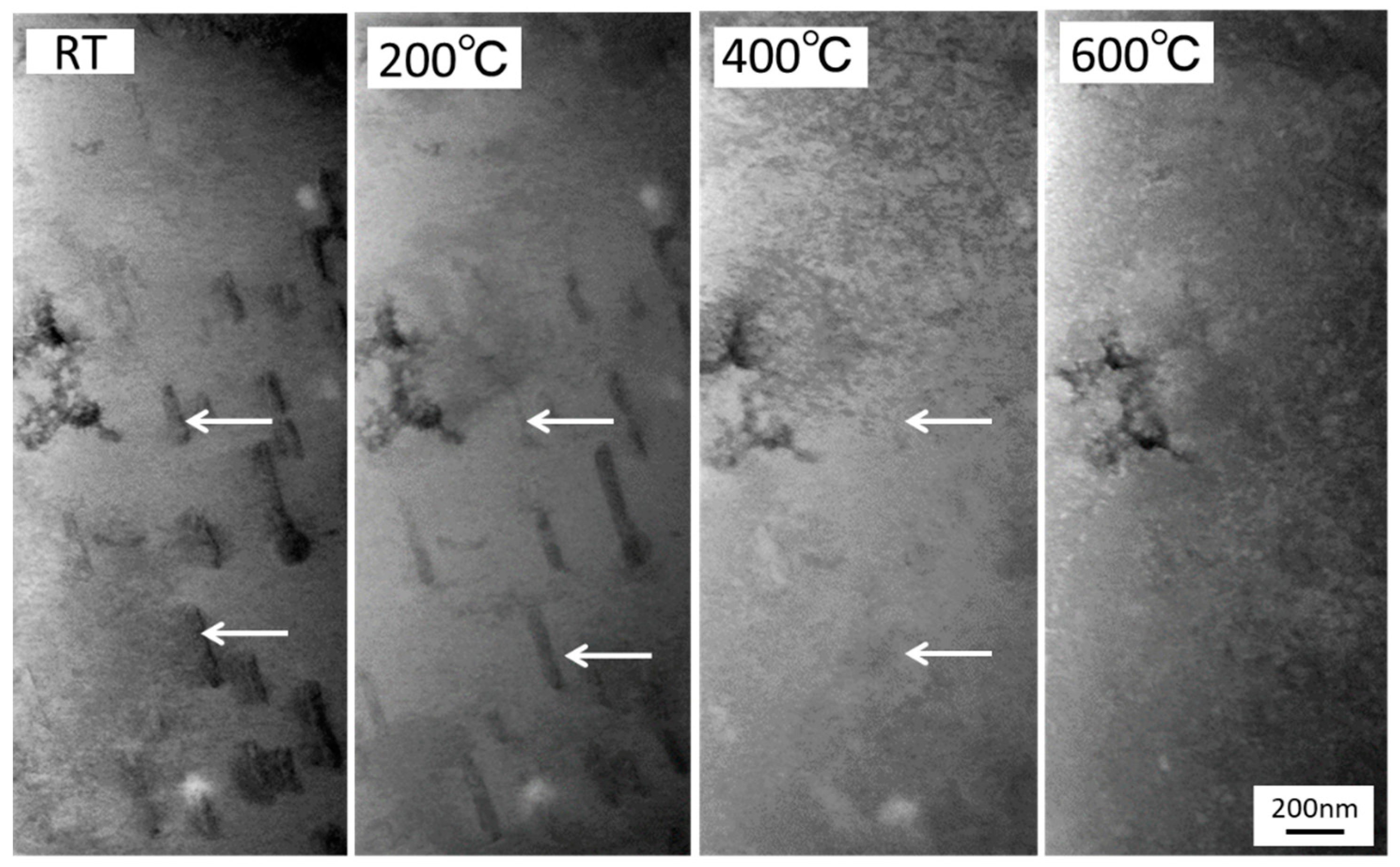
In our previous study of Zircaloy-2 [19], it was concluded that hydrides formed by annealing were stable up to 700 °C. The cross-sectional view of the sample showed that large hydrides were formed in the thick region of the samples. However, as Figure 6a shows, small hydrides formed in the specimen surface region by 5.0 keV D2+ ions irradiation were not stable in a higher temperature region (Peak B in Figure 5b). To investigate the thermal stability of these small hydrides in the surface region of the samples, the TEM samples was annealed at each temperature for 30 min, and the observation was conducted using a heating TEM holder. Figure 7 shows the thermal stability of these small hydrides, and they disappeared around 400 °C (in Peak A).

3.2. Effects of Nickel Ion Irradiation

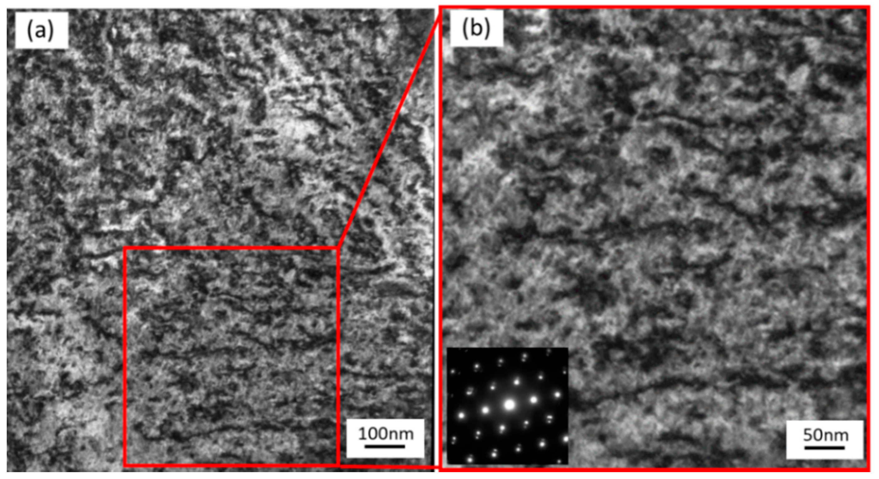
Figure 8a,b shows the microstructure after Ni3+ ion irradiation at room temperature. After the irradiation (up to 3.0 dpa), high-density dislocation loops (approximately 4.1 × 10²⁰ m−3) were detected. In the Zr alloys, interstitial-type dislocation loops (a-loops) and vacancy-type dislocation loops (c-loops) are known to form. Nakamichi et al. investigated the formation and growth process of a-loops in Zry-2 under electron irradiation using a high voltage electron irradiation (HVEM) [20]. Estimated migration energy for interstitial and vacancy were 0.17 eV and 1.0 eV, respectively. These dislocations formed in this study were identified as a-loops because of vacancy mobility at room temperature. A-loop formation was already saturated, and the loops were connected. Figure 9a,b shows the desorption spectrum before and after the 3.2 MeV Ni3+ ion irradiation at room temperature, respectively. A new stage appeared in the position close to Peak A because of the Ni3+ ion irradiation (up to 3.0 dpa).

3.3. Effects of Dislocations Formed by Cold Work

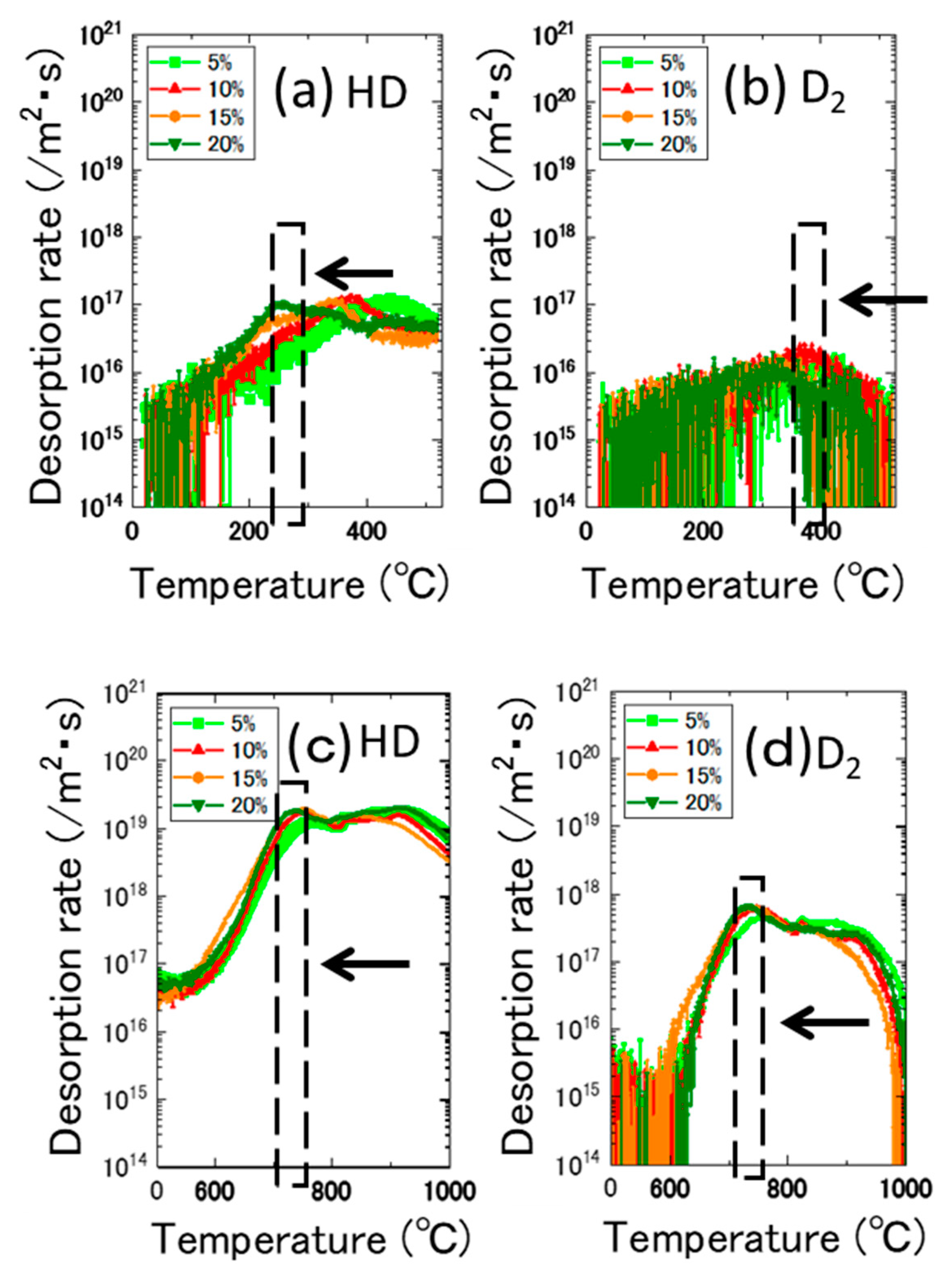
To determine the effects of the dislocations on the desorption spectrum, TDS experiments were conducted on cold-worked specimens in which dense dislocations were introduced. Figure 10a–d shows the desorption spectrum for the cold-worked specimens after irradiation with 5.0 keV D2+ ion to the fluence of 3.0 × 10²¹ ions/m2 at room temperature. In Figure 10a,b, the desorption stage A shifted to the lower temperature side when the level of cold work increased. However, the desorption stage B remained consistent when the level of cold work increased. Table 2 summarizes the total amounts of HD and D2. These values became saturated at 5% cold work and did not show any dependance on the level of cold work. Table 3 summarizes the desorption temperature range and their responsible trapping site for deuterium obtained by the present study.
As was discussed in Section 3.2, Ni3+ ion irradiation at room temperature induced a-loops into the samples. By increasing the level of cold work, stage A moved to the lower temperature side. Stage A corresponded to the recovery stage for weak trap sites as dislocation loops and hydrides formed in the surface region. Tangled dislocations (formed by cold work) and hydrides (formed in the thick region) contributed to stage B in the higher-temperature region.
In the Zircaloy-2 samples, a relatively large number (approximately 30 nm) of Zr2(Fe,Ni) precipitates were formed in the matrix [19]. Small Zr(Fe,Cr)2 precipitates were also found in the vicinity of the Zr2(Fe,Ni) precipitates. The number density of the Zr(Fe,Cr)2 precipitates was 2.0 × 10¹⁹ m−3 and that of the Zr2(Fe,Ni) precipitates was 3.2 × 10¹⁸ m−3. The stability of these SPPs is necessary at higher dose levels because it is at these levels that the formation of c-loops and the dissolution of the SPPs are known to occur simultaneously [17,19]. Among these SPPs, the Zr(Fe,Cr)2 precipitates are unstable during irradiation and undergo an amorphous transformation resulting in the decomposition and redistribution of other precipitates into defect sinks [15,16,17]. In this study, low-dose irradiation was chosen where phase stability of the SPPs was not essential. The irradiation dose was estimated to be approximately 18 dpa [21] at a burn-up of 50 GWd/t. This corresponded with the end of the life of the fuel rods for BWRs. The role of the redistributed precipitates and the number of c-loops formed at higher dose levels for hydrogen pickup are essential for the degradation of LWR fuel-cladding tubes during operation.

4. Summary

In this study, the details of retention and desorption of implanted deuterium were investigated and the responsible traps in irradiated Zircaloy-2 were identified. The thermal desorption of deuterium was conducted on Ni3+ ion-irradiated samples and cold-worked samples. The following conclusions have been drawn:
(1)
The desorption spectrum shows two major desorption stages (named Peak A and Peak B) in the temperature ranges of 400–600 °C and 700–900 °C, respectively.
(2)
As the thermal annealing experiments of ion-irradiated samples and cold-worked samples demonstrated, stage A corresponded to the recovery stage of weak trapping sites (i.e., the dislocation loops formed by irradiation and the hydrides that formed in the surface region of the specimens).
(3)
Stage B corresponds to the strong trapping sites explained by the tangled dislocations and hydrides that formed in the thick region of the specimens.

Author Contributions

Conceptualization, H.W.; TDS, Y.S. and K.T.; TEM, K.Y.; project administration, H.W.; funding acquisition, H.W., All authors have read and agreed to the published version of the manuscript.

Funding

This research received no external funding.

Acknowledgments

This work was supported by the Collaborative Research Program of Research Institute for Applied Mechanics, Kyushu University.

Conflicts of Interest

The authors declare no conflict of interest.

References

  1. Jonstsons, A.; Kelly, P.M.; Blake, R.G.; Farrell, K. Neutron Irradiation-Induced Defect Structure in Zirconium. ASTM STP 1979, 683, 46–61. [Google Scholar]
  2. Griffiths, M. A Review of Microstructure Evolution in Zirconium Alloys During Irradiation. J. Nucl. Mater. 1988, 159, 190–218. [Google Scholar] [CrossRef]
  3. Griffiths, M.; Loretto, M.H.; Smallman, R.E. Electron Damage in Zirconium. J. Nucl. Mater. 1983, 115, 313–332. [Google Scholar] [CrossRef]
  4. Griffiths, M.; Styles, R.C.; Woo, C.H.; Pillipp, F.; Frank, W. Study of Point Defect Mobilities in Zirconium During Electron Irradiation in a High-Voltage Electron Microscope. J. Nucl. Mater. 1944, 208, 324–334. [Google Scholar] [CrossRef]
  5. Lee, D.; Koch, E.F. Irradiation Damage in Zircaloy-2 Produced by High Dose Ion Bombardment. J. Nucl. Mater. 1974, 50, 162–174. [Google Scholar] [CrossRef]
  6. Tournadre, L.; Onimus, F.; Bechade, J.-L.; Gilbon, D.; Cloue, J.-M.; Mardon, J.-P.; Feaugas, X.; Toader, O.; Bachelet, C. Experimental Study of the Nucleation and Growth of C-Component Loops Under Charge Particle Irradiation of Recrystallized Zircaloy-4. J. Nucl. Mater. 2012, 425, 76–82. [Google Scholar] [CrossRef]
  7. Tournadre, L.; Onimus, F.; Bechade, J.-L.; Gilbon, D.; Cloue, J.-M.; Mardon, J.-P.; Feaugas, X. Toward a Better Understanding of the Hydrogen Impact on the Radiation Induced Growth of Zirconium Alloys. J. Nucl. Mater. 2013, 441, 222–231. [Google Scholar] [CrossRef]
  8. Yamada, S.; Kameyama, T. Observation of C-Component Dislocation Structures Formed in Pure Zr and Zr-base Alloy by Self-Ion Accelerator Irradiation. J. Nucl. Mater. 2012, 422, 167–172. [Google Scholar] [CrossRef]
  9. Shinohara, Y.; Abe, H.; Iwai, T.; Sekimura, N.; Kido, T.; Yamamoto, H.; Taguchi, T. In situ TEM Observation of Growth Process of Zirconium Hydride in Zircaloy-4 During Hydrogen Ion Implantation. J. Nucl. Sci. Technol. 2009, 46, 564–571. [Google Scholar] [CrossRef]
  10. Idress, Y.; Yao, Z.; Kirk, M.A.; Daymond, M.R. In situ Study of Defect Accumulation in Zirconium Under Heavy Ion Irradiation. J. Nucl. Mater. 2013, 433, 95–107. [Google Scholar] [CrossRef]
  11. Chemelle, P.; Knorr, D.B.; Van der Sand, J.B.; Pelloux, R.M. Morphology and Composition of Second Phase Precipitates in Zircaloy-2. J. Nucl Mater. 1983, 113, 58–64. [Google Scholar] [CrossRef]
  12. Taegtstrom, P.; LimBaeck, M.; Dahlbaeck, M.; Andersson, T.; Pettersson, H. Effects of Hydrogen Pickup and Second Phase Particle Dissolution on the in-Reactor Corrosion Performance of BWR Cladding. ASTM STP 2002, 1423, 96–118. [Google Scholar]
  13. Valizadeh, S.; Ledergerber, G.; Abolhassani, S.; Jaedernaes, D.; Dahlbaeck, M.; Mader, E.V.; Zhou, G.; Wright, J.; Hallstadius, L. Effects of Secondary Phase Particle Dissolution on the In-Reactor Performance of BWR Cladding. STM STP 2011, 1529, 729–753. [Google Scholar]
  14. Sundell, G.; Thuvander, M.; Tejland, P.; Dahlbaeck, M.; Hallstadius, L.; Andren, H.-O. Redistribution of Alloying Elements in Zircaloy-2 After In-Reactor Exposure. J. Nucl. Mater. 2014, 454, 178–185. [Google Scholar] [CrossRef] [Green Version]
  15. Griffiths, M.; Gilbert, R.W.; Carpenter, G.J.C. Phase Instability Decomposition and Redistribution on Intermetallic precipitates Zircaloy-2 and -4 During Neutron Irradiation. J. Nucl. Mater. 1987, 150, 53–66. [Google Scholar] [CrossRef]
  16. Griffiths, M.; Gilbert, R.W.; Fidleris, V.; Tucker, R.P.; Adamson, R.B. Neutron Damage in Zirconium Alloys Irradiated at 644 to 710K. J. Nucl. Mater. 1987, 150, 159–168. [Google Scholar] [CrossRef]
  17. Griffiths, M.; Gilbert, R.W. The Formation of c-Component defects in Zirconium Alloys During Neutron Irradiation. J. Nucl. Mater. 1987, 150, 169–181. [Google Scholar] [CrossRef]
  18. Ziegler, Z.F. SRIM–The Stopping and Ranges of Ions in Matter. Available online: http://www.strim.org (accessed on 13 November 2019).
  19. Watanabe, H.; Takahashi, K.; Yasunaga, K.; Wan, Y.; Aono, Y.; Maruno, Y.; Hashizume, K. Effects of an Alloying Element on a C-Component Loop Formation and Precipitate Resolution in Zr Alloys During Ion Irradiation. J. Nucl. Sci. Technol. 2018, 55, 1212–1224. [Google Scholar] [CrossRef]
  20. Nakamichi, M.; Kinoshita, C.; Yasuda, K.; Fukada, S. Formation and Growth Process of Dislocation Loops in Zircaloys under Electron Irradiation. J. Nucl. Sci. Technol. 1987, 34, 1079–1086. [Google Scholar] [CrossRef]
  21. Sonoda, T.; Sawabe, T.; Kitajima, S.; Nishikawa, N. Radiation Damage Accumulation and Dissolution of Second Phase Particles in Zircaloy-2 by means of Ion Accelerator. In Proceedings of the WRFPM 2014, Sendai, Japan, 14–17 September 2014; p. 100091. [Google Scholar]
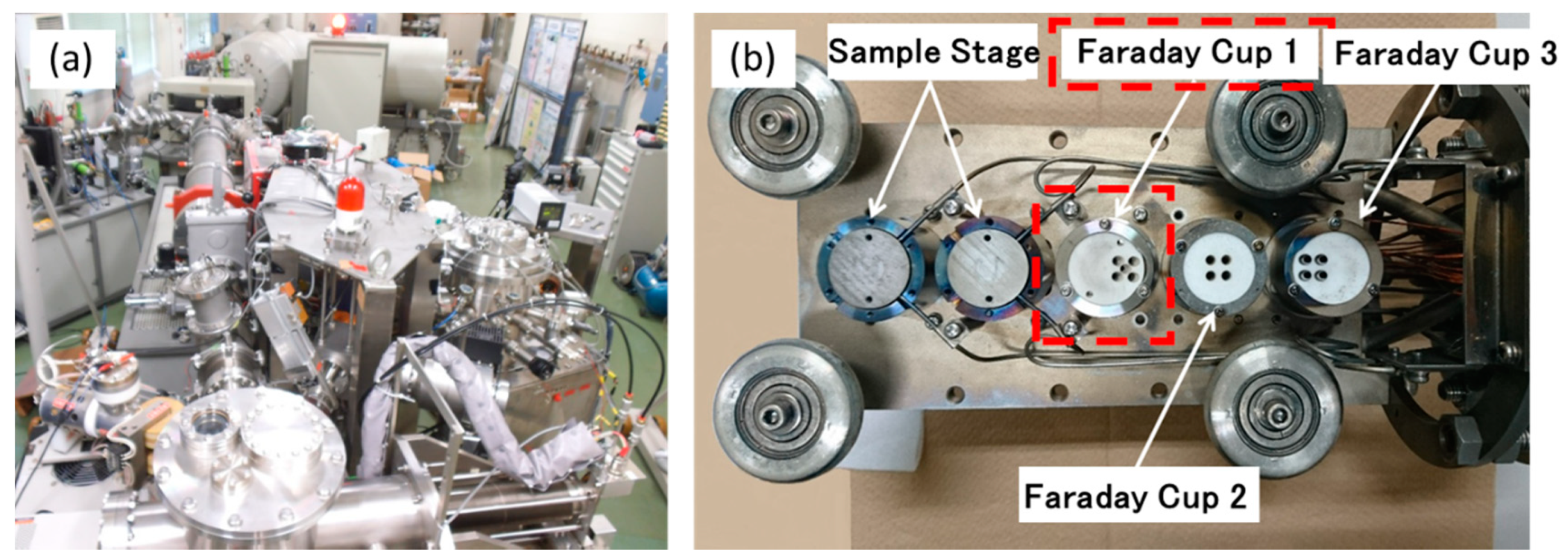
Figure 1. The triple ion beam facilities at RIAM Kyushu University: (a) tandem-type accelerator attached with two ion guns: terminal voltage 1.0 MeV and (b) specimen holder for ion irradiation.
Qubs 05 00009 g001
Figure 2. The depth profile of the damage rate (a) and the concentration of D+ at 3.0 × 10²¹ ions/m2 (b) in the case of each accelerating voltage.
Qubs 05 00009 g002
Figure 3. The SRIM calculation [18,19] of the damage distribution and the concentration of Ni3+ atoms in Zr irradiated by Ni3+ ions at 3.2 MeV. The values are estimated in the case of 6.7 × 10¹⁴ ions/m2s.
Qubs 05 00009 g003
Figure 4. The dose dependance of the thermal desorption spectrum after 5.0 keV D2+ ion irradiation at room temperature: (a) before irradiation, (b) 3.0 × 10 21 ions/m2, and (c) 10 × 1021 ions/m2.
Qubs 05 00009 g004
Figure 5. The energy dependance of the thermal desorption spectrum after the ion irradiation with a dose of 3.0 × 10²¹ ions/m2 at room temperature: (a) 5.0 keV and (b) 30 keV.
Qubs 05 00009 g005
Figure 6. The energy dependance of the microstructure after the ion irradiation with a dose of 3.0 × 10²¹ ions/m2 at room temperature: (a) 5.0 keV and (b) 30 keV (the arrows show the hydrides formed by irradiation).
Qubs 05 00009 g006
Figure 7. The thermal stability of the small hydrides formed in the surface region (30 keV, 3.0 × 10²¹ ions/m2 at room temperature). The hydrides (shown by arrows) disappeared at 400 °C.
Qubs 05 00009 g007
Figure 8. (a,b) The dislocation loops formed after 3.2 MeV Ni3+ ion irradiation at room temperature. The irradiation dose was 3.0 dpa. Ion irradiation and TEM observation were conducted perpendicular to the <C> direction.
Qubs 05 00009 g008
Figure 9. The thermal desorption spectra (a) before and (b) after 3.2 MeV Ni3+ ion irradiation with a dose of 3.0 dpa at room temperature.
Qubs 05 00009 g009
Figure 10. The amount of cold work dependance of the thermal desorption spectrum after 5.0 keV D2+ ion irradiation at room temperature: (a,b) lower temperature region and (c,d) higher-temperature region.
Qubs 05 00009 g010
Table 1. Chemical composition of the materials used in the present study (wt%).
SnFeCrNiH
(wtppm)
Zr
Zircaloy-21.380.150.090.0546Bal.
Table 2. Total desorption of HD and D2 obtained in cold-worked samples.
Cold Work (%)HD (m−2)D2(m−2)
01.8 × 10192.5 × 1018
54.0 × 10211.0 × 1020
103.8 × 10219.7 × 1019
154.2 × 10219.5 × 1019
204.8 × 10219.9 × 1019
254.0 × 10211.3 × 1020
Table 3. Desorption temperature range and their responsible trapping site for deuterium.
StageTemp. (°C)Type of Trapping
Stage A400–600Weak Trap
(dislocation loop, hydrides formed in surface region)
Stage B700–900Strong Trap
(tangled dislocation, hydrides formed in thick region)
Publisher’s Note: MDPI stays neutral with regard to jurisdictional claims in published maps and institutional affiliations.