Article

Three-Dimensional Hydrodynamic and CFD Modeling of a Tidal Barrage Power Plant without Sluicing in Buenaventura, Colombia

by
Daniel Parrado
1,2 and
Juan Gabriel Rueda-Bayona
1,2,*
1
Natural and Environmental Resources Engineering School (EIDENAR), Faculty of Engineering, Universidad del Valle, Cali 760042, Colombia
2
INCIMAR Institute of Marine Sciences and Limnology, Universidad del Valle, Cali 760042, Colombia
*
Author to whom correspondence should be addressed.
Infrastructures 2024, 9(8), 127; https://doi.org/10.3390/infrastructures9080127
Submission received: 3 May 2024 / Revised: 9 July 2024 / Accepted: 15 July 2024 / Published: 3 August 2024

Abstract

:
Recent research revealed the potential of tidal energy in the central coastal region of the Colombian Pacific. Buenaventura City, located in the Valle del Cauca department in Colombia, has an important opportunity to develop tidal power technologies near its marine coastal areas. This research implemented a 3D hydrodynamic model for simulating the hydrodynamics of the Buenaventura Bay to provide data as input for evaluating the hydraulics of a tidal barrage without sluicing through CFD modeling. According to the results, the velocities across the gates during Syzygy (April 2021) showed impressive velocities between 9 and 11 m/s, which suggest a high possibility of producing electricity through tidal turbines. The mean behavior of velocities in the gates pointed to values of 3 and 5 m/s in most of the cases. The results during the Stoa condition were interesting because flow velocities higher than 1 m/s were not expected. This is promising because the plant might produce electricity even during the Stoa condition. For the first time, the results of this research suggest that there exists a high possibility of implementing tidal barrage plants in Buenaventura City, Colombia.

1. Introduction

Renewable energy sources are alternatives to fossil fuels and can help decarbonize economies and reduce GHG worldwide emissions [1], and marine energies like tidal power technology are one of them [2]. Recent research has revealed the potential of tidal energy in the central coastal area of the Colombian Pacific [3,4]. Buenaventura City, located in the Valle del Cauca department in Colombia, has an important opportunity to develop tidal power technologies near its marine coastal regions.
Tidal power is classified into two main groups according to the mechanism of electricity generation. The first are stream turbines, which utilize the hydrokinetic energy of tidal currents to produce electricity. The second are tidal barrages (tidal ranges), a technology that uses dams and gates to produce electricity through bulb or Kaplan turbines. The tidal range is the most matured according to its technology readiness level (TRL), which is 9, and tidal barrage plants have been operating since the 1960s [5]. However, tidal barrage plants require specific coastal and oceanographic characteristics [6] and face high investment costs and environmental risks, which have limited their worldwide application [7,8].
Recent studies have deepened the understanding of the impacts and opportunities of tidal range technology, considering societal needs and sustainable and responsible interaction with natural habitats [9]. Tidal barrages not only provide benefits in terms of electricity, better connectivity for transportation [10], tourism, and fishing [11], but also serve as a form of prevention of natural disasters (e.g., flooding) [10]. Other theoretical studies [8] have warned about the possible negative impacts triggered by tidal range plants, i.e., fish appear to be disoriented and at greater risk of predation downstream the dam after crossing the turbine passages [12], underwater noise [13], a reduction in the tidal water level range by about a half [14], the loss of intertidal areas following the construction of barrages [15], erosion and local scour due to sluices and chamber discharges [16], modifications in water quality dynamics, e.g., changes in the sediment transport balance [17], increases in nutrient concentrations, and decreases in suspended sediment, provoking eutrophication [18]. However, now-operating tidal range power plants, like Siwha in South Korea [6], have solved the problem of the unbalanced water quality dynamics generated by a prior embankment reservoir utilized for agricultural and irrigation water for the region.
The review of tidal range plants performed by Neil et al. [19] in 2018 analyzed the past perspectives and future challenges of the technology. Neil et al. noted that the La Rance tidal barrage was the first fully operational tidal plant in 1966, which consists of a 720 m-long barrage and 22 km2 of impounds. The plant has 24 bulb turbines with a rated power output of 240 MWh (10 MWh each), and an annual energy production of 480 GWh. Later, in 1968, the Kislaya Guba tidal plant in Russia with an installed capacity (rated power) of 1.7 MWh was built. In 1984, the Annapolis Royal Generating Station in Nova Scotia, Canada, began operations, consisting of a single Straflo turbine with a peak power output of 20 MW on the ebb tide only.
Later, in 1985, the Jiangxia tidal range plant was built in China and began to operate; the plant has six bulb turbines that operate bidirectionally with an installed capacity of 3.9 MW for each turbine. The most recent and largest tidal range plant was built in 2011, composed of 10 25.4 MW bulb turbines, which allow for a total capacity of 240 MW. The Sihwa tidal plant operates in a mean tidal range of 5.6 m, with a spring tidal range of 7.8 m and a working basin area of 30 km2 [19]. Neil et al. [19] reviewed theoretical studies providing information on potential tidal range plants worldwide. The review pointed to 1 location in South America (Argentina), 8 new places in North America (Mexico, USA, and Canada), 10 in Great Britain, 2 in India, 2 in Australia, 2 in South Korea, and 4 in the former Soviet Union. The lowest and highest tidal ranges reported in the study were 4.5 m and 12.4 m in Cheonsu (South Korea) and Cobequid (Canada), respectively.
Numerical modeling as a tool for locating potential areas for tidal range power plants has been an alternative approach in the pre-feasibility stages of energy projects. Zero-dimensional modeling is a parameterized numerical method that requires a few input data for simulating the overall performance of a tidal range plant, i.e., the known tidal conditions, the plan operation sequence, and the formulae representing the hydraulic structures [19]. Several applications of 0D modeling in small lagoons and barrages have been found in recent research [20,21,22,23]. One-dimensional modeling vertically and horizontally integrates the flow in an estuary, which eases the simulation of tidal lagoons and barrages and their effects on the hydrodynamics [21]. The results of 1D modeling must be managed with caution because its applicability is limited to small lagoons like Swansea Bay [24].
The most known 2D hydrodynamic models are utilized for large and regional scale applications and are based on depth-averaged (2D) shallow water equations (SWEs), which are derived from depth-integrating Navier–Stokes (NS) equations; the 3D models omit horizontal–vertical integration for the full solving of the NS equations. Examples of numerical models in tidal energy coastal studies are ADCIRC [22], Telemac-2D [25], EFDC [26,27], and Delft3D [3]. The 3D hydrodynamic CFD (computational fluid dynamics) model is an alternative for full representation of the fluid dynamics in complex control volume [28] and transport processes. As Neil et al. [19] mentioned, CFD use for tidal range plant applications is very scarce and has been limited to laboratory scale flows across gates and turbines [29,30].
Recent studies in Colombia have revealed the potential of tidal energy for electricity generation [3,4] because of the mean tidal range (3.5 m) and tidal current velocities between 0.5 and 2 m/s within the Buenaventura Bay. Several theoretical studies exist showing the potential of implementing tidal range plants with a tidal range of about 4 m, e.g., Garorin and Cheonsu (South Korea), and the largest tidal plant now operating (Sihwa Lake) has a mean tidal range of 5.6 m. In this sense, tidal range plants may operate in a meso-scale tidal regime (3–6 m) with an appropriate base working area. Buenaventura Bay has these tidal and geomorphological characteristics and would be a candidate for developing new tidal range plants in Colombia.
Considering the need for expanding the engineering data, the growing interest in marine renewables, the lack of open information on potential areas for implementing tidal range (barrage) plants in tropical areas like Colombia, and the commitment of this country to a clean and fair energy transition, this research points to Buenaventura Bay as a candidate for implementing the first tidal power plant in Colombia.

2. Materials and Methods

This research implemented a 3D hydrodynamic model (Delft3D) [31] to simulate the circulation of Buenaventura Bay (Figure 1), and it was validated and calibrated with in situ data (i.e., currents, water levels, weather, and bathymetry) provided by the General Maritime Directorate of Colombia (DIMAR). Marine current data at 5-min time intervals were retrieved from an ADCP profiler installed at the seafloor, and the water level data were obtained from a local tidal station. The meteorological data, such as wind, temperature, and more, came from a local station close to the DIMAR. The bathymetry data were collected in 2021 along the navigable access channel, as well as from other areas within the bay. More information on the data measurements can be found in [3].
The temperature and salinity information was obtained from in situ data measured and stored in the REDCAM database (https://siam.invemar.org.co/redcam-consulta-datos, accessed on 10 September 2023). Also, to simulate the hydrodynamics of the tidal power plant, a CFD model was configured using Autodesk Inventor Professional software version 2024 (www.autodesk.com, accessed on 10 September 2023). The CFD model uses the Navier–Stokes and energy equations to determine the hydrodynamics. The model is capable of free-surface modeling and uses the Eulerian volume-of-fluid (VOF) approach. The advection of the free surface is determined with the following equation:
F τ + V F = 0
where F is the fill fraction, used to determine which elements are filled with fluid and which elements are not; when F = 0, the element is empty, when F = 1, the element is filled with liquid. V is the liquid velocity field and is determined by the incompressible Navier–Stokes equations. On the free surface (fluid–gas interface) the static gage pressure = 0, and gas-filled regions are considered empty elements; these empty elements are omitted for hydrodynamic solutions.
The setup model parameters were taken from the research of Rueda-Bayona et al. [3]. The hydraulic modeling options were tested in the flow module of Delft3D by simulating the effects of hydraulic structures (gates and dams). Several runs were performed, and the results did not evidence significant changes in the energy balance of the operational area of the tidal barrage. According to this, it was observed that the hydraulic simulation must be performed using a different numeral approach than the finite difference method of Delft3D. First, the hydrodynamic modeling of HECRAS was implemented (www.hec.usace.army.mil/software/hec-ras/, accessed on 10 September 2023). The model is 2D with a 2 × 2 m mesh, set in a transient regime, with 5 × 5 gates and boundary conditions defined by the water level data. The HECRAS model adequately represents the dynamic flow field of currents and the differences in the gravitational potential energy on both sides of the reservoir. However, due to the software limitations to estimate velocities as a function of flow depth, the velocity results at the chambers were not representative for the purpose of this study.
The mesh grid cell size of Buenaventura Bay in the Deflt3D model was 40 m, due to the high extension of the bay and the high computational cost. This cell size was approximate to simulate the local hydraulics of the tidal barrage, but important for providing the overall flow pattern for the CFD model. The hydraulic modeling options were tested in the flow module of Delft3D, simulating the effects of the hydraulic structures as gates and dams. Several runs were performed, and the results did not evidence significant changes in the energy balance of the operational area of the tidal barrage. Because of this, the hydraulic option of gates in Delft3D did not produce the expected hydrodynamic results. The mesh was built with cell sizes of 40 m × 40 m, with 7 layers for the “z” axis and uniform thickness. The bathymetric points were interpolated using the average value of the near-point method, assigning depths for each grid cell.
The simulations were run in the Delft 3D flow module using a coordinate cartesian system, with a time horizon of 1 year starting from 1 January 2021 to 1 January 2022. The model included the components of salinity and water temperature, with values of 28 and 28 °C, respectively. For the flow boundary condition, an open water level boundary was set, with an alpha reflection parameter of 100 S2 and constant transport conditions over the time. The density of the water was set to 1020 kg/m3, and for the bottom roughness model, the Chezy formula was used, with a value of 65 m1/2/s and a free sliding condition at the walls. The horizontal viscosity of the flow was modeled with a uniform condition of 1 m2/s and horizontal diffusivity of 10 m2/s, using the 3D k-epsilon turbulence model. The Thin Dams model configuration was used to represent the reservoir within the bay, and the different gate configurations that the Delft 3D model allows were tested.
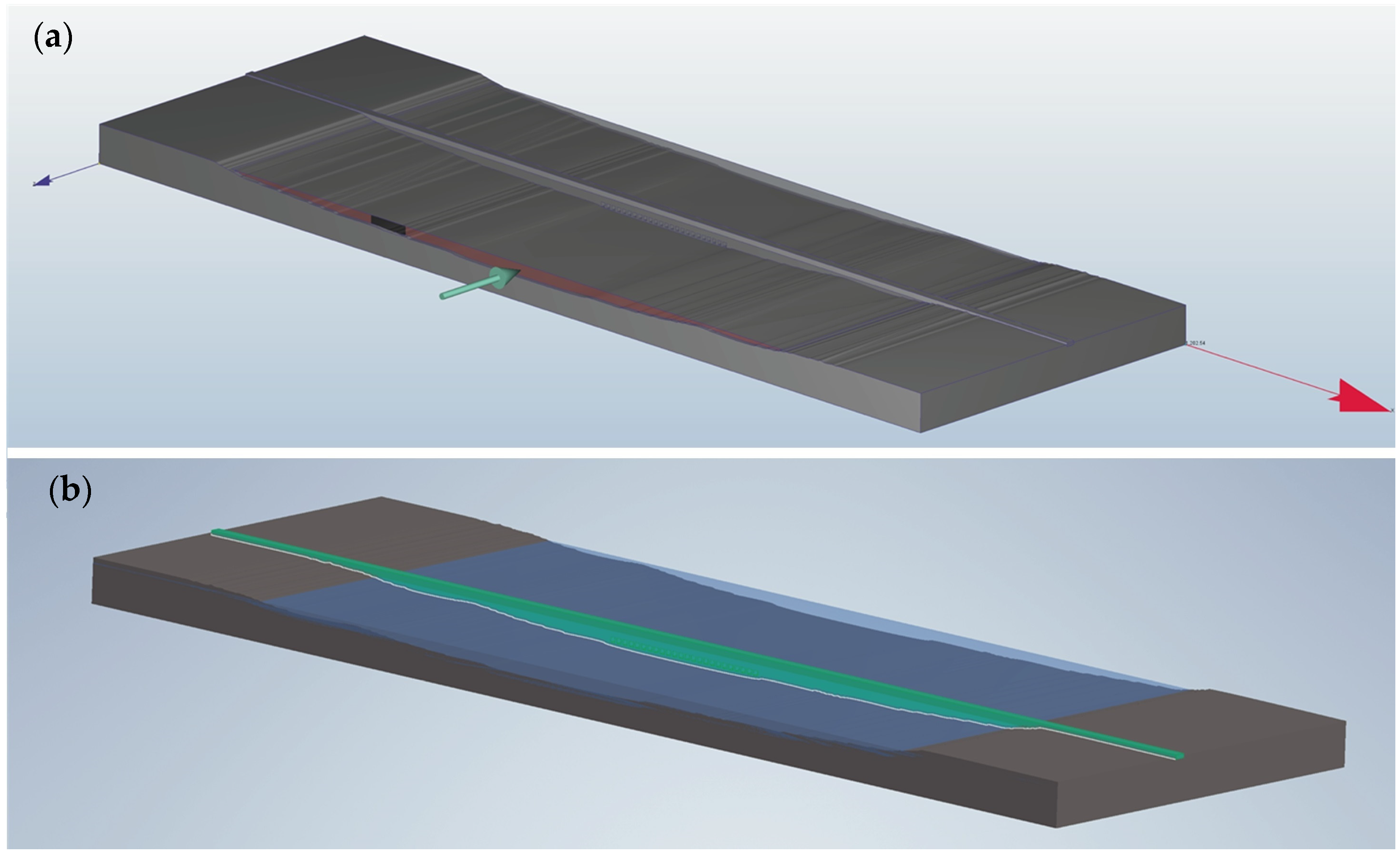
Consequently, we decided to implement the CFD Autodesk model (Figure 2) to generate the expected results when the flow velocity increases because of the reduction area generated by the chambers of the tidal plant. To validate the CFD results, we used the theoretical formula (Equation (2)) of Angeloudis [32], which estimates the flow velocity across submerged gates with different hydraulic heads upstream and downstream:
Q = C D A 2 g H
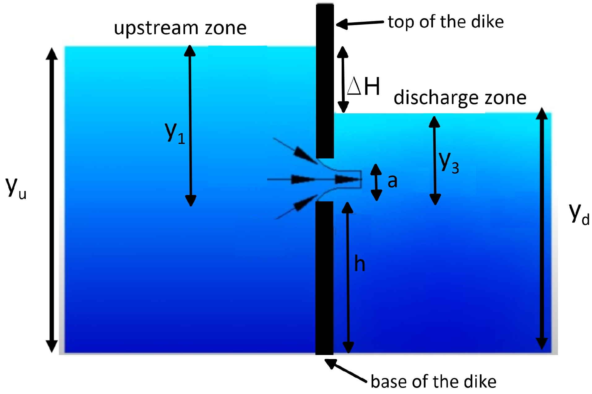
where Q is the flow, A is the aggregate cross-sectional flow area (m2) of the chamber, g is the gravity constant (9.81 m/s2), and H = y 1 y 3 is the difference between the upstream and downstream water depth. CD is the discharge coefficient, which was obtained from the charts of [33,34] and numerically validated in [35]. The charts provide the CD considering the ratio between y 1 / a and y 3 / a . In Figure 3, the scheme of a gate opening is shown, where y 1 and y 3 are the water depths upstream and downstream, respectively, and a is the gate opening.
For this study, the hydraulic chamber of the tidal barrage was fully filled permanently to allow for the operation of the bulb turbines. Hence, the flow depended on the H , which represents the net hydraulic head over the chamber, and the C D considered the elevation of the base of the chamber with respect to the bottom depth. In this sense, for the proper application of the Alberston and Swamee charts [35], we set y 1 = y u h and y 3 = y d h (Figure 3), where h is the base of the dike or the distance from the bottom to the base of the chamber.
The initial and boundary conditions of the CFD model were set considering the hydrodynamic results of the Delft3D model. The CFD model (Figure 2) has two boundary conditions (upstream and downstream), and the inlet and outlet flows were retrieved from the cross-section hydrodynamic model (Figure 1). The CFD model was configured in the transient mode with a 5 s time step, incompressible flow conditions, and a constant temperature of 28 °C. The gravitational acceleration was 9.81 m/s2, with a negative direction with respect to the vertical y axis. According to the recommendations of the user manual of CFD software version 2024, the k-epsilon turbulence model was selected because it performs well in most applications. For the interaction between the fluid and solid, the wall roughness was set at 0.5 × 10⁻³ m.
The geometry was configured with open boundaries, as seen in Figure 2, and was generated using Autodesk Inventor Professional software version 2024 (www.autodesk.com), where the same bathymetric data of the Delft3D hydrodynamic model were utilized. The CFD model represented the tidal barrage plant with 24 gates (chambers) of 5 m for the base and height, respectively. The chambers were located 5 m below the mean sea level and 2 m above the seafloor to guarantee that the chambers would be submerged throughout the entire tidal cycle. The reservoir, i.e., the hydraulic-controlled area (Figure 1), was 650 ha, with a retention volume of approximatively 35 × 106 of m3.
Five model cases were configured according to the area tidal regime: two Syzygy conditions, two Quadrature conditions, and one Stoa condition, tidal events previously identified by the research of Rueda-Bayona et al. [3]. The numerical cases were set with a time horizon of 12 h, and the flow and velocity data for the initial conditions of each CFD model case were retrieved from the numerical results of the hydrodynamic model (Table 1).

3. Results

This section presents the numerical results of the hydrodynamic modeling of the tidal barrage area within Buenaventura Bay obtained using 3D hydrodynamics and the CFD modeling of the barrage.

3.1. Hydrodynamic Modeling

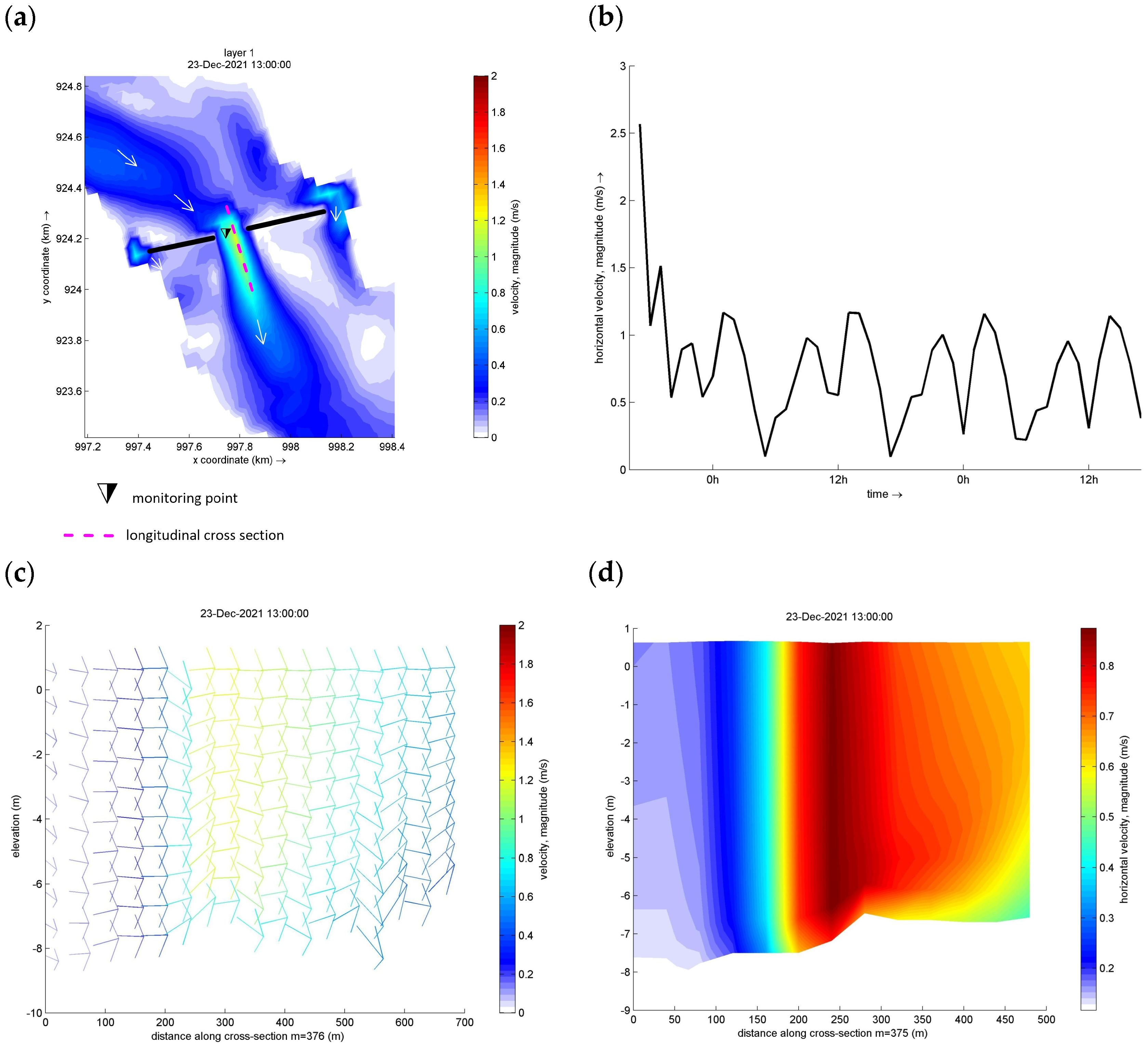
The results of the 3D hydrodynamic model evidence that the numerical scheme (finite difference method) is not appropriate for considering local fluid structure interactions i.e., the flow across hydraulic structures (barrages) (Figure 4). The 24 chambers had a total area of 600 m2 (Figure 2); hence, we set a similar cross-sectional area in the middle of the two dikes of the hydrodynamic model. Although the Delft3D model did not have the same geometry as the CFD model, it was able to simulate the flow contraction at the tidal barrage. The five numerical runs showed that a water jet was generated with velocities that did not exceed 3 m/s (Figure 4).
Additionally, a 2D HEC-RAS model was implemented (www.hec.usace.army.mil/software/hec-ras/, accessed on 10 September 2023), and the results do not reflect the expected behavior of the flow passing though hydraulic structures like gates, mainly because the 2D model integrates along vertical and cannot capture the proper vertical 3D current profiles at the chambers. In this sense, the flow patterns and velocity magnitudes across the gates of the tidal barrage modeled by HECRAS do not properly represent the energy balance nor the intensification of the flow across the gates due to the reduction of the surface control area because of the barrage. However, the results obtained in the HECRAS model show the proper 2D behavior of the velocities in the field plan and the water jet generated by the contraction of the flow at the gates.
Considering the limitations found in the results of the Delft3D and HECRAS models, to simulate the fluid–structure interaction between the chambers and the marine currents, it was decided to address the restriction through CFD modeling. Therefore, the CFD model used the results of the Deflt3D model as the initial and boundary conditions to simulate the local hydraulics of the tidal barrage plant. In the following section, the CFD results for different tidal conditions are presented.

3.2. Computational Fluid Dynamic (CFD) Modeling

The hydraulic modeling of the tidal barrage was performed in 0D and 3D using the theoretical equation for validation (Equation (2)) and the CFD model, respectively. Two tidal conditions were considered to calculate the flow and velocities across the full open gate of 5 × 5 m of the cross-sectional area in the submerged condition (e.g., Figure 3), using Equation (1) and the charts of Alberston and Swamee.
The first tidal condition representing Syzygy tides was y 1 = 8.5 m, y 3 = 5 m, a = 5 m, which generated a total hydraulic head of H = 3.5 m. As a security factor, the H was set 0.3 m below the maximum range during Syzygy, R s = 2 M 2 + S 2 = 3.812. The R s was calculated using the amplitude of the harmonics reported in Rueda-Bayona et al. [3]. The second tidal condition representing Stoa was y 1 = 8.5 m, y 3 = 5 m, a = 5 m, which provoked a total hydraulic head of H = 0.5 m, which is a critical water level difference and a low flow discharge. According to the charts, the discharge coefficients for conditions 1 and 2 were 0.5 and 0.18, respectively. As a result, for condition 1, Q = 103.58 m3 and V = 4.14 m/s, and for condition 2, Q = 37.29 m3 and V = 1.49 m/s.
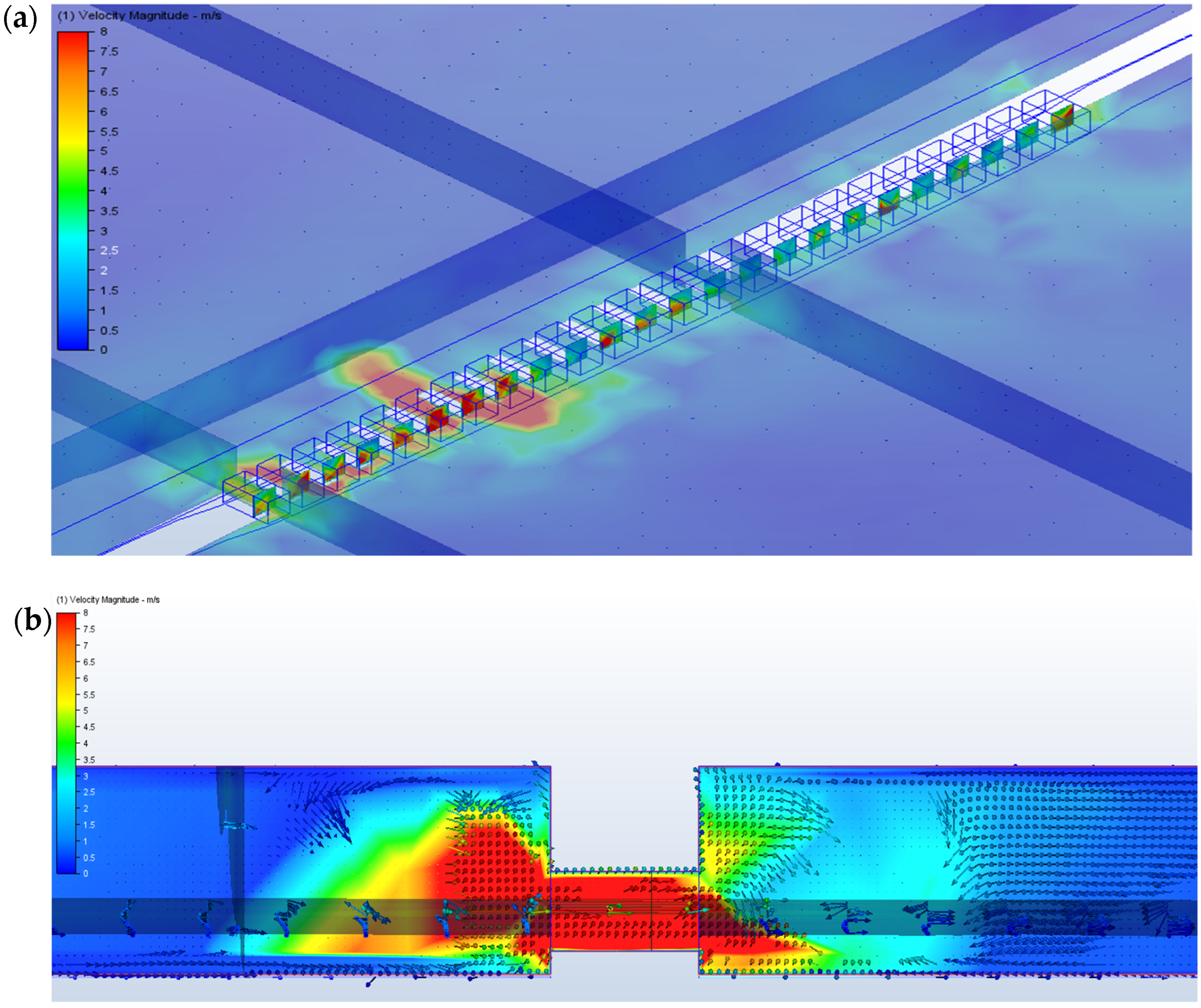
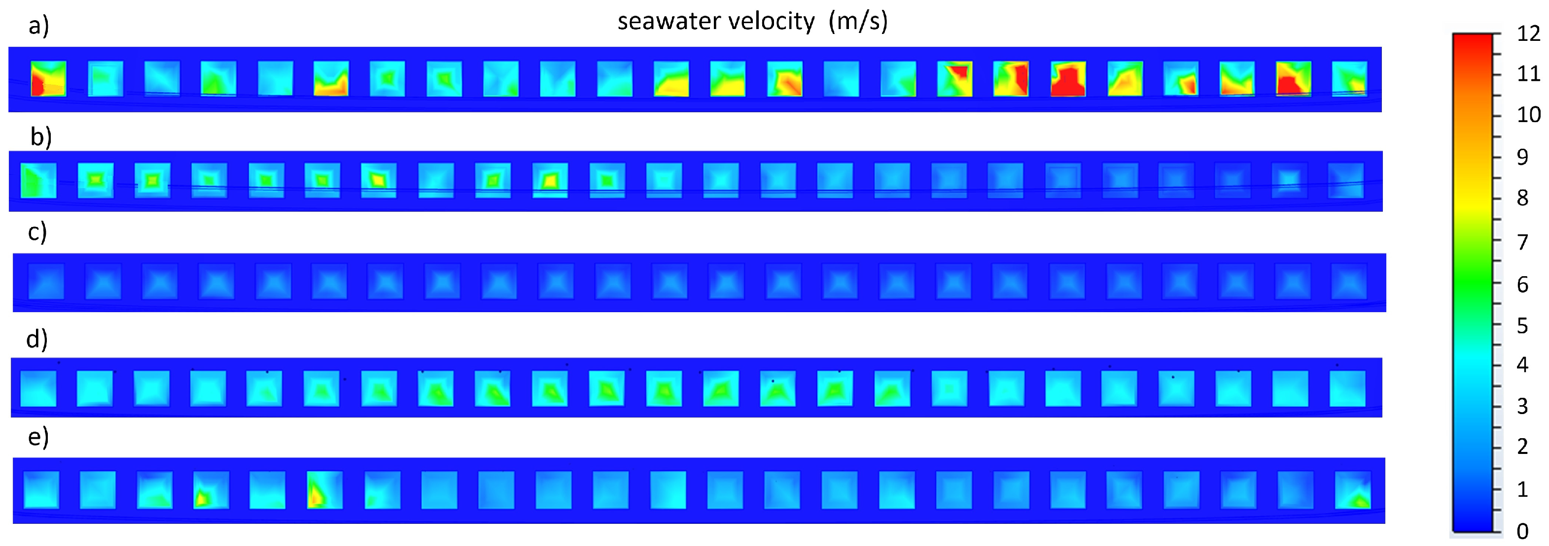
The results of the CFD model show the distribution of the instantaneous velocities along the chambers of the tidal barrage (Figure 5 and Figure 6), where the highest velocities of about 8 m/s occurred in the left section of the barrage. This irregular distribution of the velocities along the barrage was due to the irregular bottom topography of the site. The bathymetry of this research was utilized without modification from the measured data, and the irregular surface generated this non-homogeneous distribution.
The CDF model reported the expected values of currents flowing under gates (Table 2 and Table 3), according to the aforementioned 0D calculations. During the ebb tide in Syzygy the maximum velocities occurred in 21 gates of the tidal barrage, where the highest velocity and flow were 11 m/s and 200 m3/s, registered at gate 18, and the minimums were observed at gates 8–10, with 4.3 m/s and 86 m3/s, respectively. The mean values of velocity and flow during this modeling case were 6.16 m/s and 124.41 m3/s, respectively.
The Stoa modeling case showed the critical condition for power generation, where the velocities did not exceed 1.7 m/s in the 21 chambers of the tidal barrage, and the flow was not higher than 34 m3/s. The mean values of velocity and flow during this modeling case were 0.82 m/s and 30.75 m3/s, respectively. According to the velocity and flow CFD results, they were close to the estimated values for Syzygy and Stoa according to the 0D formula, Equation (1).

4. Discussion

According to the preliminary results, the velocities of Syzygy (April 2021), showed high velocities between 9 and 11 m/s, which suggests a high possibility of producing electricity through tidal turbines. The mean behavior of the velocities in the gates had values of 3 and 5 m/s in most of the cases. The results of the Stoa were very interesting because it was not expected to have flow velocities more than 1 m/s. These are promising results because they indicate that the plant might produce electricity even during the Stoa condition.
To estimate the generated power, the theorical 0D equations of Angeloudis et al. [36] were used to validate the generated power of the tidal barrage using the CFD results of flow and velocity. The results of the hydraulic parameters are listed in Table 4. The calculated generated power using the CFD results indicate that Syzygy provoked the highest energy production, and Stoa, despite being a critical event, allowed for the possibility of producing electricity (Table 5).
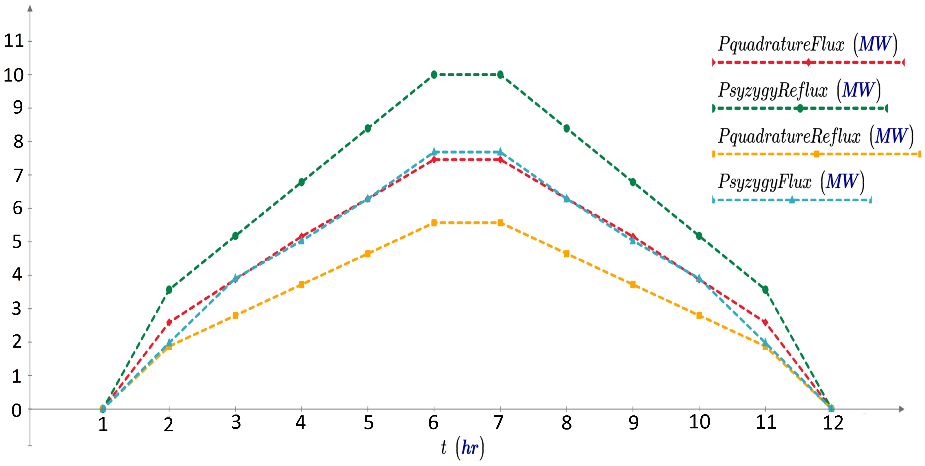
The individual mean power curve shows the evolution of power generation within the semidiurnal tidal cycle of Buenaventura Bay (Figure 7). The production peak occurred during the transition between the ebb and flood tides, when the maximum flow velocity and flow discharge occurred, and the lowest power production was during the Stoa events. Table 6 summarizes the results of the power generation for each tidal event, where the maximum and minimum power production are listed.
After the calculation of the generated power, it was necessary to identify a proper turbine for the tidal barrage. Herrera [37] recommends using Kaplan turbines when the hydraulic head is smaller than 10 m with a high flow (>10 m3/s), matching the results of this study (Table 5). The versatility of Kaplan turbines facilitates their application in Buenaventura Bay because they can adapt the blades and overall orientation for several flow rates, achieving power generation higher than 30 MW for hydraulic heads between 1 and 3 m. Kaplan turbines have a working operational range between 2 m3/s and 500 m3/s; hence, they can work in variable flow discharge generated by the tidal cycle, like in Buenaventura. The tidal plants of Sihwa (South Korea) and La Rance (France) operate with bulb turbines, which require constant control through gates for a uniform discharge. Therefore, Kaplan turbines might operate better in tidal barrage plants without sluicing or gate control.
A pre-feasibility analysis is valuable to compare the generated power results against other tidal plants in operation. Table 7 lists the main characteristics of five plants now operating in the world [38] and the results of the future tidal plant of Buenaventura. The first tidal plant was in La Rance, France, and it was started in 1966 to produce 600 million kWh every year, covering 45% of energy demand of the Brittany region. This plant works with 24 bulb turbines, with a runner diameter of 5.35 m, double-regulated, 10 MW, and 93.75 rev/min [39]. The most recent and largest tidal plant is in Sihwa, South Korea. It was built in 2011 and generates 260 MWh using dikes with a length of 12.5 km and 10 bulb turbines with a maximum hydraulic head of 9.8 m.
The comparison of the main results of this study against the main characteristics of other tidal plants now operating (Table 7) suggest that a future tidal plant in Buenaventura Bay might produce 130.8 MW of electricity, reaching the third highest total installed capacity worldwide, after the Sihwa and La Rance tidal plants. The semidiurnal tidal cycle and the tidal range of Buenaventura, with a low basin area, compared to the abovementioned tidal plants makes Buenaventura an interesting place to develop further studies and increases the feasibility of the construction of the first tidal plant in Colombia. Additionally, Buenaventura bay has a tidal range of about 3.5 m. Its semidiurnal tidal cycle and the basin area revealed that the flow across the chambers of the tidal barrage may produce electricity over 100 MW. It is important to consider that this study performed CFD simulations with rectangular geometry and without sluicing (gate controlling) to allow for free flow within the basin. As a result, it was demonstrated that it is possible to generate a significant amount of energy without water retention, which could generate changes in the water quality at the basin.

5. Conclusions and Recommendations

This research implemented a 3D hydrodynamic model (Delft3D) and a CFD model (Autodesk) to study the hydraulics of a future tidal barrage plant without sluicing in Buenaventura Bay. The Delft3D model allowed for simulating the flows and velocities in the study area, and the results were utilized as inputs for the initial conditions of the CFD model. The main tidal events of Syzygy, Stoa, and Quadrature of 2021 were selected. The Delft3D results indicate that the ebb tide of Syzygy generated the highest flow and velocities, the ebb tide of Quadrature had the lowest records, and Stoa was the critical condition for energy production.
The CFD results were validated with the parameterized 0D equations, considering the flow and velocities of each tidal event. The total generated power calculated for the three tidal events revealed that during the ebb tide of the highest Syzygy, 240 MW was generated. The minimum power generation occurred in the ebb tide of the lowest Quadrature (89 MW), and during Stoa, the total power was 19.7 MW, which is a promising result because, during this critical time, no generation was expected, but electricity production occurred.
We recommend further research related to water quality modeling in Buenaventura Bay, because there are no such studies reported. These studies should consider not only the natural dynamics, but also the effect of placing barrages, dykes, and gates in the study area. Also, it is important to consider the effects of the nearby river discharges and the effects of the runoff and rain over the basin area to understand how the fresh water affects the energy potential.
Further CFD modeling is required considering the fluid–structure interaction of diverse configurations of turbines e.g., bulb, Kaplan, rim, Savonius, and stream turbines, among others. We suggest taking as a reference the used turbines in La Rance, because their runner diameter and flow could be appropriate for the Buenaventura oceanographic and hydrographic conditions. It is important to define which operation mode (pumping, sluicing, ebb–flood generation, etc.) of the tidal barrage plant would be appropriate for Buenaventura Bay, not only in terms of power, but also considering the dynamics of the water quality and the risk of injuring native species. It is very important to evaluate eco-friendly and resistant materials for building the tidal barrage and manufacturing the hydraulic components of the system because the corrosion and degradation of the materials could increase the OPEX (operational expenditure) of the future project.
The results of this study widen the knowledge of the feasibility of a tidal range plant in Colombia and provide better insight into the potential of generating electricity using tidal barrages without gates sluicing. Herein, the achieved results demonstrate that there is potential for producing electricity in Buenaventura Bay, like the currently operating tidal plants. This potential could be increased with further studies considering sluicing, hydraulic optimization with Venturi chambers, and other available estuaries within the bay. Finally, the results of this research revealed, for the first time, the opportunity for generating electricity by means of a tidal barrage plant without sluicing in Buenaventura Bay.

Author Contributions

Conceptualization, J.G.R.-B. and D.P.; methodology, J.G.R.-B. and D.P.; validation, J.G.R.-B. and D.P.; investigation J.G.R.-B. and D.P.; resources, J.G.R.-B.; writing—original draft preparation, J.G.R.-B. and D.P.; writing—review and editing, J.G.R.-B. and D.P.; supervision, J.G.R.-B.; project administration, J.G.R.-B.; funding acquisition, J.G.R.-B. All authors have read and agreed to the published version of the manuscript.

Funding

This research was funded by Universidad del Valle and through the research project 1214.

Data Availability Statement

The measured oceanographic data were provided by the General Maritime Directorate (DIMAR, in Spanish) of Colombia.

Conflicts of Interest

The authors declare no conflicts of interest.

References

  1. Rueda-Bayona, J.G.; Guzmán, A.; Eras, J.J.C.; Silva-Casarín, R.; Bastidas-Arteaga, E.; Horrillo-Caraballo, J. Renewables Energies in Colombia and the Opportunity for the Offshore Wind Technology. J. Clean. Prod. 2019, 220, 529–543. [Google Scholar] [CrossRef]
  2. Gato, L.M.C.; Henriques, J.C.C.; Carrelhas, A.A.D. Sea Trial Results of the Biradial and Wells Turbines at Mutriku Wave Power Plant. Energy Convers. Manag. 2022, 268, 115936. [Google Scholar] [CrossRef]
  3. Rueda-Bayona, J.G.; Vélez, J.L.G.; Parrado-Vallejo, D.M. Effect of Sea Level Rise and Access Channel Deepening on Future Tidal Power Plants in Buenaventura Colombia. Infrastructures 2023, 8, 51. [Google Scholar] [CrossRef]
  4. Quintero, G.; Rueda-Bayona, J.G. Tidal Energy Potential in the Center Zone of the Colombian Pacific Coast. INGECUC 2021, 17, 65–75. [Google Scholar] [CrossRef]
  5. International Renewable Energy Agency. Innovation Outlook Ocean Energy Technologies A Contribution to the Small Island Developing States Lighthouses Initiative 2.0 about IRENA; International Renewable Energy Agency: Abu Dhabi, United Arab Emirates, 2020. [Google Scholar]
  6. Bae, Y.H.; Kim, K.O.; Choi, B.H. Lake Sihwa Tidal Power Plant Project. Ocean. Eng. 2010, 37, 454–463. [Google Scholar] [CrossRef]
  7. Kidd, I.M.; Fischer, A.; Chai, S.; Davis, J.A. A Scenario-Based Approach to Evaluating Potential Environmental Impacts Following a Tidal Barrage Installation. Ocean Coast. Manag. 2015, 116, 9–19. [Google Scholar] [CrossRef]
  8. Hooper, T.; Austen, M. Tidal Barrages in the UK: Ecological and Social Impacts, Potential Mitigation, and Tools to Support Barrage Planning. Renew. Sustain. Energy Rev. 2013, 23, 289–298. [Google Scholar] [CrossRef]
  9. Petley, S.; Starr, D.; Parish, L.; Underwood, Z.; Aggidis, G.A. Opportunities for Tidal Range Projects beyond Energy Generation: Using Mersey Barrage as a Case Study. Front. Archit. Res. 2019, 8, 620–633. [Google Scholar] [CrossRef]
  10. Prime, T.; Wolf, J.; Lyddon, C.; Plater, A.; Brown, J.; Prime, T.; Wolf, J.; Lyddon, C.; Plater, A.; Brown, J. The Potential of Tidal Barrages and Lagoons to Manage Future Coastal Flood Risk. EGUGA 2017, 19, 18785. [Google Scholar]
  11. Severn Tidal Power-Sea Topic Paper Hydraulics and Geomorphology; Parsons Brinckerhoff Ltd.: Bristol, UK, 2010.
  12. Environmental Issues, Dams and Fish Migration|Request PDF. Available online: https://www.researchgate.net/publication/27335307_Environmental_issues_dams_and_fish_migration (accessed on 15 September 2023).
  13. Severn Tidal Power: Noise and Vibration Topic Report for the Strategic Environmental Assessment (SEA)—GOV.UK. Available online: https://www.gov.uk/government/publications/45-severn-tidal-power-noise-and-vibration-topic-report-for-the-strategic-environmental-assessment-sea (accessed on 15 September 2023).
  14. Frau, J.P. Tidal Energy: Promising Projects La Rance, a Succesful Industrial-Scale Experiment. IEEE Trans. Energy Convers. 1993, 8, 552–558. [Google Scholar] [CrossRef]
  15. Underwood, G.J.C. Microphytobenthos and Phytoplankton in the Severn Estuary, UK: Present Situation and Possible Consequences of a Tidal Energy Barrage. Mar. Pollut. Bull. 2010, 61, 83–91. [Google Scholar] [CrossRef] [PubMed]
  16. Burrows, R.; Walkington, I.; Yates, N.; Hedges, T.; Chen, D.; Li, M.; Zhou, J.; Wolf, J.; Proctor, R.; Holt, J.; et al. Tapping the Tidal Power Potential of the Eastern Irish Sea Final Report; University of Liverpool and Proudman Oceanographic Laboratory: Liverpool, UK, 2006. [Google Scholar]
  17. Pethick, J.S.; Morris, R.K.A.; Evans, D.H. Nature Conservation Implications of a Severn Tidal Barrage—A Preliminary Assessment of Geomorphological Change. J. Nat. Conserv. 2009, 17, 183–198. [Google Scholar] [CrossRef]
  18. Langston, W.J.; Pope, N.D.; Jonas, P.J.C.; Nikitic, C.; Field, M.D.R.; Dowell, B.; Shillabeer, N.; Swarbrick, R.H.; Brown, A.R. Contaminants in Fine Sediments and Their Consequences for Biota of the Severn Estuary. Mar. Pollut. Bull. 2010, 61, 68–82. [Google Scholar] [CrossRef] [PubMed]
  19. Neill, S.P.; Angeloudis, A.; Robins, P.E.; Walkington, I.; Ward, S.L.; Masters, I.; Lewis, M.J.; Piano, M.; Avdis, A.; Piggott, M.D.; et al. Tidal Range Energy Resource and Optimization—Past Perspectives and Future Challenges. Renew. Energy 2018, 127, 763–778. [Google Scholar] [CrossRef]
  20. Yates, N.; Walkington, I.; Burrows, R.; Wolf, J. Appraising the Extractable Tidal Energy Resource of the UK’s Western Coastal Waters. Philos. Trans. R. Soc. A Math. Phys. Eng. Sci. 2013, 371, 20120181. [Google Scholar] [CrossRef] [PubMed]
  21. Adcock, T.A.A.; Draper, S.; Nishino, T. Tidal Power Generation—A Review of Hydrodynamic Modelling. Proc. Inst. Mech. Eng. Part A J. Power Energy 2015, 229, 755–771. [Google Scholar] [CrossRef]
  22. Burrows, R.; Yates, N.C.; Hedges, T.S.; Li, M.; Zhou, J.G.; Chen, D.Y.; Walkington, I.A.; Wolf, J.; Holt, J.; Proctor, R. Tidal Energy Potential in UK Waters. Proc. Inst. Civ. Eng.-Marit. Eng. 2015, 162, 155–164. [Google Scholar] [CrossRef]
  23. Burrows, R.; Walkington, I.A.; Yates, N.C.; Hedges, T.S.; Wolf, J.; Holt, J. The Tidal Range Energy Potential of the West Coast of the United Kingdom. Appl. Ocean. Res. 2009, 31, 229–238. [Google Scholar] [CrossRef]
  24. Angeloudis, A.; Piggott, M.; Kramer, S.C.; Avdis, A.; Coles, D.; Christou, M. Comparison of 0-D, 1-D and 2-D Model Capabilities for Tidal Range Energy Resource Assessments; OSF: Charlottesville, VA, USA, 2017. [Google Scholar] [CrossRef]
  25. Cornett, A.; Cousineau, J.; Nistor, I. Assessment of Hydrodynamic Impacts from Tidal Power Lagoons in the Bay of Fundy. Int. J. Mar. Energy 2013, 1, 33–54. [Google Scholar] [CrossRef]
  26. Bray, S.; Ahmadian, R.; Falconer, R.A. Impact of Representation of Hydraulic Structures in Modelling a Severn Barrage. Comput. Geosci. 2016, 89, 96–106. [Google Scholar] [CrossRef]
  27. Zhou, J.; Pan, S.; Falconer, R.A. Effects of Open Boundary Location on the Far-Field Hydrodynamics of a Severn Barrage. Ocean Model. 2014, 73, 19–29. [Google Scholar] [CrossRef]
  28. Rueda-Bayona, J.G.; Paez, N.; Eras, J.J.C.; Gutiérrez, A.S. DOE-ANOVA to Optimize Hydrokinetic Turbines for Low Velocity Conditions. Math. Model. Eng. Probl. 2022, 9, 979–988. [Google Scholar] [CrossRef]
  29. Jeffcoate, P.; Stansby, P.; Apsley, D. Flow and Bed-Shear Magnification Downstream of a Barrage with Swirl Generated in Ducts by Stators and Rotors. J. Hydraul. Eng. 2016, 143, 06016023. [Google Scholar] [CrossRef]
  30. Oh, S.H.; Lee, K.S.; Jeong, W.M. Three-Dimensional Experiment and Numerical Simulation of the Discharge Performance of Sluice Passageway for Tidal Power Plant. Renew. Energy 2016, 92, 462–473. [Google Scholar] [CrossRef]
  31. Deltares. Delft3D-FLOW: Simulation of Multi-Dimensional Hydrodynamic Flows and Transport Phenomena, Including Sediments—User Manual; Deltares: Delft, The Netherlands, 2014. [Google Scholar]
  32. Angeloudis, A.; Kramer, S.C.; Hawkins, N.; Piggott, M.D. On the Potential of Linked-Basin Tidal Power Plants: An Operational and Coastal Modelling Assessment. Renew. Energy 2020, 155, 876–888. [Google Scholar] [CrossRef]
  33. Swamee, P.K. Sluice-Gate Discharge Equations. J. Irrig. Drain. Eng. 1992, 118, 56–60. [Google Scholar] [CrossRef]
  34. Albertson, M.L.; Dai, Y.B.; Jensen, R.A.; Rouse, H. Diffusion of Submerged Jets. Trans. Am. Soc. Civ. Eng. 1950, 115, 639–664. [Google Scholar] [CrossRef]
  35. Oskuyi, N.; Salmasi, N. Vertical Sluice Gate Discharge Coefficient. J. Civ. Eng. Urban. 2012, 2, 108–114. [Google Scholar]
  36. Angeloudis, A.; Kramer, S.C.; Avdis, A.; Piggott, M.D. Optimising Tidal Range Power Plant Operation. Appl. Energy 2018, 212, 680–690. [Google Scholar] [CrossRef]
  37. Herrera, P. Diseño Y Simulacion de Una Turbina Kaplan Mediante Dinamica de Fluidos Computacional; University of Cantabria: Cantabria, Spain, 2021. [Google Scholar]
  38. Shetty, C.; Priyam, A. A Review on Tidal Energy Technologies. Mater. Today Proc. 2022, 56, 2774–2779. [Google Scholar] [CrossRef]
  39. Hammons, T.J. Tidal Power. Proc. IEEE 1993, 81, 419–433. [Google Scholar] [CrossRef]
Figure 1. Study area, location of tidal barrage, monitoring points, and domain of the 3D hydrodynamic model. Coordinates in Magna Sirgas Colombia West unit system. The tidal station and ADCP measurements have the coordinates of 77.08079 W/3.891239 N and 77.146 W/3.837 N, respectively.
Infrastructures 09 00127 g001
Figure 2. Geometry and domain of the configured CFD model representing the tidal barrage: (a) bottom surface; green arrow is the direction of the incoming flow at the boundary, and red and blue arrows are the horizontal x and z coordinate axes, respectively. (b) Water volume (blue) and barrage (green).
Infrastructures 09 00127 g002
Figure 3. Scheme of gate opening under submerged flow conditions.
Infrastructures 09 00127 g003
Figure 4. Three-dimensional hydrodynamic modeling of the tidal barrage area obtained in Delft3D: (a) surface layer velocity, (b) horizontal velocity of the monitoring point, (c) vector velocities, and (d) magnitude velocity in the longitudinal cross section. The arrows represent the vectors of the currents.
Infrastructures 09 00127 g004
Figure 5. CFD velocity results along the barrage during the ebb tide of the highest Syzygy of 2021: (a) top view of the surface layer; (b) longitudinal-sectional view.
Infrastructures 09 00127 g005
Figure 6. Cross-sectional view of CFD velocity results along the barrage during the ebb tide of the highest Syzygy of 2021: (a) highest Syzygy—ebb tide; (b) highest Syzygy—flood tide; (c) Stoa; (d) lowest Quadrature—ebb tide; (e) lowest Quadrature—flood tide.
Infrastructures 09 00127 g006
Figure 7. Individual mean power curve of the tidal barrage for each turbine during Syzygy and Quadrature.
Infrastructures 09 00127 g007
Table 1. CFD numerical cases considering the tidal cycle of the study area.
CaseFlow—North Boundary (m3/s)Flow—South Boundary (m3/s)Velocity—North Boundary (m/s)Flow—South Boundary (m/s)
Lowest Quadrature (22 December 2021, 14:00 h)Flood tide5306500.140.48
Ebb tide5657200.150.16
Highest Syzygy (29 April 2021, 00:00 h)Flood tide7689360.160.54
Ebb tide79710150.440.18
Stoa (22 December 2021, 17:00 h)851070.040.02
Table 2. CFD results of fluid velocities across the gates of the tidal power plant during the most important tidal events of 2021.
Velocity (m/s)
Gate 123456789101112131415161718192021222324
Lowest QuadratureFlood tide4.04.04.06.05.55.55.55.66.06.06.05.85.75.44.04.04.04.04.03.53.23.23.23.2
Ebb tide4.44.14.04.03.63.82.62.72.72.62.62.73.23.03.43.53.63.83.63.83.83.83.93.9
Stoa 1.31.31.41.61.71.71.71.71.71.71.71.71.71.71.71.71.51.51.41.31.31.31.31.3
Highest SyzygyFlood tide5.56.06.05.55.55.56.55.55.56.56.56.56.54.54.54.54.54.03.22.22.22.23.23.2
Ebb tide7.56.54.25.54.56.56.54.34.34.36.86.87.24.34.36.58.211.07.07.56.86.87.54.5
Table 3. CFD results of fluid flow across the gates of the tidal power plant during the most important tidal events of 2021.
Flow (m3/s)
Gate 123456789101112131415161718192021222324
Lowest QuadratureFlood tide80808012011011011011212012012011611410880808080807064646464
Ebb tide888280807276525454525254646068707276727676767878
Stoa 262628323434343434343434343434343030282626262626
Highest SyzygyFlood tide1101201201101101101301101101301301301309090909080644444446464
Ebb tide1501308411090130130868686136136144868613016422014015013613615090
Table 4. Theoretical 0D generated power using the mean CFD velocity values of the 3 extreme representative tidal events i.e., ebb tide of Syzygy, Stoa, and ebb tide of Quadrature. Hydraulic parameters were calculated using Table 2 of Angeloudis et al. [36].
ParameterDescriptionSyzygyStoaQuadrature
H = H Hydraulic head (m)3.50.52.21
S p Turbine speed (rpm)33.994.5519.09
n 11 Unit speed (rpm)90.8432.1664.20
Q 11 Unit discharge (m3/s)2.031.041.58
Q Discharge estimate (m3/s)95.1418.3358.77
P Subjected power to turbine capacity (MW)13.920.385.43
Q h Corrected discharge with maximum capacity (m3/s)396.4276.36244.89
η h Empirical efficiency1.071.181.12
P h Calculated power without efficiency losses (MW)13.920.385.43
Table 5. Theoretical generated power for each gate of the tidal barrage using flows retrieved from the CFD simulations.
Power (MW)
Gate 123456789101112131415161718192021222324
Lowest QuadratureFlood tide4.34.34.36.45.95.95.96.06.46.46.46.26.15.84.34.34.34.34.33.83.43.43.43.4
Ebb tide4.74.44.34.33.94.12.82.92.92.82.82.93.43.23.63.83.94.13.94.14.14.14.24.2
Stoa 0.70.70.80.90.90.90.90.90.90.90.90.90.90.90.90.90.80.80.80.70.70.70.70.7
Highest SyzygyFlood tide8.89.69.68.88.88.810.48.88.810.510.510.510.57.27.27.27.26.45.13.53.53.55.15.1
Ebb tide12.110.56.88.87.210.510.56.96.96.910.910.911.66.96.910.513.217.711.312.110.910.912.17.2
Table 6. Mean generated power of the tidal barrage using the CFD results in Table 5.
Tidal ConditionIndividual Mean Power (MW)Total Power (MW)
Lowest QuadratureFlood tide5.0119.2
Ebb tide3.789.0
Stoa 0.819.7
Highest SyzygyFlood tide7.7185.9
Ebb tide10.0240.0
Mean5.4130.7
Table 7. Comparison of the future tidal barrage plant of Buenaventura against five operating plants worldwide.
ParameterBuenaventura (Future)La RanceSihwaJiangxiaAnnapolisKislaya Guba
Tidal range (m)3.7119.85.16.42.3
Turbine number242410611
Turbine typePreliminarily Kaplan or BulbBulbBulbBulbRimSavonius
Generated power by 1 turbine (MW)5.4510263.9201.7
Total installed capacity (MW)130.824026023.4201.7
Basin area (Km2)7.322561.4151.1
Mean tidal range (m)3.5 8.55.65.16.42.3
Disclaimer/Publisher’s Note: The statements, opinions and data contained in all publications are solely those of the individual author(s) and contributor(s) and not of MDPI and/or the editor(s). MDPI and/or the editor(s) disclaim responsibility for any injury to people or property resulting from any ideas, methods, instructions or products referred to in the content.