
Lessons Learned from the Construction and Initial Performance of a Double Chip Seal over a Paving Mat Pilot Project


Abstract
:1. Introduction
2. Project Information
3. Construction
3.1. Construction Materials
3.1.1. Aggregate
3.1.2. AR (Type II) Binder
3.1.3. Asphalt Emulsions
3.1.4. Paving Mat and Paving Fabric
3.1.5. Asphalt Binder
3.2. General Construction Process
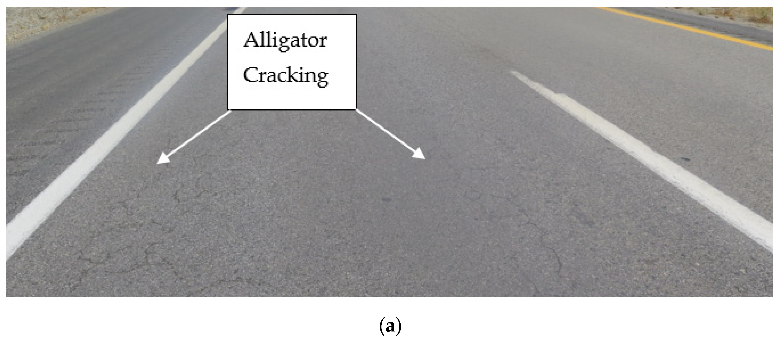
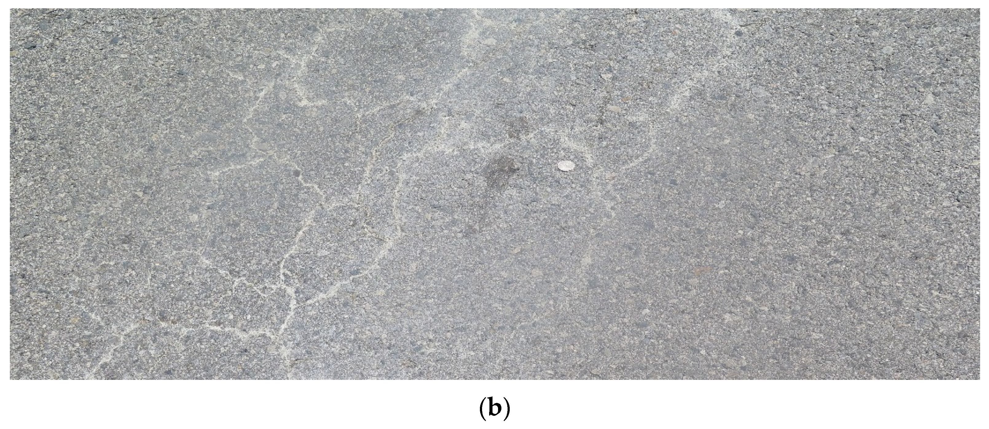
- For each treatment, the pavement markers were removed, and the pavement was swept. No crack sealing was applied on the existing pavement because most of the surface distress was alligator cracking, which was too small for crack sealant application.
- For the paving mat or fabric, the PG 70-10 binder was applied using a BearCat distributor truck also equipped with a bracket for unrolling the GlasPave 50 or PRF directly onto the pavement. The fabric or mat application process was performed simultaneously with the binder application, as shown in Figure 3. Within 10 s after the application, two rubber-tired rollers started working to remove the bubbles and smooth any wrinkles prior to applying the chip seals.
- The first layer of binder (hot AR binder or PME) was applied with predetermined application rates using a hooded distributor truck for the AR binder to control air pollution.
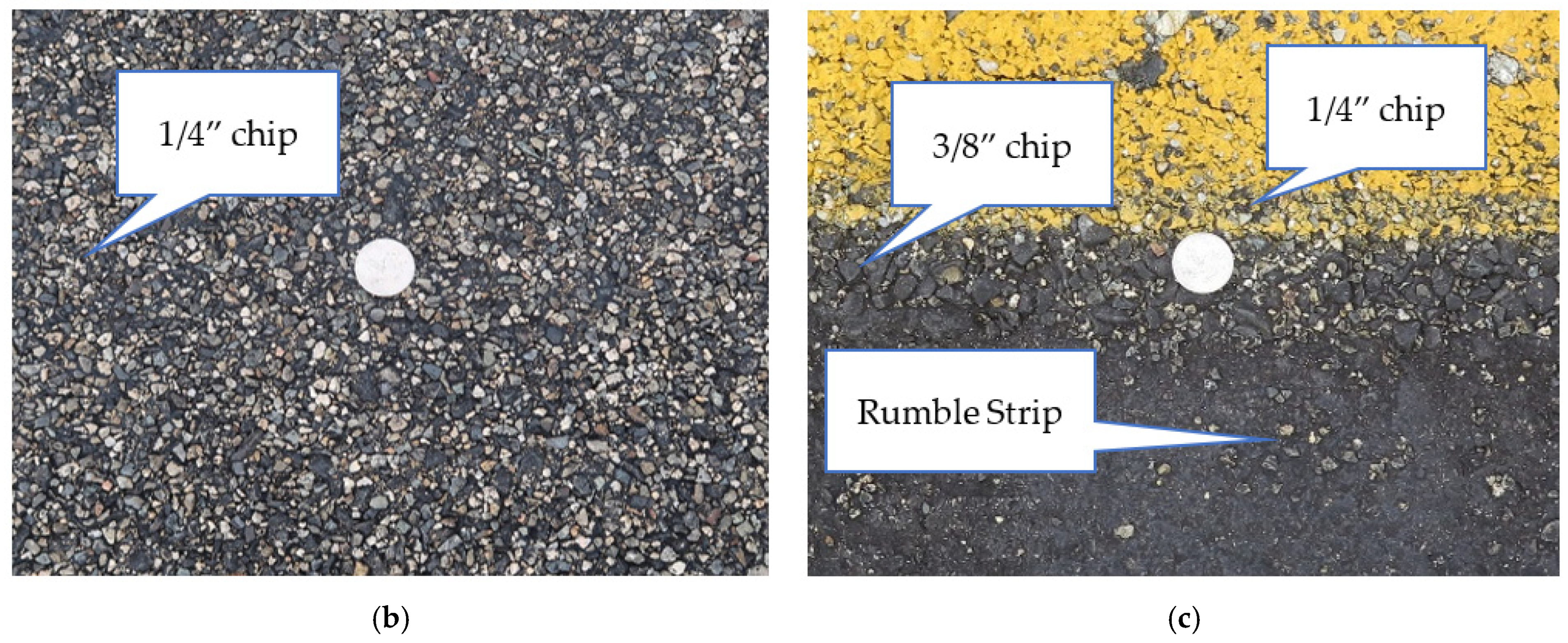
- The 3/8-inch aggregate application (pre-coated hot chips for AR binder or uncoated chips for PME) was carried out using a BearCat chip spreader, with various aggregate dump trucks supplying the material. The aggregate application followed closely behind the binder distributor truck.
- The roller followed very closely after chip application. The minimum number of passes was achieved using two rubber-tired Caterpillar rollers. The fresh chip seal coats were repeatedly rolled and swept after the AR (Type II) binder had cooled and the PME binder was well set.
- The repeated rolling of these binders was performed to compact and to embed the chips into the binders.
- Sweeping was performed approximately three times using a series of two to four self-contained sweepers. Sweeping was performed to remove the loose chips and to decrease the chances of windshield breakage once the road was opened to uncontrolled traffic.
- The second layer of binder (PME) was applied with predetermined application rates. The distribution trucks, without hoods, applied the PME, with aggregate application following closely behind the distribution truck.
- The finer 1/4-inch aggregate application was carried out using the same BearCat chip spreader and various dump trucks.
- The rolling followed very closely after 1/4-inch chip application. Again, the minimum number of passes was achieved using two rubber-tired Caterpillar rollers.
- Sweeping was performed again multiple times to remove the loose chips prior to applying a flush seal.
- A flush coat was applied without sand over the 1/4-inch chip seal. Temporary striping was applied to the new chip seal prior to opening the lanes to uncontrolled traffic.
3.3. Construction Observations and Lessons
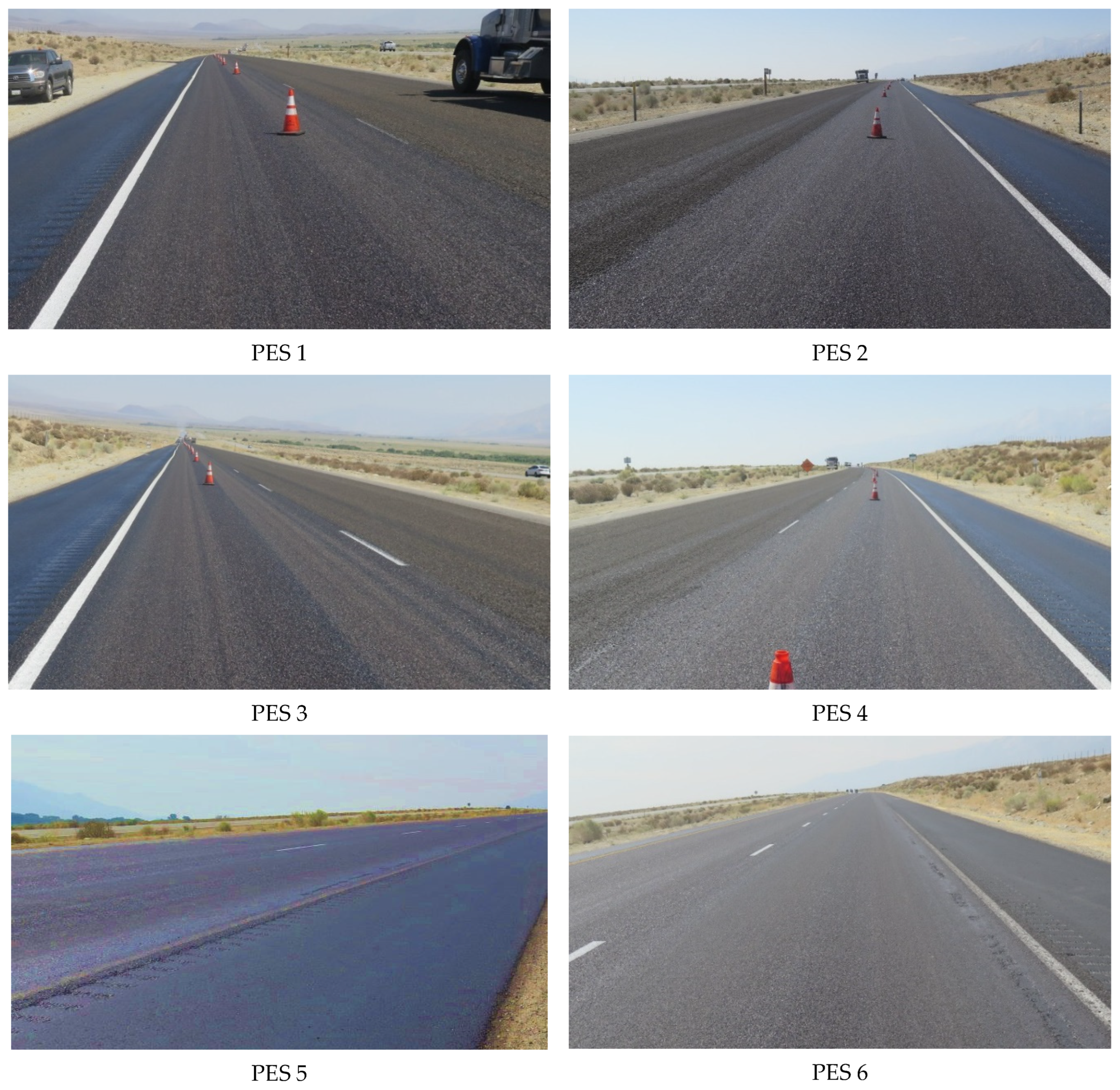
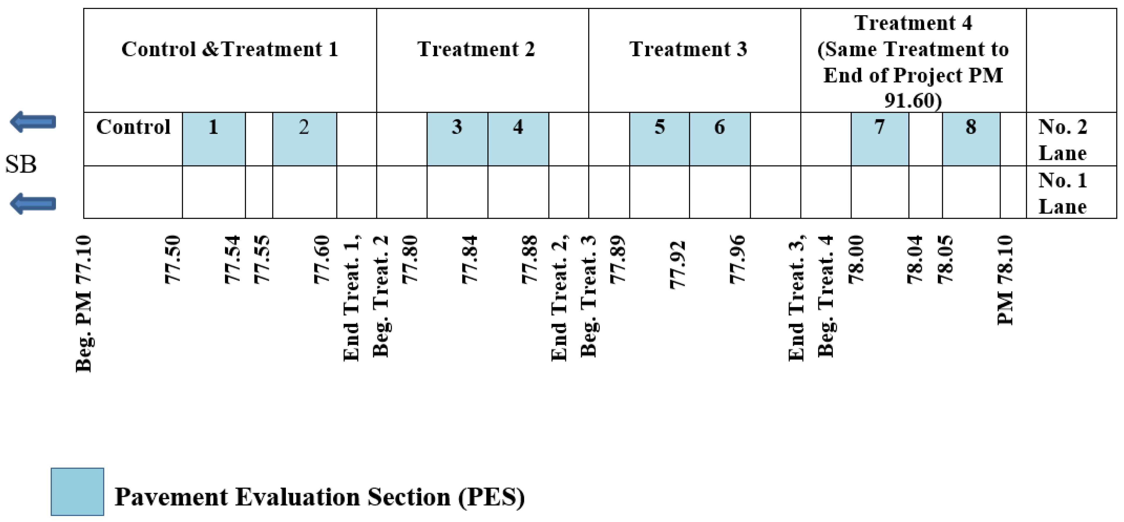
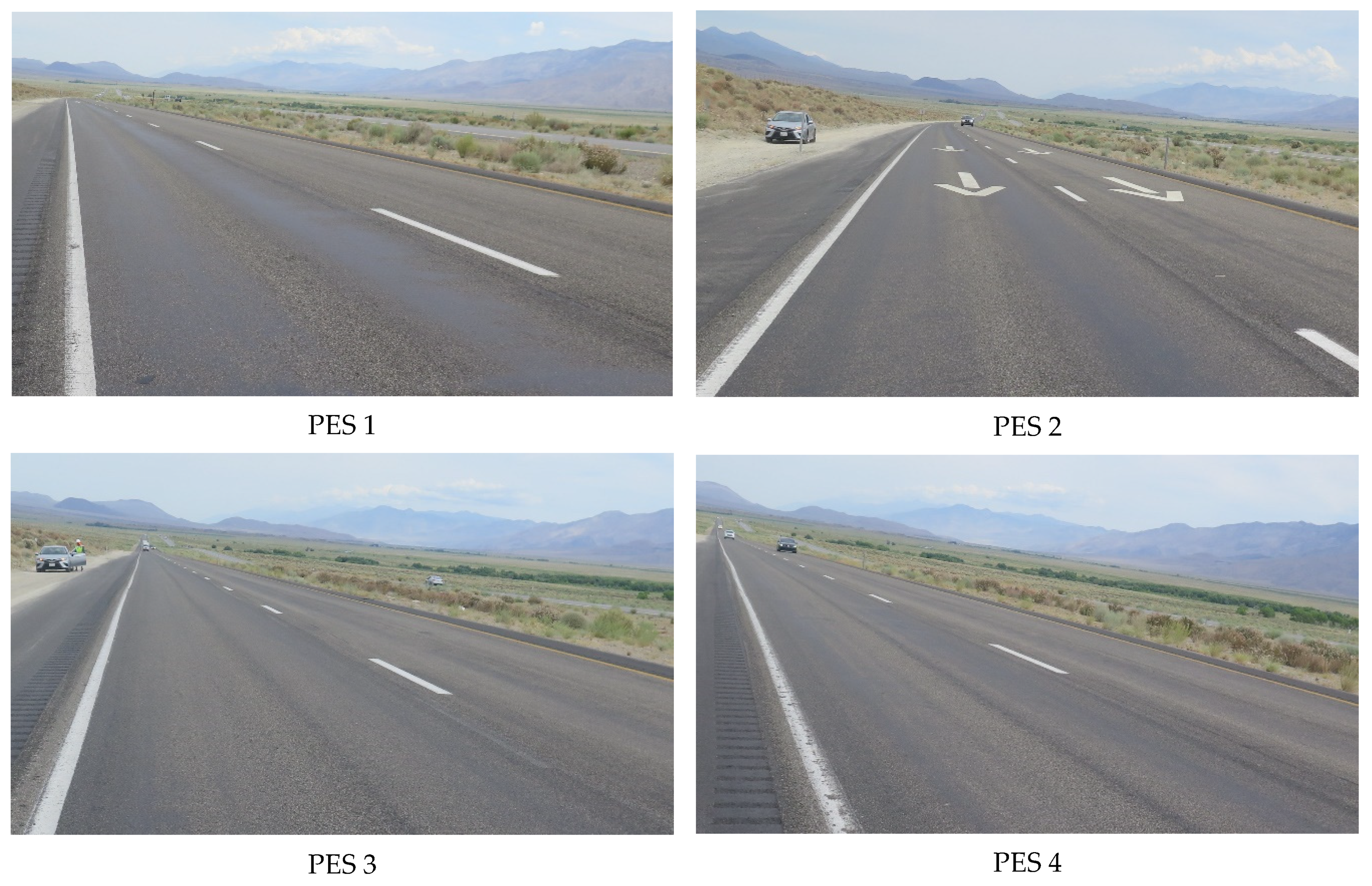
- Treatment 1 includes PES 1 and PES 2. This treatment included an AR (Type II) binder with a 3/8-inch chip seal followed by a PME binder with a ¼-inch chip. The 1/4-inch chip seal was followed by a flush coat of CQS-1H. Treatment 1 did not include either PRF or GlasPave 50.
- Treatment 2 included PES 3 and PES 4. This treatment, over PRF, included a PME binder with a 3/8-inch chip seal followed by a PME binder with a 1/4-inch chip seal. The 1/4-inch chip seal was followed by a flush coat of CQS-1H. The PRF was applied simultaneously with the PG 70-10 binder over the existing pavement.
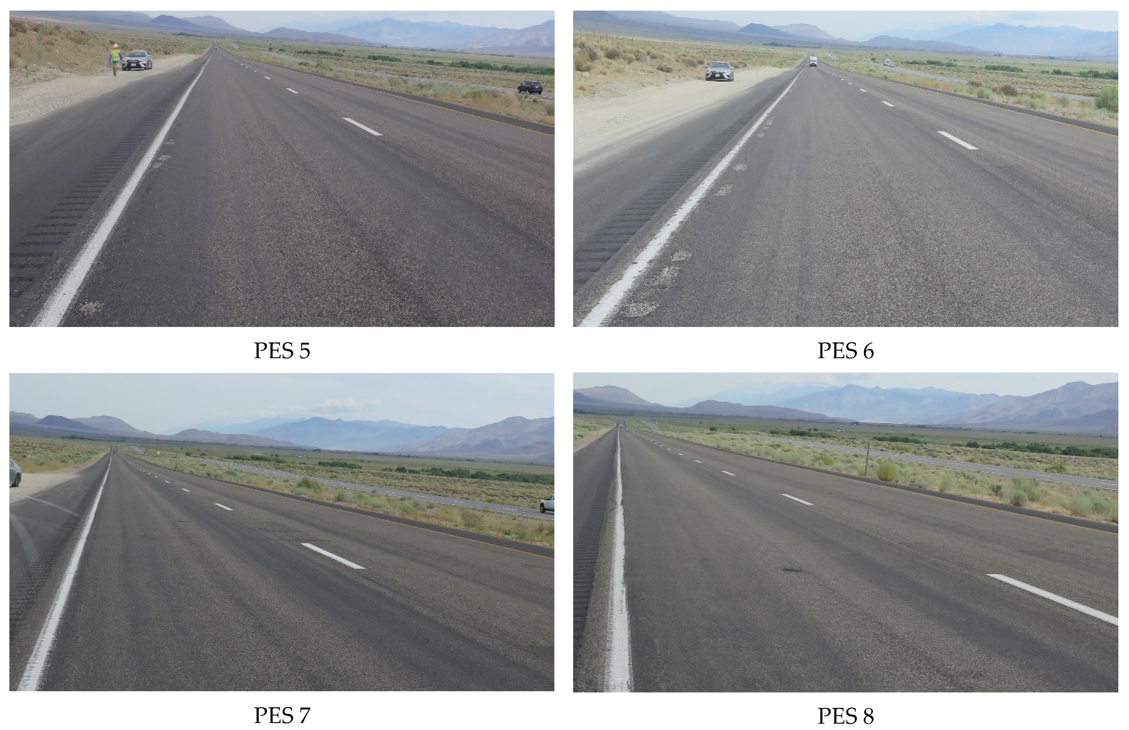
- Treatment 3 included PES 5 and PES 6. This treatment, over GlasPave 50, included a PME binder with a 3/8-inch chip seal followed by a PME binder with a 1/4-inch chip seal. The 1/4-inch chip seal was followed by a flush coat of CQS-1H. The GlasPave 50 was applied simultaneously with the PG 70-10 binder over the existing pavement.
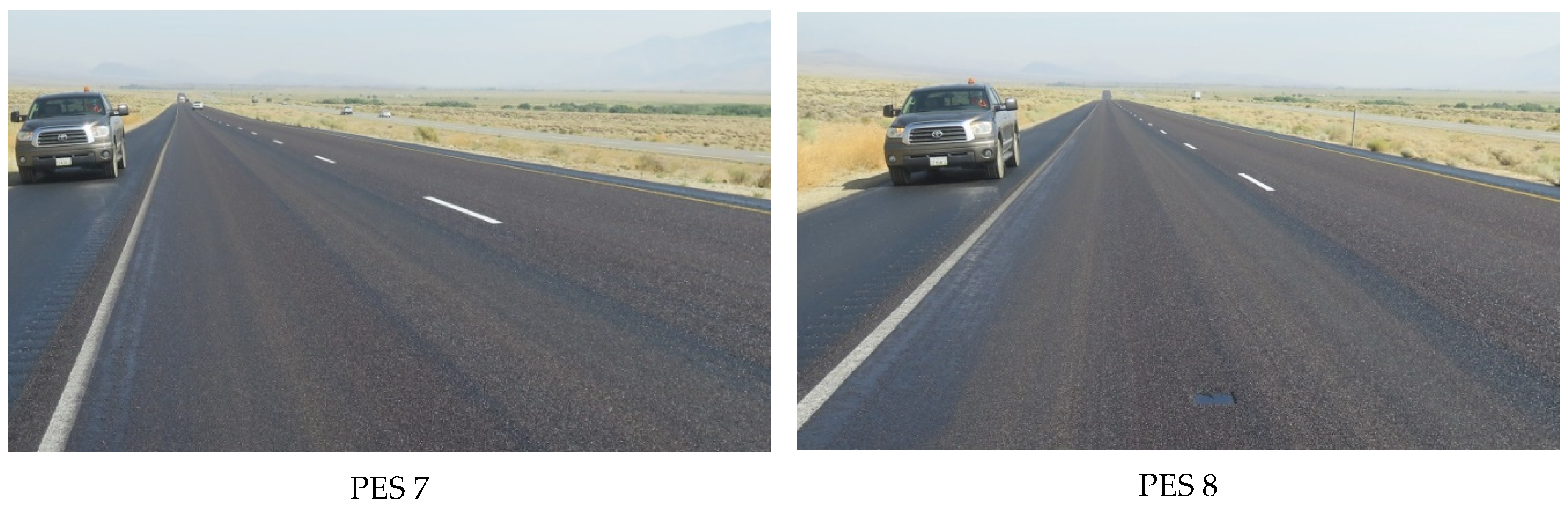
- Treatment 4 included PES 7 and PES 8. This treatment, over GlasPave 50, included an AR (Type II) binder with a 3/8-inch chip seal followed by a PME binder with a 1/4-inch chip seal. The 1/4-inch chip seal was followed by a flush coat of CQS-1H. The GlasPave 50 was applied simultaneously with the PG 70-10 binder over the existing pavement.
3.4. Field Vialit Test Results
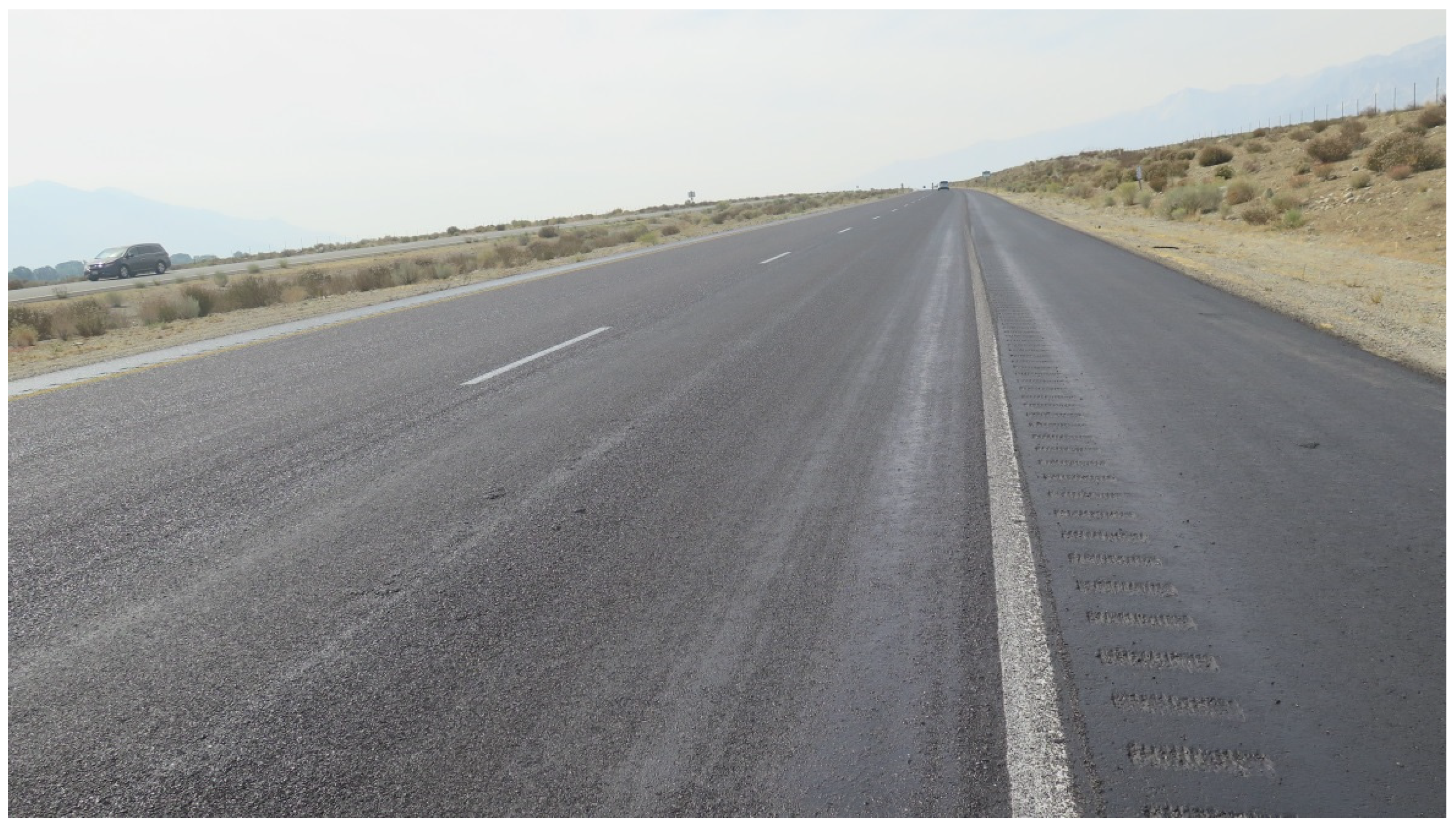
4. Finished Product
5. Initial Field Performance
6. Summary Findings, Lessons Learned, and Recommendations
6.1. Summary
- The pre-existing pavement appeared to have relatively uniform distress and major alligator cracking throughout the southbound No. 2 lane of the project, and where the PESs were constructed.
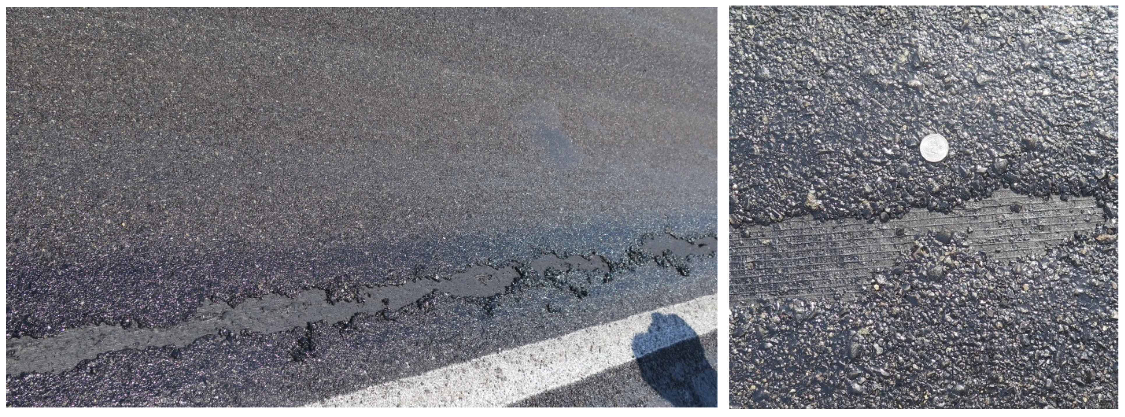
- PESs 5 and 6 had delamination near the edge stripe when the ambient temperature was 105 °F the following day with traffic shifted from the No. 1 Lane to the No. 2 (PES) Lane.
- The contractor placed the GlasPave 50 simultaneously with the PG 70-10 binder, followed immediately by two rubber-tired rollers, which was promptly followed by asphalt rubber binder application with hot pre-coated 3/8-inch aggregate for the chip seal. This application was immediately followed by a train of two rollers to achieve aggregate embedment into the freshly applied binder. The loose chips were then swept into two self-contained sweepers. The construction process seemed efficient.
- The field Vialit test results showed that all double chip seals had a chip retention rate of more than 95%. Based on the one-year performance review, rock loss was not observed and was not a problem for the double chip seal project.
- Based on the pavement performance one year after construction, no alligator cracking was shown in the pilot project. Therefore, double chip seal with and without a paving mat successfully prevented reflective cracking for one year.
- More pilot projects should be constructed in different regions, such as mountain regions as well as valley regions of California, to verify performance.
6.2. Lessons Learned
- Moving high-volume traffic to the fresh PME chip seal with high ambient temperatures and high pavement surface temperatures caused moderate bleeding and delamination over the GlasPave 50 fabric.
- The asphalt rubber binder appeared to adhere better to the paving mat, GlasPave 50. No delamination occurred with the asphalt rubber binder.
- The PME binder adhered better to the PRF than it adhered to the GlasPave 50. No delamination occurred with the PME binder placed over the PRF; however, it bled with traffic running on it one day after placement with high pavement temperatures.
- The double chip seal treatment applied directly to the HMA had heavier bleeding than the double chip seal over the paving mat or the PRF. The paving mat and the PRF appeared to help absorb some excess binder.
- The contractor should have a water truck available to water-cool PME chip seal sections when there is hot weather and the PME is showing distress from low viscosity due to high temperatures.
6.3. Recommendations
- This pilot project’s performance reviews should continue to verify the long-term performance of the various strategies. The pilot chip seal should continue to be monitored at regular intervals over a 7-year period to determine the long-term performance of the four strategies. Crack mapping should be repeated within PESs as well as other forms of distress.
- Life expectancy should be quantified for the four chip seal strategies from future distress data.
- Caltrans should lower the binder application rates or practice construction in cooler weather to prevent the observed bleeding of the double chip seals with or without a paving mat or PRF.
- A future pilot project may use an existing double chip seal as a Stress-Absorbing Membrane Interlayer (SAMI) for an HMA paving project. This could eliminate Caltrans’ standard practice of removing chip seal prior to re-paving.
- A new Caltrans Standard Specification, or Caltrans Standard Special Provision, should be developed for a particular double chip seal treatment based on minimizing long-term pavement distress. A particular treatment strategy could be confirmed from the four treatment strategies used in this pilot project.
Author Contributions
Funding
Data Availability Statement
Acknowledgments
Conflicts of Interest
References
- FHWA. Information: Guidance on Highway Preservation and Maintenance; FHWA, Associate Administrator for Infra-Structure: Washington, DC, USA, 2016. Available online: https://www.fhwa.dot.gov/preservation/memos/160225.cfm (accessed on 31 July 2019).
- AGC, Pavement Preservation Committee. Arizona Chapter. In Chip Seal Guide for Application and Construction, 1st ed.; AGC: Phoenix, AZ, USA, 2013. [Google Scholar]
- Austroads. Austroads Sprayed Sealing Guide; AP-676/104; Austroads: Sydney, Australia, 2004; 104p. [Google Scholar]
- Hanson, F.M. Bituminous Surface Treatments on Rural Highways; Proceedings of the New Zealand Society of Civil Engineers; The National Academies of Sciences, Engineering, and Medicine: Washington, DC, USA, 1934; Volume 21. [Google Scholar]
- Gransberg, D.; James, D.M.B. NCHRP Synthesis 342 Chip Seal Best Practices; Transportation Research Board: Washington, DC, USA, 2005; pp. 1–111. [Google Scholar]
- Mahoney, J.P.; Slater, M.; Keifenheim, C.; Uhlmeyer, J.; Willoughby, K.; Moomaw, T. WSDOT Chip Seals—Optimal Timing, Design, and Construction Considerations; Washington State Transportation Center: Olympia, WA, USA, 2014; pp. 1–88. [Google Scholar]
- Peshkin, D.; Smith, K.L.; Wolters, A.; Krstulovich, J.; Moulthrop, J.; Alvarado, C. “Definitions”. In Guidelines for the Preservation of High-Traffic-Volume Roadways, 2nd ed.; National Academy of Sciences: Washington, DC, USA, 2011; pp. 2–3. [Google Scholar]
- Pierce, L.M.; Kebede, N. Chip Seal Performance Measures—Best Practices; Applied Pavement Technology, Inc.: Urbana, IL, USA, 2015; pp. 1–57. [Google Scholar]
- ISSA. Recommended Performance Guideline for Chip Seal; ISSA A 165; International Slurry Surfacing Association: Annapolis, MD, USA, 2012. [Google Scholar]
- Testa, D.M.; Hossain, M. Kansas Department of Transportation 2014 Chip Seal Manual; Department of Transportation, Bureau of Materials & Research: Topeka, KS, USA, 2014.
- Martin, A.E.; Arámbula-Mercado, E.; Theeda, S.M.; Chang, S.; Epps, J.; Freeman, T.J. Statewide Implementation of the Surface Performance Graded (SPG) Specification for Chip Seal Binders in Service: Implementation Report; Texas A&M Transportation Institute: Bryan, TX, USA; Texas Department of Transportation: Austin, TX, USA; Federal Highway Administration: Washington, DC, USA, 2022.
- Chang, S.; Zhang, L.; Li, S.; Gharaibeh, N.; Martin, A.E.; Hazlett, D. Evaluation of the causal effect of the surface performance-graded (SPG) specification for chip seal binders on performance. Constr. Build. Mater. 2021, 304, 124518. [Google Scholar] [CrossRef]
- Haider, S.W.; Boz, I.; Kumbargeri, Y.; Kutay, E.; Musunuru, G. Development of performance related specifications for chip seal treatments. Int. J. Pavement Eng. 2021, 22, 382–391. [Google Scholar] [CrossRef]
- Mousa, M.R.; Elseifi, M.A.; Bashar, M.Z.; Zhang, Z.; Gaspard, K. Short and Long-Term Field Performances and Optimal Timing of Chip Seal in Hot and Humid Climates. Transp. Res. Rec. 2020, 2674, 33–43. [Google Scholar] [CrossRef]
- California Department of Transportation (Caltrans). Maintenance Technical Advisory Guide—Volume I Flexible Pavement Preservation, 2nd ed.; California Department of Transportation: Sacramento, CA, USA, 2008.
- Elseifi, M.A.; Rahman, M.N.; Sarkar, M.T.; Abohamer, H. Evaluation of Asphalt Rubber and Reclaimed Tire Rubber in Chip Seal Applications; Louisiana State University: Baton Rouge, LA, USA; Louisiana Department of Transportation and Development: Baton Rouge, LA, USA; Federal Highway Administration: Washington, DC, USA, 2022.
- Kumbargeri, Y.; Boz, I.; Kutay, M.E. Comparative Investigation of Hot-Applied and Emulsion-Based Chip Seal Treatments Using Image Processing Techniques and Performance Tests. J. Transp. Eng. Part B Pavements 2021, 147, 04021039. [Google Scholar] [CrossRef]
- Rahman, M.N.; Sarkar, M.T.A.; Elseifi, M.A.; Mayeux, C.; Cooper, S.B.; Free, K. Short-Term Field Performance and Cost-Effectiveness of Crumb-Rubber Modified Asphalt Emulsion in Chip Seal Applications. Transp. Res. Rec. J. Transp. Res. Board 2021, 2675, 1049–1062. [Google Scholar] [CrossRef]
- Hicks, R.G.; Cheng, D.; Lane, L. Manual for Chip Seals; Mineta Transportation Institute: San Jose, CA, USA; San Jose State University: San Jose, CA, USA, 2019. [Google Scholar]
- California Department of Transportation (Caltrans). Asphalt Rubber Usage Guide; California Department of Transportation: Sacramento, CA, USA, 2008.
- California Department of Transportation (Caltrans). 2013 Annual Average Daily Truck Traffic on the California State Highway System; California Department of Transportation: Sacramento, CA, USA, 2013.
- California Department of Transportation (Caltrans). Automated Pavement Condition Survey Manual; California Department of Transportation: Sacramento, CA, USA, 2015.
- Caltrans, Specifications for Bituminous Seals (Hot and Cold Applied), Section 37; California Department of Transportation: Sacramento, CA, USA, 2015.
- Fraser, B.; Cheng, D. Vialet Testing Results for Rubber Modified Seal Coat Project on CA SR 36, CP2C-2014-105; California Pavement Preservation Center: Chico, CA, USA, 4 May 2014. [Google Scholar]
- AASHTO. Standard Practice for Emulsified Asphalt Chip Seal Design; American Association of State Highway Transportation Officials (AASHTO): Washington, DC, USA, 2016; pp. 82–86. [Google Scholar]
- Shuler, S.; Lord, A.; Epps-Martin, A.; Hoyt, D. Manual for Emulsion-Based Chip Seals for Pavement Preservation; NCHRP Report 680; Transportation Research Board of the National Academies: Washington, DC, USA, 2011. [Google Scholar]


| Distress | PES 1 | PES 2 | PES 3 | PES 4 | PES 5 | PES 6 | PES 7 | PES 8 | Total |
|---|---|---|---|---|---|---|---|---|---|
| Alligator B Cracking Low-to-Medium Severity, Linear feet, Left Wheel Path | 200 | 200 | 200 | 120 | 200 | 200 | 200 | 200 | 1520 |
| Alligator B Cracking Low-to-Medium Severity, Linear feet, Right Wheel Path | 200 | 120 | 200 | 200 | 200 | 200 | 200 | 200 | 1520 |
| Right and Left Wheel Paths Total linear feet | 400 | 320 | 400 | 320 | 400 | 400 | 400 | 400 | 1340 |
| Pumping (ft2) | 0 | 0 | 0 | 0 | 112 | 198 | 472 | 636 | 1418 |
| Steps | Materials | Treatment 1 (PESs 1, 2) | Treatment 2 (PESs 3, 4) | Treatment 3 (PESs 5, 6) | Treatment 4 (PESs 7, 8) |
|---|---|---|---|---|---|
| 1 | PG 70-10/GlasPave 50 | -- | -- | 0.20 gal/yd2 | 0.20 gal/yd2 |
| 2 | PG 70-10/PRF | -- | 0.35 gal/yd2 | -- | -- |
| 3 | AR (Type II) | 0.6 gal/yd2 | -- | -- | 0.6 gal/yd2 |
| 4 | PMCRS-2H Emulsion | -- | 0.32 gal/yd2 | 0.32 gal/yd2 | -- |
| 5 | 3/8-inch Chips | 32 lbs/yd2 | 25 lbs/yd2 | 25 lbs/yd2 | 32 lbs/yd2 |
| 6 | PMCRS-2H Emulsion | 0.26 gal/yd2 | 0.26 gal/yd2 | 0.26 gal/yd2 | 0.26 gal/yd2 |
| 7 | 1/4-inch Chips | 16 lbs/yd2 | 16 lb/yd2 | 16 lb/yd2 | 16 lb/yd2 |
| 8 | Flush Coat, CQS-1H (50/50) | 0.10 gal/yd2 | 0.10 gal/yd2 | 0.10 gal/yd2 | 0.10 gal/yd2 |
| PES Section | 2 | 4 | 6 | 8 | Retention Specification for Double Chip Seal |
| Sample Description | Double Chip—1/4” Chip with PME over 3/8” Chip with AR | Double Chip—1/4” Chip with PME over 3/8” Chip with PME | Double Chip—1/4” Chip with PME over 3/8” Chip with PME | Double Chip—1/4” Chip with PME over 3/8” Chip with AR | |
| Retention Results (%) | 99 | 98 | 99 | 99 | 95 |
| Distress | PES 1 | PES 2 | PES 3 | PES 4 | PES 5 | PES 6 | PES 7 | PES 8 |
|---|---|---|---|---|---|---|---|---|
| Moderate Bleeding (ft2) | 400 | 400 | 0 | 0 | 0 | 0 | 0 | 0 |
| Light Bleeding (ft2) | 0 | 0 | 400 | 400 | 400 | 400 | 400 | 400 |
| Patching (ft2) | 0 | 0 | 0 | 0 | 26 | 112 | 0 | 0 |
| Raveling (ft2) | 0 | 0 | 0 | 0 | 33 | 0 | 6 | 0 |
| Delamination (ft2) | 0 | 0 | 0 | 0 | 0 | 0 | 0 | 3 |
Disclaimer/Publisher’s Note: The statements, opinions and data contained in all publications are solely those of the individual author(s) and contributor(s) and not of MDPI and/or the editor(s). MDPI and/or the editor(s) disclaim responsibility for any injury to people or property resulting from any ideas, methods, instructions or products referred to in the content. |
© 2023 by the authors. Licensee MDPI, Basel, Switzerland. This article is an open access article distributed under the terms and conditions of the Creative Commons Attribution (CC BY) license (https://creativecommons.org/licenses/by/4.0/).
Share and Cite
Cheng, D.; Lane, L. Lessons Learned from the Construction and Initial Performance of a Double Chip Seal over a Paving Mat Pilot Project. Infrastructures 2023, 8, 134. https://doi.org/10.3390/infrastructures8090134
Cheng D, Lane L. Lessons Learned from the Construction and Initial Performance of a Double Chip Seal over a Paving Mat Pilot Project. Infrastructures. 2023; 8(9):134. https://doi.org/10.3390/infrastructures8090134
Chicago/Turabian StyleCheng, DingXin, and Lerose Lane. 2023. "Lessons Learned from the Construction and Initial Performance of a Double Chip Seal over a Paving Mat Pilot Project" Infrastructures 8, no. 9: 134. https://doi.org/10.3390/infrastructures8090134
APA StyleCheng, D., & Lane, L. (2023). Lessons Learned from the Construction and Initial Performance of a Double Chip Seal over a Paving Mat Pilot Project. Infrastructures, 8(9), 134. https://doi.org/10.3390/infrastructures8090134