Article

Numerical and Experimental Behavior Analysis of Slabs Strengthened Using Steel Plates and Slurry-Infiltrated Mat Concrete (SIMCON) Laminates

by
Ali Sadik Gafer Qanber
1,2,
Mohammed H. Yas
1,* and
Mohammed M. Kadhum
3
1
Faculty of Engineering, Razi University, Kermanshah 67144-14971, Iran
2
Department of Biomedical Engineering, College of Engineering, University Of Babylon, Babylon 51002, Iraq
3
Faculty of Engineering, University of Babylon, Babylon 51002, Iraq
*
Author to whom correspondence should be addressed.
Infrastructures 2023, 8(5), 85; https://doi.org/10.3390/infrastructures8050085
Submission received: 20 February 2023 / Revised: 5 April 2023 / Accepted: 23 April 2023 / Published: 29 April 2023

Abstract

:
This study has two main aims; firstly, investigating the behavior of slabs that are strengthened with different types of reinforcements and with Slurry-Infiltrated Mat Concrete (SIMCON) laminates, having different dimensions and thicknesses and subjected to static and dynamic (impact) loads. Secondly, the development of a non-linear finite element (FE) model to simulate the behavior of the tested slabs utilizing the ABAQUS/Standard package. The modeling of the NSC slabs strengthened with either SIMCON or steel plates involves using three-dimensional solid elements that are partially integrated with the modeling of concretes using the 8-node brick element (C3D8R). The results of the experimental and numerical investigations are compared to examine whether the slab modeling is sufficient. The comparison includes the element type, material characteristics, real constants, and convergence study. The predicted ultimate load-carrying capacity versus vertical deformation response is compared with the lab results that correspond with it, as obtained via the FE analysis of all tested slabs. In addition, the results of the FE analysis of slab specimens that are strengthened with steel plates were compared to the results of the ones strengthened using SIMCON laminates. The obtained results have led to a number of significant observations. Considering the punching shear strength, it was found that using SIMCON strengthening in different dimensions increased the slab’s punching shear capacity and outperformed steel-strengthened slabs. As for the plate stiffness, SIMCON-strengthened slabs presented higher stiffness rates than steel-strengthened slabs, to the extent that even 20 mm SIMCON strengthening outperformed the steel plate-strengthened slabs of any thickness or dimensions. The axial load-displacement relationships indicate that all the numerical models show a stiffer behavior when compared with the experimental axial load-displacement relationships. The slab thickness of SIMCON significantly affects the load-carrying capacity, and it increases with the increase in thickness. Likewise, using strengthening from steel plates gives a higher load-carrying capacity. Finally, since the results of the yield line analyses for these slabs are found to match the experimental results closely, this method is considered to be suitable for practical use in determining the strength of plated slabs. Therefore, the conclusion is drawn that the proposed FE model can be sufficiently used in evaluating the dynamic responses of slabs strengthened with SIMCON or steel plates and subjected to cyclic and impact load.

1. Introduction

Concrete is the main material in the infrastructure that is required to maintain human life on this planet, and it represents the main pile in civilization [1,2]. At the same time, concrete structures, especially reinforced concrete (RC) structures, often require strengthening and repair [3,4]. At the present time, engineers have generally tended to identify the optimal way of enhancing concrete performance using a set of criteria, such as concrete strength, durability, workability, and sufficient service life [5,6,7]. To exemplify, tanks, bridges, pavements, highways and machine foundations, and off-shore structures demand a relatively higher fatigue strength [8,9,10]. To address these aspects, Slurry-Infiltrated Mat Concrete (SIMCON) is introduced as a suitable solution, resulting from material alteration for increasing how stiff, ductile, and strong the members are [11,12,13]. It is a cementitious composition with advanced steel fiber reinforcement. These steel fibers undergo a mechanical preplacement in the form of a mat, which is densely packed into a roll with specific thickness, fiber volume, and fiber dimensions criteria [14]. In SIMCON, the volume fraction, length, and aspect ratios of fiber rise remarkably, which in turn corresponds to an increase in flexural strength and other mechanic properties [15,16].
As compared to Slurry-Infiltrated Fibrous Concrete (SIFCON), the random plane distribution of steel fibers in SIMCON results in better flexural strength. It has been found that SIMCON could behave similarly to SIFCON in terms of flexure but with approximately half the fiber volume fracture [17]. In SIFCON, flexural failure occurs in the form of a main crack; meanwhile, multiple cracks were observed in SIMCON [18,19,20]. Other advantages of SIMCON include providing the same strength and energy absorption capacity as SIFCON at a lower fiber volume [21]. Using SIMCON includes the use of stainless steel in the fiber mats Hackman, Farrell, and Dunham [18], which limits corrosion greatly. The provision of steel fibers as mats makes it easier to place and handle on construction sites [22]. On the other hand, it is found to be stronger whenever the fibers have a perpendicular orientation to the loading axis [23,24].
A number of studies have examined the effect of SIMCON strengthening on the structural behavior of specimens. Krstulovic-Opara [5] created SIMCON models for tension and compression and showed that SIMCON could be potentially used for repairing and retrofitting structures that already exist [25,26]. Balamuralikrishnan and Jeyasehar [27] investigated the flexural strength of reinforced concrete beams both experimentally and analytically using externally bonded SIMCON laminates. The prediction of the theoretical moment-curvature relationship of specimens and the load-displacement response of beams (strengthened and controlled) was performed using the FEA software ANSYS. By comparing the numerically obtained results to the ones obtained experimentally and theoretically, it was concluded that a higher flexural strength and stiffness, as well as composite action until failure, was found for the strengthened beams. Harris [28] tested 12 square Reactive Powder Concrete (RPC) slabs of dimensions (1143 × 1143 mm) to investigate the boundaries between flexural and punching shear failures. The main factor taken into consideration is the slab thickness (50.8, 63.5, and 76.2 mm). The slab support in all cases is found to be on the end that is fully restrained, with a concentric loading. The conclusion was drawn that only small loading areas were needed for forcing punching shear failures in RPC slabs when dealing with small plate tests, taking into account the flexural capacity and deflection criteria.
Steel plates are commonly applied to strengthen reinforced concrete beams and slabs. The plate bonding method has attracted the attention of many researchers over time, as it is considered to be a simple and fast method that results in minimal increases in terms of structural self-weight and size. Elbakry and Allam [29] studied, both experimentally and analytically, the punching shear strength of RC two-way slabs strengthened with steel plates. Better results were obtained for the strengthened slabs in terms of stiffness and punching shear strength, which is mainly determined by the plate dimensions, stud diameter, and arrangements. The increase in punching shear strength after steel strengthening is predicted analytically using the proposed approach. The latter was applied to the test specimens using the punching shear equations adopted in a number of codes of practice. Zhang et al. [30] found that two-way reinforced concrete slabs can be efficiently strengthened using external steel plate bonding. Sim and Oh [31] experimentally demonstrated how using external bonds of steel plates when strengthening RC bridge deck panels under punching load leads to a substantial increase in the load-carrying capacity and flexural stiffness.
Given the fact that certain RC structures require redesigning to resist impact loading, it is important to ensure the predictability of the response and damage that may eventually occur to the RC structures under impact loading. The impact response of reinforced concrete members could be reliably studied using impact tests [24,32,33]. These tests demonstrate how important the inertia forces are. The force-time history values of the aforementioned tests indicate that the slab inertia forces resist the impact force during the initial phase. The forces that are developed at the supports increase in prominence after the impact occurs, leading to the observation of equilibrium at this stage. In addition, it was found that the reaction forces during measurement were about of similar value; meanwhile, the impact forces varied despite being equal in magnitude to mass times acceleration [34,35].
In light of the review conducted, it has been found that there is a lack of research regarding the rehabilitation and strengthening of plate slab specimens or SIMCON laminates subjected to cyclic and impact loadings. The majority of works address the strengthening of slabs that are subjected to static load [14,36,37]. This implies the need for an experimental and theoretical investigation of plate strengthening. Therefore, this work aims to develop different techniques to strengthen NSC slap specimens against punching shear or flexure, once using SIMCON laminates and again using steel plates, which are subjected to cyclic and impact loading. Moreover, a numerical modeling approach is designed to investigate the efficiency of these strengthening techniques in enhancing the behavior of NSC plates subjected to various loads. The experimentally obtained test results represent valuable data that can be used in verifying FE models and which can also be adopted in developing future analytical tools for strengthening concrete slabs under cyclic and impact loads.

2. Experimental Work

The experimental work includes evaluating traditional strengthening techniques using steel plates, as compared to the modern strengthening techniques whereby SIMCON laminates are used to enhance the behavior of NSC plates subjected to various loads. Different variables are taken into consideration in this experiment, including strengthening type, cross-section, and thickness of plates. The experimental procedure adopted for achieving the goals of this study is comprehensively presented in the following sections. It demonstrates the properties of the materials used (cement, natural sand, steel fiber, mineral, and chemical admixtures), mix proportions, casting, compacting, curing of the developed samples, and testing methods.

2.1. Properties of Materials

Among the materials used in this work is ordinary Portland cement (type Ι). The used cement is produced in Iraq by KARASTA and is largely available in the local market. The fine aggregate complies with the limitations stated in the Iraqi standard No. 45/1984 [38].
The silica fume, also known as Mega Add MS (D) from CONMIX, conforms to the ASTM C1240-15 requirements and has been used to replace approximately 10% of the cement for enhancing the microstructure of cement paste, eventually increasing its resistance. The present study uses new, high-strength fibers, which are provided in the form of mats to undergo infiltration. These fiber mats are manufactured by Ganzhou Daye Metallic Fibres Co., Ltd., Ganzhou, China. The main reinforcement bars were deformed steel bars with a unified size of (Ø6 mm nominal diameter). These bars function as flexural reinforcement put within the tension face of NSC plates. Steel wires of (1 mm) were used for the arrangement and connection of reinforcement bars. The used steel bolts have an ultimate tensile strength of (235 kN). The function of these bolts is to ensure that the concrete and steel plates interact fully and that a confinement pressure is applied to the concrete plates after tightening the bolt nuts. The High Range Water Reducing Admixture (HRWRA) adopted in the present work is a 3rd generation super plasticizer (SP) for concrete and mortar. In commerce, it is also referred to as Hyperplast PC200, which is a high-performance SP used in concrete admixtures provided by DCP. It consists of an aqueous solution with modified poly-carboxylic polymers and long chains that are free of chlorides, and it complies with the requirements of ASTM C494/2017 type F. The bonding agent of the epoxy resin used in this experiment is the Concressive® 2200, which MBT’s Dubai, UAE facility supplies. It was chosen for bonding the steel plate and the hardened RC plates. The epoxy features conform to the ASTM C881M-02 type 1, grade 3, and classes B and C.

2.2. Mix Design

Until present, there are no particular criteria or specifications for the SIMCON mixture design. The information provided in this work is merely adopted from other related works. After multiple trials, ordinary Portland cement with a (969) kg/m3 content was utilized in this work before replacing 10% of it with silica fume. As for the water/binder ratio, it remained constant at a value of 0.33 (by weight), whereas the SP ratio was 3.7%. The mix proportions of SIMCON are shown in Figure 1. A total of 6% of the steel fiber was adopted to cast plate specimens. Normal Strength Concrete (NSC) with non-strengthened plates was also used for comparison purposes (control or reference) with other strengthened plates. The maximum size of crushed aggregate in NSC is 9.5 mm, and the NSC mix design conforms to the specifications of the American mixing design methods ACI 211.1-91, which is presented in Figure 1.

2.3. Samples Description

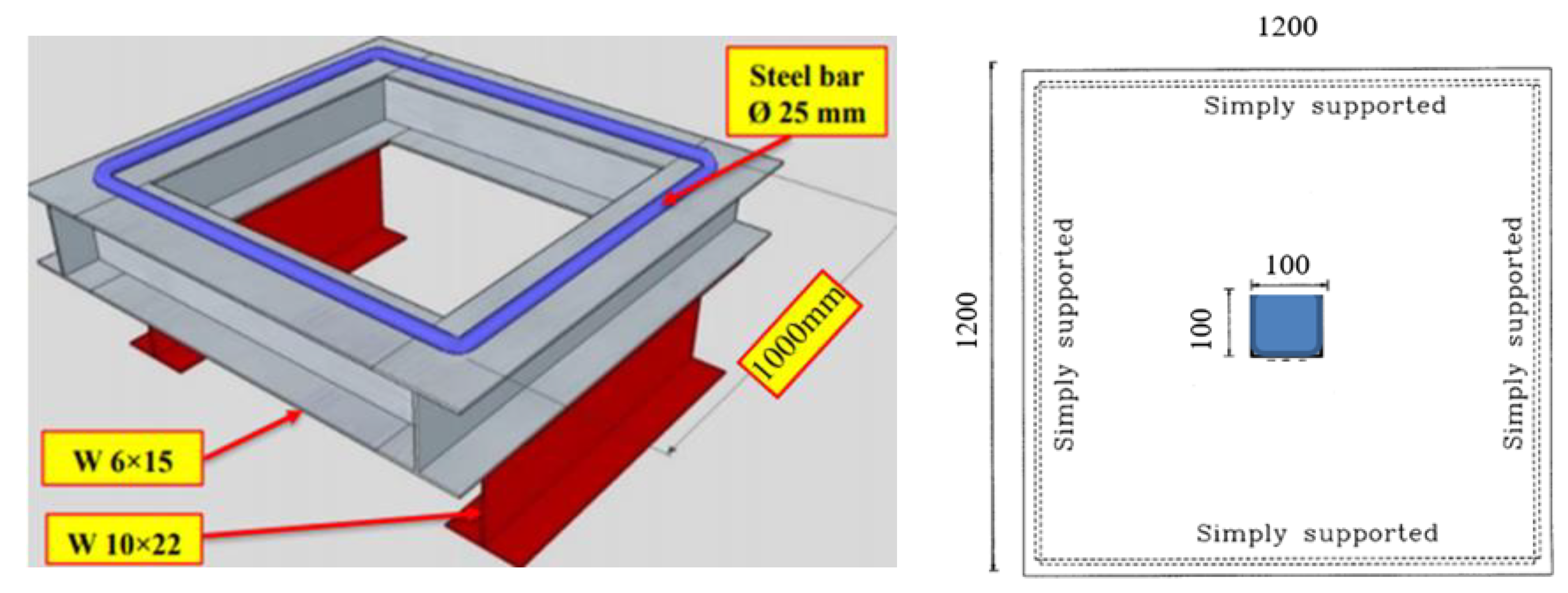
Several different variables are considered in this experiment, including steel plate thickness, plate size, number of bolts, and the SIMCON layer thickness. The slab specimen has a square plan with an overall side length of (1200 mm) and a thickness of (50 mm). The slabs have simple support on each of its four sides, over a span of (1000 mm), and in both directions. The reinforcement used in the slab specimen is a bottom mesh with (6 mm) diameter high tensile steel bars. One size of deformed steel bars was used as the main reinforcing bars with the size of (Ø6 mm nominal diameter) placed as flexural reinforcement in the tension face of NSC plates. All reinforcing bars were arranged and connected together using (1 mm) steel wire. The test results indicate that the average yield strength is equal to (560 MPa). The reinforcement used for the manufacturing of test specimens has yield strength, ultimate strength, and modulus of elasticity values of (fy = 426 Mpa), (fu = 595 Mpa), and (Es = 208 Gpa), respectively. The effective depth of flexural reinforcement in both directions is (18 mm). The rebar spacing in specimens is Ø6mm @75 × 75 mm (for NSC only). The specimen dimensions and reinforcing details are shown in Figure 2.
The test specimens are split into three groups.
Group 1 includes the control samples. This group includes four non-strengthened slab specimens intended to measure either the cyclic or impact load applied onto the slab specimens.
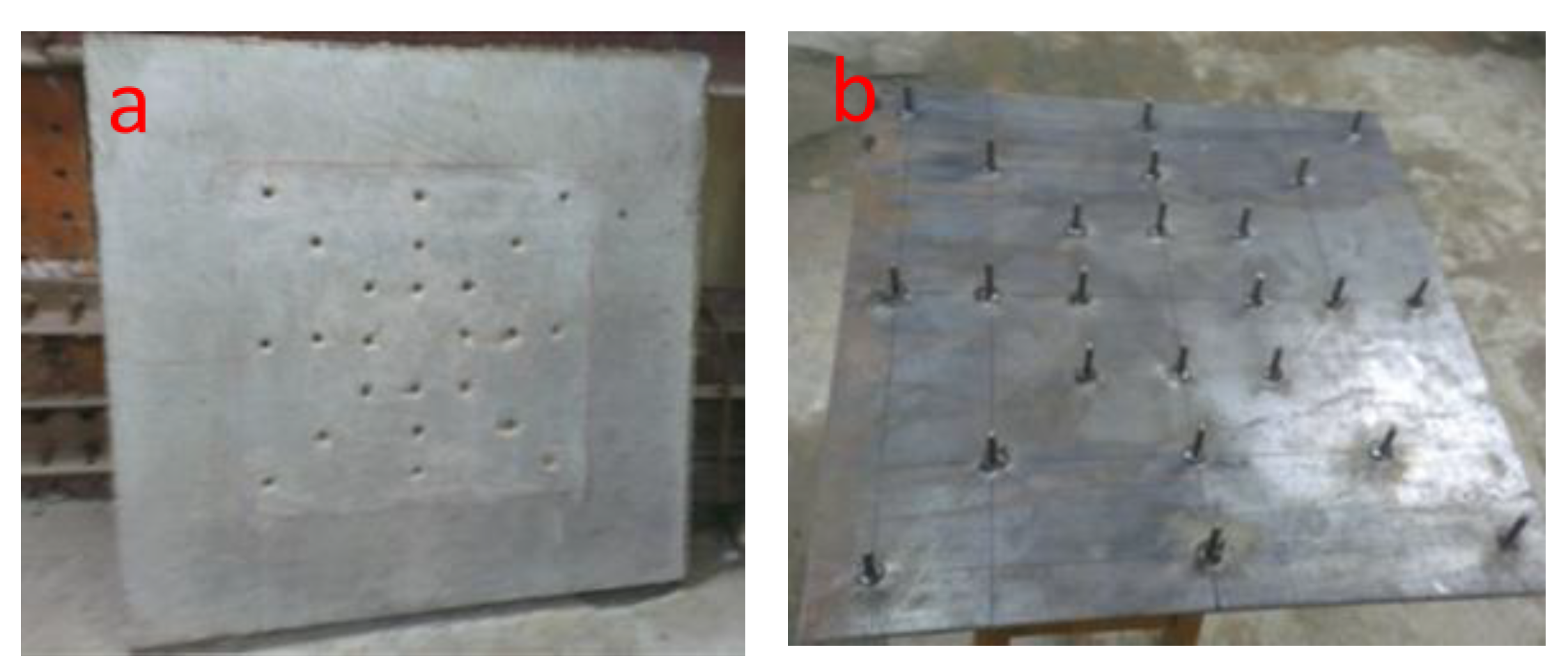
Group 2 includes 12 samples that are strengthened using a steel plate with steel bolts, which are also subjected to either impact or cyclic loads. The steel plates are (500 mm × 500 mm), (750 mm × 750 mm), and (full scale = 1200 mm × 1200 mm) dimensions, having variable thicknesses (2 and 4 mm). These steel plates are externally bonded at the center of the slab tension face, presented in Figure 3, whereby (16, 24, 32) steel shear bolts of 6 mm in diameter and 60 mm length are welded to the steel plate in order of size (from smallest to greatest, respectively). Next, it is embedded into the concrete plate to enhance the composite action of the specimen.
Group 3 involves 12 specimens that are strengthened using SIMCON laminates (hybrid concrete) of (500 mm × 500 mm), (750 mm × 750 mm), and (full scale = 1200 mm × 1200 mm) dimensions with variable thicknesses (20 and 30 mm). They are also subjected to either impact load or cyclic load.
The plates in groups 2 and 3 are adopted to investigate the efficiency of the proposed strengthening techniques. The samples are named according to the type of loading and the way they are strengthened, as explained in Figure 4. Table 1 displays the test specimen parameters.

2.4. Construction Procedure

Before starting the casting process of the slab specimens, the mix volume determines the preparation and weighing of the selected materials. All testing slab specimens are cast in plywood molds and have dimensions of (1200 × 1200 mm) with a height of 50 mm, as presented in Figure 5. The casting procedure can be outlined through the following steps:
  • The forms are oiled prior to placing the reinforcements. The cage is then put into the form with the support of several chairs.
  • All specimens are cast simultaneously to minimize any variation in material properties, as presented in Figure 5.
  • Concrete buckets are used for pouring the mix into the forms, after which they are vibrated. The air bubbles that appear on the surface indicate that the forms are fully compacted.
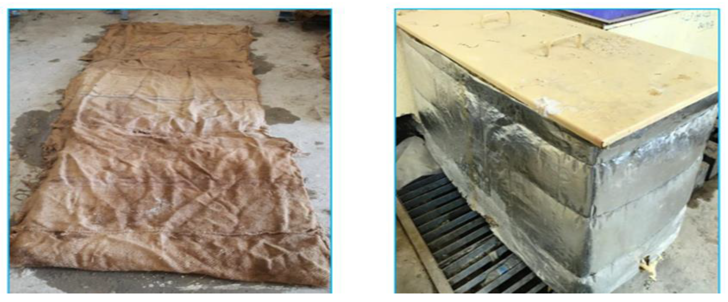
  • At the end of the casting process, and after that, the top surface of each specimen is finished off; polyethylene sheets are used to cover the molded samples to prevent any loss of moisture. The specimens are left in the casting room for (72 h) at a temperature of (25 ± 2 °C) until the specimens are demolded (see Figure 6).
  • Finally, burlaps are used to cure the plate specimens using saturated wet coverings. The samples are cured in water tanks at a temperature of (23 ± 2 °C), as presented in Figure 6.

2.4.1. Steel Plate Strengthening Procedures

The purpose of testing the reference plate specimen is to estimate the ultimate loading and deflection features. Before strengthening, all plates are loaded up to half the ultimate load of the control samples. When the concrete reaches an age of 8 weeks, the plate tension surfaces are penetrated using drills to allow steel plates with shear bolts to be placed beneath, as shown in Figure 7a. Using a hammer drill, the slabs undergo pre-drilling in light of a specific bolt distribution. Next, the plate surface is roughened using steel brushes to weld the steel shear bolts onto the plates at the specified locations, as illustrated in Figure 7b. After this process, a vacuum cleaner is used to clean the plate surface and holes carefully. The steel plate surfaces are checked to ensure that they are free from oil and dust using a suitable solvent to prepare them for applying the two-part epoxy adhesive. Next, the steel plate is bonded onto the concrete surface at the bottom (tension) side using the epoxy bonding agent. Finally, the steel bolts are put into the epoxy adhesive (using the same bonding material) before being inserted inside the holes. A curing period of (7) days is followed before testing the strengthened plates.

2.4.2. SIMCON Laminate Strengthening Procedure

The third group of slab specimens was strengthened using SIMCON laminates. SIMCON takes the form of a pre-placed interwoven mat of steel fibers, which are infiltrated using cement slurry. As for the experiment conducted in this study, six different sizes of SIMCON mats are used, namely (500 × 500 mm), (750 × 750 mm) and (1200 × 1200 mm), each of which is provided in two thicknesses (20 mm) and (30 mm). In all cases, the SIMCON mat is placed within a prepared mold of the desired dimensions, after which the concrete mix is poured into the mold, as shown in Figure 8. As soon as the SIMCON reaches the initial stage, the NSC plate specimen is cast upon the SIMCON laminate, having a square plan with an overall side length of (1200 mm) and a thickness of (50 mm). After 24 h, the slabs are removed from the mold to undergo a curing process for 28 days to obtain the necessary strength.

2.5. Test Set-up and Instrumentation

Two days before testing, the slab specimens are taken out of the immersed basins, thoroughly cleaned, and left to dry. Then, a white emulation coat is applied to clarify the view of any cracks. The same setup is used for the application of two types of loading (cyclic and impact), whereby the test slab specimens have ideally simple support. Figure 9 shows the support frame created especially to be put inside the test machine. It consists of six (W) steel beams (W6 × 15, W10 × 22), whose welding and arrangement form them into a square shape. The plate edges are supported using (25 mm) steel bars that are welded upon the upper surface of the steel beams. All slab specimens undergo testing at the age of (90 days) under cyclic and impact loading up to failure.
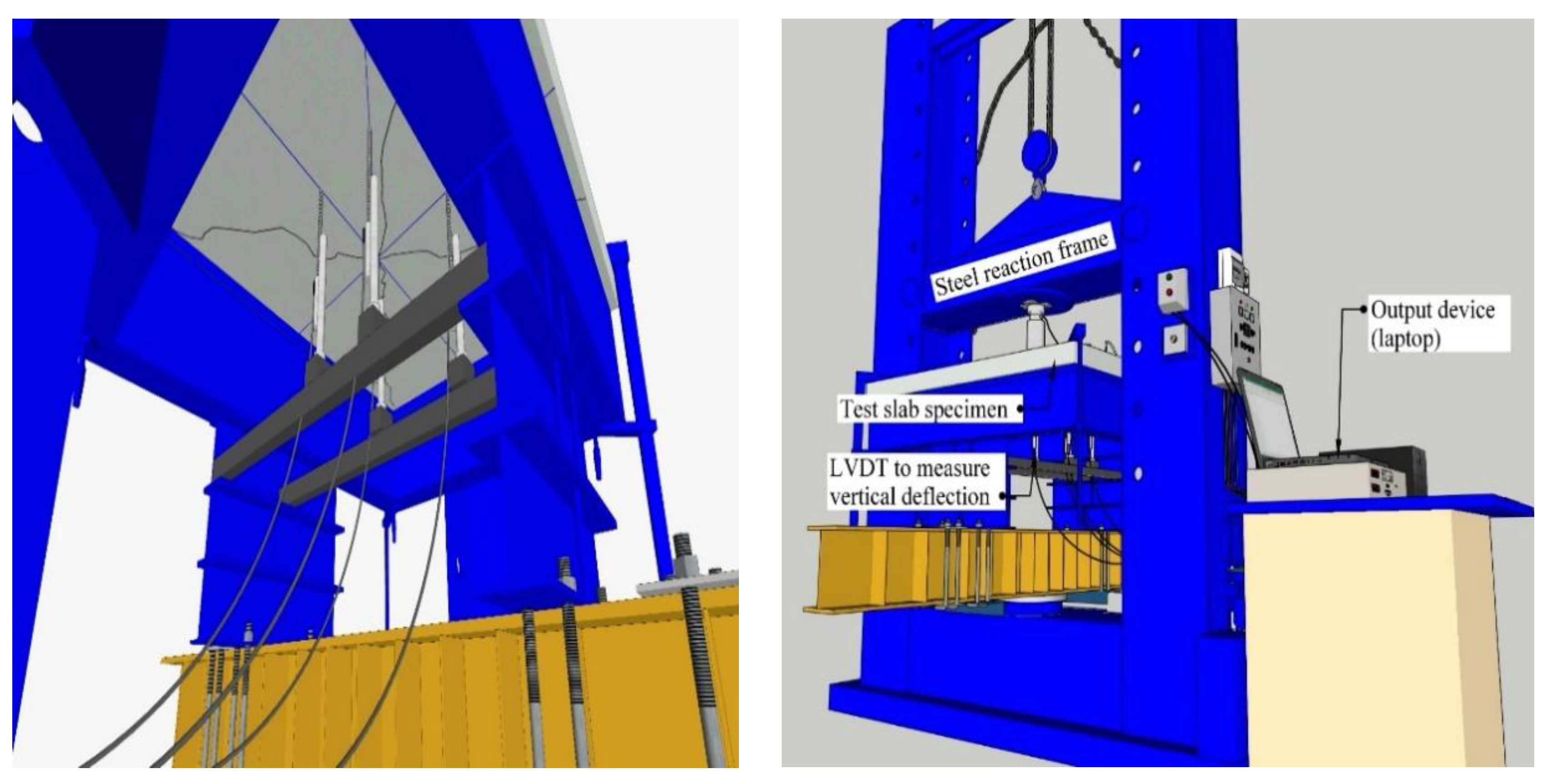
In both tests of deflection measurement at the plate center and quarter of spans, a Linear Variable Differential Transformer (LVDTs) shown in Figure 10a with a 50 mm maximum capacity is used. In addition, a crack width meter, which is shown in Figure 10b, is utilized to study the development of crack width with the applied force. The microscope accuracy was 0.05 mm. The data was recorded by connecting the load cells and LVDTs to a data logger of sixteen channels, as presented in Figure 10c.

2.5.1. Cyclic Loading Test of Plates

In this type of loading test, the slabs are labeled and put along the edge onto the simple support. The specimens were centrally loaded using a loading plate with dimensions of (100 mm × 100 mm). The lifting, horizontal installation, and removal of specimens out of the loading frames were done using a 10-ton capacity crane (see Figure 11). During the cyclic loading test, hydraulic jacks that are placed at the bottom of the plate specimens are responsible for loading the slabs from a mid-point upwards. The applied load is measured using the additional load cell that is put between the jack and the sample. The load application is performed using high-strength steel plates that have a dimension of (100 × 100 × 10 mm). They are put onto the contact points, as shown in Figure 11.
The pre-defined displacing routine includes about (20–22) cycles of displacement that are fully reversal. An incremental increase is seen in the peak displacement value until it fails, rising from a (0.25%) drift up to (7%). Figure 12 illustrates the drifting routine during the cyclic displacement in this experiment [39]. There are several initial displacements found as part of the drifting routine. The purpose of them is to study the slab’s initial elasticity response. All slabs undergo the exact same vertical loading sequences. Twenty cycles of repeated load are applied to five slabs. At every cycle, the connection is loaded slowly up to 70% of the ultimate load of the reference specimens, after which it is unloaded, as in [40]. Lastly, the specimens are loaded up to failure. Each load at the first crack, ultimate punching shear/bending load, and corresponding deflections at the slab center are noted as part of the experiment’s observations and records. Figure 13 illustrates the set-up of the slab specimens mentioned.

2.5.2. Impact Loading Test of Plates

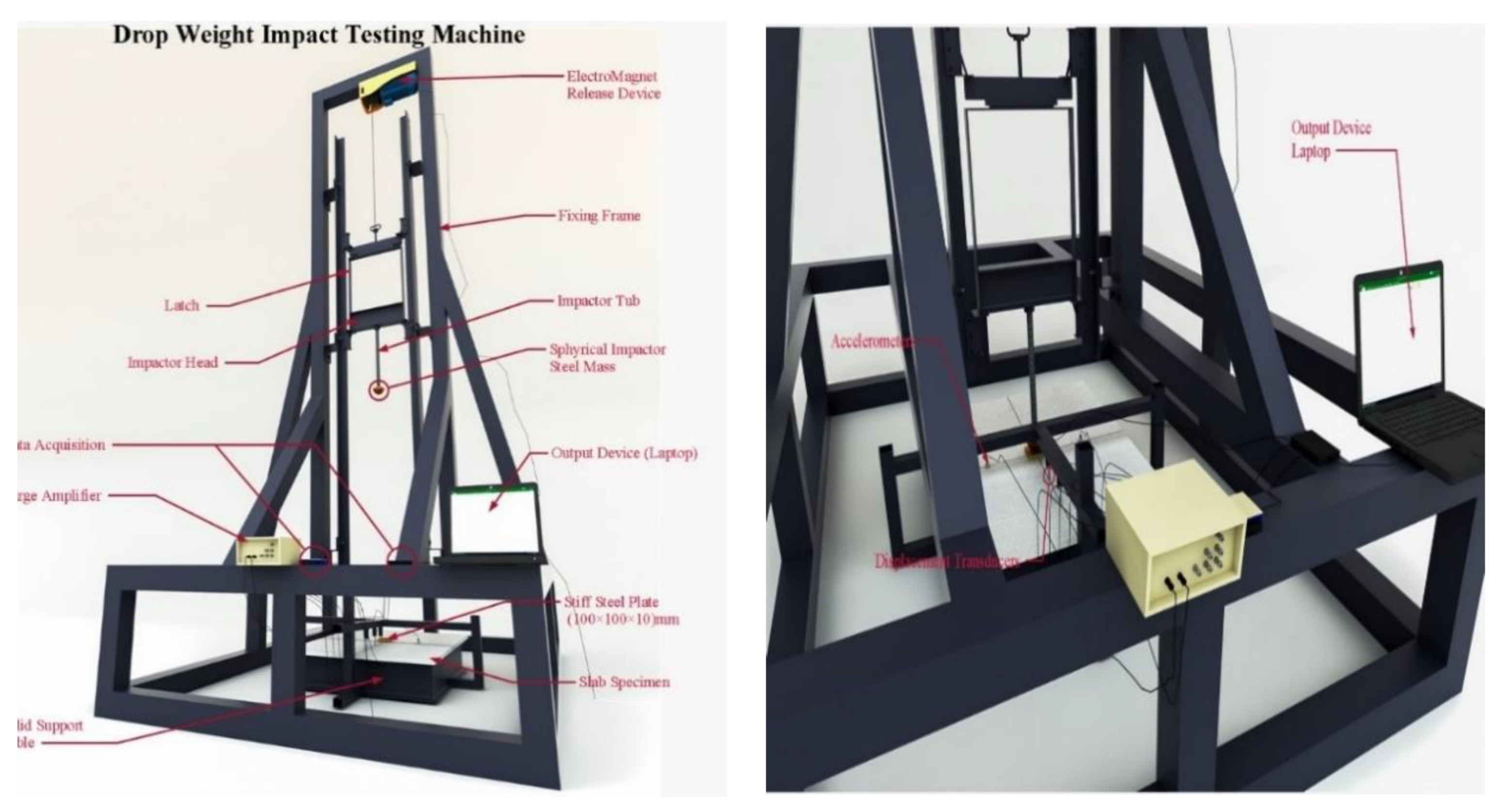
Moving forwards to the impact loading tests, this type of loading was achieved through free fall, dropping a weight from a height of (1.5 m) (see Figure 14). The dropped weight slides between tracks from the drop tower to impact the specimen at its center point. The semi-spherical impact hammer head utilized in this process is made from high-strength steel. The constants throughout the test are the drop height, hammer weight, and geometry of the hammerhead. Local fracturing is prevented using high-strength steel plates of (100 ×100 × 10 mm), which are put over the contact points for distributing the load identically to the ones used in cyclic tests. In addition, polyurethane rubber parts are put between the loading plate and the specimen. The slab specimens are put in the impact loading testing set-up using the special steel supporting devices in this experiment.
The (84 kg) hammerhead drops from a (1500 mm) height to create an impact load onto the contact point, implying that an equal amount of input energy affects the specimens (9.81 × 84 × 1.5 = 1.2361 kJ). The hammer weight, drop height, and impact energy level are chosen in such a way that they are suitable to trace the damage that occurred in the test specimens. The Integrated Circuit Piezoelectric (ICP) dynamic load cells are used for measuring the impact loading that affects the specimens. This load cell is found inside the hemisphere part of the hammer-dropping apparatus. The vibrating motions that are affected by the impact loading are measured using accelerometers linked to the slab samples. The purpose behind the measurement of vibrating behavior is that determines how the test slabs behave dynamically under impact loading, obtaining constant energy. The dynamic behavior changes as a result of the change in variables. Two piezoelectric accelerometers put onto a test specimen will have a capacity of (5000 g). The placement of the accelerometers is separated by certain distances away from the axis intersection of the test specimen, which is subjected to the impact load. Since impact loading occurs suddenly rather than being simply static or dynamic, multiple measurements are made within a short time through the dynamic data-logger system. Therefore, this experiment deploys dynamic data-logger systems that are agreed upon on a global level. For each specimen, the measurement of one dynamic impact loading, two accelerations, four displacements, and four strain values are obtained, collecting 25,000 data per second (25 kHz at each channel). The crack patterns were marked by using a marker at each increment of load.

3. Numerical Modeling and Experimental Results

There are a number of essential characteristics considered when analyzing reinforced concrete structures to determine how accurate, efficient, and economical the used method is. The FE method is therefore considered to be versatile and effective. In this method, the analysis accuracy is mainly based on the element types adopted in representing the problem, as well as the suitable modeling of materials properties and the applied boundary conditions. At the present time, the finite element method has developed into a strong computing tool used in carrying out complicated non-linear response analyses for reinforced concrete structures in a routine manner. The FE analysis mainly aims to determine the structure’s response under loading [41]. A non-linear FE analysis is executed to emulate and analyze the slabs tested in this work. A comparison of the experimental and numerical investigations is also offered to examine whether the slab modeling is sufficient, and it includes the element type, material characteristics, constants, and convergence research.

3.1. Modelling and Analysis of Slab Specimens

The ABAQUS finite element algorithm creates a non-linear FE model for simulating the behavior of NSC specimens strengthened with steel plates or SIMCON under cyclic and impact stresses. The predicted ultimate load-carrying capacity versus vertical deformation responses are put into comparison with the lab results that correspond with it, as obtained during the FE analyses of the tested slabs. All specimens were modeled in three dimensions to investigate the load-carrying capability and behavior of slabs. There are two types of NSC specimens used in this work, each consisting of three parts. The first type consists of primary concrete reinforcement, followed by transfer reinforcement (to transfer the load between two structural elements) and SIMCON, whereas the second type consists of primary concrete reinforcement, transfer reinforcement, and steel plates. The finite element model was loaded at identical places for all slab specimens in the experimental investigation as a uniformly applied pressure.

3.2. Finite Element Mesh and Boundary Conditions

It has been observed that the majority of the mesh intensity determined the analysis complexity levels and processing timespan. It was, therefore, necessary to perform a preliminary analysis of different mesh densities to determine the best mesh density which would provide the desired accuracy. In practice, this is achieved whenever increasing the mesh density does not influence the outcomes. To study convergence, the number of elements was increased in each of the X, Y, and Z directions. The plates were modeled while decreasing the element size (30, 25, 20, 15, 10, and 5), with the number of elements being (891, 1400, 2300, 3484, 9500, and 80,600), respectively. Another aspect noted during observation is the axial displacement for the same applied loading levels. The convergence study shows that reducing the mesh size from (10 mm) to (5 mm) enables the change in axial displacement to be neglected. The axial displacement value increases in accuracy with experimental data (see Figure 15). Therefore, a 10 mm element size was set for the mesh density, guaranteeing that the element size and the numerical solution stability are adjusted reasonably.

3.3. Cyclic and Impact Analysis Model

The structural analysis of the plates was performed using a single impact and general cyclic analysis step. The modeling of NSC plates strengthened with either SIMCON or steel plates involves three-dimensional solid elements that are marginally integrated into the concrete modeling using 8-node brick elements (C3D8R). In NSC plates, the reinforcement involves a three-dimensional two-node truss element (T3D2). A consistent pressure was applied to each slab’s top, whereby the slab remains fixed at its outer edges, restraining displacement in all directions (X, Y, and Z axes). The center of the slab remains restricted to movement on the X and Z axes, whereas the displacement is not restricted in the direction of the slab’s vertical axis (Y-axis). The top of the slab undergoes a uniform loading, as demonstrated in Figure 16.

3.3.1. Punching Shear

There are a number of factors that influence the punching shear strength of plate specimens that have no specific shear reinforcement. They include the thickness of slabs, strength of concrete, loading area aspect ratio, and flexural reinforcement ratio. These factors are addressed in a number of simplified equations used to predict the shear punching capacity. The aforementioned approaches contribute to the punching shear strength of SIMCON or steel plate-strengthened specimens.

3.3.2. American Concrete Institute Building Code ACI 318-14

The American Concrete Institute Building Code ACI 318-14 does not take into consideration the impact of the flexural reinforcement on the shear punching capacity of RC slabs. This capacity could be obtained for normal-weight concrete by taking the smallest value of any of the following formulae [42].
Q u p = f c 3 b o d
Q u p = ( 2 + 4 β c ) f c 12 b o d
Q u p = ( 2 + α s d b o ) f c 12 b o d
where Qup represents the shear punching capacity; bo stands for the perimeter of the critical section at a distance d/2 from the face of the loading area; d is the effective depth of the slab; αs represents a coefficient that is equal to 40 for internal columns; βc is the ratio of long to short sides of the loading area; and f’c is the concrete cylinder strength.

3.3.3. British Standard Institution BS 8110-1985

The value of Q u p can be obtained via the formula below, which takes into consideration the flexural reinforcement ratio, meanwhile leaving out the impact of the loaded area aspect ratio [43].
Q u p = 0.79 100 ρ 3 400 d 4 b o d
whereby ρ represents the reinforcement ratio (limited to 0.03); bo represents the rectangular critical section perimeter at a distance of 1.5 d from the face of the loaded area; (400/d) must remain minimally 1.0; and Qup could be multiplied by (fcu/25)1/3 when dealing with concrete compressive strength fcu over 25 N/mm2.

3.3.4. Eurocode 2-2004

In this code, Q u p is obtained via the equation below, taking into consideration the flexural reinforcement ratio and neglecting the impact of the loading area aspect ratio of the loaded area [44].
Q u p = 0.18 k 100 ρ f c 3 b o d
whereby k = 1 + 200 d and must not exceed 2; ρ represents the reinforcement ratio (limited to 0.02); and bo is the perimeter of the critical rectangular section with round corners a distance 2d from the face of the loaded area.

3.4. Dynamic Analysis

The ABAQUS FE-analysis software has been adopted for dynamically analyzing the specimen under impact effect [45]. Solutions are obtained using the explicit module, as it provides the highest accuracy in the incremental dynamic analysis [46,47]. Therefore, the NSC slabs strengthened by SIMCON and steel plates having different cross-sections and thicknesses undergo constant impact loading. One specimen is left non-strengthened, whereas the rest are strengthened using either SIMCON or steel plates. First, the process starts by modeling each of the specimens and testing the set-up into the software to create 3D models. The drop heights, steel hammer mass, SIMCON and steel plate, and reinforcement support conditions are all configured within the program of the experiment, followed by assigning the material properties to related sections.
The experimental specimens that are strengthened by SIMCON or steel plates are modeled using Concrete Damaged Plasticity (CDP), which is a damage model for concrete characterized by their continuum, plasticity-based features. Since this model is already found within the ABAQUS software, it regards the uniaxial tensile/compressive responses of concrete as being damaged plasticity (see Figure 17). In the case of uniaxial tension, the responses of stress-strain tend to follow a linear elastic relationship until the failure stress. In addition, in the same conditions, this response remains linear until the initial value (σc0) is reached. As for the plastic behavior, the stress hardening and strain softening over the maximal stress ( σ cu) characterized the responses [45].
The CDP model takes the elastic stiffness degradation into consideration via two damage factors: dt and dc. These variables range between 0 < dt, dc < 1, whereby (0) represents material that is not damaged, and (1) indicates the strength being totally lost. Thus, the relation of stress with uniaxial tension and compression loadings can be illustrated through the following equations, respectively:
σ t = ( 1 d t ) E 0 ( ε t ε ˜ t p l )
σ c = ( 1 d c ) E 0 ( ε c ε ˜ c p t )
The efficient tensile and compressive cohesion stress values that determine the yield surface size could be described as follows:
σ ¯ t = σ t ( 1 d t ) = E 0 ( ε t ε ˜ t p l )
σ ¯ c = σ c ( 1 d c ) = E 0 ( ε c ε ˜ c p l )
where E0, ε ˜ t p l , ε ˜ c p l represent the initial values of material elastic stiffness, and the equivalent plastic strains in tension and compression, respectively. The tension and compression stresses are provided as cracking and non-elastic strain functions ( ε ˜ t c k and   ε ˜ c i n , respectively) to define the tension and compression post-failure behavior in RC. The cracking and non-elastic strains could be described as the whole strain except the elastic strain that corresponds to the materials that are not damaged, as presented in Equations (10) and (11) below.
ε ˜ t c k = ε t σ t E 0
ε ˜ c i n = ε c σ c ε 0
After providing the unloading data to ABAQUS for tensile and compressive damage curves (dt ε ˜ t c k and dc ε ˜ c i n , respectively), the cracking and non-elastic strain values are converted to equivalent plastic strain curves by ABAQUS using the Equations (12) and (13) below [45]:
ε ˜ t p l = ε ˜ t c k d t 1 d t σ t E 0
ε ˜ c p l = ε ˜ c i n d c 1 d c σ c E 0
The Equations (12) and (13) can be rearranged as follows [48]:
d t = 1 σ t / E 0 ε ˜ t p l ( 1 b t 1 ) + σ t / E 0
d c = 1 σ c / E 0 ε ˜ c p l ( 1 b c 1 ) + σ c / E 0
whereby the equivalent plastic strains are ε ˜ t p l = bt  ε ˜ t c k and ε ˜ c p l = bc  ε ˜ c i n , respectively. The previous experimental studies recommended bt and bc as 0.1 and 0.7, respectively [49]. The CDP model is determined by five plastic parameters that define each of the yield surface functions, potential flows, material viscosity, and the concrete compressive and tensile behavior. These parameters (ψ, σboco, Kc,µ) include the dilation angle, flow potential eccentricity, the initial equibiaxial to uniaxial compressive yield stress ratio, and deviatoric cross-section coefficient, and the viscosity parameter [48]. The work in [50] further developed the yield functions used in CDP. As for Lee and Fenves [51], they involved further modification of the aforementioned yield function for obtaining differing strength evolutions in tension and compression. Equation (16) below defines this yield function [45].
F & = 1 1 α ( q ¯ 3 α p ¯ + β ( ε ˜ p l ) σ ¯ m a x γ σ ¯ m a x ) σ ¯ c ( ε ˜ c p l ) = 0
α = & ( σ b 0 / σ c 0 ) 1 2 ( σ b 0 / σ c 0 ) 1
γ = 3 ( 1 K c ) 2 K c 1
β ( ε ˜ p l ) = σ ¯ c ( ε ˜ c p l ) σ ¯ t ( ε ˜ t p l ) ( 1 α ) ( 1 + α )
whereby α and γ are constants of no dimension obtained by σbo/σco and Kc parameter. q ¯ , p ¯ and σ ¯ max represent the stresses of Mises equivalent effectiveness, hydrostatic pressure, and the maximal principle effectiveness, respectively. The Drucker-Prager hyperbolic function is used in the CDRP model as the flow potential (G) and can be described as:
G = ( e σ t 0 tan ψ ) 2 + q ¯ 2 p ¯   tan ψ
where σ t0 is the ultimate uniaxial tensile stress [48]. The compressive behavior of concrete is defined using Mander’s stress–strain model for undefined concrete [52].
f = f c x r r 1 + x r   for   ε 2 ε c
f = ( 2 f c r r 1 + 2 r ) ( ε c u ε ε c u 2 ε c )   for   2 ε c < ε ε c u
where
X = ε ε c ´
R = E E ( f c ε c ´ )
ε represents the concrete strain, f is the concrete stress, and E represents the modulus of elasticity. The latter can be obtained using the formula E = 4700 f ´ c whereby f ´ c indicates the concrete compressive strength, ε ´ c represents the concrete strain at f ´ c (being 0.002, assumingly), and ε cu stands for the ultimate concrete strain (being 0.003, assumingly). The concrete tensile behavior is modeled as linear elastic until ft is reached, which could be obtained using f ´ t = 0.623 f ´ c [48]. After that, the post-cracking behavior is modeled using Equation (26) below [53].
f t = E ε t   for   ε t ε c r
f t = f t ( ε c r ε t ) 0.4   for   ε t > ε c r
where 𝑓t represents the tensile stress, and ε t and ε cr represent the tensile and cracking strains, respectively, for the ultimate tensile strength.
The tensile and compressive behavior of concrete under impact loading depends on the strain rate. Higher strain rates indicate a remarkable enhancement of concrete strength. This increases the significance of strain rate in the prediction of reliable dynamic responses. The strain rate impact can be indicated using the dynamic-to-static strength vs. strain ratio, also known as the dynamic increase factor (DIF). Several formulas can empirically express the aforementioned strain rate impact [54,55], which in turn has an easy implementation in concrete models within ANSYS and LS-DYNA software [56,57]. Given that CDP models cannot take the rate-dependent concrete behavior into consideration automatically, the various tension stiffening and compression hardening curves need to be manually provided in the form of tabular functions of cracking and inelastic strain rates, respectively [45]. In addition, this approach does not have a perfect application of strain rate impact upon all aspects of concrete behavior [58]. Previous works propose a simplified approach whereby uniaxial curves update all iterations via DIF and the calculated strain rates until achieving adequate convergence. It has been shown that this approach obtains reasonable results only until the first response peak, whereas it becomes rather inaccurate in post-peak responses. Therefore, the decision has been made not to include the concrete strain rate impacts within the FE model for this work due to the fact that the CDP model has no automatic algorithmic coverage for experiencet.
Table 2 illustrates the elastic modulus, Poisson’s ratio, and the ultimate tensile stress and plasticity parameters for CDP definition, as introduced in previous works [59,60]. Elastic-perfectly plastic material models are used for defining steel reinforcement, whereas linear elastic models are used for modeling the steel hammer and loading plates. The material properties of the aforementioned elements are also stated in Table 2. The embedding of reinforcement within slabs and tie contact property provides a total adherence between the slab and the reinforcement.
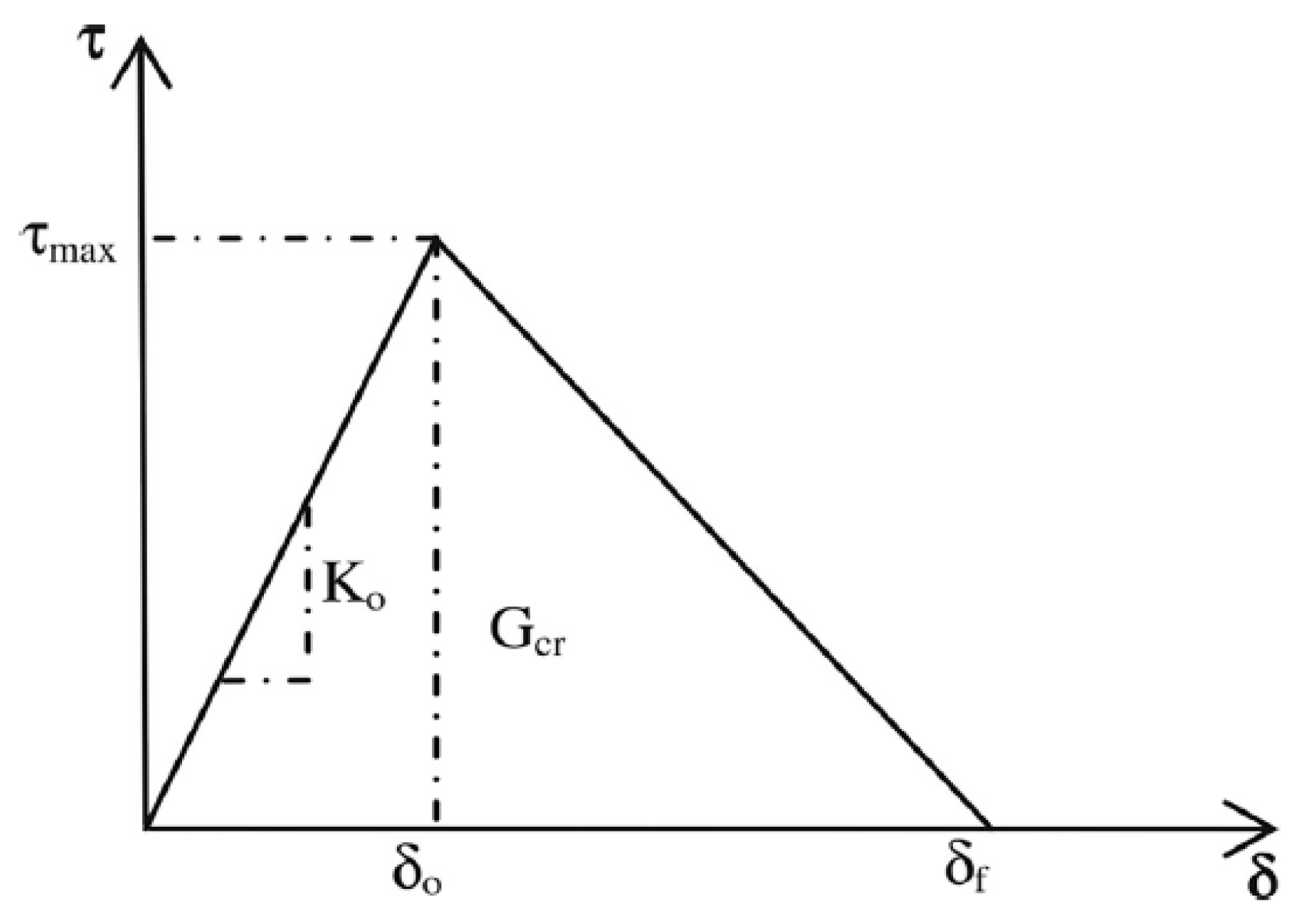
The elastic modulus and Poisson’s ratio for SIMCON and steel plates are taken as 231,000 Mpa and 0.45, respectively. The former was reduced to 15% of the rate adopted in the fiber direction, and the latter was set as 0.3, assumingly. A cohesive modeling zone on a bilinear traction-separation law is used to model the interface between the SIMCON steel plate and concrete. This law could be described using the effective traction τ , and effective opening displacement δ (Figure 18). Figure 18 indicates that each of the stiffness K0, local material strength τ max, opening displacement for fracture δ f, and the energy needed to open crack Gcr are applied in defining the τ - δ relationship. Gcr represents the area under the τ - δ curve. The definition of K0 is represented in Equation (27) [61].
K 0 = 1 t i G i + t c G c
whereby ti and tc represent the thicknesses of epoxy and concrete, respectively. Gi and Gc represent the shear modulus of epoxy and concrete, respectively. τ max = 3 Mpa is considered because of the lack of debonding within the experiment [61]. The assumption is made that the damage is an initiation of a quadratic traction function that includes the nominal stress reaching the value (1). This requirement could be described as follows [45,61]:
( σ n σ n 0 ) 2 + ( τ n τ s 0 ) 2 + ( τ t τ t 0 ) 2 = 1
where σ n, τ s, and τ t are the interface’s cohesive, tensile, and shear stresses, respectively. N represents the normal direction of stress components, and n and s represent their transverse directions. The Benzaggah–Kenane fracture requirement found in ABAQUS is used to evaluate the interface damage. It is especially beneficial whenever the critical fracture energies of the first and second shear directions are equal ( G s c G t c ) [29,46]:
G n C + ( G s C G n C ) ( G s + G t G n + G s ) n = G C
whereby Gn, Gs, and Gt represent the work of traction and conjugate separation within the normal, first, and second shear directions, respectively. N is the material parameter. Table 3 presents the cohesive zone modeling variables utilized for the SIMCON, steel plate, and concrete interfaces [61].

3.4.1. Time History of Impact and Reaction Forces and Deflection of Slab Specimens

Based on the results of the experiment, no correlation was found between the maximal impact force and the support conditions. The numerically obtained curves of the time history did not differ much from the experimentally obtained ones, whereas the numerically obtained maximal impact force was less than the experimentally obtained value. With regards to the reaction force, both the time and deflection histories did not indicate any major differences in shape. Furthermore, the maximal deflection of plates did not appear to be conditioned by the boundaries. The impact tests indicate the significance of the inertia forces. Based on the force-time history of the test, the impact force appears to undergo resistance throughout the inertial force of SIMCON plates initially. The forces that are created at the supports tend to increase in prominence during the post-impact stage, reaching their equilibrium. In addition, the measurements indicate great similarities in terms of reaction force, yet there are variations in terms of impact force and magnitude-to-mass times acceleration values.
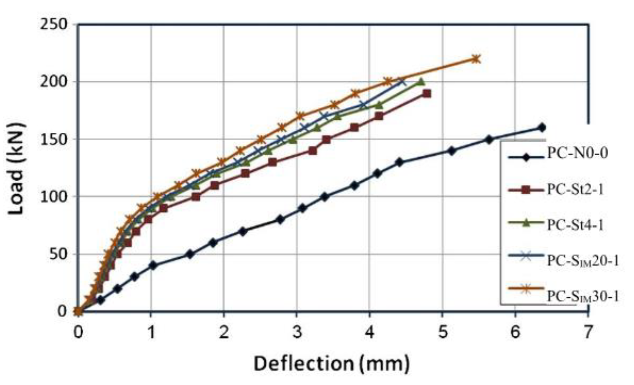
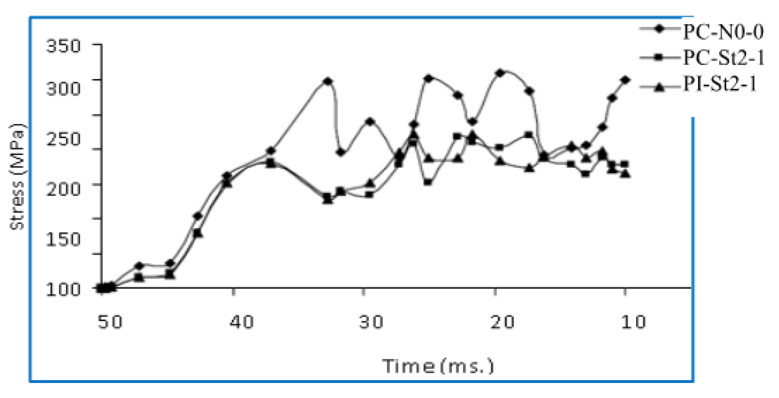
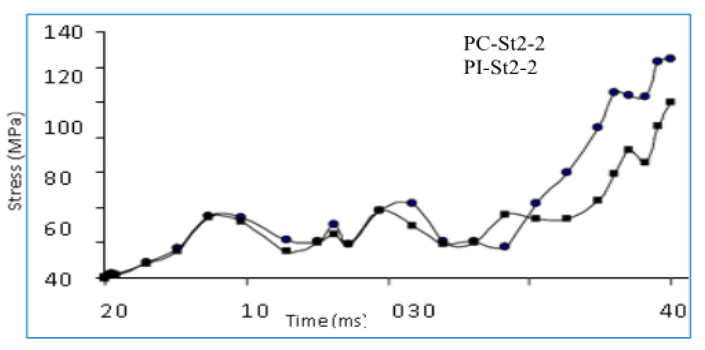
The deflection of strengthened specimens is found to be less than the values obtained for the control specimens, as shown in Figure 19. The reason could be traced back to the fact that steel plates increase the stiffness of RC slabs and, eventually, their composite action. The decrease in deflection measurement can be quantified using listing all deflection rates at a fixed base load (P = 158 kN) for the test specimens, as shown in Table 4. The maximal loading value was set to be the base load for the control specimens when recording the deflections. The aforementioned Table indicates the deflection rates between the strengthened control specimens in percentages, being between (43–57%) of the control specimens. It has been observed that the increase in steel plate size results in an increase in the total slab stiffness. A slight difference in stress values of different steel plate thicknesses is observed, as shown in Figure 20, Figure 21 and Figure 22. The essential parameter that influences the overall results of slab specimens strengthened with steel plates is the suitable location of steel plates.

3.4.2. Strain Gauge Measurements of SIMCON Plates

The strains of slabs that are strengthened using SIMCON were measured at 8 locations for each specimen, as shown in Figure 23. However, the excessive noise led to the inability to collect reliable data from the gauge during the cyclic tests. This issue was partially solved in the impact test so that sufficient data could be obtained. During the impact tests, the plates underwent deflection both upwards and downwards because of the nature of the impact event. The expectation was made that there would be both tensile and compressive strain measurements. However, the majority of strain gauge measures indicate tensile forces only. This observation could have many possible explanations, including the following: (a) Due to various waves propagating in the plate as a result of the impact, specific points at which the strain gauges are placed may experience tension only, whereas other points at which strain gauges are not placed and therefore not recorded, could actually experience compression (b) The probability of loss of contact may cause different dynamic behavior than the expected one. The strain gauges at the bottom of plates tend to measure higher peaks and residual strain values than the ones located on top during the impact tests. To exemplify, the strain gauges of SIMCON-strengthened plates indicate that negative values were obtained at the bottom face strains during impact; meanwhile, the top surface strains obtained positive values. This could indicate that the plates tend to show deflection upwards during impact, eventually causing compression on the bottom surface as opposed to the tension on top during the impact. Table 5 below presents the peak loads for each test, along with a comparison of the control slab values and those of the strengthened specimens, indicating the amount of increase or decrease.

3.5. Finite Element Analysis Results and Discussion

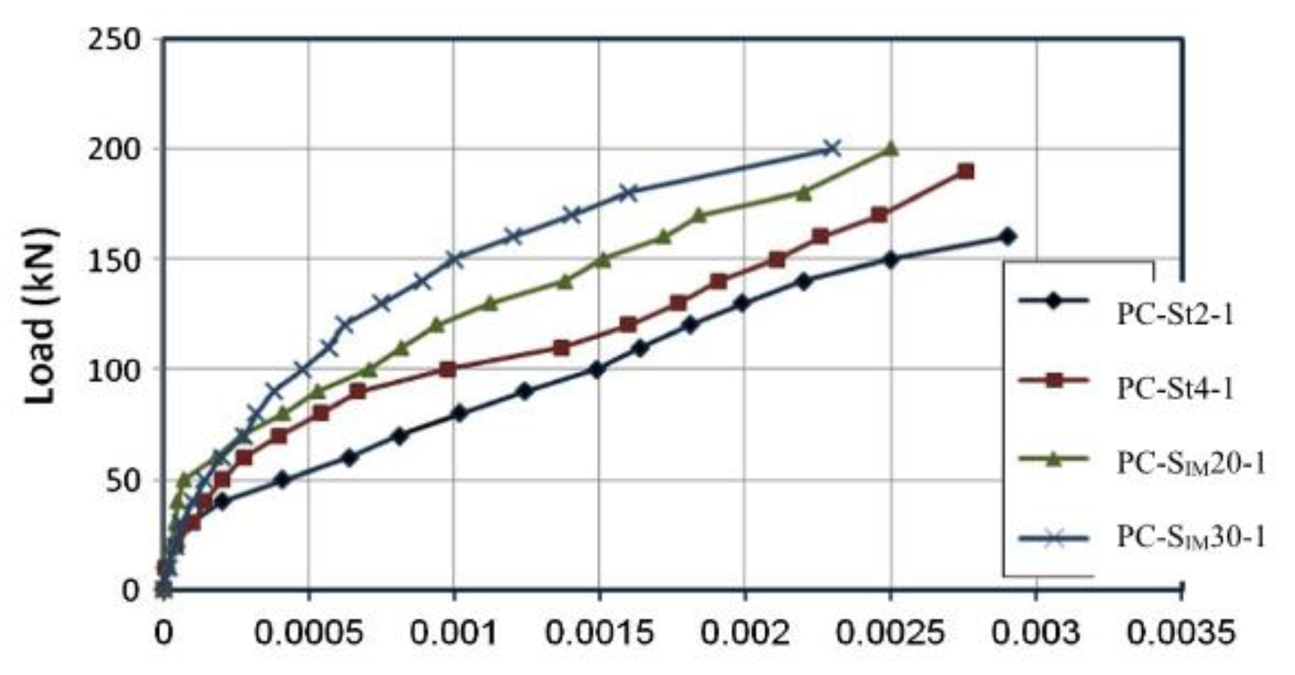
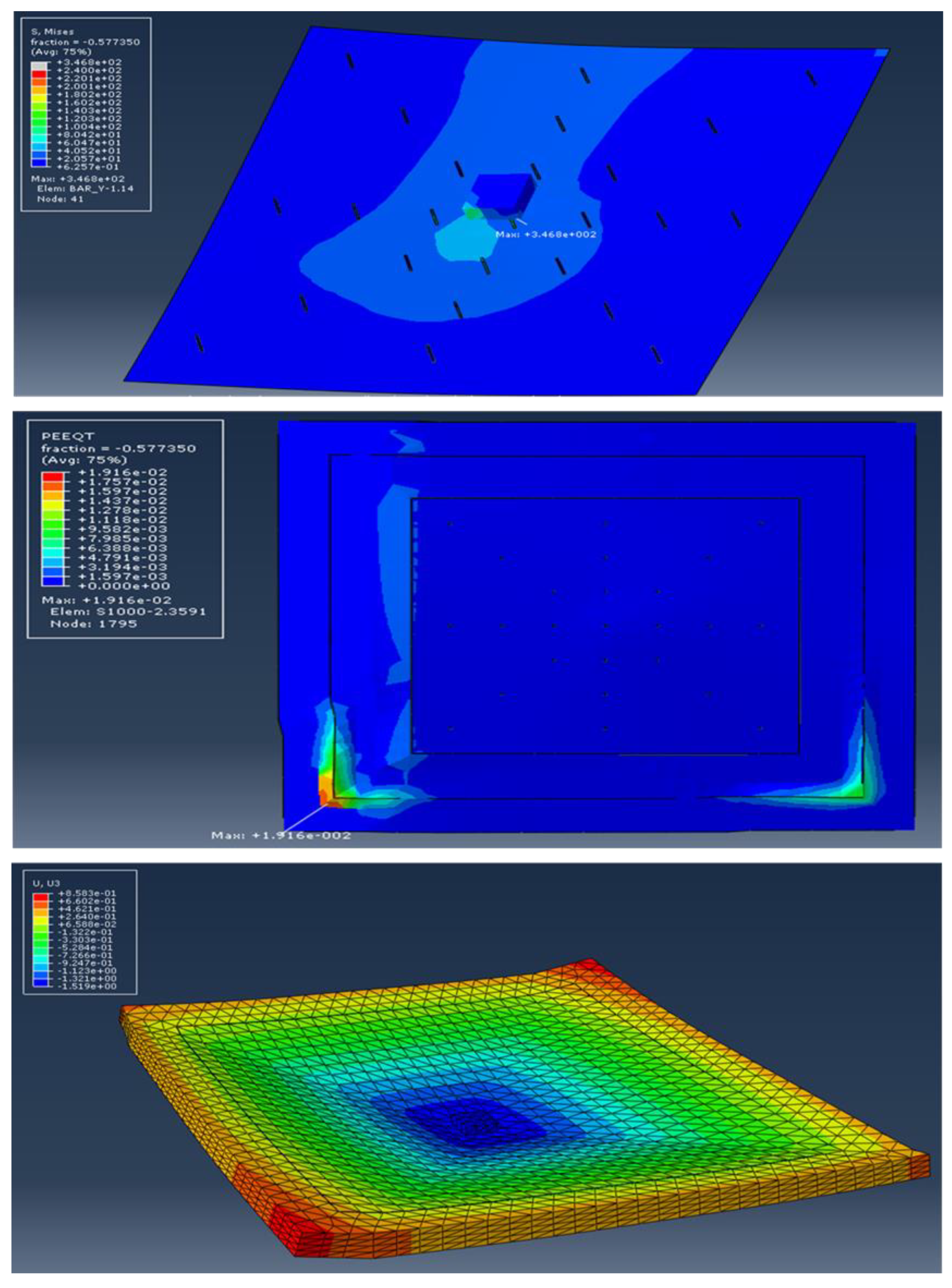
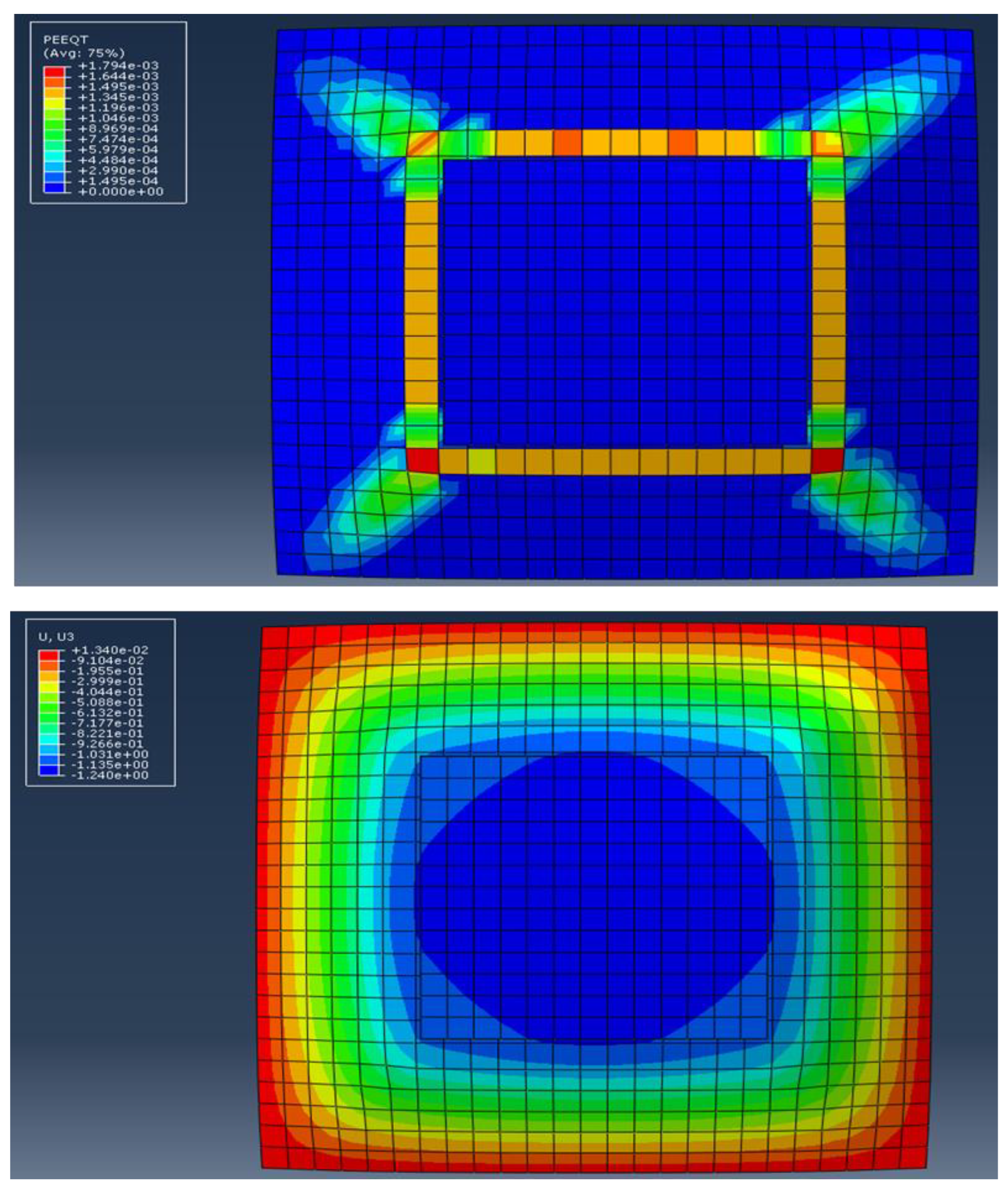
The numerical analysis is adopted for verifying the results of the experiment. In Figure 24, Figure 25 and Figure 26, the axial displacement and ultimate static loads (load at failure) of tested plate specimens are put into comparison with the numerical results from the FE analysis. These graphs show how the strengthening type, cross-section, and SIMCON thickness affect the slabs. Figure 27 illustrates how the axial displacement (U) and plastic strain (PEMAG) vary for slabs subjected to cyclic loading.
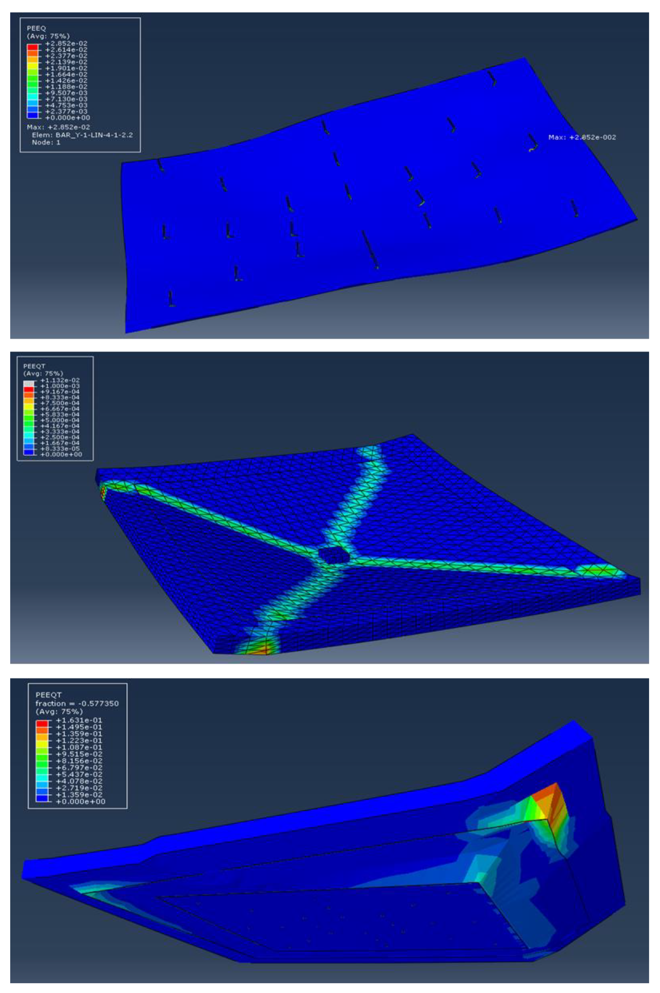
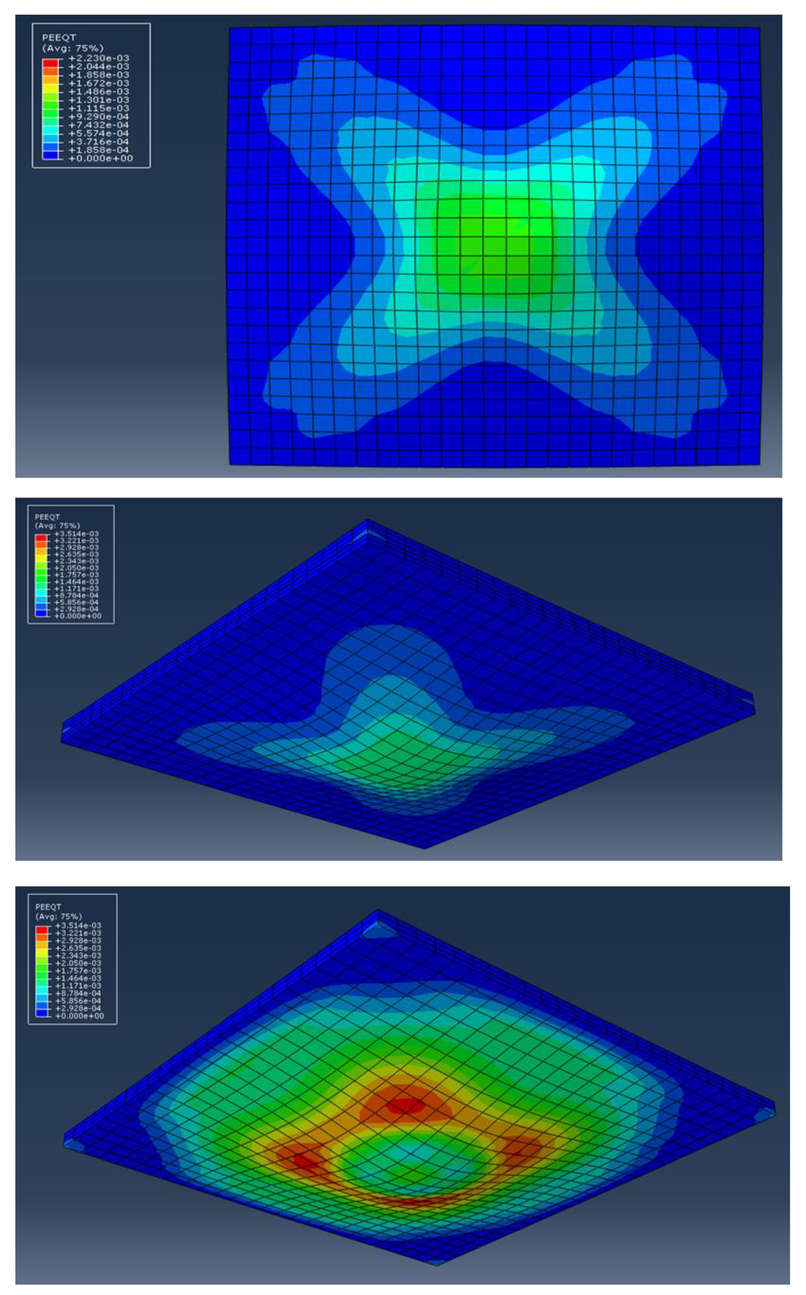
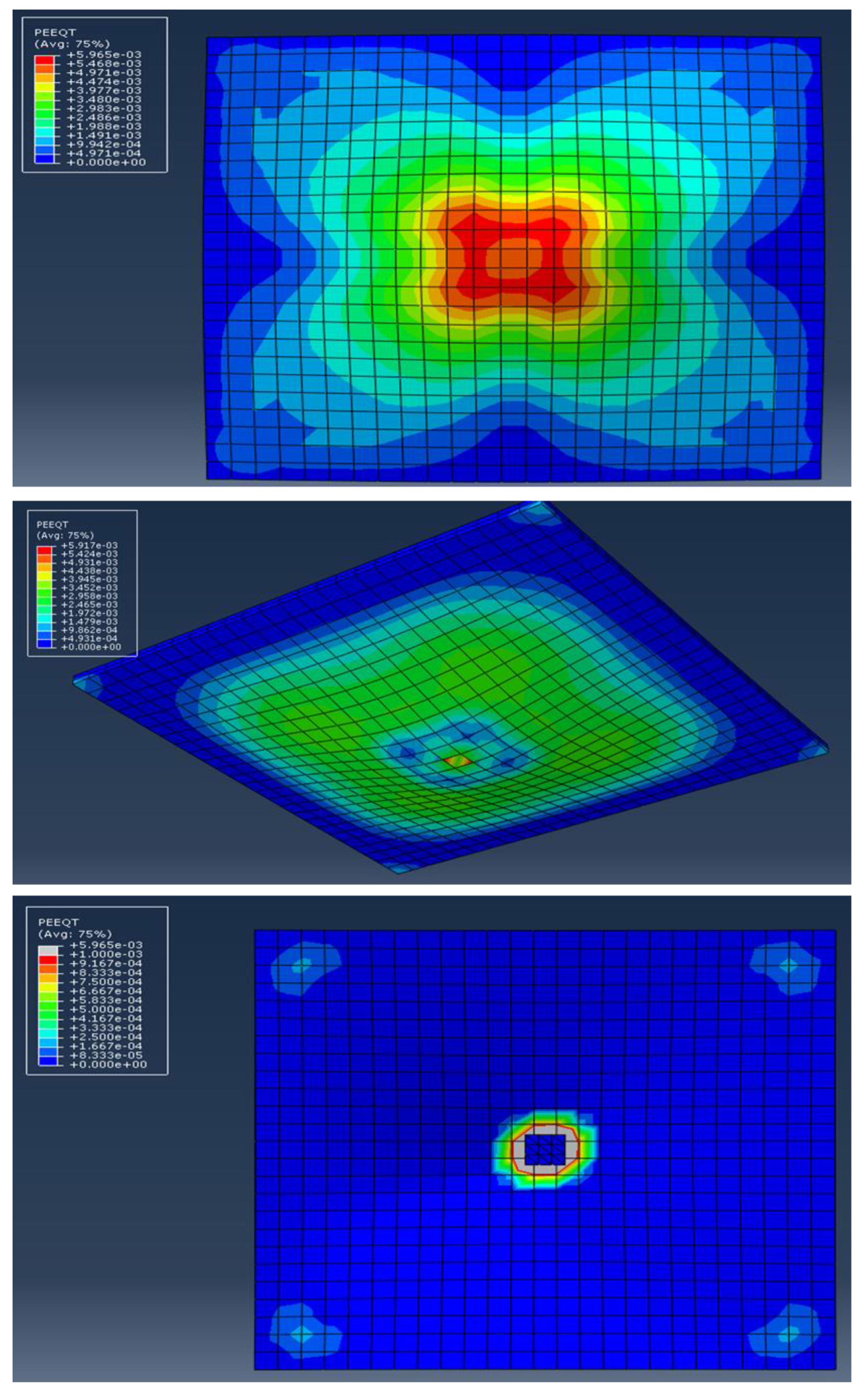
Figure 28, Figure 29, Figure 30, Figure 31 and Figure 32 show the crack pattern distribution at the bottom surface for slabs under impact load. The numerical result shows that the slab thickness of SIMCON significantly affects the load-carrying capacity, and it increases with the increase in thickness. In addition, the use of strengthening from steel plates gives a higher load-carrying capacity. It can be seen from these figures that the stiffness of slabs strengthened with SIMCON is higher in comparison with slabs that are strengthened with steel plates. Moreover, it can be noticed from the axial load-displacement relationships that all numerical models show a stiffer behavior when compared with the experimental axial load-displacement relationships. Moreover, the experimental and numerical results indicate that the slabs strengthened with SIMCON of (20 mm) provide higher results than those strengthened with steel plates. The most probable explanation for an adverse consequence is the presence of micro-cracks generated by drying shrinkage while fabricating the slab specimens; this will reduce the stiffness of these specimens, whereas these micro-cracks are missing in the FE model. Furthermore, the FE analysis considered concrete to be a homogenous material in all model directions; meanwhile, in reality, concrete is a heterogeneous material. Again, the careful modeling of support circumstances in the FE assessment results in much better results. The obtained results showed similar trends to those in the literature [62,63].
The first cracking of all strengthened slabs was initially seen in the non-strengthened zone of the slabs, especially around the corners of the steel plate. However, these cracks did not appear simultaneously in all four corner zones. After further loading, the area around the steel plate edge also started to crack, further extending to the top surface of the slab. At last, the slab reached its failure with the yielding of the steel bar, forming several yield lines. Despite the rather thin bonding of the steel plates, a significant increase is witnessed for each of the cracking and ultimate loading rates. Generally stated, the weaker, strengthened parts of the strengthened slab tend to control its cracking load. The cracking load is found to increase along with the increase in plate size. As for the final crack patterns, the majority of cracks appeared on the slab soffit. An abrupt change in stiffness and strength is found at the steel plate edge, leading to main cracks around the perimeter of the plate. Additionally, four to five main diagonal cracks were observed in all zones between the steel plate zone corner and the slab corner.
The thickness of small dimensions SIMCON did not have a significant effect on the ultimate load. The failure load of 30 mm SIMCON is a bit greater than that of 20 mm SIMCON. This can be traced back to the fact that the yields of the central plate region could not be presented by the SIMCON in both situations. The ultimate load is determined by the yield moment of non-strengthened slab parts reaching around the SIMCON perimeter and its slab corners diagonally. The scattering expectation of the concrete strength and results of the experiment may be the reason behind the different ultimate load values.
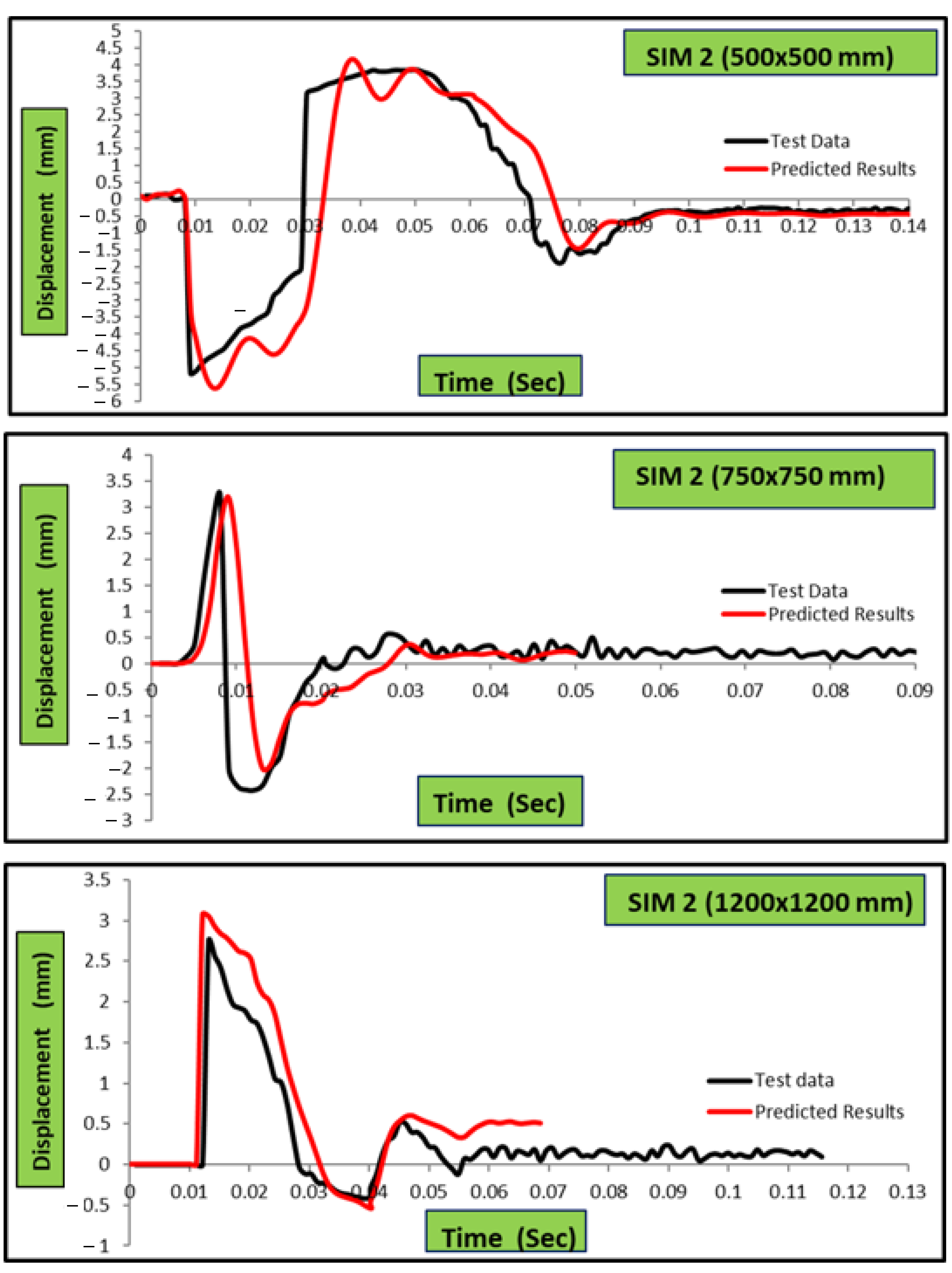
Figure 33, Figure 34 and Figure 35 reveal the effect of the strengthening type and thickness of SIMCON on the displacement of experimental tests and FE analysis of slabs over time. The numerically predicted ultimate axial deformations are less than the observed values, having an average experimental-to-numerical ratio of (1.024). This trend is connected to the decrease in slab stiffness caused by the slab’s expanding spread. It is also found that the displacement-time history is affected slightly by the thickness of SIMCON, but it is very clear when comparing the use of the strengthening type. A more efficient improvement of impact behavior is observed for the SIMCON strengthening type, causing the displacement values to decrease. The maximal displacement values of specimens strengthened with (20 and 30) mm SIMCON layers are 31% higher than those obtained from steel-strengthened specimens. Moreover, specimens that are full-scale strengthened (whether with steel or SIMCON) have greater efficiency than alternative sizes in terms of behavior improvement and maximal displacement reduction. In addition, the residual displacement values after vibration for the test specimen impact loading effect were found to be significantly less for 50 mm SIMCON or steel-strengthened specimens, in comparison with the reference test with no strengthening (Specimen 1). The values observed were about 178–133% higher than the residual displacement values of full-scale 20 and 30 mm SIMCON-strengthened specimens, respectively. However, they were found to be about 89% higher than the values obtained for full-scale strengthened specimens. The obtained results indicate that SIMCON strengthening has a successful effect on the impact behavior of RC slabs positively, resulting in the increase in maximal acceleration value and a significant decrease of maximal and residual displacement values. Similarly, the maximal residual displacement of SIMCON and steel plate strengthened test specimens was remarkably lower than the non-strengthened reference specimen. The interpretation is made that the use of SIMCON and steel plate strengthening limits the number and width of impact-induced cracks in an efficient manner.

4. Conclusions

This study aimed to develop various strengthening techniques against punching sheer or flexure that suit each of the used types of material. The efficiency of these strengthening techniques is investigated experimentally, as they were developed to enhance the behavior of NSC plates that are subjected to cyclic and impact loads. The plate strengthening is also investigated theoretically. The experimental results present significant data to verify the FE models and develop the analytical tools in the future to be used to strengthen concrete plates under cyclic and impact loads. Accordingly, the following conclusions were drawn:
(a)
The numerical results show that the plate thickness of SIMCON significantly affects the load-carrying capacity, and it increases along with the increase in thickness. Moreover, using strengthening from steel plates gives a higher load-carrying capacity.
(b)
The numerically obtained curves of the time history did not differ much from the experimentally obtained ones. Meanwhile, the numerically obtained maximal impact force was less than the experimentally obtained values. Regarding the reaction force, the time and deflection histories did not indicate any significant differences in shape.
(c)
The impact tests indicate the significance of the inertia forces. Based on the force-time history of the test, the impact force appears to undergo resistance throughout the inertial force of SIMCON plates initially. The forces that are created at the supports tend to increase in prominence during the post-impact stage, reaching their equilibrium. In addition, the measurements indicate great similarities in terms of reaction force, yet there are variations in terms of impact force and magnitude-to-mass times acceleration values.
(d)
The deflection of strengthened specimens is found to be less than the values obtained for the control specimens. The deflection rates between the strengthened control specimens in percentages are found to be between (43–57%) of the control specimens.
(e)
It has been observed that the increase in steel plate size results in an increase in the total slab stiffness. The essential parameter that influences the overall results of slab specimens strengthened with steel plates is the suitable location of the steel plates.
(f)
The stiffness of slabs strengthening with SIMCON is relatively higher than slabs strengthened with steel plates. Moreover, the axial load-displacement relation indicates that all the numerical models present a stiffer behavior than experimental axial load-displacement relations. The experimentally and numerically obtained results show how the slabs strengthened with 20 mm; SIMCON provided higher results than slabs strengthened with steel plates.
(g)
The strain gauges of SIMCON-strengthened slabs indicate that negative values were obtained at the bottom face strains during impact; meanwhile, the top surface strains obtained positive values. This could indicate that the slabs tend to show deflection upwards during impact, eventually causing compression on the bottom surface as opposed to the tension on top during the impact.
(h)
The strengthening technique used in the experiment led to a significant improvement in slab impact behavior. The ABAQUS FE analysis software is used for the verification of the obtained test results, whereby the specimens are simulated numerically. Despite the differences in results, it can be stated that numerically simulating the specimens has reduced the working load significantly, guiding the researchers with regard to the behavior of structural members under impact loading.
(i)
The SIMCON strengthening resulted in a considerable decrease in maximal slab displacement value due to impact. The crack width and quantity decreased significantly, especially lower for steel plate-strengthened slabs in all cases.
(j)
The increase in the area of SIMCON from 500 × 500 mm to 1200 × 1200 mm reduced the maximal displacement value of the test specimens. The results indicate that full-scale SIMCON-strengthened plates have remarkably lower damage rates under impact energy levels, withstanding higher impact energy values.
(k)
A significant reduction is found for SIMCON and steel plate-strengthened RC slabs. As for the residual displacement values, they represent the plastic deformation caused to the test specimens via impact loading.
(l)
Significant improvements have been observed in the impact behavior of slab specimens in light of the experimentally strengthened techniques used. Full-scale 30 mm SIMCON strengthening showed the highest performance.
(m)
The use of local, externally bonded steel and SIMCON plates to strengthen reinforced slabs against punching shear has proven the tensile face to be efficient.
(n)
As for the improvement of slab punching shear capacities, the bonding technique is found to be more efficient than the thickness of steel plates. Moreover, using SIMCON strengthening indicated a larger enhancement of punching shear strength than steel plates.
(o)
From the effect of strengthening type and thickness of SIMCON on the displacement of experimental tests and FE analysis of slabs over time, it is found that the numerically predicted ultimate axial deformations are lower than the observed values, having an average experimental-to-numerical ratio of (1.024). It is also found that the displacement-time history is affected slightly by the thickness of SIMCON, but it is very clear when comparing the use of the strengthening types.

Author Contributions

Conceptualisation, A.S.G.Q., M.H.Y. and M.M.K.; methodology, A.S.G.Q. and M.M.K.; validation, A.S.G.Q.; formal analysis, A.S.G.Q.; investigation, A.S.G.Q.; writing—original draft preparation, M.H.Y., M.M.K. and A.S.G.Q.; writing—review and editing, M.H.Y. and M.M.K.; supervision, M.H.Y. and M.M.K. All authors have read and agreed to the published version of the manuscript.

Funding

This research received no external funding.

Data Availability Statement

Data should be requested from the corresponding authors.

Conflicts of Interest

The authors declare no conflict of interest.

References

  1. Alexander, M.; Beushausen, H. Durability, service life prediction, and modelling for reinforced concrete structures–review and critique. Cem. Concr. Res. 2019, 122, 17–29. [Google Scholar] [CrossRef]
  2. Kadhim, A.; Sadique, M.; Al-Mufti, R.; Hashim, K. Long-term performance of novel high-calcium one-part alkali-activated cement developed from thermally activated lime kiln dust. J. Build. Eng. 2020, 32, 101766. [Google Scholar] [CrossRef]
  3. Kadhum, M.M.; M. Harbi, S.; S. Khamees, S.; Abdulraheem, M.S.; Farsangi, E.N. Punching shear behavior of flat slabs utilising reactive powder concrete with and without flexural reinforcement. Pract. Period. Struct. Des. Constr. 2021, 26, 04020060. [Google Scholar] [CrossRef]
  4. Shubbar, A.A.; Sadique, M.; Shanbara, H.K.; Hashim, K. The Development of a New Low Carbon Binder for Construction as an Alternative to Cement. In Advances in Sustainable Construction Materials and Geotechnical Engineering, 1st ed.; Springer: Berlin/Heidelberg, Germany, 2020; pp. 205–213. [Google Scholar]
  5. Shubbar, A.A.; Nasr, M.S.; Islam, G.M.S.; Al-Khafaji, Z.S.; Sadique, M.; Hashim, K.; Assi, L.N. Early Age and Long-term Mechanical Performance of Mortars Incorporating High-volume GGBS. In Proceedings of the Advances in Civil Engineering: Select Proceedings of ICACE, Singapore, 31st October 2022; pp. 267–274.
  6. Majdi, H.S.; Shubbar, A.; Nasr, M.S.; Al-Khafaji, Z.S.; Jafer, H.; Abdulredha, M.; Masoodi, Z.A.; Sadique, M.; Hashim, K. Experimental data on compressive strength and ultrasonic pulse velocity properties of sustainable mortar made with high content of GGBFS and CKD combinations. Data Brief 2020, 31, 105961–105972. [Google Scholar] [CrossRef] [PubMed]
  7. Shubbar, A.A.; Sadique, M.; Nasr, M.S.; Al-Khafaji, Z.S.; Hashim, K.S. The impact of grinding time on properties of cement mortar incorporated high volume waste paper sludge ash. Karbala Int. J. Mod. Sci. 2020, 6, 7. [Google Scholar] [CrossRef]
  8. Sulyman, M.; Haponiuk, J.; Formela, K. Utilization of recycled polyethylene terephthalate (PET) in engineering materials: A review. Int. J. Environ. Sci. Dev. 2016, 7, 100–108. [Google Scholar] [CrossRef]
  9. Moffatt, E.G.; Thomas, M.D. Durability of rapid-strength concrete produced with ettringite-based binders. ACI Mater. J. 2018, 115, 105–115. [Google Scholar] [CrossRef]
  10. Teng, K.H.; Kot, P.; Muradov, M.; Shaw, A.; Hashim, K.; Gkantou, M.; Al-Shamma’a, A. Embedded Smart Antenna for Non-Destructive Testing and Evaluation (NDT&E) of Moisture Content and Deterioration in Concrete. Sensors 2019, 19, 547–559. [Google Scholar]
  11. Lua, T.W.; Mendis, P.; Ngo, T.; Zhang, L.; Mohotti, D.; Sofi, M. Blast studies on bridges–A state-of-the-art review. Electron. J. Struct. Eng. 2014, 1, 7–19. [Google Scholar] [CrossRef]
  12. Malak, S.A.; Krstulovic-Opara, N. Micromechanical Tensile Behavior of Slurry Infiltrated Mat Concrete with Inclined Fibers. ACI Mater. J. 2019, 116, 69–80. [Google Scholar]
  13. Khamees, S.S.; Kadhum, M.M.; Alwash, N.A. Experimental and numerical investigation on the axial behavior of solid and hollow SIFCON columns. SN Appl. Sci. 2020, 2, 1094. [Google Scholar] [CrossRef]
  14. Zareei, S.A.; Ameri, F.; Bahrami, N.; Shoaei, P.; Musaeei, H.R.; Nurian, F. Green high strength concrete containing recycled waste ceramic aggregates and waste carpet fibers: Mechanical, durability, and microstructural properties. J. Build. Eng. 2019, 26, 100914. [Google Scholar] [CrossRef]
  15. Khamees, S.S.; Kadhum, M.M.; Alwash, N.A. Effect of hollow ratio and cross-section shape on the behavior of hollow SIFCON columns. J. King Saud Univ. -Eng. Sci. 2021, 33, 166–175. [Google Scholar] [CrossRef]
  16. Hashim, A.M.; Kadhum, M.M. Numerical and experimental study of postfire behavior of concentrically loaded SIFCON columns. ACI Struct. J. 2021, 118, 73–86. [Google Scholar]
  17. Khamees, S.S.; Kadhum, M.M.; Nameer, A.A. Effects of steel fibers geometry on the mechanical properties of SIFCON concrete. Civ. Eng. J. 2020, 6, 21–33. [Google Scholar] [CrossRef]
  18. Hackman, L.E.; Farrell, M.B.; Dunham, O.O. Slurry infiltrated mat concrete (SIMCON). Concr. Int. 1992, 14, 53–56. [Google Scholar]
  19. Krstulovic-Opara, N.; Malak, S. Tensile behavior of slurry infiltrated mat concrete (SIMCON). Mater. J. 1997, 94, 39–46. [Google Scholar]
  20. Yas, M.H.; Kadhum, M.M.; Al-Dhufairi, W.G. Development of an Engineered Slurry-Infiltrated Fibrous Concrete: Experimental and Modelling Approaches. Infrastructures 2023, 8, 19. [Google Scholar] [CrossRef]
  21. Subramani, T.; Senthilkumar, M. Finite element analysis of RC beams with externally bonded SIMCON laminates by using ANSYS. Int. J. Appl. Or Innov. Eng. Manag. (IJAIEM) 2016, 5, 148–155. [Google Scholar]
  22. Krstulovic-Opara, N.; Al-Shannag, M.J. Compressive Behavior of Slurry Infiltrated Mat Concrete (SIMCON). Mater. J. 1999, 96, 367–377. [Google Scholar]
  23. Gilani, A.M. Various Durability Aspects of Slurry Infiltrated Fiber Concrete. Ph.D. Thesis, Middle East Technical University, Ankara, Turkey, 2007. [Google Scholar]
  24. Mohsin, M.S.; Alwash, N.A.; Kadhum, M.M. Structural behavior of reinforced concrete beams with out of plane part. Case Stud. Constr. Mater. 2021, 15, e00767. [Google Scholar] [CrossRef]
  25. Krstulovic-Opara, N. SIMCON—A Novel High Performance Fiber-Mat Reinforced Cement Composite for Repair, Retrofit and New Construction. In Proceedings of the Materials for the New Millennium, New York, NY, USA, 10–14 November 1996; pp. 288–297. [Google Scholar]
  26. Ahmed, H.U.; Faraj, R.H.; Hilal, N.; Mohammed, A.A.; Sherwani, A.F.H. Use of recycled fibers in concrete composites: A systematic comprehensive review. Compos. Part B Eng. 2021, 215, 108769. [Google Scholar] [CrossRef]
  27. Balamuralikrishnan, R.; Jeyasehar, C.A. Experimental Investigation of RC Beams Retrofitted with Externally Bonded SIMCON Laminates. IUP J. Struct. Eng. 2009, 2, 32–46. [Google Scholar]
  28. Harris, D.K. Characterization of Punching Shear Capacity of Thin UHPC Plates. Ph.D. Thesis, Virginia Tech. University, Blacksburg, VA, USA, 2004. [Google Scholar]
  29. Elbakry, H.M.; Allam, S.M. Punching strengthening of two-way slabs using external steel plates. Alex. Eng. J. 2015, 54, 1207–1218. [Google Scholar] [CrossRef]
  30. Zhang, J.; Teng, J.; Wong, Y.; Lu, Z. Behavior of two-way RC slabs externally bonded with steel plate. J. Struct. Eng. 2001, 127, 390–397. [Google Scholar] [CrossRef]
  31. Sim, J.; Oh, H. Structural improvement of strengthened deck panels with externally bonded plates. Cem. Concr. Res. 2005, 35, 1420–1429. [Google Scholar] [CrossRef]
  32. Adhikary, S.D.; Li, B.; Fujikake, K. Residual resistance of impact-damaged reinforced concrete beams. Mag. Concr. Res. 2015, 67, 364–378. [Google Scholar] [CrossRef]
  33. Saatci, S.; Vecchio, F.J. Effects of shear mechanisms on impact behavior of reinforced concrete beams. ACI Struct. J. 2009, 106, 78–87. [Google Scholar]
  34. Batarlar, B. Behavior of Reinforced Concrete Slabs Subjeted to Impact Loads. Master’s Thesis, Izmir Institute of Technology, Gülbahçe, Turkey, 2013. [Google Scholar]
  35. Mohsin, M.S.; Alwash, N.A.; Kadhum, M.M. Comparative Study on Structural Behavior of Reinforced Concrete Straight Beam and Beams with out of Plane Parts. Int. J. Eng. 2021, 34, 2280–2293. [Google Scholar]
  36. Mahdi, Z.H.; Kadhum, M.M.; Abdulghani, M.R.; Abdulghani, G.R.; Hwaiai, D.A. Investigation about the Optimum Alternative of Polypropylene Fibers in Conventional Concrete. J. Eng. Sci. Technol. 2022, 17, 2658–2670. [Google Scholar]
  37. Sabar, A.H.A.; Kadhum, M.M. Strengthening of fire damaged, light weight, high strength reinforced concrete beam using SIFCON jacket. Period. Eng. Nat. Sci. 2022, 10, 587–606. [Google Scholar]
  38. Khalil, W.; Al-Daebal, T. Engineering Properties of Sustainable Self-Compacting Concrete With Clay Bricks Waste Aggregate. Kufa J. Eng. 2018, 9, 223–237. [Google Scholar] [CrossRef]
  39. Robertson, I.N.; Durrani, A.J. Gravity load effect on seismic behavior of interior slab-column connections. Struct. J. 1993, 89, 37–45. [Google Scholar]
  40. Marzouk, H.; Osman, M.; Hussein, A. Cyclic loading of high-strength lightweight concrete slabs. Struct. J. 2001, 98, 207–214. [Google Scholar]
  41. Ali, A.S.; Riyadh, Z. Experimental and Numerical Study on the Effects of Size and type of Steel Fibers on the (SIFCON) Concrete Specimens. Int. J. Appl. Eng. Res. 2018, 13, 1344–1353. [Google Scholar]
  42. American Concrete Institute (ACI). Specifications for Structural Concrete for Buildings; ACI: Farmington Hills, MI, USA, 2014. [Google Scholar]
  43. British Standards Institution (BSI). Code of Practice for Design and Construction: BS 8110; BSI: London, UK, 1985. [Google Scholar]
  44. Eurocode. Design of Concrete Structures—Part 1: General Rules and Rules for Buildings; Department of Communities and Local Government: London, UK, 2004. [Google Scholar]
  45. Simulia, D.S. Abaqus 6.14 CAE User Guide; Dassault Systèmes Simulia Corp.: Providence, RI, USA, 2015. [Google Scholar]
  46. Anil, Ö.; Durucan, C.; Erdem, R.T.; Yorgancilar, M.A. Experimental and numerical investigation of reinforced concrete beams with variable material properties under impact loading. Constr. Build. Mater. 2016, 125, 94–104. [Google Scholar] [CrossRef]
  47. Vamvatsikos, D.; Cornell, C.A. Incremental dynamic analysis. Earthq. Eng. Struct. Dyn. 2002, 31, 491–514. [Google Scholar] [CrossRef]
  48. Li, C.; Hao, H.; Bi, K. Numerical study on the seismic performance of precast segmental concrete columns under cyclic loading. Eng. Struct. 2017, 148, 373–386. [Google Scholar] [CrossRef]
  49. Birtel, V.; Mark, P. Parameterised finite element modelling of RC beam shear failure. In Proceedings of the ABAQUS Users’ Conference, Providence, RI, USA, 23–25 May 2006. [Google Scholar]
  50. Lubliner, J.; Oliver, J.; Oller, S.; Oñate, E. A plastic-damage model for concrete. Int. J. Solids Struct. 1989, 25, 299–326. [Google Scholar] [CrossRef]
  51. Lee, J.; Fenves, G.L. Plastic-damage model for cyclic loading of concrete structures. J. Eng. Mech. 1998, 124, 892–900. [Google Scholar] [CrossRef]
  52. Mander, J.B.; Priestley, M.J.; Park, R. Theoretical stress-strain model for confined concrete. J. Struct. Eng. 1988, 114, 1804–1826. [Google Scholar] [CrossRef]
  53. Wang, T.; Hsu, T.T. Non-linear finite element analysis of concrete structures using new constitutive models. Comput. Struct. 2001, 79, 2781–2791. [Google Scholar] [CrossRef]
  54. Malvar, L.J.; Ross, C.A. Review of strain rate effects for concrete in tension. ACI Mater. J. 1998, 95, 735–739. [Google Scholar]
  55. Fan, W.; Yuan, W.; Yang, Z.; Fan, Q. Dynamic demand of bridge structure subjected to vessel impact using simplified interaction model. J. Bridge Eng. 2011, 16, 117–126. [Google Scholar] [CrossRef]
  56. Do, T.V.; Pham, T.M.; Hao, H. Numerical investigation of the behavior of precast concrete segmental columns subjected to vehicle collision. Eng. Struct. 2018, 156, 375–393. [Google Scholar] [CrossRef]
  57. Sha, Y.; Hao, H. Laboratory tests and numerical simulations of barge impact on circular reinforced concrete piers. Eng. Struct. 2013, 46, 593–605. [Google Scholar] [CrossRef]
  58. Zangeneh Kamali, A. Shear Strength of Reinforced Concrete Beams Subjected to Blast Loading: Non-Linear Dynamic Analysis. Master’s Thesis, Royal Institute of Technology (KTH), Stockholm, Sweden, 2012. [Google Scholar]
  59. Demir, A.; Caglar, N.; Ozturk, H.; Sumer, Y. Non-linear finite element study on the improvement of shear capacity in reinforced concrete T-Section beams by an alternative diagonal shear reinforcement. Eng. Struct. 2016, 120, 158–165. [Google Scholar] [CrossRef]
  60. Zhu, H.; Stephens, M.T.; Roeder, C.W.; Lehman, D.E. Inelastic response prediction of CFST columns and connections subjected to lateral loading. J. Constr. Steel Res. 2017, 132, 130–140. [Google Scholar] [CrossRef]
  61. Obaidat, Y.T.; Heyden, S.; Dahlblom, O. The effect of CFRP and CFRP/concrete interface models when modelling retrofitted RC beams with FEM. Compos. Struct. 2010, 92, 1391–1398. [Google Scholar] [CrossRef]
  62. Hashim, A.M.; Kadhum, M.M. Compressive strength and elastic modulus of slurry infiltrated fiber concrete (SIFCON) at high temperature. Civ. Eng. J. 2020, 6, 265–275. [Google Scholar] [CrossRef]
  63. Abbas, A.S.; Kadhum, M.M. Impact of fire on mechanical properties of slurry infiltrated fiber concrete (SIFCON). Civ. Eng. J. 2020, 6, 12–23. [Google Scholar] [CrossRef]
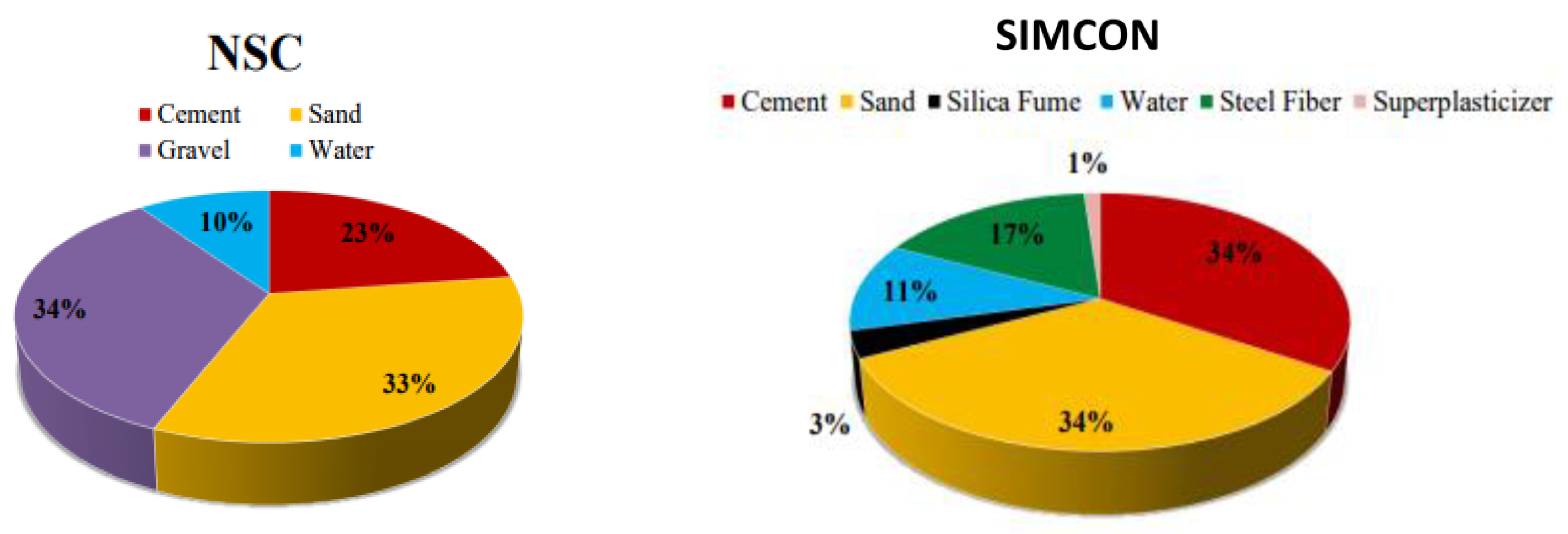
Figure 1. Material proportions adopted in NSC and SIMCON mixtures. (% of the total mix weight).
Infrastructures 08 00085 g001
Figure 2. Details of NSC slab reinforcement.
Infrastructures 08 00085 g002
Figure 3. Steel plate and bolt configurations (dimensions are in mm).
Infrastructures 08 00085 g003
Figure 4. Explanation of the plate specimen identification.
Infrastructures 08 00085 g004
Figure 5. Pouring the mix into the plywood mold for slab specimens.
Infrastructures 08 00085 g005
Figure 6. The curing process of slab specimens.
Infrastructures 08 00085 g006
Figure 7. Steel plate strengthening procedures (a) Plate roughening and drilling, (b) Steel plate with shear bolts.
Infrastructures 08 00085 g007
Figure 8. SIMCON laminates (a) fiber mats before coupling, (b) laminates after coupling to the slabs.
Infrastructures 08 00085 g008
Figure 9. Schematic diagram showing the supporting frame of plates.
Infrastructures 08 00085 g009
Figure 10. Instruments provided for testing, (A) LVDT of 50mm capacity, (B) Microscope for measuring the crack width, and (C) Data logger connecting to the computer to record data.
Infrastructures 08 00085 g010
Figure 11. Electro-hydraulic testing machine used for testing cyclic load of the plate.
Infrastructures 08 00085 g011
Figure 12. Drifting routine applied to the slabs under cyclic loadings.
Infrastructures 08 00085 g012
Figure 13. Set-up of the slab specimens.
Infrastructures 08 00085 g013
Figure 14. Detailed illustration of the slab testing set-up.
Infrastructures 08 00085 g014
Figure 15. The convergence study for the plate.
Infrastructures 08 00085 g015
Figure 16. The boundary conditions and finite element idealization of steel reinforcement of SIMCON and NSC slab specimens.
Infrastructures 08 00085 g016
Figure 17. Concrete to uniaxial loading in tensile (a) and compressive (b) responses.
Infrastructures 08 00085 g017
Figure 18. Bilinear traction-separation constitutive law.
Infrastructures 08 00085 g018
Figure 19. Load-central deflection curves.
Infrastructures 08 00085 g019
Figure 20. Stress of Center of Slab Versus Time Strengthened with 2 mm thick (500 × 500 mm) Steel Plate.
Infrastructures 08 00085 g020
Figure 21. Stress of at Center of Slab Versus Time Strengthened with 2 mm thick (750 × 750 mm) Steel Plate.
Infrastructures 08 00085 g021
Figure 22. Stress versus time at the slab center strengthened with 2 mm (1200 × 1200 mm) steel plate.
Infrastructures 08 00085 g022
Figure 23. Load-strain curves.
Infrastructures 08 00085 g023
Figure 24. Experimental and numerical load-axial displacement relationship of slabs with steel plates for different cross-sections.
Infrastructures 08 00085 g024aInfrastructures 08 00085 g024b
Figure 25. Experimental and numerical load-axial displacement relationship of slabs with SIMCON (thickness 20 mm, different cross-sections).
Infrastructures 08 00085 g025
Figure 26. Experimental and numerical load-axial displacement relationship of slabs with SIMCON (thickness 30 mm, different cross-sections).
Infrastructures 08 00085 g026
Figure 27. Variation of axial displacement (U) and plastic strain (PEMAG) for slabs cyclic load.
Infrastructures 08 00085 g027
Figure 28. Crack pattern distribution for slab strengthening under cyclic load (Steel plate = 500 × 500 mm).
Infrastructures 08 00085 g028
Figure 29. Crack pattern distribution for slab strengthening under cyclic load (Steel plate = 750 × 750 mm).
Infrastructures 08 00085 g029
Figure 30. Crack pattern distribution for slab strengthening under cyclic load (SIMCON thickness = 30 mm, cross-section 500 × 500 mm).
Infrastructures 08 00085 g030
Figure 31. Crack pattern distribution for slab strengthening under cyclic load (SIMCON thickness = 30 mm, cross-section (750 × 750 mm).
Infrastructures 08 00085 g031
Figure 32. Crack pattern distribution for slab strengthening under cyclic load (SIMCON thickness = 30 mm, cross-section 1200 × 1200 mm).
Infrastructures 08 00085 g032
Figure 33. The comparison between the displacement of experimental tests and FE analysis of slabs strengthened with steel plates of different cross-sections.
Infrastructures 08 00085 g033
Figure 34. Comparing the ultimate load of experimental tests and FE analysis of slabs strengthened with SIMCON (thickness 20 mm and different cross-sections).
Infrastructures 08 00085 g034
Figure 35. The comparison between the ultimate load of experimental tests and FE analysis of slabs strengthened with SIMCON (thickness 30 mm, different cross-sections).
Infrastructures 08 00085 g035
Table 1. Summary of tested plate specimens.
Summary of SpecimensType of Loading
CyclicImpact
TypeDimensions500 × 500750 × 7501200 × 1200500 × 500750 × 7501200 × 1200
Steel2 mmPC-St2-1PC-St2-2PC-St2-3PI-St2-1PI -St2-2PI -St2-3
4 mmPC-St4-1PC-St4-1PC-St4-1PI -St4-1PI -St4-1PI -St4-1
SIMCON20 mmPC-SIM20-1PC-SIM20-2PC-SIM20-3PI -SIM20-1PI -SIM20-2PI -SIM20-3
30 mmPC-SIM30-1PC-SIM30-2PC-SIM30-3PI -SIM30-1PI -SIM30-2PI -SIM30-3
Control PC-N0-0PI-N0-0
Table 2. Properties of concrete, steel reinforcement, steel hammer, and steel loading plate.
Concrete
Elastic modulus23,500 Mpa
Compressive strength 25 Mpa
Tensile stress3.12 Mpa
Poisson’s ratio0.2
ψ30
e0.1
σ b0/ σ c01.16
Kc0.6667
μ 0.0001
Steel reinforcement
Elastic modulus200,000 Mpa
Poisson’s ratio0.3
Yield stress425 Mpa
Steel hammer-steel loading plate
Elastic modulus200,000 Mpa
Poisson’s ratio0.3
Table 3. Cohesive zone model parameters.
ParameterValue
K0640 Mpa
τ max3 Mpa
Gcr900 J/m2
τ s 0 = τ t 0 1.5 Mpa
G n c 90 J/m2
G t c 900 J/m2
G s c 900 J/m2
n 1.45
Table 4. Central deflection values at P = 158 kN.
ParameterSpecimen
PC-N0-0 = 6.35PC-St2-1 = 3.87PC-St-1 = 3.26PC-SIM-20-1 = 2.94PC-SIM-30-1 = 2.86
Test deflection (mm)7.243.913.423.222.87
Normalized deflection (mm)7.823.913.423.222.87
Table 5. Comparison of peak load and increase ratio for control and test slabs.
SlabLoad (kN)Increase Ratio (%)
PC-N0-0160-
PC-St2-119018.75
PC-St4-120025
PC-SIM20-120025
PC-SIM30-122037.5
Disclaimer/Publisher’s Note: The statements, opinions and data contained in all publications are solely those of the individual author(s) and contributor(s) and not of MDPI and/or the editor(s). MDPI and/or the editor(s) disclaim responsibility for any injury to people or property resulting from any ideas, methods, instructions or products referred to in the content.