1. Introduction
The large number of existing buildings in Italy without adequate seismic protection [
1] requires the definition of sustainable intervention techniques that are able to reduce time and costs, and limit interruptions to use. Recent earthquakes demonstrated the significant losses that may be incurred when buildings miss seismic requirements [
2]. At the same time, these buildings show unsatisfactory energy performance mainly due to their heating and cooling needs, but also to lighting and domestic hot water supply. In fact, it is estimated that European buildings’ energy consumption is about 40% of the total energy demand [
3,
4]. The current energy crisis due to the large price increase for natural gas [
5] necessitates investment in energy efficiency of both residential and non-residential buildings, as well as diversification of natural gas supplies to reduce the dependence on a single supplier country [
6].
Specifically, regarding the seismic performance of existing reinforced concrete (RC) structures, most of the gap is due to inadequate detailing and poor behaviour of fragile elements like beam-column joints (e.g., Refs. [
7,
8]) as well as poor materials, as clearly demonstrated by recent earthquakes [
9,
10]. In the meantime, advanced methods to assess [
11] and monitor the structural integrity of critical components in RC buildings have been developed and are available for the full understanding of their behaviour and to evaluate the best retrofit strategies. Moreover, old envelope solutions and outdated mechanical and electrical systems lead to high energy consumption, which is currently not sustainable from both the environmental and economic points of view [
4,
12].
In the last decade, the trend to treat seismic strengthening and energy efficiency improvement as two different problems has been turned into a more consistent approach based on the combination or integration of structural and energy measures to guarantee the minimisation of intrusiveness and invasiveness of renovation actions [
13]. In fact, it is even more important to reduce as much as possible the losses due to seismic damage after an energy efficiency intervention is carried out. Usually, the combination of seismic and energy interventions requires only compatibility of the different measures, while the integration is normally obtained when a single engineered system provides both the effects of seismic and energy upgrading, and the compatibility is guaranteed [
14].
Therefore, at both the Italian and European levels, sustainable seismic strengthening techniques were and are being developed, at both local and global levels, within the activities of several research projects. As an example, Work Package 5 “Integrated and Sustainable Interventions for the Requalification of Existing Buildings”, carried out in the framework of the 2019-21 and the 2022–2024 research programs funded by the Italian Dept. of Civil Protection (DPC) and conducted by the Network of Laboratories of Earthquake Engineering (ReLUIS), aimed at developing and applying in a sustainable way seismic strengthening solutions. Results of this project are represented by design methodologies for the integrated structural and energy retrofit of existing RC buildings [
15], in which patented global [
16] and local [
17] seismic strengthening systems were conceived in order to allow cheap interventions only from the outside. Global techniques are mainly represented by exoskeletons, which can have a reinforced concrete or steel structure [
18], and can function as an additional moment-resisting frame applied to the existing structure or as a dissipative structure provided with purposely designed hysteretic devices [
19]. Wide research was also devoted to setting new design methods accounting for the vulnerability of the existing structure and the limit states design objectives [
20]. Integrated intervention techniques have also been studied in the framework of the European research program “REEBUILD: Integrated techniques for the seismic strengthening and energy efficiency of existing buildings”. In fact, Ref. [
21] reports a wide literature review regarding intervention techniques able to provide seismic and energy measures in an integrated manner. As an example, integrated interventions can be grouped in three main categories: integrated exoskeleton solutions, interventions on the envelope and interventions on the horizontal members. Each one of these categories can be exploded into several specific techniques that have already been applied or at least laboratory tested to an intermediate TRL (Technology Readiness Level). Other studies [
22] outlined the possibility of using retrofit systems for existing reinforced concrete buildings consisting of precast concrete panels, which are able to improve both the structural and energetic performance.
This research describes the seismic and energy upgrading of an RC school building built in the 1960s using a seismic upgrading strategy based on a newly conceived dissipative exoskeleton [
23], which was considered for integration with high-performance external insulation finishing systems (EIFS) adopting low-thickness panels [
24].
The strengthening solution, named HPDF (high performing dissipation frame), is based on RC frames connected to the existing structure to provide it with additional seismic capacity, also through dissipative properties imparted by purposely designed steel elements placed at the beams’ mid-span.
In between the new and the existing frame, thermal insulation panels are inserted to increase energy efficiency. Other energy measures are also foreseen, for example, the replacement of the heating system, lighting system and roof insulation.
In the following,
Section 2 describes the case study building as well as the seismic and energy efficiency assessment;
Section 3 provides a detailed description of the intervention concept (seismic strengthening and energy improvement) along with the adopted procedures for design purposes; and finally,
Section 4 reports the results and discussion based on calculated savings due to the utilised techniques with a comparison of the pre- and post-intervention conditions.
2. Materials and Methods
2.1. Case Study Building
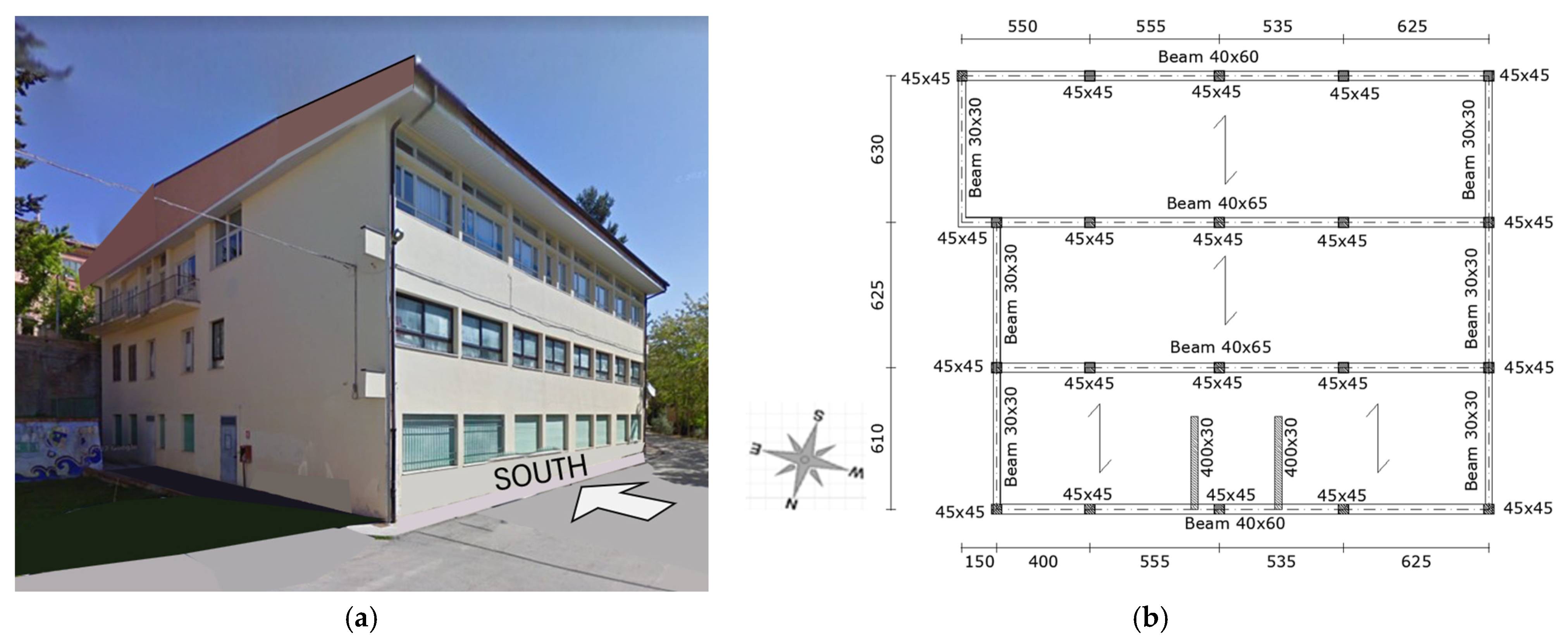
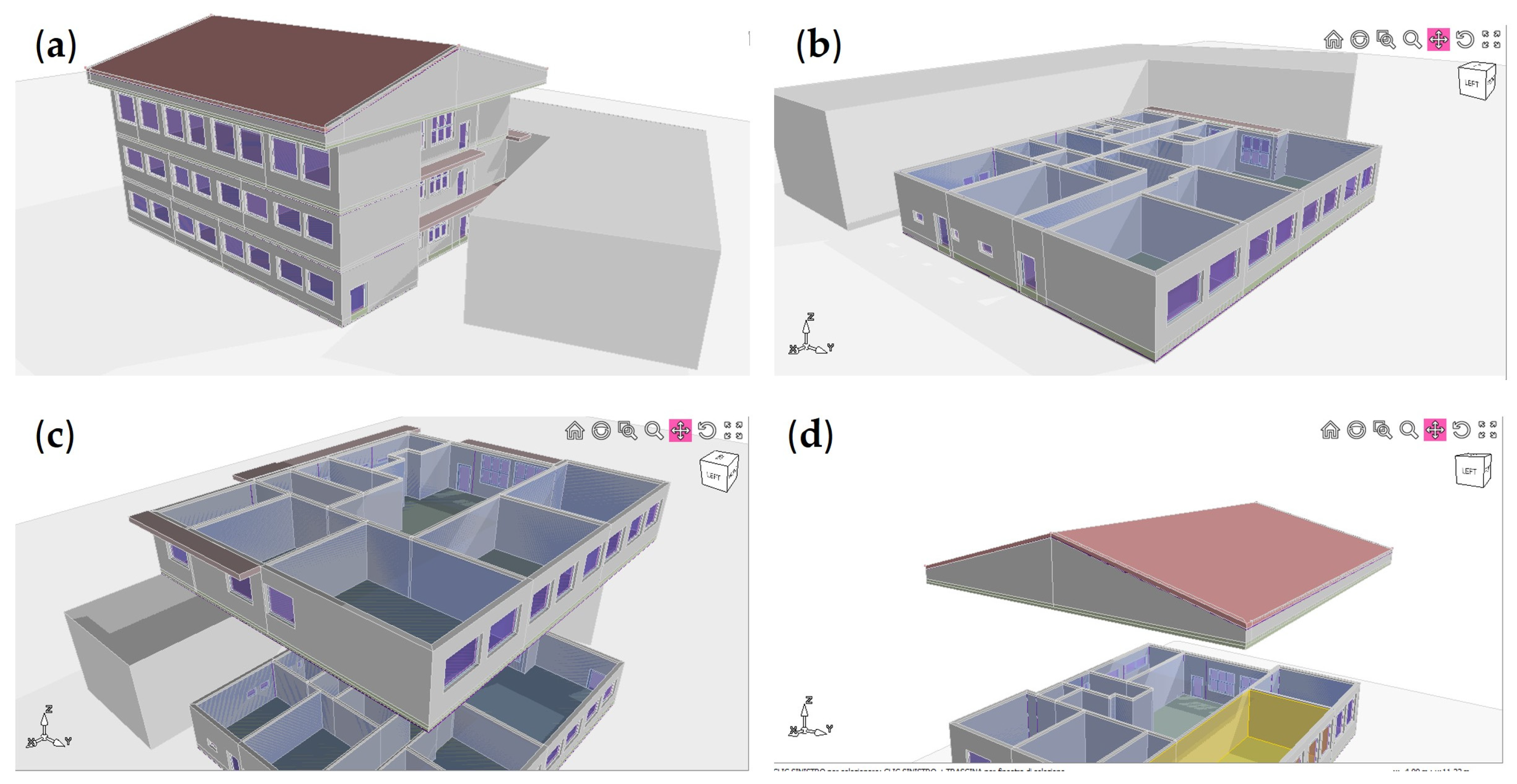
In order to realise an integrated seismic upgrading intervention using the HPDF technique, working only from the outside and coupled with an energy efficiency renovation, a primary school building (
Figure 1a) located in the province of Macerata (Italy) was considered. The seismic strengthening intervention on this building was already illustrated in previous research [
25], showing the general design choices without specific details about the seismic–energy integration of measures. Therefore, the main aim of this study is to illustrate the details of seismic–energy integration. The selected building dates back to the 1960s, and was designed only in reference to gravity loads. It was affected by the 2016–2017 central Italy seismic sequence that caused some structural and non-structural damage to many other school buildings in the area [
26]. The school building has an RC frame structure, with an almost square plan (with a floor area of about 400 m
2 and a total volume of about 3600 m
3) and three stories (
Figure 1a), visible from the south side, while only one storey can be seen from the north side where a retaining wall is present. The total building height is 12 m, including a low-rise attic. The frame is made of a regular mesh of columns arranged through a series of one-way frames (
Figure 1b). The staircase is made of two RC walls and is placed eccentrically with respect to the building’s centre of mass.
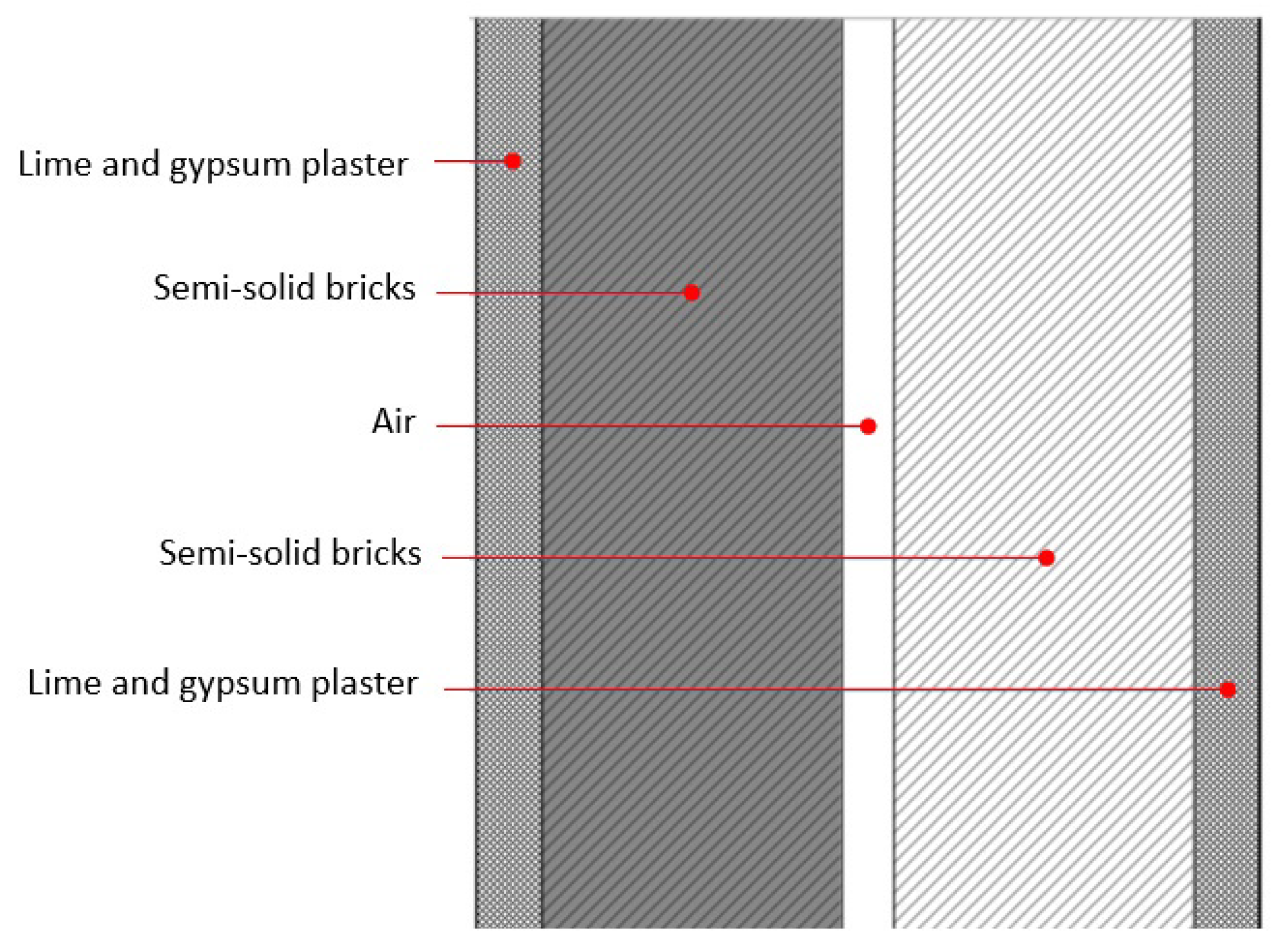
As with most of the existing Italian buildings built before the enforcement of the first energy saving law [
27], the envelope of the building at hand is provided with low thermal resistance, imposing high energy demands for heating and cooling the classrooms. In fact, the vertical infill walls (with a total thickness of 300 mm) are made of two 115 mm thick layers of semi-solid bricks with a 20 mm air gap, resulting in a total thermal transmittance (i.e., U-value) equal to 1.031 W/m
2K (
Figure 2). The intermediate floor slabs are made up of mixed brick-reinforced concrete joists (240 mm thick) complemented by a lightweight concrete creed and stoneware tiles (leading to the total thickness to 300 mm) with a total U-value of 1.353 W/m
2K. The roof slab is made up of 160 mm thick brick elements with a 40 mm concrete plate completed by two plaster layers (internal and external) 20 mm thick with a total U-value equal to 1.149 W/m
2K. The windows are made of two 4 mm glass layers with an air gap of 12 mm, which have a U-value equal to 2.849 W/m
2K.
The winter air conditioning system is made of cast iron radiators as emission terminals, with a fluid delivery temperature equal to 75 °C and the return temperature equal to 65 °C. The generator is a standard-type natural gas boiler with a thermal power of 115 kW. The DHW production system is made of an additional natural gas boiler with a thermal power of 32 kW. There is no summer air conditioning, nor any mechanical ventilation (VMC) and renewable energy production inside the building.
In order to characterise the energy demand, the school is located in climatic zone E, with 2150 heating degree days (HDDs).
2.2. Seismic Assessment
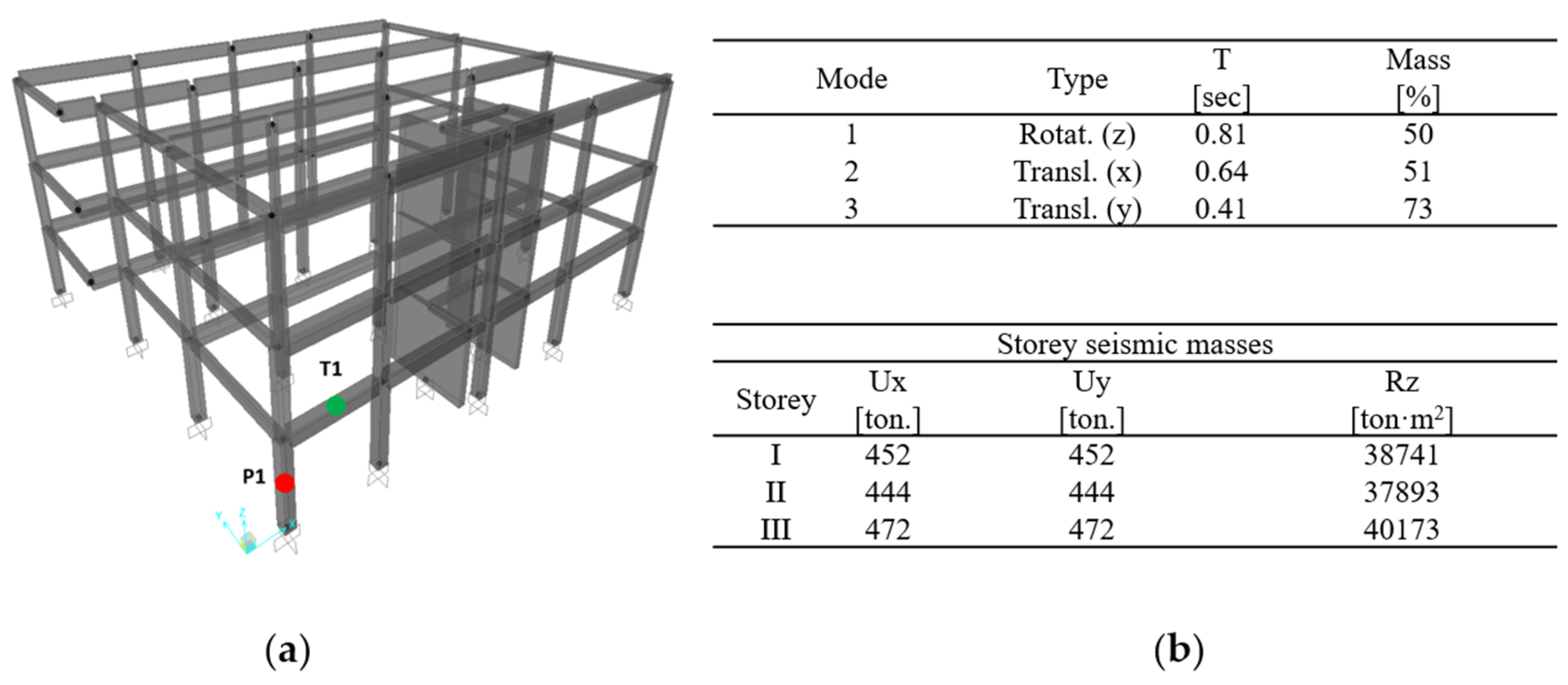
In order to apply the selected seismic strengthening technique, the as-built condition of the building at hand had to be assessed. To this purpose, a FEM model (
Figure 3) of the building structure was constructed using SAP2000 software [
28] to perform push-over analyses based on the lumped plasticity assumption (
Figure 4). Therefore, the material properties were assessed through the available results of a destructive and non-destructive tests campaign according to the Italian code [
29]. In fact, the mean value of the concrete compressive strength was derived from compressive tests on cores extracted from the structure, resulting in a value equal to f
cm = 10.9 MPa. The yielding stress of the reinforcing steel was obtained from tensile tests on rebars belonging to the structure, resulting in a mean value equal to f
ym = 370 MPa. Based on the above reported material properties, the moment–rotation relationships were calculated, which accounted for the reinforcement amount of each single structural member. The reinforcement arrangement and moment–rotation relationships of typical column and beam members are reported in
Figure 4a–d, respectively. As can be seen from the tables in
Figure 3b, the first mode shape involves rotational effects due to the eccentric position of the staircase. This latter influences the seismic response of the building.
The column cross-sectional dimensions are generally 45
× 45 cm (
Figure 4a), while beams have a 40 × 65 cm section, as shown in
Figure 4b (column P1 and beam T1 in
Figure 3a).
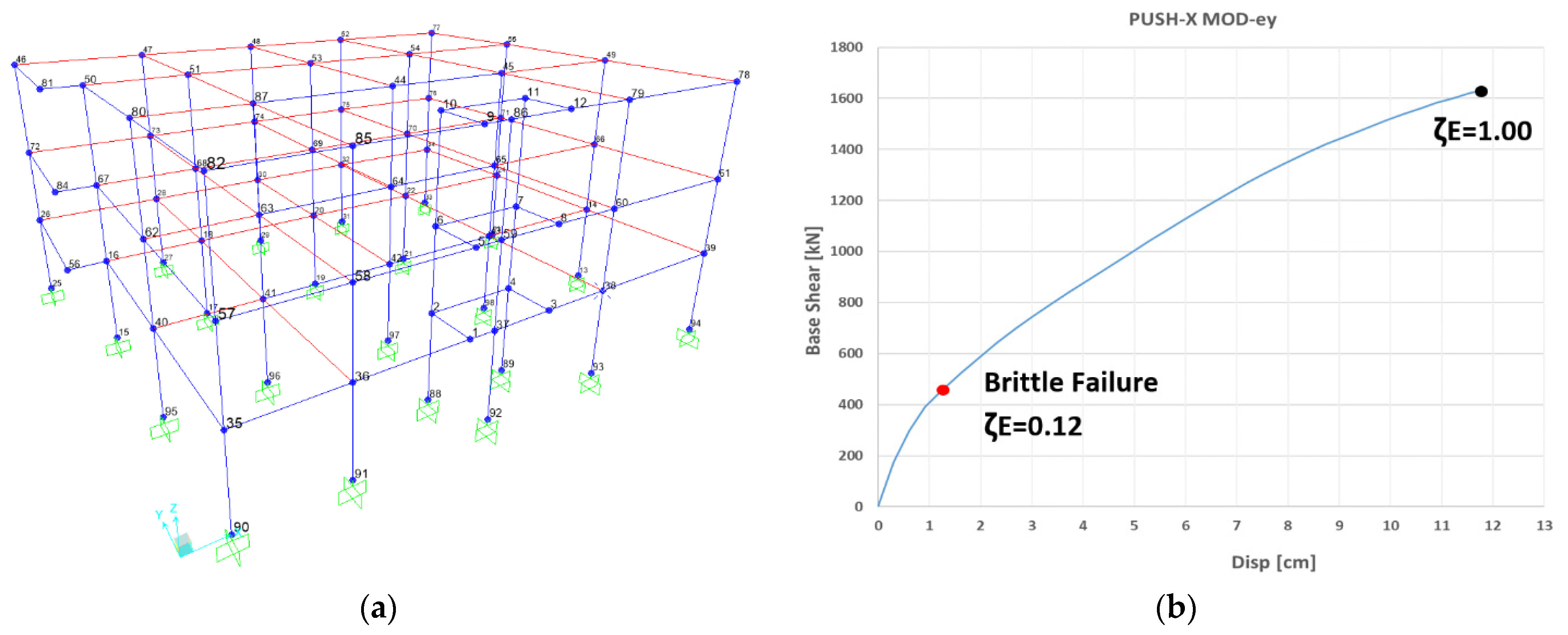
The structure’s capacity curve in the X-direction (
Figure 5b) was obtained via the push-over analysis considering a load distribution corresponding to the trend of the storey forces calculated through linear dynamic analysis, including in each direction a number of modes with a total participating mass equal to at least 85%. It is worth noting that the staircase walls were modelled as 1D elements. This was possible due to the fact that a similar stiffness is provided by frame elements, and when performing the shear safety checks, suitable shear capacity models were adopted.
The analysis was arrested at a roof displacement of 120 mm, corresponding to the condition of the seismic capacity–demand ratio equal to ζE = 1. This behaviour does not account for any possible brittle failure. In fact, only ductile failures are considered and occur when the rotation capacity of an RC member is exceeded.
The identification of the life safety (LS) limit state achievement can be carried out according to several assumptions. The study reported in [
30] provided an overview of the ways that are available to identify this condition. In some cases, it can be assumed that the limit state is reached when a significant percentage (e.g., 50%) of members reach certain conditions (for example, 75% of the ultimate chord rotation for flexure or the shear failure). This study assumed that the LS limit state is reached when the first element achieves a chord rotation equal to 75% of the ultimate value or the failure in shear. Even though this is significantly conservative, this criterion fully matches the Italian building code. Therefore, it is consistent with the usual practitioners’ approach.
Therefore, the detection of shear failures was carried out by manually comparing shear stresses and capacity values step-by-step in a post-processing phase. In this way, it was possible to find the top displacement for which the first fragile crisis happened (and the corresponding base shear value) that was equal to d = 11 mm. The seismic safety index is expressed in terms of the capacity–demand ratio, which, at this displacement level, is ζE = 0.12, representing the life safety limit state condition.
2.3. Energy Efficiency Assessment
The energy assessment was carried out in the framework of the monthly quasi-steady state approach. The useful floor and the volume of the building are Su = 1202.57 m2 and V = 5121.70 m3, respectively, while the surface-to-volume ratio S/V = 0.28, with S being the total external surface. The building location is in climate zone E, with 2150 heating degree days (HDD).
The simplified monthly quasi-steady state method is based on the European Standard ISO 13790 [
31] and the UNI 11300 [
32], calculating the seasonal energy balance of the building that includes all energy sources and sinks, as well as all energy flows through its envelope. As an example, in the energy balance for heating, transmission losses through external surfaces and ventilation losses caused by natural or mechanical exchange of warm indoor air with colder outdoor air through joints, are compared with the energy gains due to the irradiation of solar energy through the building envelope and to internal gains generated by the heat released by persons, appliances, computers and other electric devices, as well as from illumination. Finally, the energy needed to maintain the desired room temperature using heating systems is calculated as the excess of the losses compared to the gains. Renewable energy technologies represent one of the possible solutions to achieve a remarkable reduction in energy need, especially in colder climate zones.
Calculations were carried out using the TERMOLOG “Accademy” V14 software,(
Figure 6), according to the type of vertical closure elements and floors (as described before), the presence of thermal bridges and the type of existing thermal system.
Figure 6a shows how the presence of the retaining wall was considered in order to account for the correct amount of solar radiation.
In addition to the enclosure walls’ properties, detailed information about the heating and lighting systems was accounted for, as well as the presence of partitions and windows.
A further important aspect is related to thermal bridges, which were defined for each singular point of the building and characterised via specific FEM analysis. Thermal bridges can contribute to increasing the energy demand during heating and cooling seasons, producing condensation problems. In thermal bridges, the thermal resistance is modified by penetration of the building envelope via materials with different thermal conductivities, with a change in thickness or with a difference between internal and external areas.
Thermal barriers can reduce heat transmission losses and on the basis of a 2D finite element numerical model (FEM), the effects of thermal insulation have been numerically investigated.
The cases examined concern thermal bridges between the following elements:
Vertical walls and floors (attic, inter-floor and balcony);
Façade columns and infills;
Corner columns and infills;
Partitions and infills;
Ground and foundations.
As an example,
Figure 7 shows the FEM model of the thermal bridge between a corner column and the two adjacent infill walls.
The energy needs are assessed, assuming an internal temperature of the heated rooms equal to 20 °C, also considering for the unheated attic a correction coefficient equal to 0.9 (pursuant to UNI-TS 11300 [
32]). It should be noted that the building is located in climatic zone E; therefore, the heating systems are switched on from 15 October to 15 April. As a result of the energy efficiency assessment in the as-built condition, the global non-renewable energy performance index is EPgl, with nren = 189.60 kWh/m
2 year, which corresponds to the total energy consumed by the air-conditioned building per unit of surface (in one year).
3. Integrated Seismic–Energy Upgrading Intervention
3.1. Design Philosophy
The renovation of public buildings increasingly deals with older constructions with very poor material quality, improper organisation of interior space and inefficient systems, resulting in unhealthy climate and air quality. The sum of the overall inadequacies of these buildings often leads to the design of invasive interventions that require long-lasting maintenance or, in extreme cases, demolition and reconstruction, which have a great impact on activities performed in public buildings like schools and hospitals, and impair the sustainability of such an approach.
Indeed, sustainability is commonly represented by the three-pillar conception based on social, economic and environmental requirements, which must all be considered together [
33]. This broad meaning of the sustainability concept needs to be translated into the building industry through more specific and technical concepts.
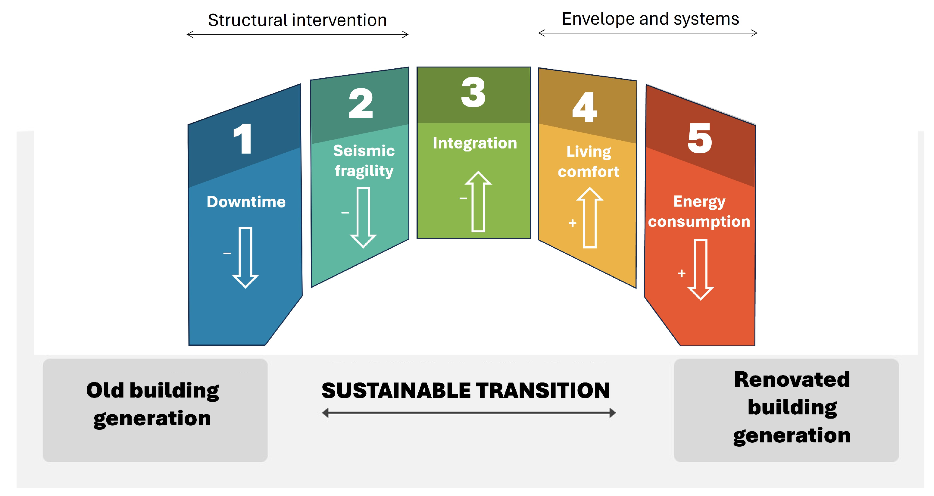
Therefore, the design of renovation interventions on public buildings should be based on the following five stones that are able to act together, providing a sustainable transition to the new generation buildings (
Figure 8):
Lowering downtime: this allows the building to be used as long as possible during the intervention work. This avoids building managers having to relocate activities and find substitute buildings, as well as the users having to change location.
Reducing seismic fragility: structural interventions devoted to reducing the seismic vulnerability of buildings are able to strongly reduce the damage in case of a seismic event. This allows for rapid recovery of the building’s functionality, without any interventions or through cheap repair work. The direct and indirect losses for the community are significantly lowered and, as a result, the resilience is highly improved.
Providing integration: any intervention technique or a combination should be able to cover all of the aspects, from 1 to 5, to be sustainable and rewarding with respect to the community’s needs.
Increasing the users’ living comfort: during the COVID-19 pandemic, heavy disruptions were experienced in the education sector. For many months, students were not allowed to attend lessons in person, forcing them to receive distance education, which involves many drawbacks such as a lack of socialisation. To this end, for example, a mechanical ventilation system is highly effective in improving the air quality inside buildings, thus permitting their use safely.
Reducing energy consumption: improving the energy efficiency of buildings is a mandatory task to be performed when dealing with renovation interventions, in order to reduce the carbon footprint of housing and increase the economic sustainability of the administrative bodies.
Considering a “three-pillar” perspective, stones 1 and 4 could be assumed to belong to the social pillar, stone 2 belongs to all three pillars, since lowering the seismic fragility impacts on damage (economic), reduces the building unavailability due to repair work (social) and decreases the need for raw materials for repair work (environmental). Stone 5 is mainly related to the economic and environmental pillars due to lower energy consumption and carbon footprint, respectively. As a result, integration is the key stone, which allows the others to remain together, and therefore pertains to all three pillars. The integration requirement is related to designing all aspects of a renovation so that they can be easily combined without interference, or are even provided by one engineered solution able to cover the structural and energy aspects together.
3.2. Intervention Overview
In this section, the main idea of the renovation intervention is described in reference to the integration of the seismic strengthening intervention and the installation of the external insulation finishing system devoted to reducing the thermal transmittance of the building envelope.
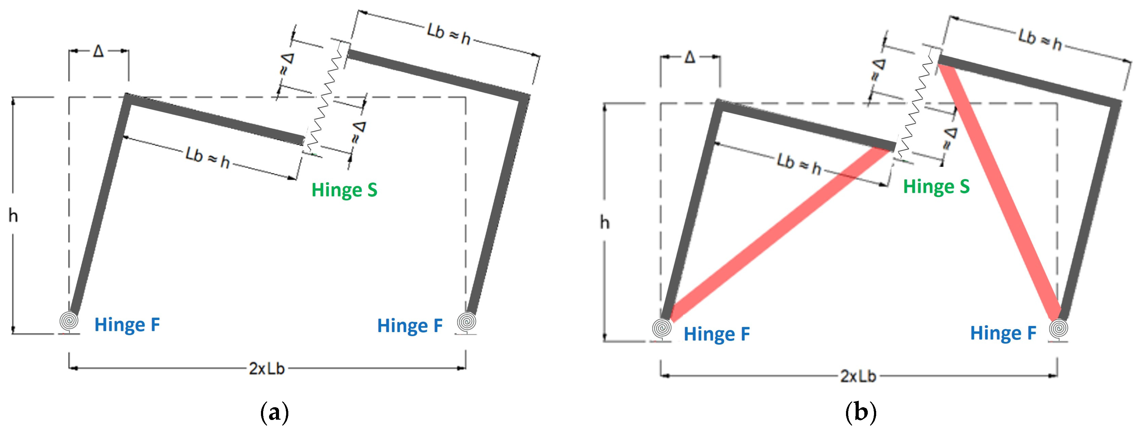
Figure 9a shows how the HPDF system includes two main components, a column and a half beam. The system is conceived to function through two dissipative components. The first is a shear hinge (S hinges) placed at the beam end, working under the relative displacements between the two beam ends. The second dissipation source is made up of a flexural hinge (F hinge) placed at the base of the column, working under the rotation of column members with respect to the foundation. It can easily be determined that if the span length is two times the inter-storey height, the S hinge experiences a relative displacement that is double the inter-storey drift. This is a clear advantage in comparison to devices working under the inter-storey drift, such as for bracing systems.
The HPDF system’s effectiveness increases when the framing elements’ stiffness increases. To maximise the relative displacement of the S hinges, small or negligible deformations of the beams are required. This aspect is significantly related to the span length of beams, and could limit the applicability of the HPDF in some cases (large spans). In order to avoid using large cross-sections of beams and columns, additional braces can be used to increase the efficiency of the system (
Figure 9b).
The new frames of the HPDF system must be connected to the existing structure using shear connectors grouted with epoxy resin and designed to resist the (inertial) shear forces that are transferred from the existing structure to the new frames. In order to allow for dissipative kinematics, the connections must be such that only vertical displacements are allowed.
The connection between the HPDF system and the existing structure must be present only at beam–column joints, in order to allow a rigid body behaviour of the new frames with respect to the existing ones. For the building at hand, the arrangement of
Figure 9b was used due to the presence of large spans in the framed structure that forced the adoption of measures to reduce the exoskeleton deformability.
Figure 10 shows the FEM model in SAP2000, provided with exoskeleton RC members (in red), bracing steel elements (in blue) and existing RC members (in grey).
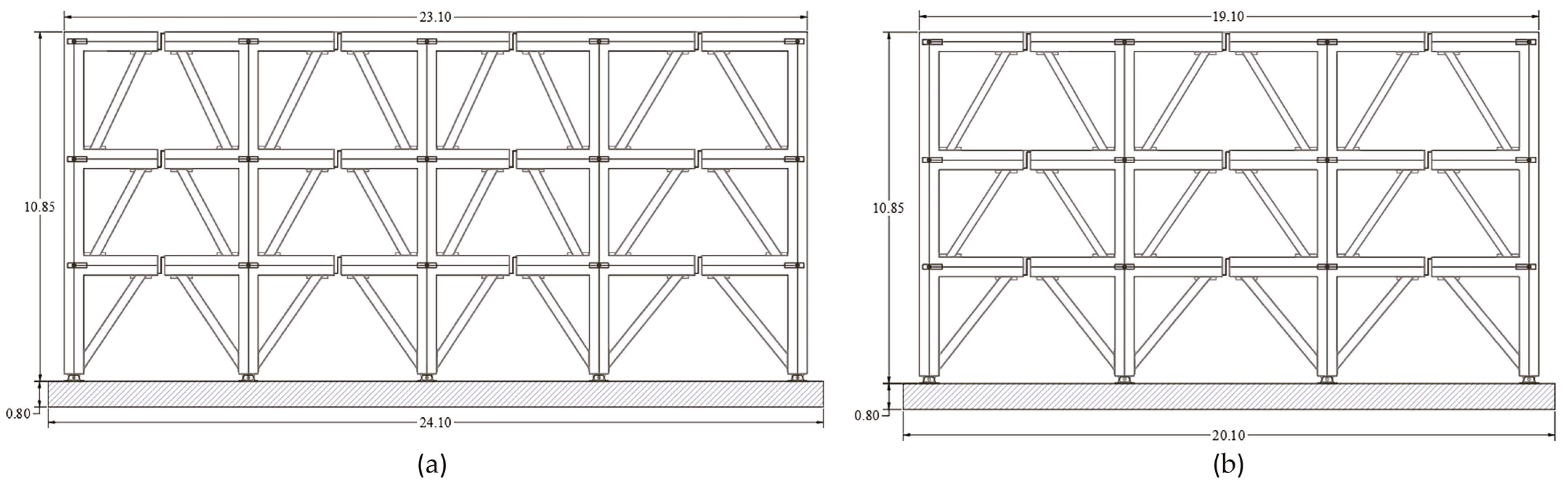
As can be seen from
Figure 11, the exoskeleton frames are made of beams and columns with 40 × 60 cm cross-sections, assuming a concrete grade of C28/35 according to Eurocode 2 [
34]. The columns are hinged at the base so that the F hinges do not have any stiffness and strength. At the mid-spans, the beams are interrupted to allow the presence of S hinges, which must provide the needed stiffness and strength.
As the main novelty proposed in this concept technique, at each beam-column joint location the exoskeleton and the existing frame are connected through a purposely developed steel connection that allows for the integration with the thermal insulation intervention. In more traditional exoskeleton solutions, new frame elements are rigidly connected to the existing structure along the entire length of each element, as, for example, in the case of non-dissipative solutions [
16]. On the contrary, exoskeletons based on the HPDF solution must be connected only in beam-column joints through a device that is able to allow for relative rotation between the existing and new members (according to
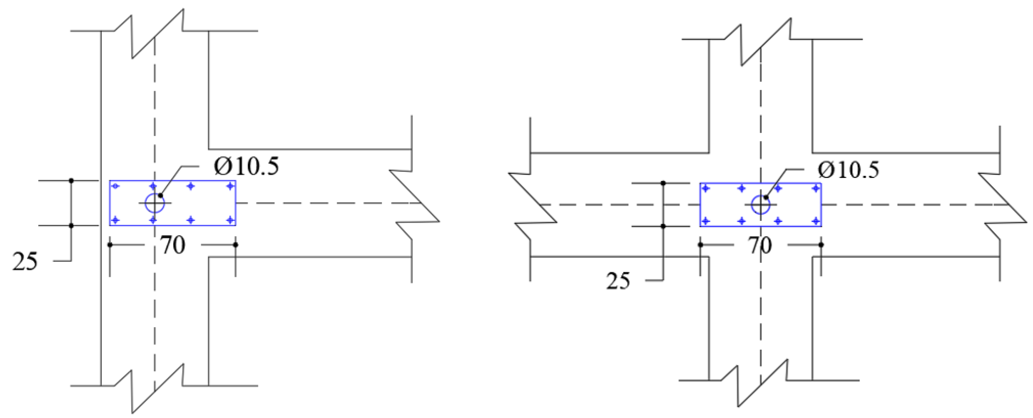
Figure 12). Moreover, the existing and new elements must be separated by a gap that permits the installation of insulation material. For this reason, the connection (named “gap connection”) is conceived specifically to fulfil these two requirements assuming the shape of a pin connection with an 8 cm gap between the existing and new RC members (
Figure 12). The gap connection is made up of two main steel plates (
Figure 13) that are anchored to both of the concrete structures through bolted rods.
These two plates are connected by a steel cylinder that assures pin restraint between the existing and new structure, permitting free relative rotation. The gap dimension (distance between the old and new structure) is equal to 80 mm (
Figure 14). Out of these 80 mm, 50 mm are used to accommodate the presence of insulation panels, and 30 mm are necessary for the presence of the exoskeleton’s formworks (during construction) and to easily remove them after concrete curing. Therefore, the working phases for the seismic–energy intervention are as follows:
Installation of gap connections at each beam-column connection;
Preparation of the insulation panels with notches to house the gap connections;
Installation of the external insulation finishing system, painting included;
Realisation of the exoskeleton.
3.3. Seismic Upgrading Design
Seismic upgrading is designed to achieve a capacity–demand ratio equal to at least ζ
E= 0.6, which corresponds to the minimum threshold required for Italian strategic buildings and schools. The detailed design procedure is shown in [
23], and it is briefly recalled here.
First of all, the nonlinear static (pushover) analyses have to be carried out on the as-built model of the existing structure using a suitable load pattern (e.g., Ref. [
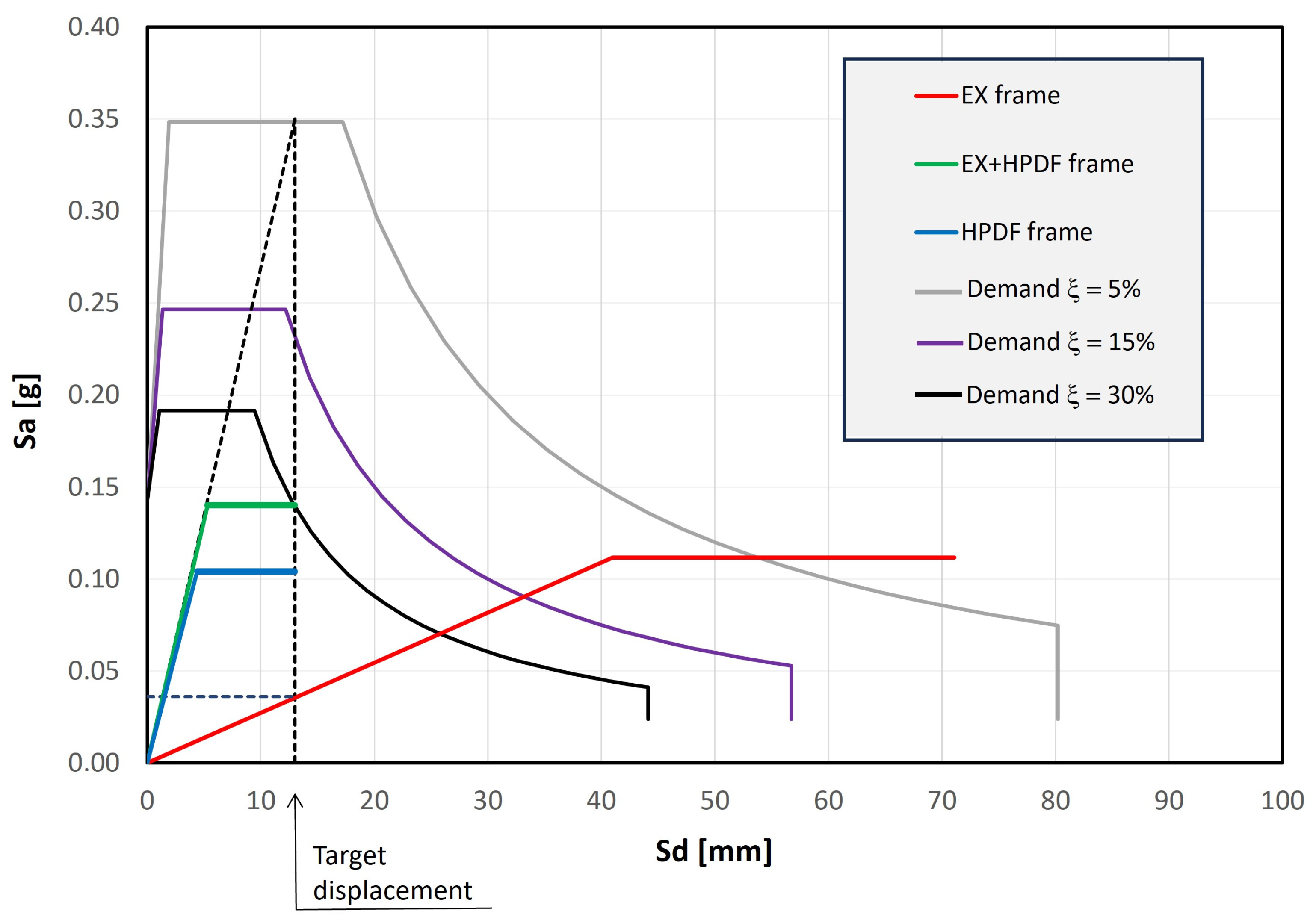
35]). The modal participation factor is adopted to convert the MDOF response into the SDOF response, obtaining the corresponding bilinear curve in the acceleration–displacement response spectrum (ADRS, red curve in
Figure 15).
Then, the allowed target displacement for the existing structure in the post-intervention condition must be defined. In this case, the main intervention goal is to avoid any brittle failure related to the RC members so that local strengthening interventions become unnecessary.
Figure 15 shows the vertical dotted line at a 13 mm displacement for the Y-direction, being the above-mentioned target displacement, which would trigger the first fragile collapse. The graph also shows the demand curves (related to elastic spectra reduced by 40% in order to obtain a seismic intensity equal to 60% of the design values) for different equivalent damping (ξ) values (namely 5, 15 and 30%, indicated with grey, purple and black curves, respectively). Once the total (existing + exoskeleton) stiffness is known (inclined dotted line), the larger the damping value, the lower the force threshold. Once the damping value is selected (in this case 30%), a horizontal line can be drawn to intersect the inclined dotted line. This results in the whole system’s bilinear (green) curve (existing + exoskeleton). The difference between the green and the red curves results in the blue curve, representing the exoskeleton design behaviour. Therefore, assuming an almost rigid behaviour of the braced exoskeleton frames, the dissipative S hinges can be designed to obtain the wanted global behaviour in terms of both the initial stiffness and equivalent damping (
Figure 16).
3.4. Energy Upgrading Design
To improve the energy performance of the building, ad hoc interventions were designed both on the external envelope and on the building systems. In particular, these interventions, described specifically below, are divided into the following:
Thermal insulation of vertical opaque walls through vacuum panels;
Thermal insulation of the roof through EPS panels;
Replacement of external windows;
Installation of a photovoltaic system with storage (grid-connected);
Relamping of the lighting system;
Replacement of the heating system with a heat pump;
Installation of a controlled mechanical ventilation (VMC) system.
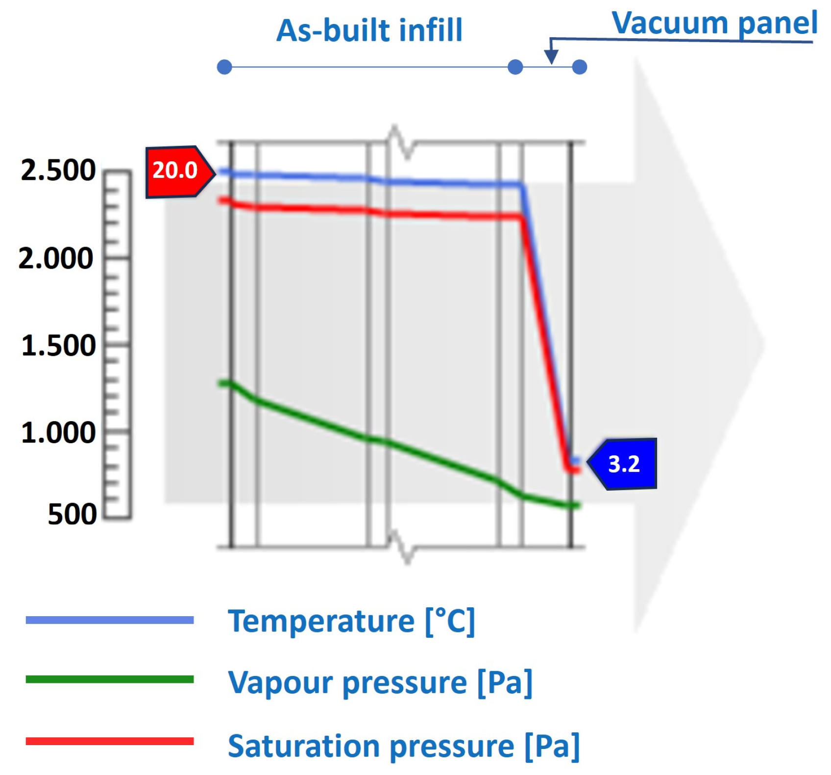
The energy efficiency intervention integrated with the seismic strengthening is represented by the external thermal coat, which is made with vacuum insulation panels with a thickness equal to 5 cm. As mentioned before, the choice of thickness was necessary to adapt the EIFS with seismic intervention, characterised by the installation of new frames adjacent to the existing ones through the purposely defined gap connections, thereby permitting a clearance between the two frames equal to 8 cm.
Each insulating panel is composed of a core, mainly of fibreglass, and a special jacket in fibreglass and an aluminium fabric that makes it much more resistant to cutting and erosion. This material has an extremely low conductivity, equal to 0.002 W/mK, which makes it possible to work even with much lower thicknesses than traditional EPS materials. With this intervention, it is possible to improve the transmittance of the upgraded infill walls from 1.031 to 0.039 W/m
2K (
Figure 17).
In addition to interventions on the vertical envelope walls, further interventions were planned for both the other envelope members (roof and windows) (
Table 1) as well as for systems (
Table 2), in order to improve the overall energy efficiency. To this end, the heating and lighting systems were completely replaced with high-efficiency modern systems, a new photovoltaic system was installed along with an accumulation system; finally, to improve the users’ comfort especially for pandemic conditions, a controlled mechanical ventilation system was installed. This latter installment does not provide any energy saving, but only a consumption that was accounted for in the total energy balance.
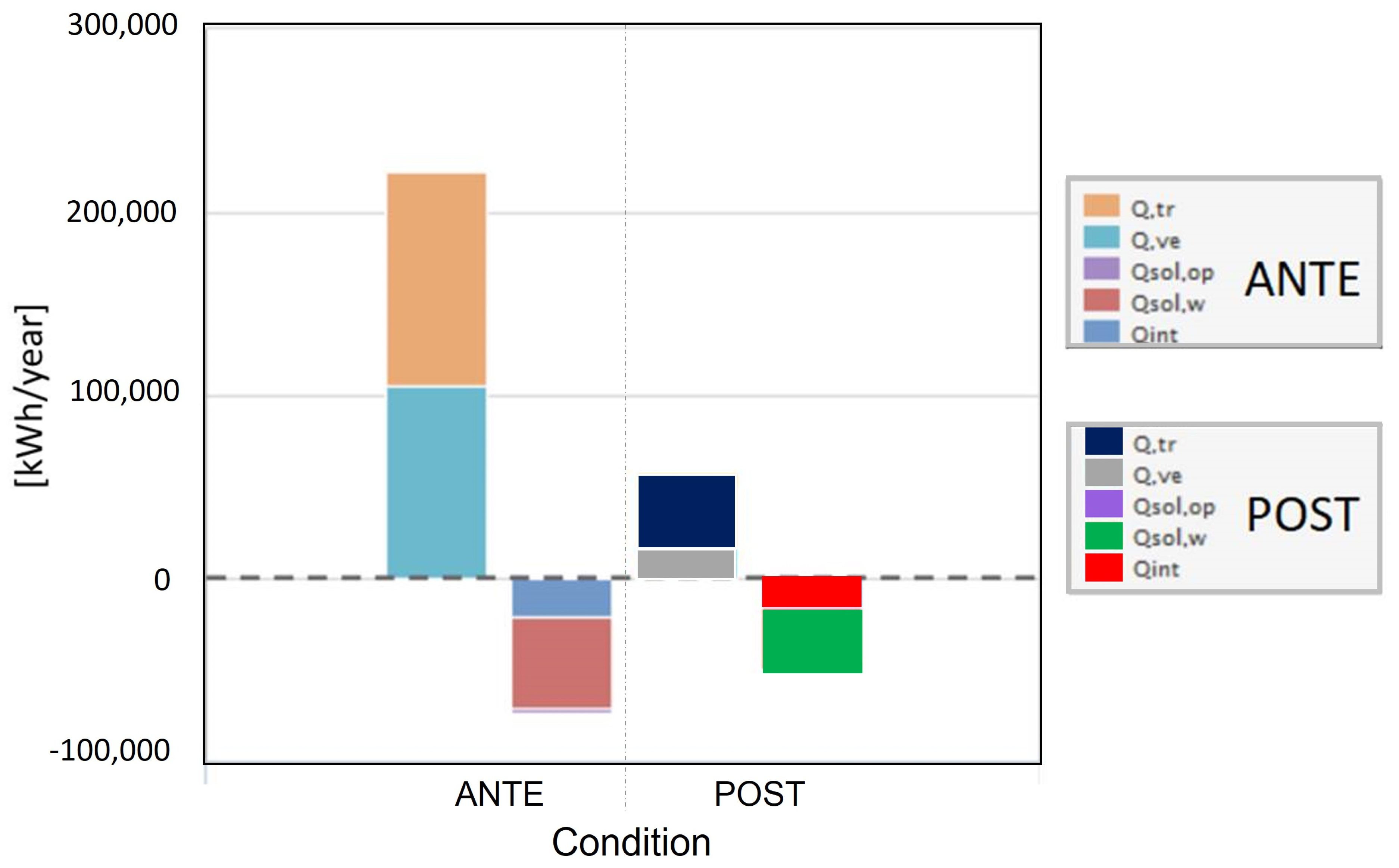
In
Figure 18, the energy balance for heating is reported for before and after the energy efficiency assessment. The results show the relevant reduction in the transmission losses due to the thermal barriers.
4. Results and Discussion
As already mentioned, the seismic upgrading intervention was designed to achieve a capacity–demand ratio equal to at least ζE = 0.6. This value corresponds to the minimum threshold required for Italian strategic buildings and schools, according to the Italian building code. The choice of the seismic strengthening technique was suggested on the basis of the need to avoid working inside the building, thus limiting the impact on school activities. The seismic design was devoted to preventing any fragile collapse in the beams, columns and joints, in order to avoid local strengthening intervention on individual members. Therefore, only a global intervention made completely for the exterior was designed. To easily accommodate its integration with the energy efficiency measures, a gap connection was developed between the old and the new exoskeleton structure. This allowed for the installation of 5 cm thick vacuum insulation panels able to drop the upgraded infill walls transmittance from 1.031 to 0.039 W/m2K, with a 96% decrease. Other interventions on the systems, lighting and renewable energy generation allowed for dramatic reductions in the energy consumption of non-renewable energy.
According to the method described in the Italian guidelines for seismic risk classification of constructions [
39], the expected earthquake annual loss (EAL) was computed for the ante- and post-intervention conditions. It was found that the seismic upgrading intervention was able to reduce the expected earthquake annual loss from 8.2% to 1.1%, saving 7.1% of the reconstruction costs (RC) each year, which can be assumed to be in the range of EURO 1450 to 1900/m
2 according to [
40]. It is worth remembering that the EAL is the expected costs due to earthquake damage paid each year.
The energy efficiency intervention allowed the unit energy consumption to drop from 189.60 kWh/m
2y to 34 kWh/m
2y, corresponding to an 83% reduction. Considering that the total estimated costs for the seismic and energy upgrading interventions are equal to EUR 544/m
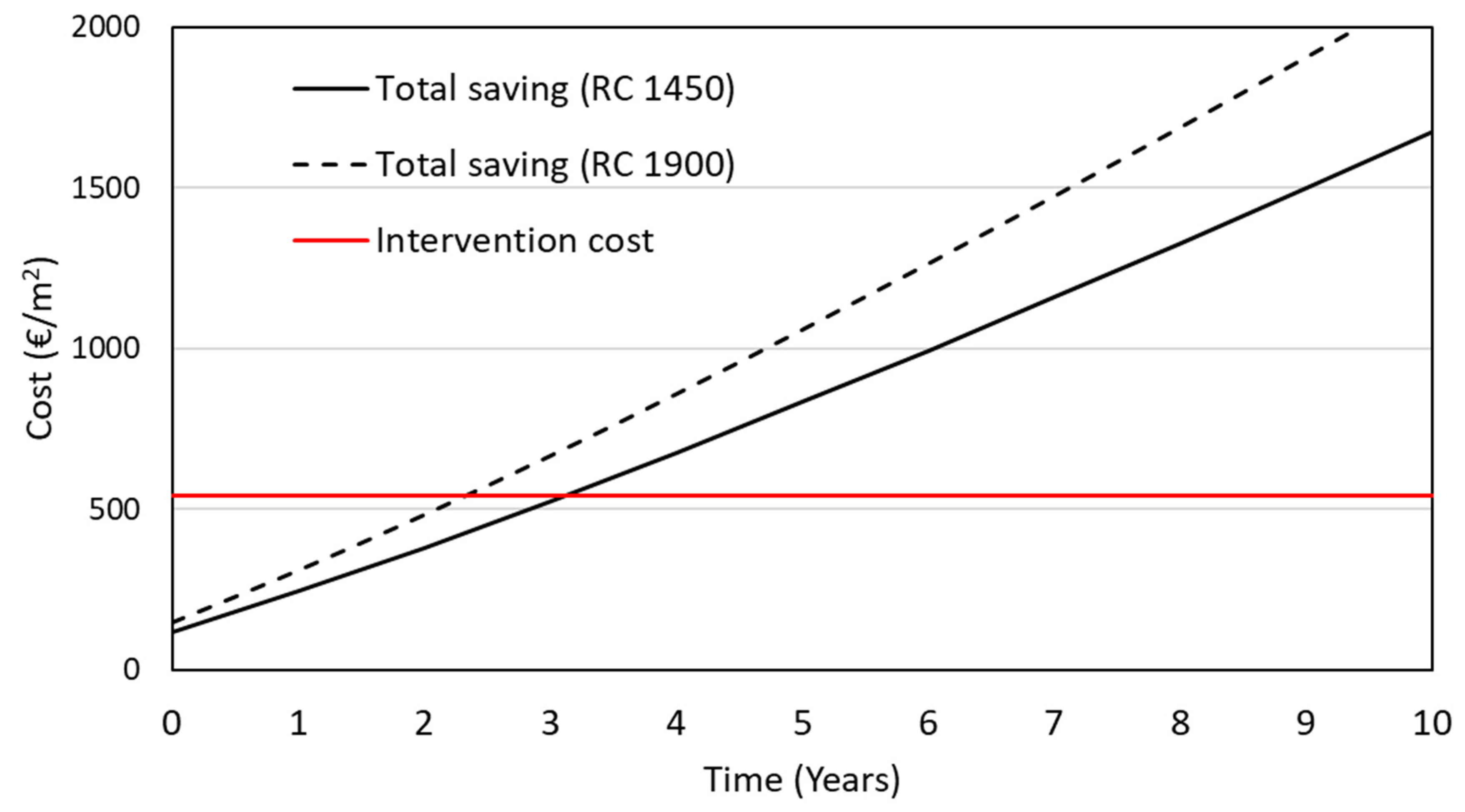
2, the time needed to recover these intervention costs through savings in terms of energy and seismic damage represents the payback time. To compute this timeframe, it was assumed that the intervention costs are constant, since the work is currently being carried out, while the reconstruction costs and the energy costs increase with time due to inflation. The latter costs are very high at the moment (2023) in Italy, being equal to about 8%. An optimistic assumption may be that inflation decreases by 1% each year until it stabilises at around 2% (
Table 3).
Based on these data and considering current energy prices (October 2023), the intervention payback time was calculated.
Based on
Figure 19, the payback time (intersection of savings over time and intervention cost curves) is equal to about 3.2 y for the case of RC = EUR 1450/m
2, and 2.3 y for the case of RC = EUR 1900/m
2. As expected, the higher the reconstruction costs, the shorter the payback time. It is worth stressing that most of the savings that yield such short payback times are due to the huge seismic savings, being 7.1% of RC each year.
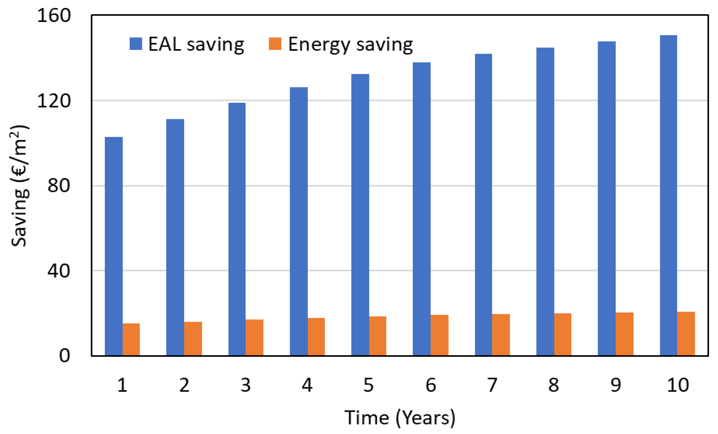
Figure 20 shows the amount of EAL and energy savings for the first ten years, for a case where the reconstruction costs are equal to EUR 1450/m
2.
The payback time in the case of energy savings only (absence of structural interventions for seismic upgrading) is equal to about 16 years; this demonstrates the need for financial incentives on behalf of government authorities to carry out these kinds of interventions, which will otherwise have limited cost–benefit advantages from an economic point of view. On the other hand, the benefits from the environmental point of view are always significant due to the significant reduction in non-renewable energy consumption [
41].
In order to compare the effectiveness of the proposed technique, recently studied exoskeleton solutions were explored. For example, in [
42] is described a design procedure regarding steel exoskeletons placed orthogonally to the existing building. This method does not explicitly consider the presence of energy efficiency interventions, highlighting that the proposed technique could serve as a possible support for energy efficiency upgrading and architectural restyling elements. The study reported in [
43] describes three different metal lightweight exoskeleton solutions applied to an RC school building. The solutions were integrated with coating elements able to provide thermal insulation. However, only two out of the three solutions were able to increase the seismic safety index to the minimum level required by the Italian code (ζ
E = 0.6), even though require some local interventions on the column members (on up to 30 members), which can be very disruptive. This leads to the conclusion that the technique proposed in this study has two clear advantages: (i) it provides dissipation elements that achieve high damping and, in turn, superior seismic performance; for this reason, local and highly impacting interventions inside the building can be avoided, although the minimum seismic safety index is achieved; (ii) the system was conceived to be coupled with external high-performance insulation panels that greatly improve the building’s energy efficiency.
5. Conclusions
This study presented a novel integrated intervention technique made up of dissipating exoskeletons equipped with so-called gap connections, which allow for the installation of high-performance insulation panels on the building envelope. This approach follows a five-pillar philosophy for building renovation sustainability described in this research.
The seismic intervention was applied to a case study school building, and was calibrated to avoid interventions to the building interior, thereby minimising disruptions and impact. The energy efficiency intervention was also devoted to renewing the systems, matching the latest standards related to consumption and air quality. The seismic capacity–demand ratio was increased by 5 times (i.e., from 0.12 to 0.6), while the total energy consumption was decreased by approximately 5.5 times.
Compared to other technical solutions, the method presented in this study avoids interventions to the building’s interior, which are usually significantly disruptive. This social cost has to be accounted for when rating a seismic–energy upgrading technical option.
Given the current inflation rates and reconstruction unit costs, the payback times are very short, demonstrating the economic convenience of carrying out these kinds of interventions. However, the savings are determined mainly by reductions in earthquake losses, which are often perceived as uncertain by citizens and administrative officers. However, the seismic damage savings suddenly appear when an earthquake happens, resulting in significant increases in community resilience, which can count on usable public buildings.


 ,
, 


