Article

Splitting Tensile Strength of Fly Ash-Modified Sand at Various Saturations and Curing Times

1
Department of Civil Engineering, Halu Oleo University, Kendari 93232, Indonesia
2
Department of Civil and Environmental Engineering, IPB University, Bogor 16680, Indonesia
3
Research Center for Biomaterials, National Research and Innovation Agency (BRIN), Cibinong 16911, Indonesia
*
Author to whom correspondence should be addressed.
Infrastructures 2022, 7(10), 126; https://doi.org/10.3390/infrastructures7100126
Submission received: 3 August 2022 / Revised: 1 September 2022 / Accepted: 15 September 2022 / Published: 22 September 2022

Abstract

:
Currently, a soil stabilization approach using fly ash as an effective choice for increasing soil stiffness and strength has emerged. With the presence of water, the lime in the fly ash would be separated, generating cementitious materials binding the grains of sand. In the present study, the influence of curing time and saturation during specimen preparation on the behavior of fly ash-modified sand was observed by performing a series of splitting tensile strength tests. It was found that the splitting tensile strength increases with fly ash content and curing time and decreases with saturation. The splitting tensile strength produced at 30% saturation was approximately two-fold higher than 100%, particularly at one month of curing time. However, the splitting tensile strength at higher saturations approaches lower, especially at longer curing times. Porewater evaporation accelerates the self-hardening occurring over time during curing. By increasing the fly ash percentage from 5% to 20% in the mixture, the splitting tensile strength increased by up to twenty-fold in the present study. An equation has been proposed as a function of porosity/volumetric fly ash content, curing time, and saturation during the preparation of the specimen.

1. Introduction

Chemical grouting as a binder has been widely used for soil improvement techniques to prevent liquefaction. Liquefaction usually occurs in saturated cohesionless granular soil such as sand. If subjected to cyclic loading, for example, during an earthquake, pore water pressure increases and scatters the sand grains, decreasing effective confining pressures. When the effective confining pressure approaches zero, the sand will experience a considerable loss of shear strength, triggering damage to the structure above it.
Various soil improvement techniques for liquefaction mitigation of problematic soil, such as densification, dewatering, replacement, and solidification using cement, epoxy, silicates, bentonite, and other chemical compounds, have also been developed [1,2]. Bio-grouting as another alternative for ameliorating soil resistance against liquefaction in terms of improving cohesion is emerged [2,3,4,5,6,7]. In addition to reducing liquefaction, the use of binders, especially in cohesionless granular soils, must also consider the cost of purchasing the binder itself. In that case, using industrial by-products around us needs to be considered. One of them that is cost-effective and can reduce environmental problems is fly ash. As an industrial by-product, fly ash (FA) has been determined to be a practical choice for increasing soil stiffness and strength through chemical processes [8,9]. This increase occurs because several kinds of fly ash contain lime (CaO), and pozzolan consists of alumina (Al2O3) and silica (SiO2) compounds. When fly ash is blended with soil, a chemical reaction occurs in the presence of water. This reaction separates lime (CaO) from fly ash.
CaO   +   H 2 O Ca OH 2
Ca OH 2 Ca 2 + + 2 OH
A pozzolanic compound, including calcium aluminate hydrate (CAH) and calcium silicate hydrate (CSH), would then be generated.
Ca 2 + + 2 OH +   SiO 2 CSH
Ca 2 + + 2 OH +   Al 2 O 3 CAH  
As a result, fly ash will bind particles of the soil and increase the stiffness and strength of that soil [10,11,12].
Laboratory investigations on the mechanical properties of fly ash-modified soils, such as tests on unconfined compressive strength, shear strength, California bearing ratio (CBR), and resilience modulus, have been frequently carried out [8,9,13,14,15,16,17,18]. The results show that soil stabilization with fly ash can effectively increase the stiffness and strength of the modified soil. With these benefits, fly ash as a binder is often used to improvet the fill soil layer [9,19,20], especially as compacted layers over soft soil. Because it is above the ground with low bearing capacity, the failure mechanism of the modified and compacted soil layer usually begins with cracks at the bottom of the compacted layers. It occurs when the splitting tensile strength, q t , has reached that layer [21]. Thus, q t is one of the appropriate parameters to evaluate the failure of the modified soil structure over soft soil. However, limited information about fly ash-modified soil q t is reported in the literature, especially in granular soils such as sand. The importance of the splitting tensile strength of soils is very often related to the tensile cracks that can occur in soil structures, such as embankments, dams, or slopes.
Consoli et al. (2014a, 2014b) [22,23] observed the effects of temperature on the splitting tensile strength of blended fly ash, lime, and sand. They found that at 25% FA and 14% moisture content, the splitting tensile strength of that blend increases by approximately five times with temperature increases (T) from 20 to 50 °C. Other researchers have tried to reveal the effect of moisture content instead of temperature by Consoli et al. (2014a, 2014b) [22,23] on the strength of modified soils Their test results reveal that the strength increases with optimum moisture content ( ω opt ), i.e., the moisture content ω at maximum dry density γ d max . On the other hand, Baldovino et al. (2018) [24] investigated the curing time effect on the q t of lime-modified silty soil. The curing time (CT) played an essential role in the change in q t . It increases with CT.
However, the scopes of previous attempts to predict q t changes by considering the index of the porosity/volumetric binder content with either T, CT, or ω have been limited at the optimal molding conditions. Little effort has been devoted to predicting the change in q t of FA-modified sand subjected to the combined parameters effects of the index of the porosity/volumetric of FA percentage n FA v , curing time (CT), and saturation during the preparation of specimen (Sr). In addition, the amount of water in previous studies predicting the q t of modified soils was built upon the optimum moisture content ω opt , producing the maximum dry density γ d max . In this research, the amount of water was determined based on the volume of water in the void at a relative density DR = 50%.
Simatupang et al. (2020) [15] investigated and revealed that the mechanical properties of sand modified with FA increase plausibly even though in a very small FA amount of 5%. Those alterations, however, are more significant at FA of approximately 20% or more and CT of at least 28 days. The mechanical properties of FA-modified sands could be doubled by reducing the saturation from 100% to 30%. These points clarify that FA can be used as an effective stabilizing agent. Furthermore, it is believed to increase the strength more significantly by reducing saturation during specimen preparation. The problem is that the minimum saturation capable of dissociating lime in FA was unclear.
Given the issues mentioned above, a series of splitting tensile strength tests were conducted to reveal the influences of saturation during the preparation of specimen Sr and curing time CT on the q t of FA-modified sand. FA-modified sand specimens were prepared at various parameters: FA percentage, curing time, and saturation. Microscopic images of FA-modified sand prepared at different saturations of 30% and 100% were utilized to analyze the morphology and distribution of gels on the sand surface. An empirical equation is generated to estimate q t of FA-modified sand as a function of n FA v separately at various values of either Sr or CT. Based on these generated equations, a new prediction q t equation in the form of a combined parameter function among n FA v , CT, and Sr is proposed. Moreover, this new prediction q t equation was revalidated using the same parameters observed in this study.

2. Materials and Methods

2.1. Materials

The primary materials used in this research were sand, fly ash (FA), and water. The sand was taken from the Pohara River, Konawe Regency, Southeast Sulawesi Province-Indonesia, passed through sieve No. 4, and was retained in sieve No. 200. The specific gravity of that sand is 2.66. The distribution of the sand grain size is presented in Figure 1. Before it was used, the sand was placed in a dry oven. The other material, fly ash, was received from PLTU Nii Tanasa, Konawe Regency. The FA’s specific gravity and grain sizes are 2.14 and less than 0.075 (passed the sieve No. 200), respectively. The fly ash is classified as class C, with a CaO content of more than 20%. In addition, it has pozzolanic properties, so it behaves like cement, which can bind to the mixture. The water used is tap water.

2.2. Methods

2.2.1. Material Testing

To determine the properties of the FA-modified sand, specific gravity (Gs) based on the Indonesian National Standard (SNI 03-1964-2008) [25] and density tests (for measuring void ratio-e) were carried out for each mixture, with the FA percentages determined at 5%, 10%, and 20% of the total weight of the mix. Then, as in Table 1, dry unit weights ( γ d ) were calculated based on those data and followed by determining void ratio (e) according to SNI 03-3637-1994 [26]. Void ratio (e) is determined based on Equation (5) by predetermining DR = 50%, as:
DR   = e max   e e max   e min

2.2.2. Mix Design

The sand was mixed with a specific fly ash content, namely, 5%, 10%, and 20% of the total weight of the mixture. After being mixed evenly, it was put into a plastic bag and then added to water according to the determined degree of saturation: 20%, 30%, 40%, 50%, 60%, 70%, 80%, and 100%. The sand, fly ash, and water mixture was then stirred evenly in a tightly sealed plastic bag. This was done to avoid evaporation during sample preparation. Next, the evenly distributed mixture was poured into a PVC mold with a height of 11 cm and a diameter of 5.5 cm layer by layer. Compaction was carried out in each layer with kerfs for up to 5 layers on each surface. After the mold was full, the surface was leveled and weighed to ensure it was at the targeted relative density of 50 ± 2%. A tolerance of ±2 is determined because the targeted relative density of 50% is difficult to achieve precisely. The molded mixture was stored indoors at a temperature of approximately 25 °C during the curing period of either 1, 2, 3, or 4 months. After the curing period, the mixture was removed from the mold. The diameter and height were remeasured to confirm no significant change in the dimensions of the specimen after the curing period. Then, the specimen was ready to be tested for splitting tensile strength. Graphically, the sample preparation processes are shown in Figure 2.

2.2.3. Sample Testing

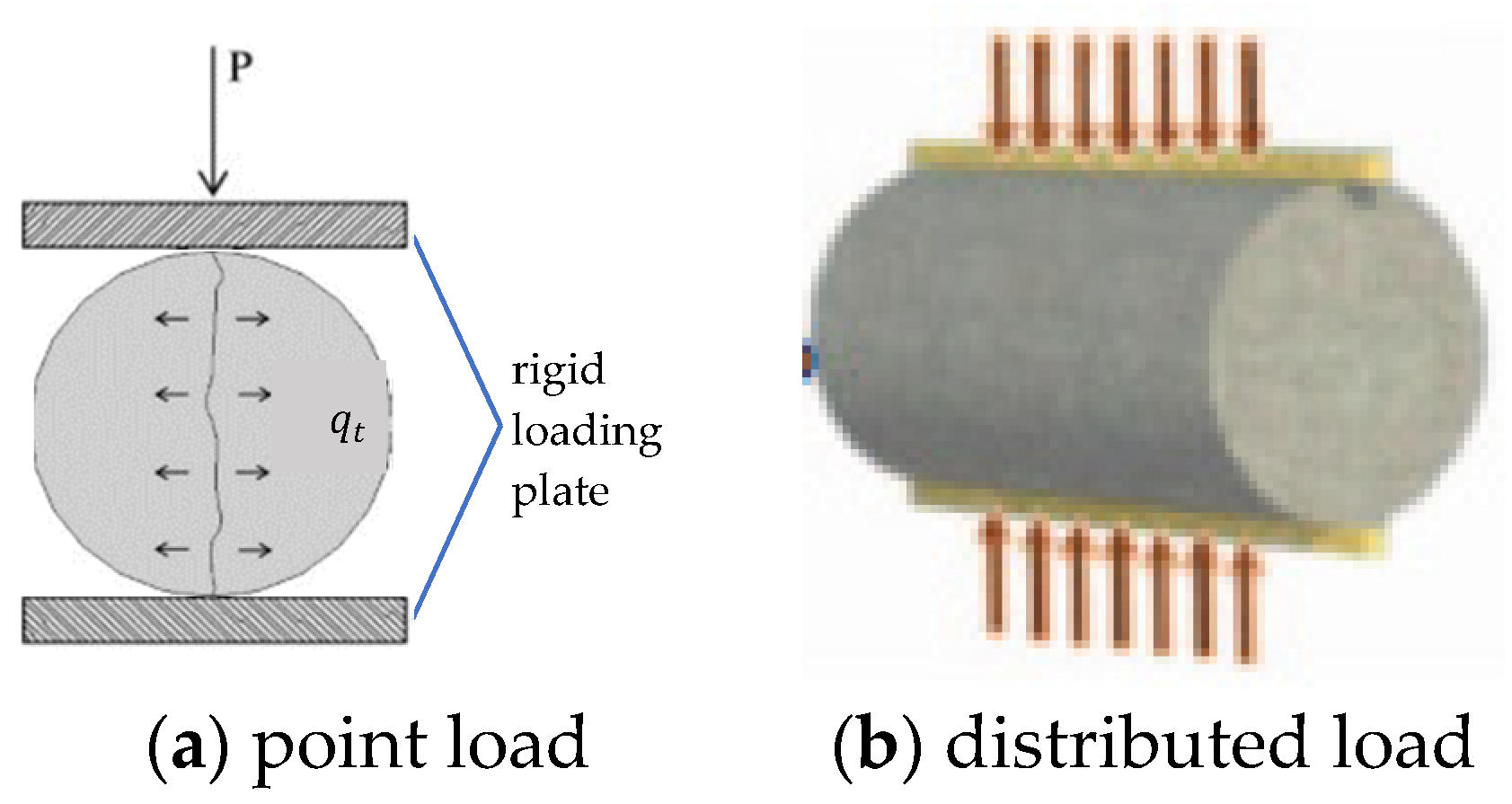
After the curing period was ended, a splitting tensile strength test was carried out for each specimen according to ASTM C496-11 (2011) [27]. In this test, the position of the sample was laid down horizontally between the rigid loading plates of the compression apparatus. Then, the load was vertically applied and increased along the two peaks of the specimen diameter, top and bottom, until it failed, as depicted in Figure 3a. Due to the rigid loading plate at the loading interface, the point load in Figure 3a is changed to distributed load in Figure 3b. Load readings were carried out at strains of 0.5%, 1%, 2%, …, and so on until they fail with a strain rate of approximately 1% per second.
The applied pressure induces tensile stresses, normal to the vertical diameter, and their magnitude is usually constant along the loaded diameter, as illustrated in Figure 3a. As follows, splitting tensile strength is calculated based on the assumption that failure occurs at the maximum tensile stress according to ASTM C496-11 (2011) [27].
q t = 2 P π LD
q t = splitting tensile strength; P = load applied at failure; L = specimen length; and D = specimen diameter.

2.2.4. Testing Conditions

The conditions of the test were prepared more conscientiously for investigating the influences of the parameters, consisting of FA percentage, CT, and Sr, on the q t of FA-modified sand. The q t tests were conducted at three different FA percentages of 5%, 10%, and 20%. These contents were determined following the previous test results obtained by researchers [15,16,17]. They revealed that a significant increase, approximately ten times higher, in the shear strength of the FA-modified sand, compared to bare sand, could be contributed by a small amount of FA of approximately 5%. In terms of unconfined compressive strength, the more significant improvement occurred in FA with a minimum percentage of 20% and CT for at least one month [15]. The CTs in the present study were 1–4 months.
Saturations during sample preparation Sr were predetermined, ranging from 20% to 100% with 10% spacing. It was achieved by calculating the water volume ( V w ) needed at the given Sr, according to:
Sr   = 1 +   e e · V w V ;   ( V = total   volume )
These Sr values were used to determine the optimal Sr that produces the maximum q t and the minimum Sr that is capable of completely dissociating lime from FA. The targeted relative density, DR, for all specimens was 50%. The amount of material used in the present study was calculated as shown in Table 2. The weight of dry sand depends on the amount of FA (in weight percent) in the mixture regardless of Sr. Meanwhile, the volume of water required is highly dependent on the content of FA and Sr.

3. Results and Discussion

3.1. Failure Mode of the Specimen

The sample failure modes observed in the splitting tensile strength tests are shown in Figure 4, either in the vertical (Figure 4a) or parallel (Figure 4b) direction to loading. The two failure crack modes are precisely between the two rigid loading plates and coincide with the loading direction. Basu et al. (2013) [28] indicate that the cementation material used is evenly distributed throughout the test object. Because crack failure usually occurs in the weakest part of the modified object being studied, where there is no cementitious material. In other words, all parts of the modified object have the same strength.

3.2. Splitting Tensile Strength of the FA-Modified Sand

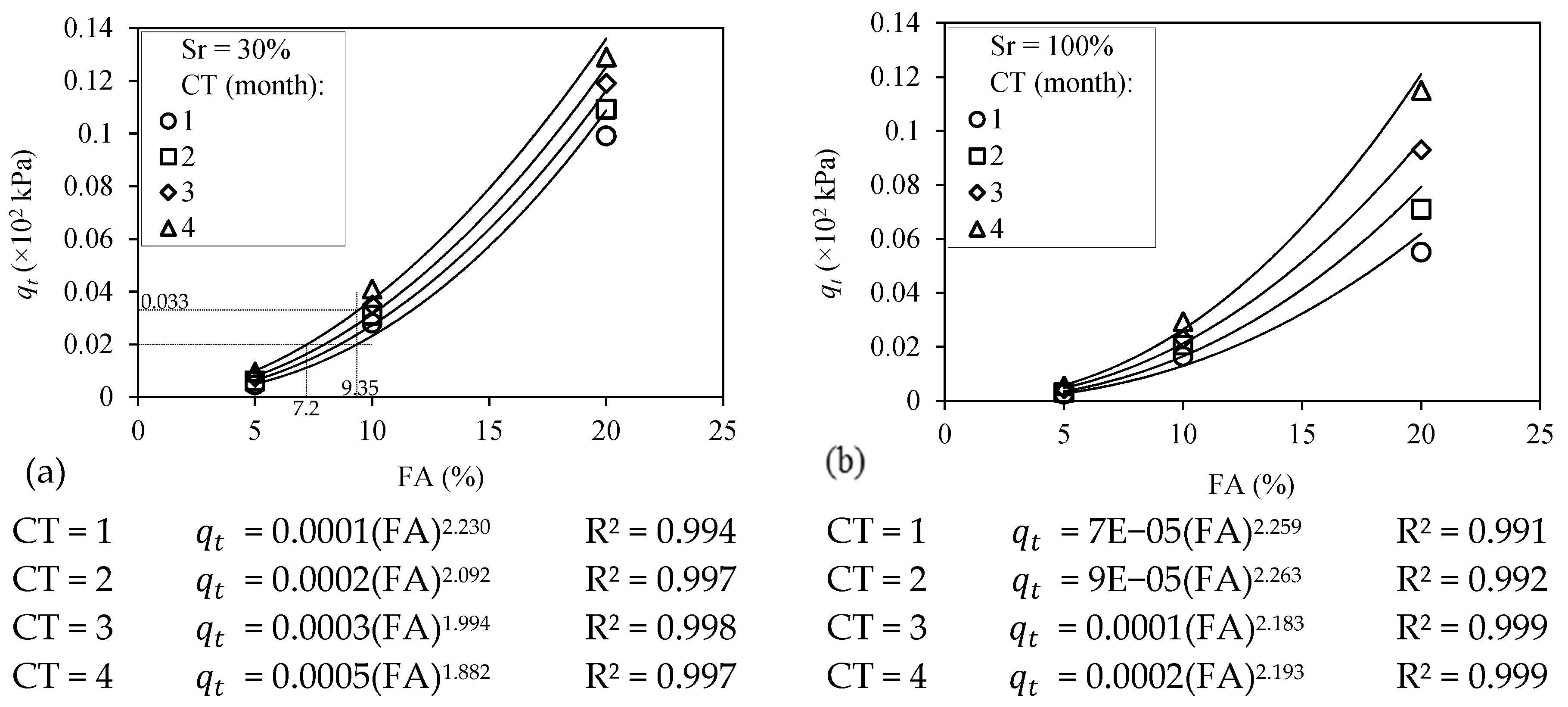
Alterations of the splitting tensile strength ( q t ) of sand modified with FA at various parameters of FA percentage, curing time, and saturation are shown in Figure 5, Figure 6 and Figure 7. Figure 5 shows the strength at particular saturation of 30% and 100% and various FA percentages and CT. It is clearly shown that q t increases with either FA percentage or CT as expected in all cases of saturation observed, represented by Sr 30% and 100%. The higher the FA percentage mixed in the specimen, the larger and stronger the bond produced during curing. However, in terms of differences in curing time, the strength improvement in the bond that binds sand grains was insignificant at a low FA percentage of 5%, as shown graphically in Figure 5. It means optimal strength has been reached at one month of age regardless of saturation during sample preparation. This trend agrees with that observed from investigations on fine sand with cement [29].
Figure 5a shows that the addition of FA from 5% to 20% could upgrade strength gain by up to twenty-fold, from q t 5 % = 0.005 × 10 2 kPa at 5% FA to q t 20 % = 0.099 × 10 2 kPa at 20% FA, especially on one month CT. However, this strength gain appears to decrease to approximately fourteen-fold, from q t 5 % = 0.01 × 10 2 kPa at 5% FA to q t 20 % = 0.129 × 10 2 kPa at 20% FA on four-month CT. A previous study also noted a similar trend: a significant increase in strength gain from FA = 20% modified sand on CT for one month and slowed after that [15]. They conducted unconfined compressive strength tests on days 7, 14, 28, and 56. The strength gain was low rate on specimens tested on days 7 and 14. However, there was a significant increase in the strength gain of the tested specimens on day 28. This increase continued until day 56 but at a lower rate when compared to the strength gain achieved on day 28 (a slowdown in terms of strength gain). Suitable agreement has also been shown in the other previous test results prepared by researchers using cement [29] and lime [22] as a binder. They concluded that small binder portions could significantly upgrade strength gain [22,29] at CT = 28 days [22]. In a test prepared by Consoli et al. (2014a) [22], they concluded to avoid increasing the curing period to more than 28 days, which resulted in only a slight improvement in q t .
Using the best-fit curves of power function, the coefficients of determination R 2 are more than 0.99 for all CT observed, as shown in Figure 5. A certain splitting tensile strength can be achieved either by a combination of (i) lower CT and larger FA dosages or (ii) higher CT and smaller FA dosages. Based on Figure 5a, a splitting tensile strength of 0.02 × 10 2 kPa can be attained by a CT = 1 month and FA = 9.35% or CT = 4 month and FA = 7.2%.
On the other side, at the same dosage of FA = 9.35% treated at different CT for one month and four months, splitting tensile strength was gained by 0.02 × 10 2 kPa and 0.033 × 10 2 kPa, respectively. The slope of the curve increases with FA dosage and goes higher with higher FA. It illustrates a sharp jump in q t at higher dosages of FA.
The effect of saturation during the specimen preparation on the q t of sand modified with 20% FA at different CTs is presented in Figure 6. The figure shows that 20% saturation does not seem sufficient to dissociate the lime that consisted of 20% FA in generating cementitious and pozzolanic gels. Consequently, some FA that filled the pores did not work perfectly in binding sand particles, causing low strength.
Based on Figure 6 and Figure 7b, q t increases sharply by adding saturation to a value of at least approximately 30%. However, this increase is higher at a lower saturation, 30%, decreasing with adding in saturation. Therefore, the minimum saturation that could completely dissociate the lime in the 20% FA in this study was approximately 30%. It is clear from Figure 6 and Figure 7b that there is a significant amelioration in the q t of the FA-modified sand by adding saturation from 20% to 30%. On the other hand, the q t of the FA-modified sand at 30% Sr was approximately two times higher than that at 100% Sr, especially at a low CT of one month. The q t is higher at a low saturation of 30% due to the gels’ effectiveness. As marked explicitly in Figure 8a, they agglomerated at the contact surfaces. Under that condition, the water is concentrated in the sand matrix, forming a menisci shape. Then, the cementitious and pozzolanic reactions occurred specifically at that position. Therefore, FA would bind sand grains effectively with water in their mixture at the contact point, directly and effectively contributing to the strength enhancement.
At higher saturations, the entire surface of the sand would be moistened by water and bound by FA generated by the chemical reaction, as shown in Figure 8b. However, the presence of gels on the sand surface outside the contact surface would not significantly affect the strength of the sand-FA mixture. Therefore, the bond strength is not determined by the amount of FA in the mixture. Instead, it is more determined by the position of the gel on the sand surface.
The effectiveness of lowering saturation during the preparation of specimens on FA-modified sand has been noted previously [15,16,17]. In particular, researchers have demonstrated this advantage in different sands modified with other cementitious materials using scanning electron microscopy (SEM) images [3,4,30]. They confirmed that the agglomerated cementitious material on the grains of the sand contact surface would significantly contribute to the strength amelioration at low saturation. In contrast, cementitious material was distributed evenly on the sand surface at a higher saturation. As a result, limited cementitious material was on the contact surface, producing a slight strength improvement.
The improvement in the q t of sand modified at 20% FA during curing at sundry saturation is depicted in Figure 7. Both graphs display the same data but have different performances. Figure 7a shows the trend of q t during curing at 20% FA, where q t increases with CT in all cases of saturation observed. Figure 7b shows the change in q t at the same FA percentage of 20% and at a specific CT treated at different Sr, as presented in the figure, during sample preparation. At a low saturation of approximately 30%, the minimum saturation capable of properly dissociating lime in the FA, q t is higher, but it slows down at a longer CT.
Nevertheless, it still changes in the q t magnitude at a minimal rate, indicating that the pozzolanic reaction continues. This reaction between silica, alumina, and lime that existed in the FA would produce a new cementitious material binding the soil particle, adding strength to the previous one. This trend agrees with the previous test results from several researchers [10,11,12,15,31]. They confirmed that strength gain is run slowly at the initial stage of the CT of less than one month and then increases significantly on CT at about one month and decelerates thereafter.
However, in a higher Sr, the q t is lower, and it comes close to the q t of modified sand at lower saturation in a higher CT. As explained before, q t is lower at higher Sr because of the uniform distribution of gels over the entire sand surface. Therefore, a limited gel is directly associated with the strength development in the contact surface. On the other hand, the q t of modified sand at higher saturation approaches lower saturation due to a reduction in saturation accelerating self-hardening during curing. Figure 7b shows that the strength gains are almost identical, although at different saturations.

3.3. Microscopic Images of the FA-Modified Sand

Figure 8 shows the microstructures of the modified sand using a scanning electron microscopy (SEM) image. The formation of the gel on sand grain at 20% FA cured at different saturations Sr of either 30% or 100% was observed using those images. The images in Figure 8a clearly show that at a low saturation of Sr = 30%, the gel congregated at the interparticle contact point. It binds sand particles and establishes a matrix connection between grains. Some sand surfaces that were not moistened with water were not coated with FA. Consequently, the gel agglomerated at the contact surface where the menisci shape of pore water occurred. Under this condition, the dissolution of silica ( SiO 2 ) and alumina ( Al 2 O 3 ) from FA react with Ca 2 + ions in the presence of pore water, as described in Equations (1) to (4), generating CSH and CAH gels. The generating pozzolanic compounds, CSH and CAH gels, would bind the sand particles, particularly on the contact surface where the pore water is located, to form a meniscus. This compound crystallizes and hardens over time, increasing the modified sand’s strength.
At a higher saturation, Sr = 100% during the specimen preparation; however, the gels were uniformly distributed, as imaged in Figure 8b. In this case, the natural texture of the sand grain was utterly covered by FA and could not be distinguished from one another. Because the whole surface of the sand is covered by water, the pozzolanic reaction generating CSH and CAH gels takes place entire sand surface. Hence, gels at the contact surface are quite limited, producing low strength.

3.4. The Empirical Strength q t Formulation of the FA-Modified Sand

Previous studies have revealed that specimen porosity and binder-agent volumetric content are the principal parameters affecting the strength q t of the modified sand [22,23,29]. According to the test results prepared by Consoli et al. (2010) [29], the alteration in q t is expressed as a function of the ratio between porosity, n, and volumetric of cement content, C v , defined by Equation (8).
q t = f n C v k ,
where k is the adjustment parameter. This equation was adopted in empirically formulating the q t of the FA-modified sand observed in this study by changing C v with FA v . The porosity n was determined using Equation (9) as a function of the void ratio.
n = e 1 + e ,
On the other hand, the volumetric of FA percentage, FA v , is a comparison between the FA volume and the total volume of the specimen, expressed as Equation (10) [32].
FA v = 100 FA c · γ d 1 + FA c · γ S FA ,
where γ d = dry unit weight of the mixture (g/cm3); FA c = fly ash content (%); and γ S FA = unit weight of FA (g/cm3). Based on Equation (10), the volumetric of FA content increases with the FA percentage, decreasing the porosity. Consequently, the ratio of the porosity/volumetric of FA percentage n FA v decreases. Consoli et al. (2014a, 2014b, 2010) [22,23,29], along with these test results, remarked that the q t of modified sand increases with increasing binder-agent content and decreasing porosity. The increase in q t is higher when the volumetric of binder agent increases exponentially [22,23,24,32,33,34]. In this study, an exponent of k = 0.06 on FA v k , which replaces C v k according to Equation (8), provides the best fit for the relationship between q t and n FA v of the mixture between sand and FA.
Figure 9 shows the relationship between q t and the normalized porosity, n FA v 0.06 , at various Sr and CT. At the same CT, the trend was developed based on the group data in saturation Sr. q t decreases with normalized porosity and saturation during the preparation of specimen Sr and increases with CT. Previous test results, along with these test results, have emphasized the beneficial effect of lowering porosity and saturation and increasing CT on q t , as explained above. As shown in Figure 9, these trends follow the test results of Baldovino et al. (2018) [24]. They tested lime-modified silty soil at the optimum molding point, various porosity/lime ratios, and different CTs.
The best fit of the relationships between q t and n F A v has been established at a specific CT of either 1, 2, 3, or 4 months and any saturations observed. As shown in Figure 10, the effect of saturation during the preparation of the specimen on q t was defined. The q t at 50% and 70% Sr was not included in this figure because their data under investigation are only at a 20% FA percentage, neither 5% nor 10%. The graph gets closer at higher CT, showing that continuous strengthening and hardening occurred during the curing process.
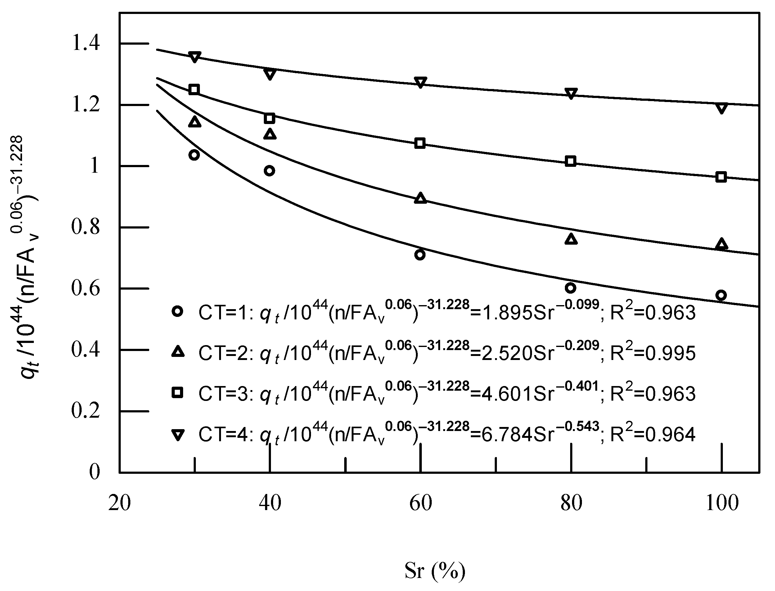
Based on Figure 10, a constant has been obtained by dividing those equations presented in the figure with the term 10 44 n / FA v 0.06 31.228 , which seems to decrease with saturation. The relationship between each constant obtained, the result of dividing q t with the term 10 44 n / FA v 0.06 31.228 , and its corresponding saturation at each overviewed CT is depicted in Figure 11. The figure shows that the q t decreases with saturation in all cases of observed CTs. The best fit of that descending trend seems to be well illustrated by the power function. The coefficient of determination R 2 of the resulting function is close to one, as presented in Figure 11. It agrees with the previous test results reported by Consoli et al. (2016) [32], in which the form of a power function was used to determine the effect of water content on the q t of the modified specimen.
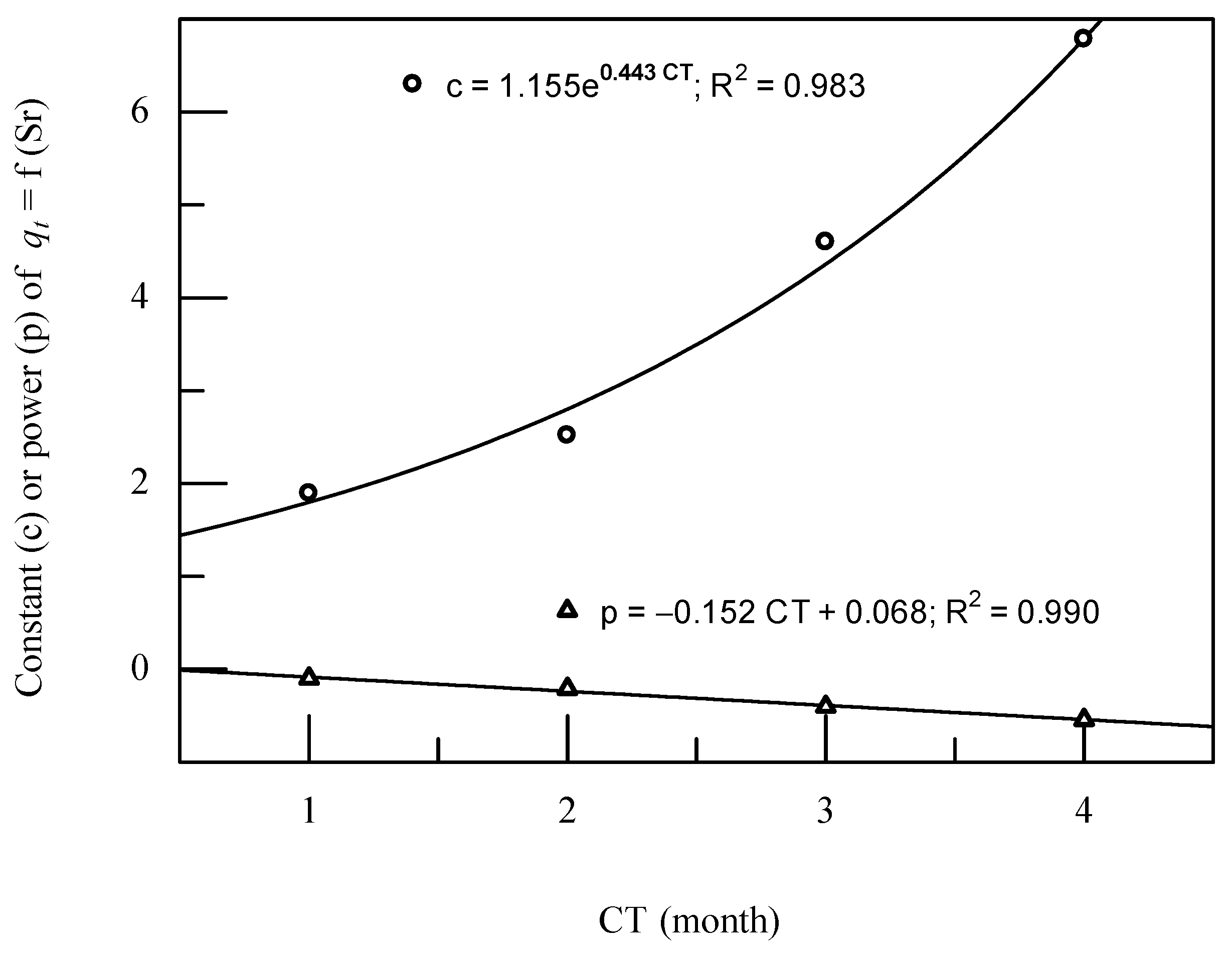
On the other hand, the curing time also significantly affects the q t change. Based on Figure 11, the function’s constant and power, q t = f(Sr), increase and decrease with CT, respectively. By connecting each constant and each power with its corresponding CT, CT’s and Sr’s effect on the q t could be formulated. As presented in Figure 12, the best fit illustrated by the highest coefficient of determination R 2 of their correlation is represented. The trends of the constants and powers of the functions presented in Figure 11 are well illustrated by the exponential and linear functions, respectively. Then, the proposed equation for predicting q t in this study as a function of the n FA v ratio, Sr, and CT is shown in Equation (11).
q t 10 44 n / FA v 0.06 31.228 = 1.155 e 0.443 CT Sr 0.152   CT + 0.068 ,
To validate the proposed equation, Equation (11) on predicting q t , the same parameters as in observation, porosity, curing time, saturation, and fly ash content, have been applied in prediction. The q t results based on observations and predictions using Equation (11) at various parameters examined have been plotted on Cartesian coordinates as abscissa and ordinate, respectively, as depicted in Figure 13. The equation giving similar values between the predicted and observed q t was inserted into the grouped data plot. The coefficient of determination was then assessed based on the equation inserted. The figure shows that the match between the inserted equation and the test results, predictions, and observations of 72 test specimens is almost perfect, with a coefficient of determination R 2 = 0.996.
Figure 13 shows the plot points between the observed and predicted q t at different CTs grouped in a specific Sr. There were four different CTs of 1, 2, 3, and 4 months at every Sr evaluated and three various porosity/volumetric of FA percentage ratios at each observed CT, except for Sr = 50% and 70%. With the exception of Sr, there was only one n FA v ratio at every examined CT, which was 20% FA. The data plotted in Figure 12 lie on or close to the line inserted, indicating a similar value between the predicted and observed q t . It implies that the proposed equation can be used well to predict the q t value of the FA-modified sand.

4. Conclusions

FA-modified sand specimen preparations were conducted under various saturation (20–100%) and fly ash content (5%, 10%, and 20%). In addition, splitting tensile strength investigations were performed after a curing time of 1–4 months. The splitting tensile strength behavior of FA-modified sand was observed to reveal the effects of the testing parameters fly ash content, curing time, and saturation during the specimen preparation. Furthermore, the prediction equation in the combination function of parameters, namely, porosity/volumetric FA percentage index, curing time, and saturation, has been proposed and revalidated. The main points as the summaries of those test results are as follows.
The slope of the q t curve increases with FA dosage and goes higher with higher FA. It illustrates that there is a sharp jump in q t at a higher dosage of FA = 20%, especially at low CT of 1 month. A small amount of FA can significantly upgrade the q t of fly ash-modified sand.
The FA stabilization approach greatly affects the q t of the modified sand. The increase in the FA dosage in the pores increases the q t of the FA-modified sand. It will add the size of the grains directly relating to the strength amelioration.
The strength improvement occurs over time during curing due to pozzolanic activity, self-cementation, and self-hardening. The evaporation of moisture content in the specimen will accelerate the self-hardening, which can be achieved by reducing the saturation during specimen preparation.
Gels will accumulate at the contact surface between grains at low saturation, generating a stronger specimen. In contrast, the gel will separate evenly on the sand surface at high saturation, producing fewer gels at the contact point between the sand particles and the weaker specimen. SEM images have revealed these terms.
At a specific saturation, a certain splitting tensile strength can be achieved either by combining (i) lower CT and larger FA dosages or (ii) higher CT and smaller FA dosages.
The normalized porosity to volumetric of FA percentage, n FA v k , with an adjusting exponent k = 0.06, has been shown to be a suitable variable for evaluating the splitting tensile strength of FA-modified sand on various FA, CT, and Sr.
The splitting tensile strength of FA-modified sand increases with FA and CT but decreases with saturation Sr during sample preparation.
The proposed equation can be applied well in predicting the q t of FA-modified sand at a specific DR of 50% with various parameters, such as FA percentage, curing time, and saturation during the specimen preparation. It was created by taking into account the influences of those parameters.

Author Contributions

Conceptualization, M.S. and R.S.E.; methodology, M.S.; software, S.; validation, W.M., H.P. and D.H.Y.Y.; formal analysis, M.S.; investigation, W.M.; resources, S.; data curation, H.P.; writing—original draft preparation, M.S.; writing—review and editing, R.S.E. and H.P.; visualization, S.; supervision, D.H.Y.Y.; project administration, W.M.; funding acquisition, R.S.E. All authors have read and agreed to the published version of the manuscript.

Funding

This research was funded by the Ministry of Education, Culture, Research, and Technology of the Republic of Indonesia, grant number: 52/UN29.20/PG/2022.

Data Availability Statement

The data presented in this article is available upon request from corresponding author.

Acknowledgments

The authors want to acknowledge all parties involved in this research. Special thanks are conveyed to the Ministry of Education, Culture, Research, and Technology of the Republic of Indonesia as the funder. Those supports are gratefully acknowledged.

Conflicts of Interest

The authors declare no conflict of interest.

References

  1. Kitazume, M.; Okamura, M. Contributions to “Soils and Foundations”: Ground Improvement. Soils Found. Jpn. Geotech. Soc. 2010, 50, 965–975. [Google Scholar] [CrossRef]
  2. El Mohtar, C.S.; Bobet, A.; Santagata, M.C.; Drnevich, V.P.; Johnston, C.T. Liquefaction Mitigation Using Bentonite Suspensions. J. Geotech. Geoenviron. Eng. 2013, 139, 1369–1380. [Google Scholar] [CrossRef]
  3. Simatupang, M.; Okamura, M. Liquefaction Resistance of Sand Remediated with Carbonate Precipitation at Different Degrees of Saturation during Curing. Soils Found. 2017, 57, 619–631. [Google Scholar] [CrossRef]
  4. Simatupang, M.; Okamura, M.; Hayashi, K.; Yasuhara, H. Small-Strain Shear Modulus and Liquefaction Resistance of Sand with Carbonate Precipitation. Soil Dyn. Earthq. Eng. 2018, 115, 710–718. [Google Scholar] [CrossRef]
  5. Simatupang, M.; Sukri, A.S.; Nasrul; Sulha; Putri, T.S. Effect of Confining Pressures on the Shear Modulus of Sand Treated with Enzymatically Induced Calcite Precipitation. IOP Conf. Ser. Mater. Sci. Eng. 2019, 615, 012042. [Google Scholar] [CrossRef]
  6. Montoya, B.M.; DeJong, J.T.; Boulanger, R.W. Dynamic Response of Liquefiable Sand Improved by Microbial-Induced Calcite Precipitation. Géotechnique 2013, 63, 302–312. [Google Scholar] [CrossRef]
  7. El Mohtar, C.S.; Bobet, A.; Drnevich, V.P.; Johston, C.T.; Santagat, M.C. Pore Pressure Generation in Sand with Bentonite: From Small Strains to Liquefaction. Géotechnique 2014, 64, 108–117. [Google Scholar] [CrossRef]
  8. Prabakar, J.; Dendorkar, N.; Morchhale, R.K. Influence of Fly Ash on Strength Behavior of Typical Soils. Constr. Build. Mater. 2004, 18, 263–267. [Google Scholar] [CrossRef]
  9. Trzebiatowski, B.B.D.; Edil, T.B.; Benson, C.H. Case Study of Subgrade Stabilization Using Fly Ash: State Highway 32, Port Washington, Wisconsin. Benef. Reuse Waste Mater. Geotech. Transp. Appl. GSP 2004, 127, 123–136. [Google Scholar]
  10. Amadi, A.A.; Osu, A.S. Effect of Curing Time on Strength Development in Black Cotton Soil – Quarry Fines Composite Stabilized with Cement Kiln Dust (CKD). J. King Saud Univ.-Eng. Sci. 2018, 30, 305–312. [Google Scholar] [CrossRef]
  11. Oriola, F.O.P.; Moses, G. Compacted Black Cotton Soil Treated with Cement Kiln Dust as Hydraulic Barrier Material. Am. J. Sci. Ind. Res. 2011, 2, 521–530. [Google Scholar] [CrossRef]
  12. Salahudeen, A.B.; Eberemu, A.; Osinubi, K.J. Assessment of Cement Kiln Dust-Treated Expansive Soil for the Construction of Flexible Pavements. Geotech. Geol. Eng. 2014, 32, 923–931. [Google Scholar] [CrossRef]
  13. Brooks, R.M. Soil Stabilization With Flyash and Rice Husk Ash. Int. J. Res. Rev. Appl. Sci. 2009, 1, 2076–7366. [Google Scholar]
  14. Edil, T.B.; Acosta, H.A.; Benson, C.H. Stabilizing Soft Fine-Grained Soils with Fly Ash. J. Mater. Civ. Eng. 2006, 18, 283–294. [Google Scholar] [CrossRef]
  15. Simatupang, M.; Mangalla, L.K.; Edwin, R.S.; Putra, A.A.; Azikin, M.T.; Aswad, N.H.; Mustika, W. The Mechanical Properties of Fly-Ash-Stabilized Sands. Geosciences 2020, 10, 132. [Google Scholar] [CrossRef]
  16. Simatupang, M. Effectiveness of Lowering Saturation on Residual Shear Strength of Sand Stabilized with Fly-Ash. IOP Conf. Ser. Earth Environ. Sci. 2021, 622, 012003. [Google Scholar] [CrossRef]
  17. Simatupang, M.; Mangalla, L.K.; Muhaimin, L.O.; Aldy, M.; Aji, I.C.; Jalbanirah; Jamin, M.; Marteni, L.O.A.; Rahmat; Ardiyansyah. The Ultimate Shear Strength of the Fly Ash-Improved Sands. IOP Conf. Ser. Earth Environ. Sci. 2021, 871, 012061. [Google Scholar] [CrossRef]
  18. Tastan, E.O.; Edil, T.B.; Benson, C.H.; Aydilek, A.H. Stabilization of Organic Soils with Fly Ash. J. Geotech. Geoenviron. Eng. ASCE 2011, 137, 819–833. [Google Scholar] [CrossRef]
  19. Cetin, B.; Aydilek, A.H.; Guney, Y. Stabilization of Recycled Base Materials with High Carbon Fly Ash. Resour. Conserv. Recycl. 2010, 54, 878–892. [Google Scholar] [CrossRef]
  20. Senol, A.; Edil, T.B.; Bin-Shafique, M.S.; Acosta, H.A.; Benson, C.H. Soft Subgrades Stabilization by Using Various Fly Ashes. Resour. Conserv. Recycl. 2006, 46, 365–376. [Google Scholar] [CrossRef]
  21. Consoli, N.C.; Rosa, F.D.; Fonini, A. Plate Load Tests on Cemented Soil Layers Overlaying Weaker Soil. J. Geotech. Geoenviron. Eng. 2009, 135, 1846–1856. [Google Scholar] [CrossRef]
  22. Consoli, N.C.; da Rocha, C.G.; Silvani, C. Devising Dosages for Soil-Fly Ash-Lime Blends Based on Tensile Strength Controlling Equations. Constr. Build. Mater. 2014, 55, 238–245. [Google Scholar] [CrossRef]
  23. Consoli, N.C.; da Rocha, C.G.; Silvani, C. Effect of Curing Temperature on the Strength of Sand, Coal Fly Ash, and Lime Blends. J. Mater. Civ. Eng. 2014, 26, 06014015. [Google Scholar] [CrossRef]
  24. Baldovino, J.A.; Moreira, E.B.; dos Santos Izzo, R.L.; Rose, J.L. Empirical Relationships with Unconfined Compressive Strength and Split Tensile Strength for the Long Term of a Lime-Treated Silty Soil. J. Mater. Civ. Eng. 2018, 30, 06018008. [Google Scholar] [CrossRef]
  25. SNI 03-1964-2008; How to Test the Specific Gravity of the Soil. BSN: Jakarta, Indonesia, 2008; (In Bahasa Indonesia).
  26. SNI 03-3637-1994; Soil Unit Weight Test Method. BSN: Jakarta, Indonesia, 1994; (In Bahasa Indonesia).
  27. ASTM C496-11; Standard Test Method for Splitting Tensile Strength of Cylindrical Concrete Specimens. ASTM: West Conshohocken, PA, USA, 2011.
  28. Basu, A.; Mishra, D.A.; Roychowdhury, K. Rock Failure Modes under Uniaxial Compression, Brazilian, and Point Load Tests. Bull. Eng. Geol. Environ. 2013, 72, 457–475. [Google Scholar] [CrossRef]
  29. Consoli, N.C.; Cruz, R.C.; Floss, M.F.; Festugato, L. Parameters Controlling Tensile and Compressive Strength of Artificially Cemented Sand. J. Geotech. Geoenviron. Eng. 2010, 136, 759–763. [Google Scholar] [CrossRef]
  30. Cheng, L.; Cord-Ruwisch, R.; Shahin, M.A. Cementation of Sand Soil by Microbially Induced Calcite Precipitation at Various Degrees of Saturation. Can. Geotech. J. 2013, 50, 81–90. [Google Scholar] [CrossRef]
  31. Amadi, A.A. Enhancing Durability of Quarry Fines Modified Black Cotton Soil Subgrade with Cement Kiln Dust Stabilization. Transp. Geotech. 2014, 1, 55–61. [Google Scholar] [CrossRef]
  32. Consoli, N.C.; Quiñónez, R.A.; González, L.E.; Lopez, R.A. Influence of Molding Moisture Content and Porosity/Cement Index on Stiffness, Strength, and Failure Envelopes of Artificially Cemented Fine-Grained Soils. J. Mater. Civ. Eng. ASCE 2016, 29, 04016277. [Google Scholar] [CrossRef]
  33. Consoli, N.C.; Rosa, D.A.; Cruz, R.C.; Rosa, A.D. Water Content, Porosity and Cement Content as Parameters Controlling Strength of Artificially Cemented Silty Soil. Eng. Geol. 2011, 122, 328–333. [Google Scholar] [CrossRef]
  34. Saldanha, R.B.; Consoli, N.C. Accelerated Mix Design of Lime Stabilized Materials. J. Mater. Civ. Eng. 2016, 28, 06015012. [Google Scholar] [CrossRef]
Figure 1. The particle size distribution of the sand used.
Infrastructures 07 00126 g001
Figure 2. Sample preparation process.
Infrastructures 07 00126 g002
Figure 3. Application of load on the specimen.
Infrastructures 07 00126 g003
Figure 4. The failure mode of the specimen.
Infrastructures 07 00126 g004
Figure 5. The splitting tensile strength q t of the FA-modified sand at different CTs and FA percentages: (a) Sr = 30% and (b) Sr = 100%.
Infrastructures 07 00126 g005
Figure 6. Effect of saturations Sr on the q t of sand modified with FA = 20% at several CTs.
Infrastructures 07 00126 g006
Figure 7. The change in the q t of sand mixed with 20% FA due to (a) a change in the CT at various saturations, (b) a change in the Sr at different CTs.
Infrastructures 07 00126 g007
Figure 8. SEM images of sand modified with 20% FA. (a) Sr = 30%, (b) Sr = 100%.
Infrastructures 07 00126 g008
Figure 9. Alteration in q t because of changes in the n FA v ratio (a) at various Sr and 4-month CT (b) at various Sr and CTs.
Infrastructures 07 00126 g009
Figure 10. The effect of saturation on q t (a) 1-month CT, (b) 2-month CT, (c) 3-month CT, (d) 4-month CT.
Infrastructures 07 00126 g010
Figure 11. The alteration in q t due to a change in Sr.
Infrastructures 07 00126 g011
Figure 12. The constant and the power of the functions, q t = f(Sr), at the corresponding CT.
Infrastructures 07 00126 g012
Figure 13. The relationship between the predicted and observed q t .
Infrastructures 07 00126 g013
Table 1. The physical properties of the FA-modified sand.
FA
(%)
G s e m a x e m i n e
at DR = 50%
γ d ( g / cm 3 )
52.510.720.360.541.63
102.450.720.340.531.60
202.340.750.300.5251.53
Table 2. The amount of material used.
FADry Sand Water Volume (mL)
(%)(gr)Sr(%) = 20304050607080100
5425.875 27.43136.574 54.862 73.14991.436
10418.610 27.08736.115 54.173 72.23190.289
20400.65718.02526.99235.98945.24553.98463.60671.97989.974
Publisher’s Note: MDPI stays neutral with regard to jurisdictional claims in published maps and institutional affiliations.