1. Introduction
The evaluation of geosynthetics for reinforcement and separation in pavement construction is accomplished through a variety of testing procedures. Studies usually commence in a sequence of investigations starting with experimental methods including small-scale testing methods (i.e., triaxial testing) then moving to large-scale testing (i.e., large-scale laboratory testing and accelerated pavement testing). Finally, full-scale testing is carried out by constructing a 1:1 scale roadway and trafficking the pavement with a design vehicle, usually a fully loaded dump truck which gives a load of 80 kN per axle for easy measurements of equivalent single-axle loads (ESALs).
Full-scale testing is the most accurate way to measure geosynthetic responses to traffic loading. Often, however, due to time and financial constraints, large-scale pavement sections are built indoors under laboratory conditions to test the effects of including geosynthetics in pavements. Since the 1980s, laboratory-based geosynthetic-reinforced pavements have been constructed in “geotechnical box” apparatuses and tested by applying a plate load to the surface of the flexible pavement structure. These Plate Load Tests (PLT’s) are widely utilized in research practices due to the high repeatability of pavement layer assessments and a cost-effective way to determine pavement response differences between geosynthetically reinforced and control test specimens [
1,
2,
3,
4,
5].
PLT is considered a Unidirectional Dynamic Loading (UDL) technique where geosynthetics experience not only lateral restraint and tension but also additional aggregate base compaction and dynamic interlock [
6]. Pavement response under traffic motion is a very complex process and is reflected in changes in the stress, strain, and vertical deflection of pavement layers. While PLTs do show some of the dynamic loading stresses, they do not include all the comprehensive stresses and strains that rolling traffic loading shows. Therefore, a rolling wheel loading case is needed to accurately measure the effects of geosynthetics on pavement layers.
This study investigates the difference in the subgrade vertical stress response from both Rolling Wheel Loading (RWL) and UDL tests. The comparison of results allows for an investigation into the differences in the pressures experienced by the top of the subgrade to validate and promote a rolling-wheel testing procedure. A large-scale testing apparatus, a geotechnical box, was utilized with an RWL to benefit from both the complex rolling traffic loadings and the time and space constraints of large-scale testing.
Additionally, the effect of geosynthetics on stiffness and strength improvement after experiencing rolling wheel traffic loading was investigated. After trafficking on large-scale test specimens was completed, a series of post-tests were executed involving a Dynamic Cone Penetrometer (DCP) and Light Weight Deflectometer (LWD) to measure the changes in the stiffness and strength of the pavement foundation. This allowed for an evaluation of the differences in support capabilities between control and geosynthetically reinforced test sections. Ultimately, this analysis provides insight into the material behavior throughout the depth of geosynthetically reinforced pavement layers.
2. Literature Review
2.1. Rolling Wheel Loading vs. Unidirectional Dynamic Loading
Pavements will experience both heavy static vehicular loads in addition to repeated dynamic traffic loading during their lifespan. Moving wheel loads are dynamic and cause accumulated damage in the form of permanent deformation of pavement surfaces. Kiptoo et al. [
7] studied the difference in static vs. dynamic loading in relation to geosynthetics to show the benefit of using dynamic loading through PLT’s. Regardless of the type of loading, geosynthetics in reinforced pavements mobilize their strength through lateral restraint and improved load duration. Dynamic loading shows an additional effect over the static loading of the geosynthetics. Both geogrid and geotextile exhibit additional base aggregate compaction, while the geogrid alone experiences dynamic interlock. Vehicular cyclic loading causes a resilient, recoverable deformation in addition to permanent deformation. Resilient deformations cause fatigue cracking in pavements while permanent deformation leads to rutting of the pavement. The results of the study by Kiptoo et al. [
7] showed that there were similar trends in for both the static and dynamic loading cases where the geosynthetic products had higher traffic benefit ratios (TBRs) than the control cases. Additionally, the dynamic loading showed slightly higher benefits from the geosynthetic than the static loading. This was likely due to the additional aggregate base compaction from the dynamic loading. Because of the complex behavior of the pavement system, dynamic loading should be used to determine the full effects of geosynthetics.
PLTs in relation to the evaluation of geosynthetics is often referred to as box testing. Though this testing procedure has been used in recent decades, the dimensions of this testing apparatus often vary significantly between experiments [
8]. Though the basic procedure is the same for the experiments, different materials, subgrade conditions, measurements, loading conditions, and analysis are used to differentiate the new contribution of geosynthetic knowledge from each study.
Commonly used geotechnical testing boxes range from 1–2 m in length, 1–2 m in width and 1–2 m in height. A hydraulic actuator is attached to a rigid steel frame over the geotechnical testing box and is used to apply the plate load. Attached to the actuator is a 25.4 mm thick steel plate of 305 mm diameter with a 3 mm thick rubber base to ensure a full contact area with the pavement surface and minimize plate boundary effects used to apply the cyclic plate load [
9]. This plate is similar to ones used with a falling weight deflectometer (FWD).
For a typical geosynthetic study using a plate load and geotechnical testing box, traffic is simulated through a linearly increasing load from 2.2 kN to 40 kN in 0.3 s followed by a 0.2 s period where the load is held constant. Then, the load is decreased to 2.2 kN over a 0.3 s period followed by a 0.5 s resting period before the next loading cycle commences, totaling 1.3 s/cycle or a frequency of 0.77 Hz. The maximum applied load is 40 kN, which results in a plate loading pressure of 550 kPa. This loading was chosen to simulate a single tire configuration under an equivalent 80 kN single-axle load [
1,
6,
7,
8,
9].
PLTs can be considered a UDL because the plate only travels up and down along the vertical axis. RWLs are much more complex and cause different stresses in pavement layers to a PLT. As wheel loads travel over any given element, the magnitude of vertical, horizontal and shear stresses change. Kiptoo et al. [
7] stated that in unbound layers, the vertical and horizontal stresses are positive, whereas the shear stress is reversed as the load passes, thus causing a rotation in the principal stress axes. The deformational response of granular layers under traffic loading is conveniently characterized by a recoverable (resilient) deformation and a residual (permanent) deformation. This complex response of the pavement system from RWLs shows the need for a similar research technique to fully understand the benefits of using a geosynthetic.
2.2. Stiffness and Strength Improvement of Geosynthetic-Reinforced Pavement Foundation
The mechanisms of geosynthetic functions and performance are imperative to investigate, to help quantify the benefit and understand their effects on pavement layer behavior. This can be used to differentiate different types of geosynthetic materials and explain the pressure reduction mechanically. The geosynthetics used in pavement foundation layers help to stiffen and strengthen the aggregate base layer. For the geogrid, aggregate particles interlock within the geogrid, which creates confinement within the apertures. The depth of the aggregate base layer influences this interlock with higher confinement found closest to the geogrid.
The DCP is one of the few available devices that can measure subgrade quality in all three dimensions. Despite the fact that density is not a measurement of the stiffness or strength of materials, most highway agencies accept base and subgrade materials based on density tests. DCP testing in unbound materials is a viable alternative to evaluating in situ base and subgrade materials. One of the greatest advantages of using DCP is its ability to penetrate underlying layers, which allow users to accurately measuring soil properties to a depth of 3 ft.
Jersey and Tingle [
8] performed DCP on several geosynthetically reinforced pavement test specimens prepared in a geotechnical testing box. Half of the DCP tests measured the post-construction penetration indexes, while the other half measured the post-trafficking penetration index. This was done to determine the changes in the strength of both the aggregate base course and subgrade layers. They found an increase in strength in the base course due to cementation during curing and over the test period.
While the DCP is utilized to evaluate the strength of pavement layers, the LWD can be used to measure the stiffness of unbound layers. When evaluating the effects of geosynthetics on pavement layer stiffness, the LWD measurements can determine the permanent deformation characteristics of pavement structures [
10]. DCP and LWD devices are vital to understanding the complete effects that geosynthetics have on the stiffness and strength of pavement layers along the depth [
10]. This paper investigates the effect of geosynthetics on the post-trafficked stiffness and strength of the pavement foundation, comparing the strength and stiffness differences in subgrade and aggregate base layers with/without geosynthetics between post-construction and post-trafficking. Geosynthetics used in pavement foundation layers help to stiffen and strengthen the aggregate base layer. For the geogrid, aggregate particles interlock within the geogrid which creates confinement within the apertures. The depth of the aggregate base layer influences this interlock, with higher confinement found closest to the geogrid [
10].
3. Experimental Design
The first segment of this study was to evaluate the differences between an RWL and a UDL. To do this, six different test specimens were selected from a larger geosynthetic research project completed at the University of Georgia (UGA)’s STRuctural ENGineering Testing Hub (STRENGTH) laboratory in Athens, Georgia [
11]. Each of the testing specimens underwent both RWL and UDL testing, described in
Section 4. Four of the large-scale specimens included a geosynthetic while the remaining two were used as a control for the two different types of subgrade soil.
Table 1 shows the six different testing series and the properties of each specimen. Testing designations are used to identify the exact specimen in question. The first term of the designation is the number of all large-scale testing. The second term is the type of reinforcement included. CL, GT, GG, and GC indicate a control, Geotextile, Geogrid, and Geocomposite test specimen, respectively. The next term is the type of subgrade soil used. “GN” and “HL” are the acronyms used for Gordon County and Hall County Soils. The last term in the designation indicates the location of the geosynthetic within the pavement layers. The geosynthetic placed at the Mid Height of the aggregate base layer is labeled MH, the geosynthetic placed at the base-subgrade interface is labeled INT, and the test specimen with a geotextile placed at the graded aggregate base (GAB)–subgrade interface and the geogrid placed at mid-height is labeled as COM for composite.
Having two different subgrade soils allows a more extensive array of results to see if the subgrade soil influenced the pressure changes. Two different geosynthetic materials were used, a biaxial geogrid and a woven geotextile, to investigate differences in stiffness and strength development during trafficking. The location of the geosynthetic was also varied to investigate any influence of the placement on the differences in stress from the two loading methodologies.
The second segment of the study involved further testing on three of the six test specimens, T23, T20, and T22, shown in
Table 1. These three test specimens were prepared, trafficked, and tested to evaluate the post-trafficking strength and stiffness of the 300 mm aggregate base pavement layers.
4. Materials and Test Methods
4.1. Large Scale Testing Setup
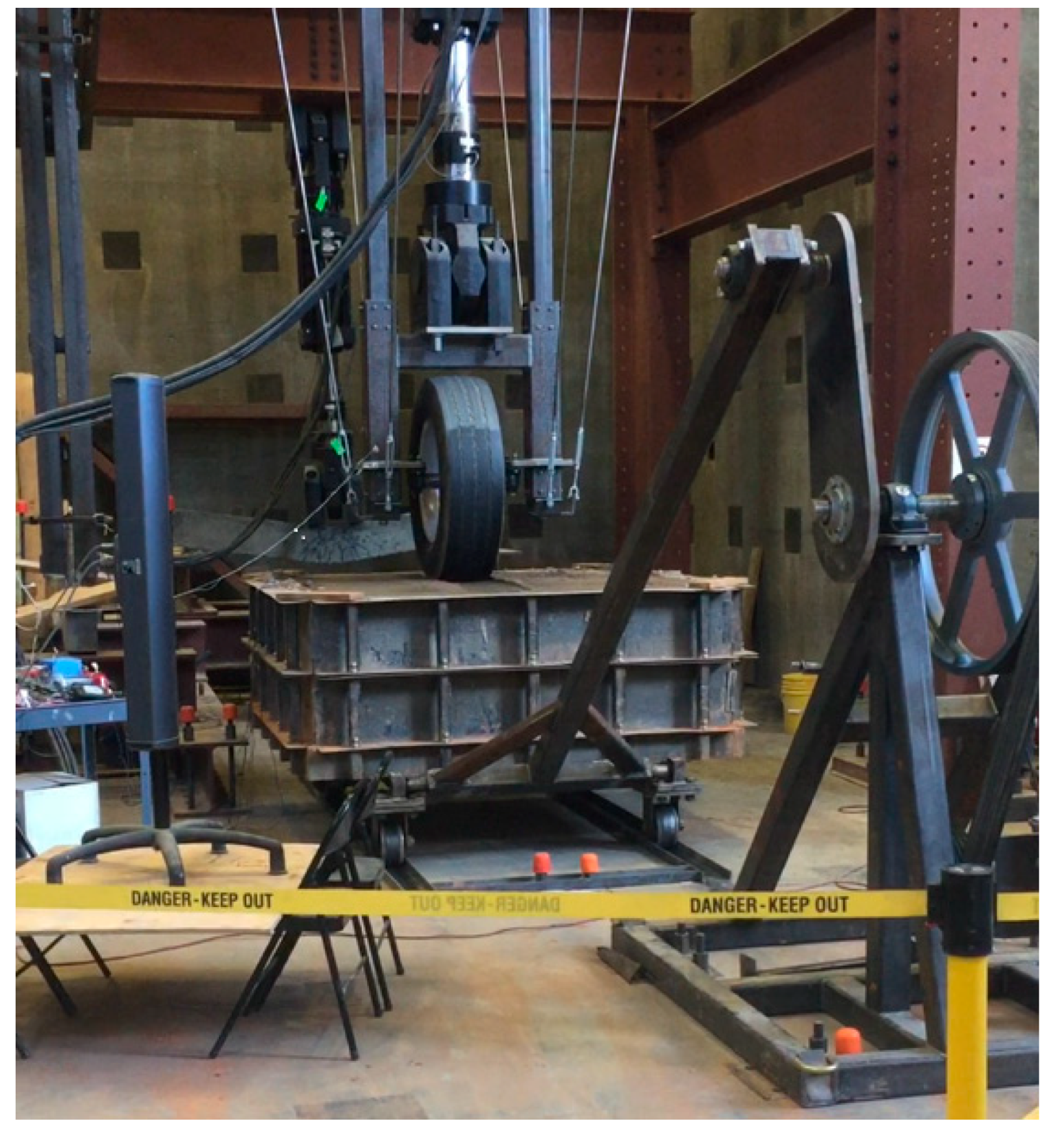
To compare the stress response of the subgrade from RWL to UDL, six different large-scale test specimens were constructed. Test specimens were constructed in a 1.8 m long × 1.8 m wide × 0.6 m deep metal geotechnical box, shown in
Figure 1.
To build each two-layered specimen, 300 mm of subgrade material was prepared at its OMC and compacted using a vibratory plate compactor at the base of the testing apparatus shown in
Figure 1. Once the subgrade layer was deemed appropriately prepared from a series of quality assurance (QA) tests (moisture content, DCP, LWD, sand cone) the GAB was prepared at its OMC. GAB was placed in two 200 mm lifts that were compacted to approximately 150 mm each for a total GAB height of 300 mm. To prevent the boundary effects of the steel, 100 mm of memory foam were placed between the GAB and the walls. Trial testing performed at the beginning of the study determined that the boundary effects of the steel walls were negligible. The specimen was installed in a 2.4 m long track for its wheels and attached to a motor with a crank arm to traverse the specimen under the wheel loading.
4.2. Material Properties
Two different subgrade soils were chosen in this study. The first subgrade soil type was selected from Gordon County in north Georgia while the second subgrade soil type was selected from Hall County in north Georgia. These subgrade soils were selected due to their similar material properties to determine the effect on similar soil types found in north Georgia. They were classified as a high-plasticity silt, MH, according to the Unified Soil Classification System (USCS), and a A-7-5 soil according to the American Association of State Highway and Transportation Officials (AASHTO) [
12]. Other material properties are shown in
Table 2. The unbound aggregate base material was selected as a region-specific material used for the construction of state roadways. The material is commonly referred to as a graded aggregate base or GAB by the state agency and will be referred to as such for the remainder of the document. Several preliminary soil testing was completed in accordance with American Society for Testing and Materials (ASTM) methodology to determine the material’s Optimum Moisture Content, Maximum Dry Density, and CBR for each material type.
Two different geosynthetic products were utilized for testing. An extruded biaxial geogrid and a woven geotextile were investigated to see how geosynthetics modified stress distribution to the top of subgrade layers. These geosynthetic properties are shown in
Table 3.
The focus of the first segment of the study was to evaluate the differences in RWL and UDL on the stress responses in pavement subgrade. To do this instrumentation was needed to accurately measure these differences. A vibrating wire piezometer was installed at the mid-height of the subgrade layer. None of the six testing specimens developed pore water pressure during trafficking. Pressure cells were also used 25 mm below the base–subgrade interface. These cells continuously measured pressure responses from the loading applied during the testing. The measurements give an indication of the vertical stresses experienced by the top of the subgrade layer during trafficking and were used for the data analysis segment of this study.
4.3. Load Application
The load applications were split into two different categories. The first category, the RWL testing procedure, consisted of moving the specimen back and forth under a rolling wheel, which applied the load. To determine the load to apply with the RWL, a finite element analysis was performed on a 200 mm asphalt concrete (AC) layer placed on top of a 300 mm GAB layer. The local state agency that uses the local materials utilized in this study uses a minimum of 200 mm AC regardless of the project design output. To measure the stress distributed to the top of the GAB layer, a 40 kN load was applied to the surface of the FE model. It was determined that approximately 75% of the load was reduced in the AC layer, with 10 kN distributed to the top of the GAB layer. Therefore, for the RWL testing procedure, a load of 10 kN was applied to the top of the specimen with the hydraulic actuator. For RWL, the 10 kN load was held constant while the specimen was tracked back and forth with a motor connected to a crank arm, as shown in
Figure 1. The specimen was crossed approximately 5400 times at a speed of 0.447 m/s. After 5400 passes had been completed, the pressure measurements had stabilized to a constant pressure value at the top of the subgrade. This value was then used for comparisons during data analysis.
Figure 2a shows a schematic of the RWL.
The second load category was the UDL to simulate plate-loading tests. For UDL, a single load was applied with a frequency of 0.15 Hz, or one load per 6.66 s. The actuator applied a single loading and unloading sequence in about 1.0 s with the designated load applied through a large truck tire. This tire had a circular loading area of 250 mm diameter and applied the load to the top of the aggregate base course. Throughout UDL, the geotechnical box was held in a static unmoving position. For this portion of the study, the load of 10 kN was chosen for the testing to match the loading in RWL. An average of the subgrade pressure results for the last 10 load repetitions was used in the analysis segment of this study.
Figure 2b shows a visual for UDL.
4.4. DCP and LWD Tests
To determine the effects of the geosynthetics on the stiffness and strength of the post-trafficked aggregate base and subgrade layers, DCP and LWD tests were conducted before and after traffic-loading application. DCP and LWD readings were split into two different categories. The post-construction readings give an initial reading and were performed after the compaction of each layer. The second category, the post-traffic readings, were taken after the test specimen had been trafficked by the wheel load. Because soil properties like moisture content likely had changed between the post-construction and post-traffic periods, measurements both in the wheel path and outside the wheel path were compared to see the change due to trafficking. Since the measurements taken outside the wheel path had not been trafficked, they were to be designated as post-construction measurements.
The post-construction DCP test categories were taken with 0.3 m (12 inch) penetration depths in both the GAB and subgrade layers. Several measurements were taken in various locations in the specimen and averaged together for a single DCP reading. The LWD was used after test specimen construction to determine the stiffness in terms of an elastic modulus of the underlying layers. The post-construction measurements with the LWD were determined with a 150 mm (5.9-inch) diameter plate in the center of the GAB and subgrade layers due to the thin layer depths.
The second category, denoted as post-traffic measurements, required additional DCP and LWD readings. After trafficking, two DCP readings were taken inside the wheel path to determine the strength change along the depth of the aggregate base layer due to the traffic loading. The LWD was run in the wheel path post-traffic to determine the stiffness increase in the aggregate base and subgrade soils.
5. Results and Analysis
5.1. Effects of Traffic Loading Type
Pressure results for both the large-scale RWL and UDL were measured and recorded in
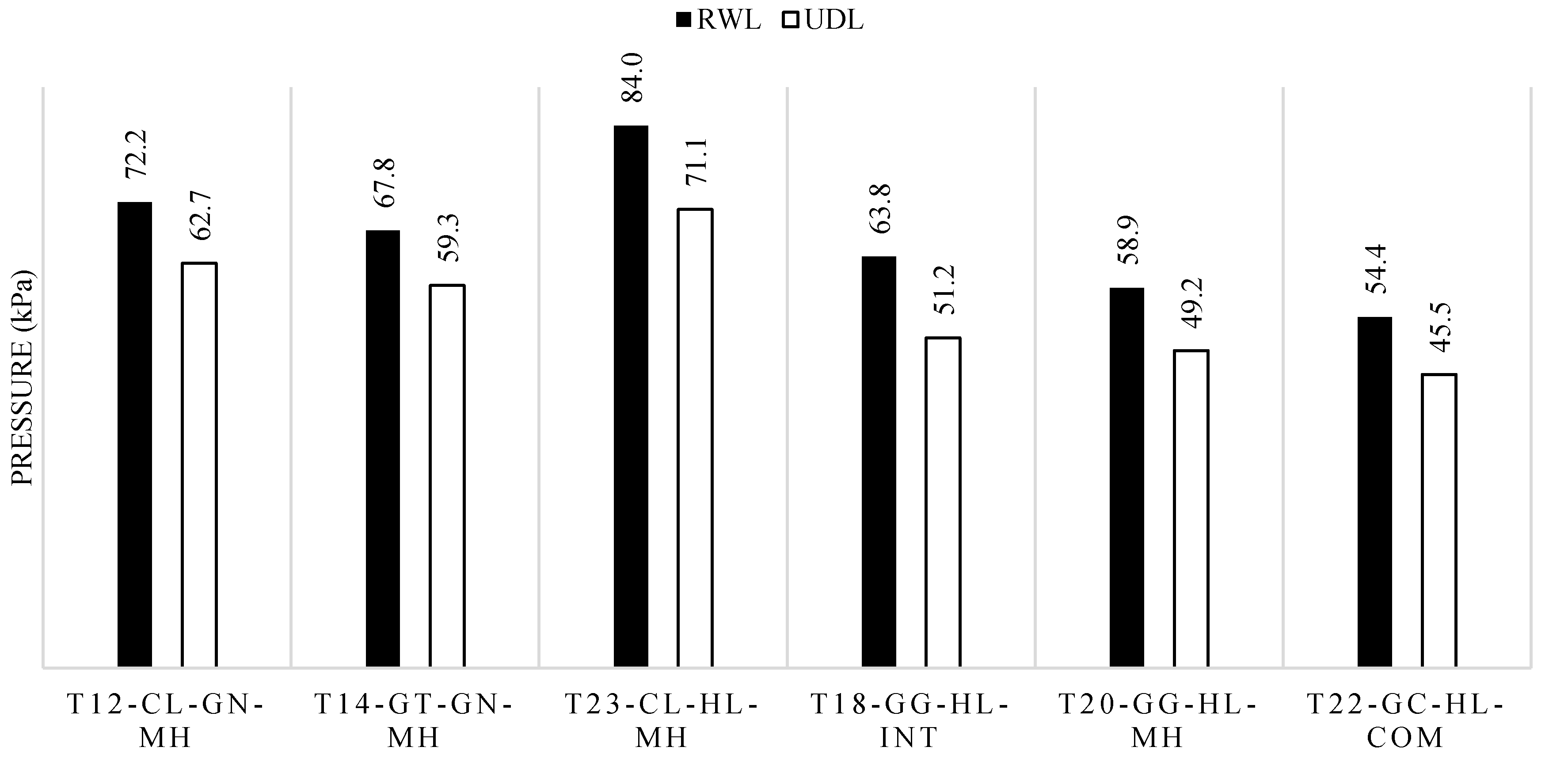
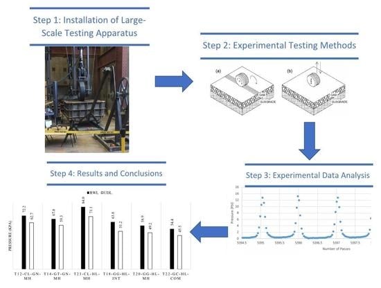
Table 4. To effectively show the difference between the two loading cases, results were plotted in
Figure 3. Results show that, in all six testing series, the pressure measurements were higher in the RWL case than the UDL case in the subgrade soil. In all instances, the pressure experienced in the subgrade of the geosynthetically reinforced test specimens was lower than in the control. This shows that with both RWL and UDL testing, geosynthetic reinforcement provides the benefit of pressure reduction to the subgrade layer. A simple percent difference calculation was performed to calculate the values in
Table 4. Differences ranged from 13.3%–22.0% with an average value of 16.9%. Not only do the results show that there are significant differences between the two loading cases, but they also give an approximate percent difference value that could be used to convert one loading type to another. Given the vast historical PLT data, this conversion value could be used to compare with more recent large-scale RWL testing pressure results to synthesize results further and gain a more holistic viewpoint of geosynthetic influence on pavement subgrades.
5.2. Stiffness and Strength Improvement of Geosynthetics-Reinforced Pavement Foundation
The test results and data analysis shown herein are categorized into the two testing methods: LWD results and DCP results. The mechanical properties (stiffness and strength) in a pavement foundation are very influential on pavement responses and this analysis investigates how a geotextile and a geosynthetic combination affects these properties.
5.2.1. LWD Test Results
The LWD results indicate the stiffness of the pavement foundation. The post-construction values illustrate that the modulus of the aggregate base layer is consistent with each test specimen.
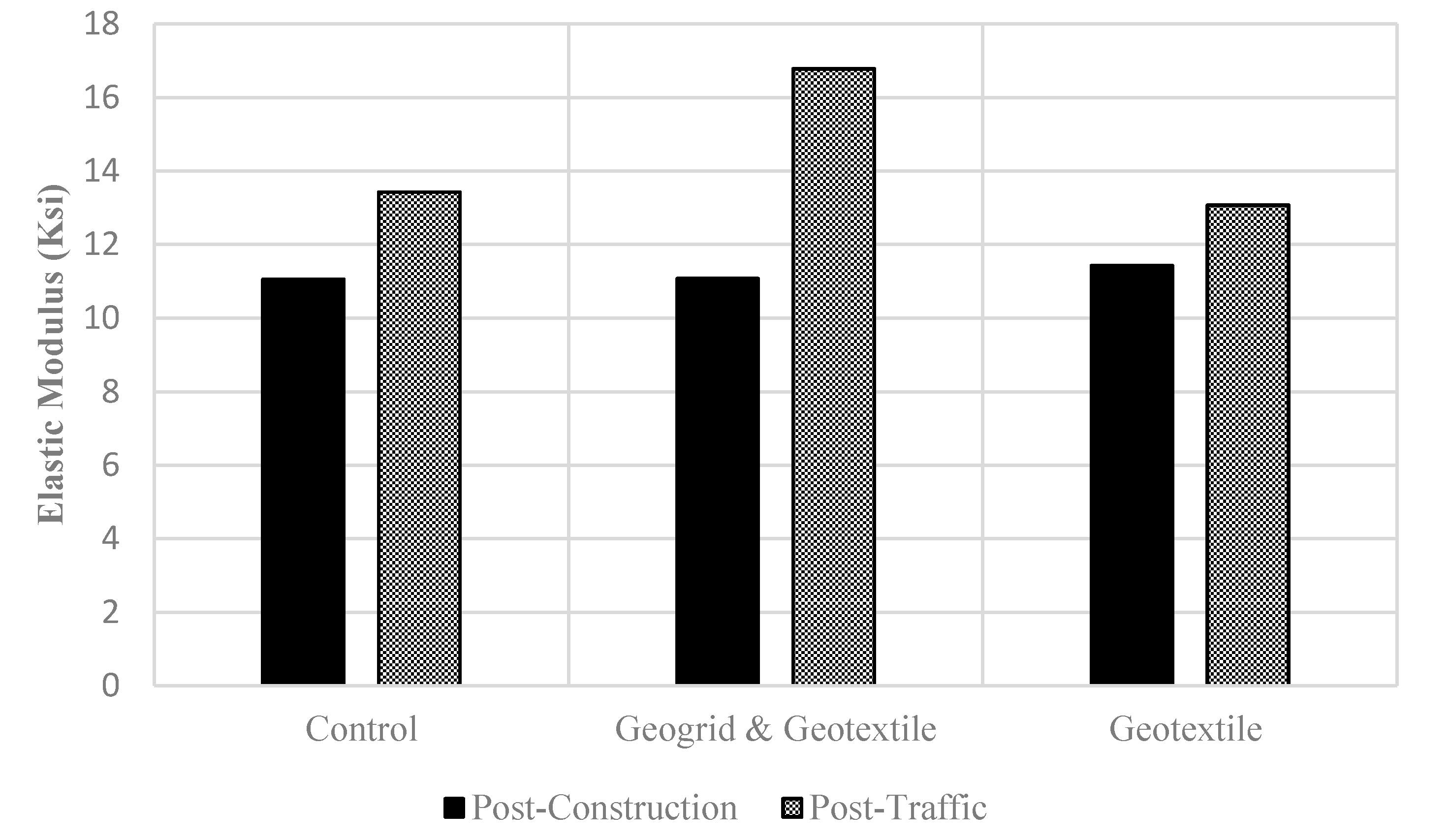
Figure 4 shows that the elastic modulus of the aggregate base layer increases after trafficking in all three test sections. The inclusion of the geosynthetic has little influence on the stiffness of the upper areas of the aggregate base layer post-construction because all three specimens had similar modulus values.
In all cases, the modulus of the aggregate base layer increases from the untrafficked (post-construction) to the trafficked areas of the specimen due to the densification of the material from the RWLs. It is noted that using both the geogrid and geotextile in conjunction increased the modulus 51%. These results corroborate the strength trends found by Jersey and Tingle [
8]. It seems that this stiffening phenomenon promotes better load distribution, resulting in a reduction in the pressure exhibited in geosynthetically reinforced pavements.
5.2.2. DCP Test Results
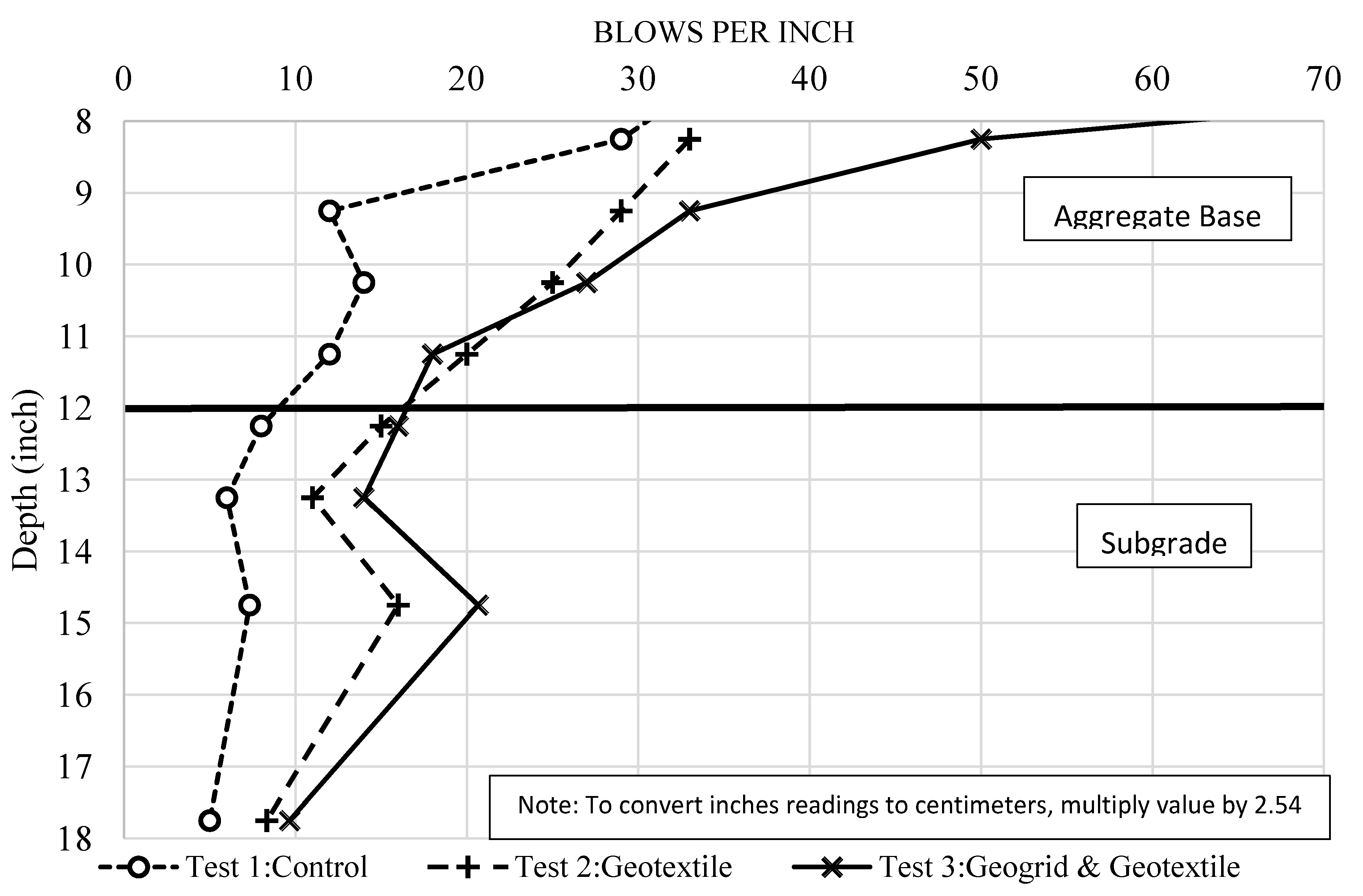
The measurements shown in
Figure 5 represent the post-traffic DCP readings taken from inside the wheel path. The number of blows required to penetrate one inch of the pavement layers is presented as the circular datapoints. The DCP results clearly show the strength of the pavement layers along the depth of the specimen. The points further to the right indicate a stronger layer because they require more blows to penetrate each inch. Conversely, the points further to the left indicate a weaker layer. The horizontal black line indicates the base subgrade interface and the location where the geotextile was placed for Test 2 and 3.
Several trends are found in the DCP results. Comparing the control (Test 1), and the geotextile-reinforced (Test 2) test specimen illustrates that the geotextile effectively strengthens about 10 cm of the GAB layer located directly on top of it with its friction. Both test sections show about the same strength (same number of blows required to penetrate one inch) at the 10 cm depth but as the depth increases, the geosynthetic stiffens the base course, shown with a line further to the right for the geotextile specimen. This is determined by the higher number of blows required compared to the control. Thirty centimeters of GAB layer is considered a thick base material and while geotextiles do provide some benefit in strengthening the subgrade, their influence is likely unable to strengthen the entire depth of thick base course sections. These results provide some insight into why geotextiles can decrease the pressure distributed to the subgrade material when placed at the base–subgrade interface.
Comparisons are made between Test 3, the geogrid and geotextile combination, versus the control DCP measurements.
Figure 5 shows that the aggregate base course is significantly stronger than the control readings. The area between the two geosynthetics shows a combination of an interlock effect from the geogrid and a friction effect from the geotextile, which creates a dual strengthening effect. This area has a higher strength than both the standalone geotextile and control test sections, showing that the geogrid can strengthen the base material under it, creating an additive strengthening effect with the geotextile.
The DCP and LWD measurements of the GAB layer have several similarities. For post-traffic readings, both the stiffness and strength of the layer was generally highest for the geogrid and geotextile specimen (Test 3), second highest for the geotextile-reinforced specimen (Test 2), and lowest for the control test section (Test 1). While the general layer trends were similar, there were a few differences between the two measurements. Because the DCP was able to measure strength along the depth, it showed that, for the geotextile-reinforced specimen, the strength was equal to the control at 20.3 mm below the surface, with a 10.1 cm stiffened base above the geotextile. The LWD test for the base material only produced one measurement and showed that the layer as a whole was stiffer than the control test specimen.
6. Conclusions
Pressure comparisons between the large-scale RWL and the UDL show a trend of higher stresses (16.9% on average) for the RWL tests;
The significant pressure differences are likely due to the complex stresses from RWL. RWL tests more accurately capture the complicated stress states in the subgrade than the simpler PLT procedure;
The use of a geotextile at the interface and the geogrid at mid-height both stiffens and strengthens the aggregate base course after trafficking when compared to the control test specimen. This is likely one of the causes for the reduction in stress transferred to the subgrade and bottom of the aggregate base layer when using geosynthetics;
The use of a woven geotextile at the interface and an extruded biaxial geogrid at the mid-height of the aggregate base course increased the stiffness of the post-trafficked aggregate base course 51% more than the control case;
The DCP readings showed that the geogrid and geotextile case strengthened the base significantly more than the control and geotextile alone case. The single geotextile case stiffened the bottom 10.2 cm of the base.
Author Contributions
The authors confirm contribution to the paper as follows: study conception and design: J.W., S.S.K.; data collection: J.W., S.S.K.; analysis and interpretation of results: J.W., S.S.K., and B.K.; draft manuscript preparation: J.W., S.S.K., B.K. All authors have read and agreed to the published version of the manuscript.
Funding
The work presented in this paper is part of a research project (RP 16-11) sponsored by the Georgia Department of Transportation. The contents of this paper reflect the views of the authors, who are solely responsible for the facts and accuracy of the data, opinions, and conclusions presented herein. The contents may not reflect the views of the funding agency or other individuals.
Acknowledgments
The large scale pavement testing was carried out at the University of Georgia (UGA). It was fully supported by UGA College of Engineering and GDOT.
Conflicts of Interest
Authors declare no conflict of interests. The funders had no role in the design of the study; in the collection, analyses, or interpretation of data, in the writing of the manuscript, or in the decision to publish the results.
References
- Douglas, R.A. Repeated-load behaviour of geosynthetic-built unbound roads. Can. Geotech. J. 1997, 34, 197–203. [Google Scholar] [CrossRef]
- Kelly, D.; Fairfield, C.; Sibbald, A. Geosynthetics for the improvement of unpaved roads. Highw. Transp. 1995, 42, 13–15. [Google Scholar]
- Gregory, G.H.; Bang, S. Design of flexible pavement subgrades with geosynthetics. In Proceedings of the 30th Symposium on Engineering Geology and Geotechnical Engineering, Boise, Idaho, 1 January 1994; pp. 569–582. [Google Scholar]
- Douglas, R.A.; Valsangkar, A.J. Unpaved geosynthetic-built resource access roads: Stiffness rather than rut depth as the key design criterion. Geotext. Geomembr. 1992, 11, 45–59. [Google Scholar] [CrossRef]
- Bauer, G.E.; El Halim, A.A. The performance of geogrid reinforced road bases. Constr. Build. Mater. 1987, 1, 71–75. [Google Scholar] [CrossRef]
- Ashmawy, A.K.; Bourdeau, P.L. Geosynthetic-reinforced soils under repeated loading: A review and comparative design study. Geosynth. Int. 1995, 2, 643–678. [Google Scholar] [CrossRef]
- Kiptoo, D.; Aschrafi, J.; Kalumba, D.; Lehn, J.; Moormann, C.; Zannoni, E. Laboratory Investigation of a Geosynthetic Reinforced Pavement Under Static and Dynamic Loading. J. Test. Eval. 2016, 45, 76–84. [Google Scholar] [CrossRef]
- Tingle, J.S.; Jersey, S.R. Cyclic plate load testing of geosynthetic-reinforced unbound aggregate roads. Transp. Res. Rec. 2005, 1936, 60–69. [Google Scholar] [CrossRef]
- Abu-Farsakh, M.Y.; Chen, Q. Evaluation of geogrid base reinforcement in flexible pavement using cyclic plate load testing. Int. J. Pavement Eng. 2011, 12, 275–288. [Google Scholar] [CrossRef]
- Wright, J.; Kim, S.S. Effect of Geosynthetics on Strength and Stiffness Improvement of Pavement Foundation Post-Trafficking. In Proceedings of the 2019 Geosynthetics Conference, Houston, TX, USA, 10–13 February 2019. [Google Scholar]
- Kim, S.S.; Frost, D.; Durham, S.; Chorzepa, M.; Wright, J.; Hanumasagar, S. Development of Geosynthetic Design and Construction Guidelines for Pavement Embankment Construction in North Georgia; Final Report #FHWA-GA-19-1611; Georgia Department of Transporation: Atlanta, GA, USA, 2019. [Google Scholar]
- Williams, S.; Wright, J.; Hanumasagar, S.; Kim, S.; Frost, J. Large-Scale and Bench-Scale Test Systems for Assessing Impact of Geogrids on Pavements Founded on Problematic Soils. J. Test. Eval. 2018, 47, 1967–1981. [Google Scholar] [CrossRef]
© 2020 by the authors. Licensee MDPI, Basel, Switzerland. This article is an open access article distributed under the terms and conditions of the Creative Commons Attribution (CC BY) license (http://creativecommons.org/licenses/by/4.0/).
