Comparative Study of Seismic Design and Performance of OMRF Building Using Indian, British, and European Codes


Abstract
:
1. Introduction
1.1. General Overview
1.2. A Brief on Buildings in India
1.3. Past Studies and Codes
1.4. Problem Statement
1.5. Significance and Methodology
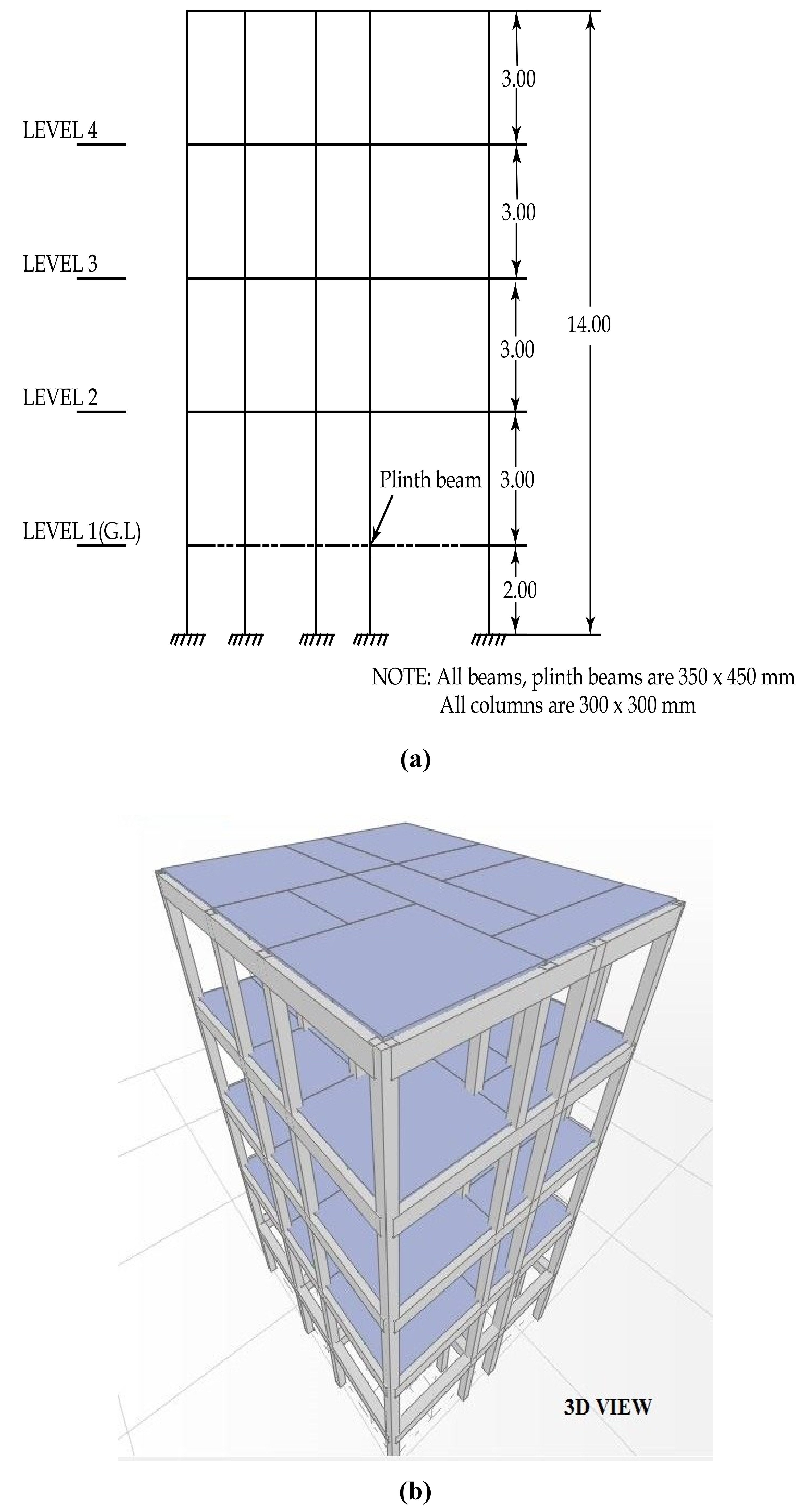
2. Model and Design
2.1. Loading
- a.
- 1.5 (Dead Load + Imposed Load)
- b.
- 1.2 (Dead Load + Imposed Load ± Earthquake Load)
- c.
- 1.5 (Dead Load ± Earthquake Load)
- d.
- 0.9 Dead Load ± 1.5 Earthquake Load
2.2. Reinforcement
2.3. Methodology
2.4. Properties of Hinges
3. Results and Discussion
4. Conclusions
- For the WoEQ loading condition, the amount of steel required to comply with the Indian code is 40.6% and 35.1% more than the British, and Euro code, respectively. Further, for buildings designed with WiEQ, the amount for steel required to comply with the Indian code is 66.5% and 43.5% more than the British code, and European code, respectively. This may be due to various safety factors applied on materials, ductility provisions, and the minimum criteria of reinforcement in the various codes.
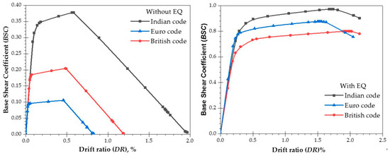
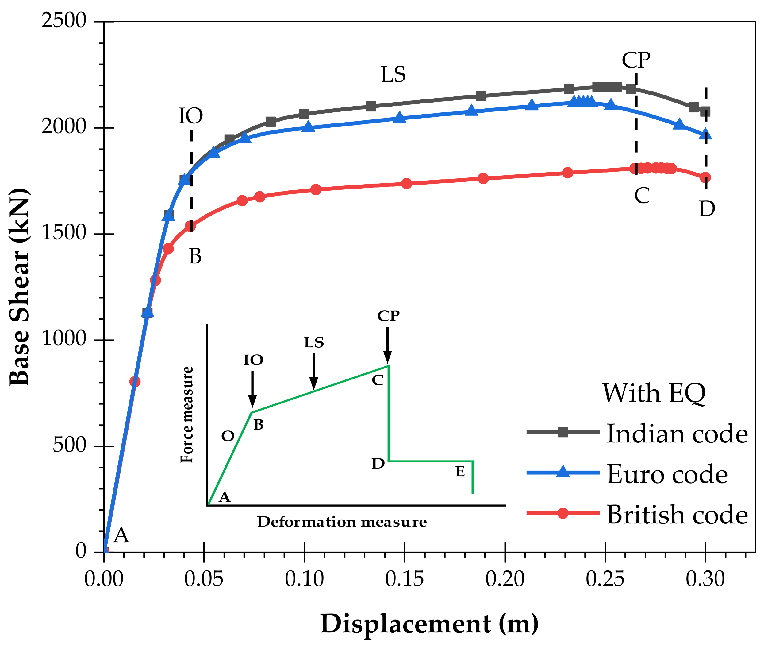
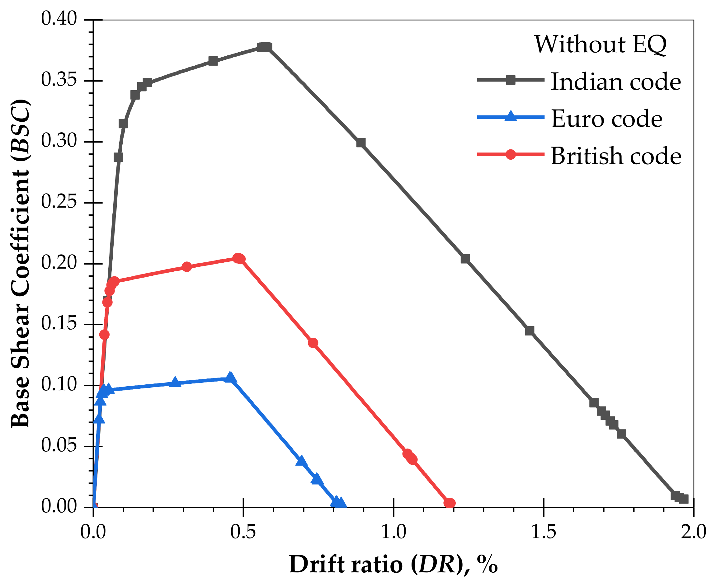
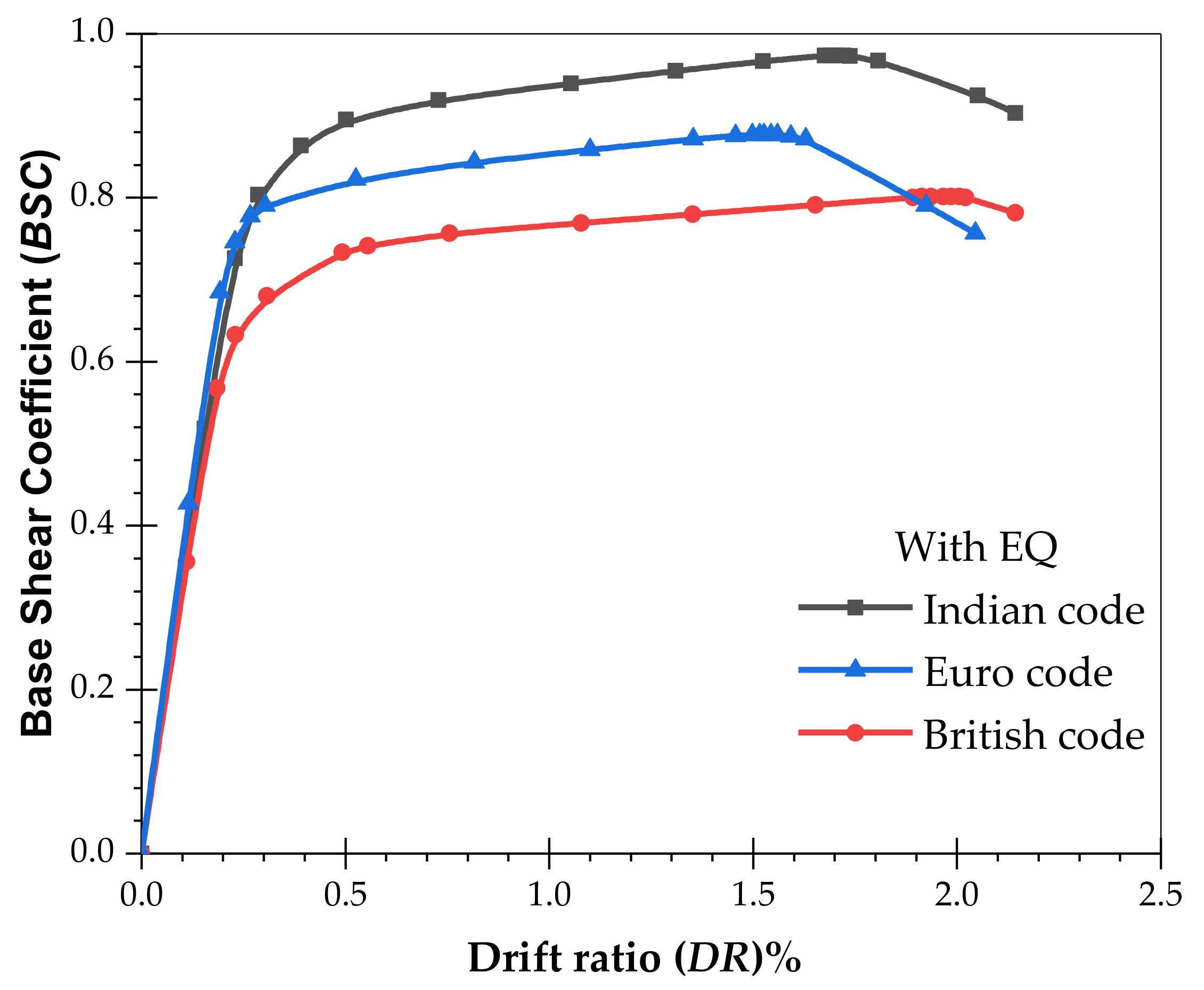
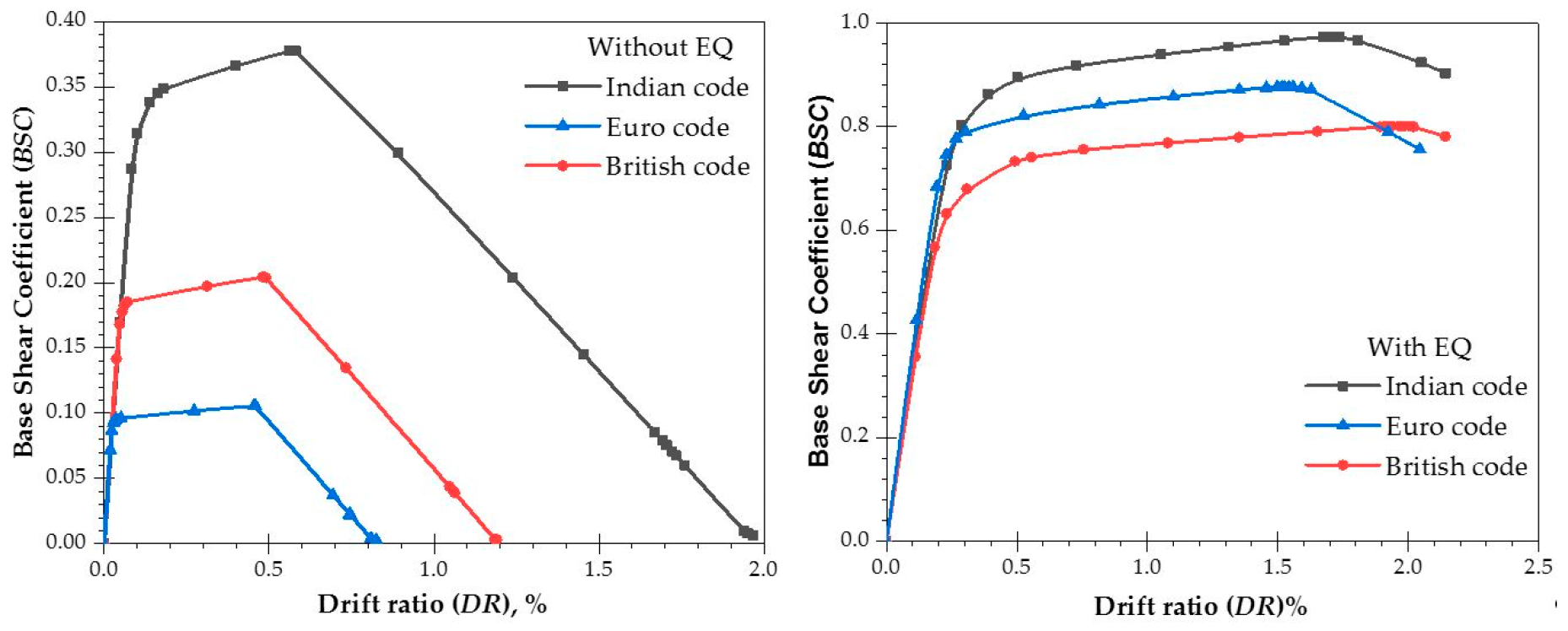
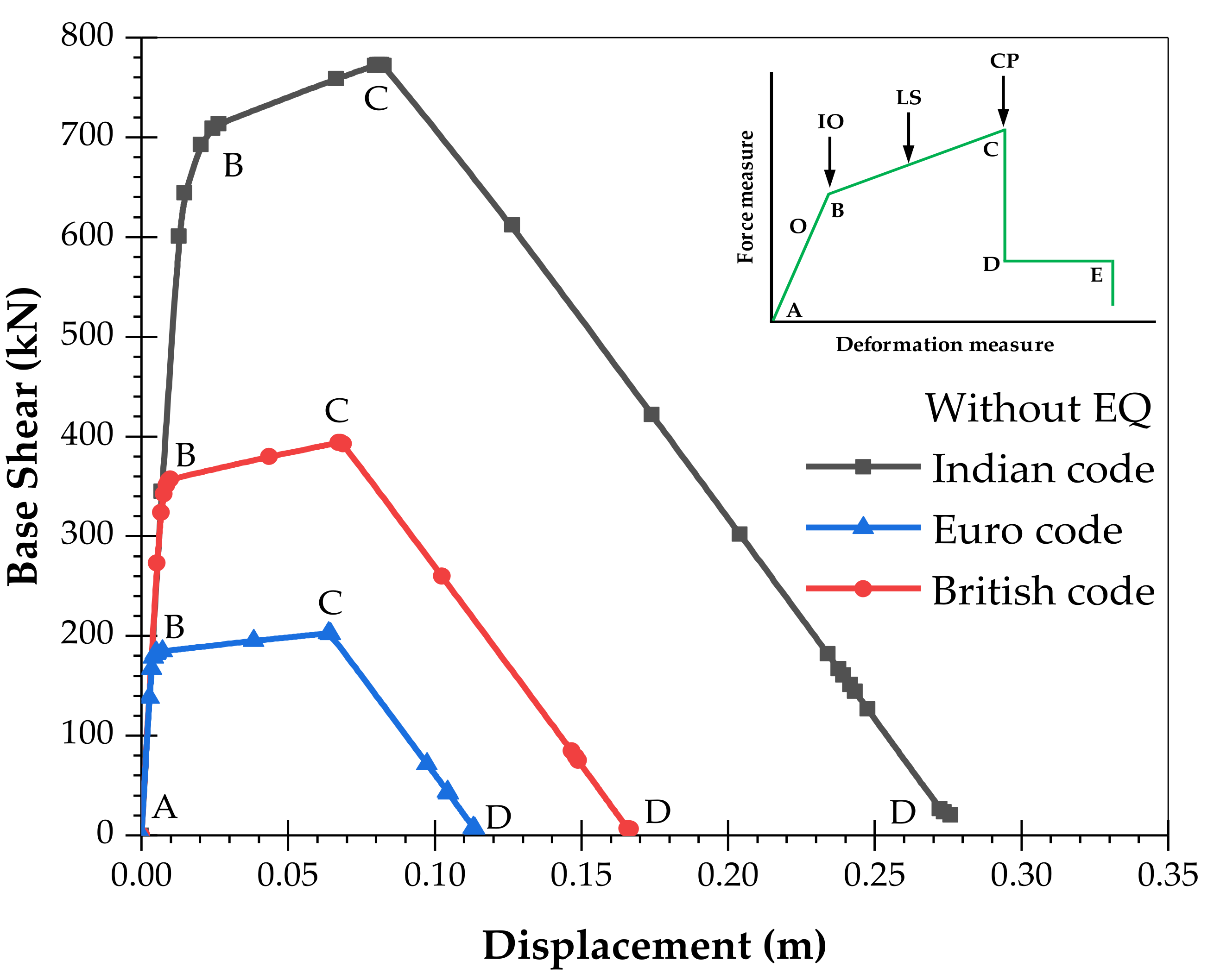
- The pushover analysis results show that buildings designed in accordance with the Indian code perform significantly better in a seismic environment compared with the British and European codes. In the case of WoEQ loading, there is an increase in the load capacity of 95% and 279%, and for WiEQ loading, the corresponding increases are about 17% and 23.42% over the British code, and Euro code, respectively. Further, for WoEQ loading case, the Indian code gives a 19% and 26% increase in displacement capacity compared to the British code, and Euro code, respectively. Whereas, for WiEQ loading, the increase is about 11.68% w.r.t the Euro code and is almost comparable w.r.t the British code.
- It is also observed that for a large displacement capacity without strength and stiffness degradation, the Indian code provides a 19% and 26% increase in displacement capacity compared to the British code, and Euro code, respectively for WoEQ loading.
- The study also concludes that, for the same level of hazard at different places on earth, one should have a uniform design and detailing provisions.
Author Contributions
Funding
Acknowledgments
Conflicts of Interest
References
- Jain, S.K.; Lettis, W.R.; Murty, C.V.R.; Bardet, J.-P. Bhuj, India Earthquake of January 26, 2001. Earthq. Spectra 2002, 18 (Suppl. A), 398. [Google Scholar]
- Kumar, S.L. Theory of Earthquake Resisting Design with a Note on Earthquake Resisting Construction in Baluchistan; Punjab Engineering Congress: Punjab, Pakistan, 1993; pp. 154–189. [Google Scholar]
- National Disaster Management Authority (NDMA). Seismic Retrofitting of Deficient Buildings and Structures in India Report 2014. Available online: https://ndma.gov.in/images/guidelines/retrofitting-guidelines.pdf (accessed on 15 February 2015).
- Jain, S.K. Earthquake safety in India: Achievements, challenges and opportunities. Bull. Earthq. Eng. 2016, 14, 1337–1436. [Google Scholar] [CrossRef]
- Indian Standard. ‘IS-456. 2000’ Plain and Reinforced Concrete-Code of Practice; Bureau of Indian Standards: New Delhi, India, 2000. [Google Scholar]
- Indian Standard. ‘IS 1893 (PART-I)’ Criteria for Earthquake Resistant Design of Structure, General Provisions and Buildings; Bureau of Indian Standards: New Delhi, India, 2002. [Google Scholar]
- National Institute of Disaster Management (NIDM). Rapid Visual Screening of Reinforce Concrete Buildings Report 2015. Available online: https://nidm.gov.in/PDF/safety/earthquake/link10.pdf (accessed on 15 February 2015).
- National Disaster Management Authority (NDMA). Seismic Vulnerability Assessment of Building Types in India Report 2013. Available online: https://ndma.gov.in/images/disaster/earthquake/ExecutiveSummaryReport.pdf (accessed on 15 February 2015).
- Sinha, R.; Adarsh, N. A postulated earthquake damage scenario for Mumbai. ISET J. Earthq. Technol. 1999, 36, 169–183. [Google Scholar]
- Gulati, B. Earthquake Risk Assessment of Buildings: The Applicability of HAZUS in Dehradun, India. Master’s Thesis, Indian Institute of Remote Sensing, Dehradun, India, 2006. [Google Scholar]
- Prasad, J.S.R.; Singh, Y.; Kaynia, A.M.; Lindholm, C. Socioeconomic clustering in seismic risk assessment of urban housing stock. Earthq. Spectra 2009, 25, 619–641. [Google Scholar] [CrossRef]
- Subramanian, N. Design of Reinforced Concrete Structures; Oxford University Press: Oxford, UK, 2013. [Google Scholar]
- Ministry of Finance, Department of Expenditure, Government of India. Available online: http://finmin.nic.in/the_ministry/dept_expenditure/miscellaneous/hracca.pdf (accessed on 15 February 2015).
- Office of the Registrar General and Census Commissioner, India. 2011. Available online: http://www.censusindia.gov.in (accessed on 4 April 2014).
- Humar, J.M.; Lau, D.; Pierre, J.R. Performance of buildings during the 2001 Bhuj earthquake. Can. J. Civ. Eng. 2001, 28, 979–991. [Google Scholar] [CrossRef]
- Ghosh, S.K. Observations from the Bhuj earthquake of January 26, 2001. Pci J. 2001, 46, 34–43. [Google Scholar] [CrossRef]
- Lopes, M. Evaluation of the seismic performance of an old masonry building in Lisbon. In Proceedings of the 11th World Conference in Earthquake Engineering, Acapulco, Mexico, 23–28 June 1996. No. 1484. [Google Scholar]
- Rai, D.C.; Goel, S.C. Seismic strengthening of unreinforced masonry piers with steel elements. Earthq. Spectra 1996, 12, 845–862. [Google Scholar] [CrossRef]
- Azevedo, J.; Sincraian, G.; Lemos, J.V. Seismic behavior of blocky masonry structures. Earthq. Spectra 2000, 16, 337–365. [Google Scholar] [CrossRef]
- Erberik, M.A. Seismic risk assessment of masonry buildings in Istanbul for effective risk mitigation. Earthq. Spectra 2010, 26, 967–982. [Google Scholar] [CrossRef]
- Zimmermann, T.; Strauss, A.; Wendner, R. Old masonry under seismic loads: Stiffness identification and degradation. In Proceedings of the Structures Congress 2011, Las Vegas, NV, USA, 14–16 April 2011; pp. 1736–1747. [Google Scholar]
- Zhao, H.; Zhang, Y. Seismic Performance Analysis of the Existing Masonry Structure of Beijing Rural Suburbs. In Proceedings of the International Conference on Civil Engineering and Urban Planning 2012, Yantai, China, 18–20 August 2012; pp. 548–552. [Google Scholar]
- Wallace, J.W. Evaluation of UBC-94 provisions for seismic design of RC structural walls. Earthq. Spectra 1996, 12, 327–348. [Google Scholar] [CrossRef]
- Otani, S. RC building damage statistics and SDF response with design seismic forces. Earthq. Spectra 1999, 15, 485–502. [Google Scholar] [CrossRef]
- Lim, C.L.; Li, B.; Pan, T.C. Seismic performances of reinforced concrete frames with wall-like columns. IES J. Part A Civ. Struct. Eng. 2009, 2, 126–142. [Google Scholar] [CrossRef]
- Ghavamian, S.; Jason, L.; Bonenfant, J. Damage mechanics applied to the seismic behavior of concrete structures. Eur. J. Environ. Civ. Eng. 2010, 14, 839–854. [Google Scholar] [CrossRef]
- Wallace, J.W.; Massone, L.M.; Bonelli, P.; Dragovich, J.; Lagos, R.; Lüders, C.; Moehle, J. Damage and implications for seismic design of RC structural wall buildings. Earthq. Spectra 2012, 28, S281–S299. [Google Scholar] [CrossRef]
- Massone, L.M.; Bonelli, P.; Lagos, R.; Lüders, C.; Moehle, J.; Wallace, J.W. Seismic design and construction practices for RC structural wall buildings. Earthq. Spectra 2012, 28, S245–S256. [Google Scholar] [CrossRef]
- Nardone, F.; Verderame, G.M.; Prota, A.; Manfredi, G. Comparative Analysis on the Seismic Behavior of Combined RC-Masonry Buildings. J. Struct. Eng. 2010, 136, 1483–1496. [Google Scholar] [CrossRef]
- Bayraktar, A.; Altunisik, A.C.; Türker, T.; Karadeniz, H.; Erdogdu, S.; Angin, Z.; Özsahin, T.S. Structural performance evaluation of 90 RC buildings collapsed during the 2011 Van, Turkey, earthquakes. J. Perform. Constr. Facil. 2013, 29, 04014177. [Google Scholar] [CrossRef]
- Itti, S.V.; Pathade, A.; Karadi, R.B. A Comparative Study on Seismic Provisions Made in Indian and International Building Codes for RC Buildings. 2014. Available online: https://www.sefindia.org/forum/files/a_comparative_study_on_seismic_provisions_made_in_indian_and_international_building_codes_for_rc_buildings_107.pdf (accessed on 5 June 2019).
- International Code Council (ICC). International Building Code 2016; ICC: Washington, DC, USA, 2006. [Google Scholar]
- Benavent-Climent, A.; Zahran, R. Seismic evaluation of existing RC frames with wide beams using an energy-based approach. Earthq. Struct. 2010, 1, 93–108. [Google Scholar] [CrossRef]
- Chaulagain, H.; Rodrigues, H.; Jara, J.; Spacone, E.; Varum, H. Seismic response of current RC buildings in Nepal: A comparative analysis of different design/construction. Eng. Struct. 2013, 49, 284–294. [Google Scholar] [CrossRef]
- Li, Z.; He, M.; Li, M.; Lam, F. Damage assessment and performance-based seismic design of timber-steel hybrid shear wall systems. Earthq. Struct. 2014, 7, 101–117. [Google Scholar] [CrossRef]
- Ali, Q.; Khan, A.N.; Ashraf, M.; Ahmed, A.; Alam, B.; Ahmad, N.; Javed, M.; Rahman, S.; Fahim, M.; Umar, M. Seismic performance of stone masonry buildings used in the Himalayan Belt. Earthq. Spectra 2013, 29, 1159–1181. [Google Scholar] [CrossRef]
- Kaur, K.; Singh, J. A Review on Comparison of Seismic Behavior of RC Structures Using Various Codes. Int. J. Agric. Environ. Biotechnol. 2017, 10, 703–707. [Google Scholar] [CrossRef]
- Ramanjaneyulu, K.; Novák, B.; Sasmal, S.; Roehm, C.; Lakshmanan, N.; Iyer, N.R. Seismic performance evaluation of exterior beam-column sub-assemblages designed according to different codal recommendations. Struct. Infrastruct. Eng. 2013, 9, 817–833. [Google Scholar] [CrossRef]
- Ng, C.K.; Loo, S.W.; Bong, Y.P. Reinforced concrete beams at ultimate flexural limit state: Comparison of BS 8110 and Eurocode 2. In Proceedings of the 6th Asia-Pacific Structural Engineering and Construction Conference (APSEC 2006), Kuala Lumpur, Malaysia, 5–6 September 2006; pp. 56–67. [Google Scholar]
- British Standard Institution. Structural Use of Concrete: Part 1-Code of Practice for Design and Construction; BS 8110: Part 1: 1997; British Standard Institution: London, UK, 1998. [Google Scholar]
- EN 1992-1-2. Eurocode 2: Design of Concrete Structures, Part 1-2: General Rules–Structural Fire Design 2002; European Committee for Standardization: Brussels, Belgium, 2004. [Google Scholar]
- EN 1992-1-1. Eurocode 2: Design of Concrete Structures–Part 1-1: General Rules and Rules for Buildings; European Committee for Standardization: Brussels, Belgium, 2004. [Google Scholar]
- Bashir, S. Design of Short Columns According to ACI 318-11 and BS 8110-97: A Comparative Study Based on Conditions in Nigeria. Ph.D. Thesis, Near East University, North Cyprus, Turkey, 2014. [Google Scholar]
- BS EN 1998-1. Eurocode 8: Design Provisions for Earthquake Resistance of Structures, Part 1: General Rules, Seismic Actions and Rules for Buildings, European Committee for Standardization: Brussels, Belgium, 2004.
- Building Seismic Safety Council. NEHRP Handbook for the Seismic Evaluation of Existing Buildings; FEMA 178; Building Seismic Safety Council: Washington, DC, USA, 1992. [Google Scholar]
- Building Seismic Safety Council. Handbook for the Seismic Evaluation of Buildings; FEMA 310; Building Seismic Safety Council: Washington DC, USA, 1998. [Google Scholar]
- Applied Technology Council. Evaluating the Seismic Resistance of Existing Buildings; Report ATC-14; Applied Technology Council: Redwood City, CA, USA, 1987. [Google Scholar]
- Applied Technology Council. NEHRP Guidelines for the Seismic Rehabilitation of Buildings; FEMA 273; Building Seismic Safety Council: Washington, DC, USA, 1997. [Google Scholar]
- National Institute of Building Sciences. Earthquake Loss Estimation Methodology, HAZUS-99 Service Release 2 (SR2) Technical Manual; Federal Emergency Management Agency: Washington, DC, USA, 2002.
- Turnsek, V.; Tercelj, S.; Sheppard, P.F.; Tomazevic, M. The seismic resistance of stone-masonry walls and buildings. In Proceedings of the Sixth European Conference on Earthquake Engineering, Dubrovnik, Yugoslavia, 18–22 September 1978; pp. 255–262. [Google Scholar]
- Tomaževič, M.; Klemenc, I. Seismic behaviour of confined masonry walls. Earthq. Eng. Struct. Dyn. 1997, 26, 1059–1071. [Google Scholar] [CrossRef]
- American Society of Civil Engineers. Prestandard and Commentary for the Seismic Rehabilitation of Buildings; FEMA 356; Federal Emergency Management Agency: Washington, DC, USA, 2000.
- Hasha, G.; Raza, S.A. Seismic Vulnerability of RC building with and without soft storey effect using Pushover Analysis. Int. J. Mod. Eng. Res. 2014, 4, 32–47. [Google Scholar]
- ACI Committee 318. Building Code Requirements for Structural Concrete (ACI 318-02) and Commentary (ACI 318R-02); American Concrete Institute: Farmington Hills, MI, USA, 2002. [Google Scholar]
- IS 13920: 1993 (Reaffirmed 2003). Ductile Detailing of Reinforced Concrete Structures Subjected to Seismic Forces: Code of Practice; Bureau of Indian Standards: New Delhi, India, 2000. [Google Scholar]


| 1) Type of Structure | Multi-storey rigid jointed space frame |
| 2) Seismic Zone of India | V |
| 3) Number of stories | (G+3) |
| 4) Imposed load including Floor Finishes | 2.5 kN/m2 (52.25 lbf/ft2) |
| 5) Outer Brick wall load (due to 230 mm) | 13 kN/m (891 lb/ft) |
| 6) Inner Brick wall/Partition load (due to 110 mm) | 6 kN/m (411 lb/ft) |
| 7) Depth of slab | 120 mm (4.7’’) |
| 8) Materials | M25 concrete and Fe415 steel |
| 9) Modulus of elasticity of concrete | 2.10 × 10⁵ N/mm2 (4.40 × 10⁹ lb/ft2) |
| Code | Concrete in Flexure or Axial Load | Concrete in Shear | Concrete in Bond | Reinforcement Steel |
|---|---|---|---|---|
| BS 8110-1997 [40] | 1.50 | 1.25 | 1.40 | 1.15 |
| EN 1992-2004 [42] | 1.50 | 1.50 | 1.50 | 1.15 |
| IS 456-2000 [5] | 1.50 | 1.50 | 1.50 | 1.15 |
| Code | Dead Load (DL) | Live Load (LL) |
|---|---|---|
| BS 8110-1997 [40] | 1.40 | 1.60 |
| EN 1992-2004 [42] | 1.35 | 1.50 |
| IS 456-2000 [5] | 1.50 | 1.50 |
| Particulars | Values |
|---|---|
| 1. Damping Ratio (concrete) | 5% |
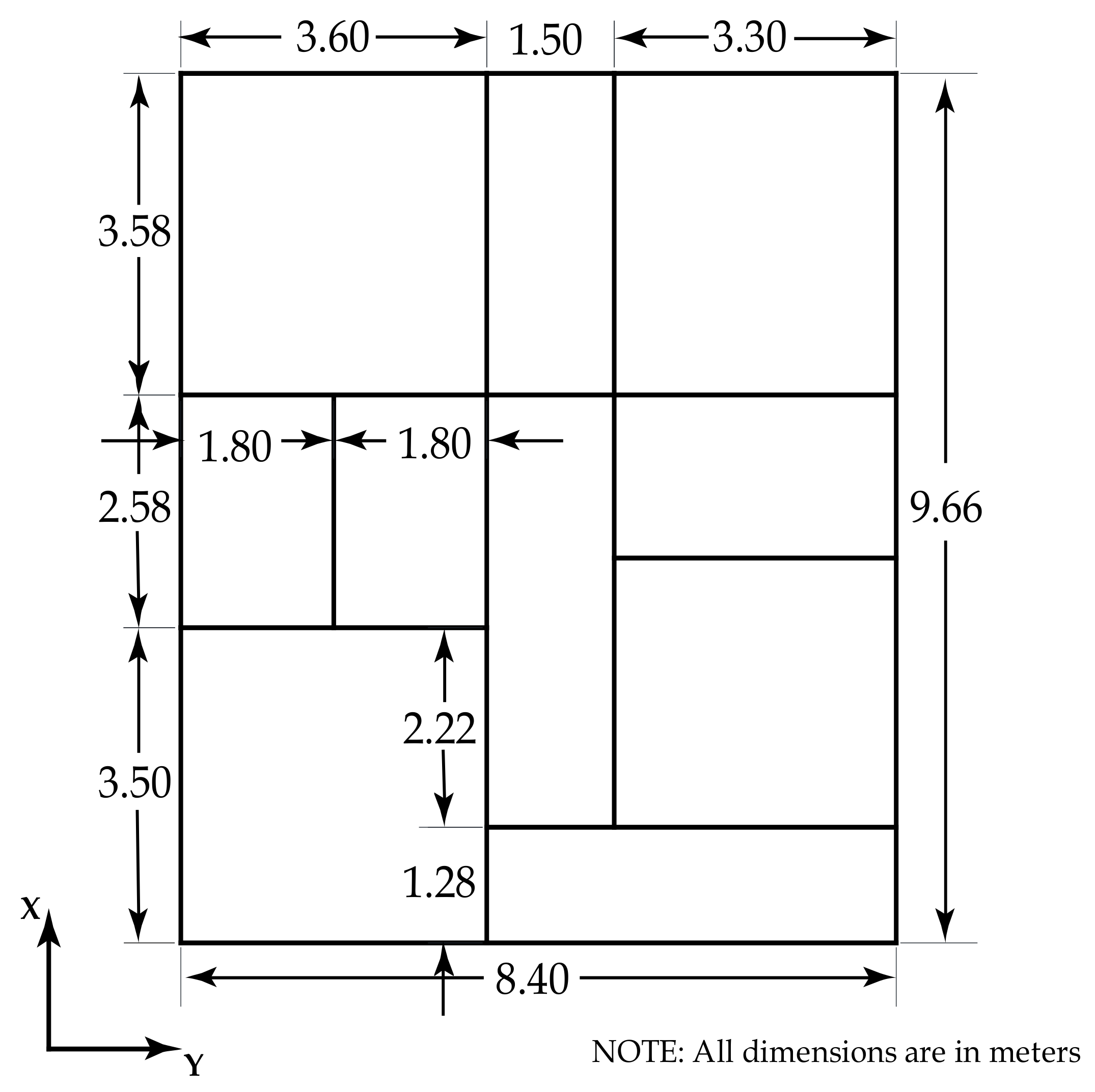
| 2. Seismic coefficients = 0.36, = 1, = 3 (OMRF), = 2.5 T= 0.09h/√d Tx = 0.09(14/√8.44) = 0.4337 sec Tz = 0.09(14/√9.66) = 0.4054 sec | 0.15 |
| Members | BS 8110-1997 [40] | EC 2 [41] | IS 456-2000 [5] | |||
|---|---|---|---|---|---|---|
| Min. % | Max. % | Min. % | Max. % | Min. % | Max. % | |
| Beam | 0.13 | 4.00 | 0.30 | 4.00 | - | 4.00 |
| Column | 0.40 | 6.00 | 0.30 | 8.00 | 0.80 | 4.00 |
| Performance Levels | Structural Performance | Non-Structural Performance |
|---|---|---|
| Operational (O) | Very light damage No permanent drift substantially original strength and stiffness. | Negligible damage, Power & other utilities are available. |
| Immediate Occupancy (IO) | No permanent drift, Substantially original & stiffness, Minor cracking, Elevators can be restarted, Fire protection operable. | Equipment & content secure but may not operate due to mechanical/utility failure. |
| Life Safety (LS) | Moderate damage, Some permanent drift, Residual strength & stiffness in all stories, Gravity elements function, Building may be beyond economical repair. | Falling hazard mitigated but extensive systems damage. |
| Collapse Prevention (CP) | Severe damage, Large permanent drift, little residual strength & stiffness, gravity elements function, some exits blocked, Building near collapse. | Extensive damage. |
| Type of Model | BS 8110-1997 [40] | EC 2, EC 8 [41,44] | IS 456 [5], IS 1893 [6], IS 13920 [55] | |||
|---|---|---|---|---|---|---|
| MBC | MBCE | MEC | MECE | MIC | MICE | |
| Steel (kg) | 28915 | 33269 | 30073 | 38378 | 40658 | 55053 |
| % Change | 15.10% | 27.60% | 35.40% | |||
| Sl. No. | Code | Loading Condition | Ultimate Load (kN) | Displacement (m) |
|---|---|---|---|---|
| 01 | Indian | WoEQ | 767.54 | 0.08 |
| WiEQ | 2118.65 | 0.25 | ||
| 02 | British | WoEQ | 393.73 | 0.07 |
| WiEQ | 1810.70 | 0.27 | ||
| 03 | Euro | WoEQ | 202.75 | 0.06 |
| WiEQ | 1716.68 | 0.21 |
© 2019 by the authors. Licensee MDPI, Basel, Switzerland. This article is an open access article distributed under the terms and conditions of the Creative Commons Attribution (CC BY) license (http://creativecommons.org/licenses/by/4.0/).
Share and Cite
Rajeev, A.; Meena, N.K.; Pallav, K. Comparative Study of Seismic Design and Performance of OMRF Building Using Indian, British, and European Codes. Infrastructures 2019, 4, 71. https://doi.org/10.3390/infrastructures4040071
Rajeev A, Meena NK, Pallav K. Comparative Study of Seismic Design and Performance of OMRF Building Using Indian, British, and European Codes. Infrastructures. 2019; 4(4):71. https://doi.org/10.3390/infrastructures4040071
Chicago/Turabian StyleRajeev, Anupoju, Naveen Kumar Meena, and Kumar Pallav. 2019. "Comparative Study of Seismic Design and Performance of OMRF Building Using Indian, British, and European Codes" Infrastructures 4, no. 4: 71. https://doi.org/10.3390/infrastructures4040071
APA StyleRajeev, A., Meena, N. K., & Pallav, K. (2019). Comparative Study of Seismic Design and Performance of OMRF Building Using Indian, British, and European Codes. Infrastructures, 4(4), 71. https://doi.org/10.3390/infrastructures4040071