1. Introduction
In the context of Industry 4.0, Building Information Modeling (BIM) is a powerful methodology, which has been implemented with great success in the domain of Architecture, Engineering, and Construction (AEC) [
1,
2,
3]. Indeed, the construction industry has been working intensively on the implementation of the BIM methodology in several segments [
4,
5,
6]. BIM is a collaborative work concept, strongly based on technological advances in computation. BIM tools enable the development of building projects during their lifecycle, including the design, construction, maintenance, management, and demolition phases. However, it is as yet hardly ever used in the transport infrastructure sector (roads, railways, bridges, tunnels, airports, and ports) [
7,
8,
9,
10,
11,
12]. It is important to develop the BIM-related software for the field of transport infrastructures and to encourage the implementation of this methodology in companies in the sector [
13,
14,
15]. Taking into consideration that the global railway industry market is showing solid growth [
16], there will be unquestionable interest in the application of BIM in the particular case of railway infrastructure [
13,
16,
17,
18,
19,
20,
21,
22,
23,
24,
25,
26,
27,
28,
29].
Although only a few case studies have been reported in the literature, there is growing interest in the applicability of BIM to the transport infrastructure sector. Two cases of road projects were found in Australia and Shanghai [
30]. These cases describe: the development of the project and simulation planned with a certain number of BIM tools; the elaboration of a network-based interface for the BIM model; integration of BIM with GIS; the tracking and updating of the development of the BIM model; the integration of BIM with a laser scanning device; and the printing of the 3D model.
As argued by Bensalah et al. [
9,
31], the advantages and benefits of the integration of BIM in rail projects are considerable, for example: cost control; decision-making support; reduction in design errors; detection of interface problems; improvement of visual perception; prefabrication support; maintenance planning support; and infrastructure management. Shin et al. [
32] have also pointed out the financial benefits that BIM can bring to a real project.
However, interoperability remains a major problem in horizontal infrastructures due to the lack of standardized data. BuildingSMART, an international organization that develops and implements BIM standards, has already commenced work on creating data standards for roads, railways, bridges, and tunnels, which can improve interoperability and integration, based on different objects, alignment, and GIS models [
5,
25,
32,
33].
Considering the analyses of the interoperability capacity between software and the universal data format of data, Industry Foundation Classes (IFC) became essential. The IFC standard was created to allow for the sharing of complete and accurate models among various stakeholders, regardless of the applications they use, to ensure efficient exchange of information throughout the process. Recently, there have been significant advances focused on the creation of ifcObjects [
34] concerning rail objects (e.g., track, subgrade, tunnels, or viaducts). In the present study, the 3D modeler software, most frequently used in infrastructures, namely Civil 3D® and InfraWorks®, was adopted in the process of modeling the considered study case. Both models were later transposed to Revit®, using the respective ifc model. However, it was found that the result of the transposition of both ifc models to Revit was seriously inefficient, and as such, a complete BIM model was created within Revit. In addition the interoperability between Civil 3D® and Revit® was also analyzed in terms of the terrain modeling, using also the ifc format. As far as the actual level of BIM implementation in transport infrastructures is concerned [
7,
11], further demonstrations are desirable in order to stimulate the development of the BIM methodology and its acceptance by the companies involved in planning, design, construction, and maintenance.
The main objective of the proposed study is to analyze the current capacity of BIM tools, when used in the field of railway infrastructure. With this purpose, a case study concerning the rehabilitation of a railway segment was considered, having applied various software, in order to assess the benefits and limitations inherent in the process. The paper describes the three-Dimensional (3D) modeling of the project in two BIM software programs and, additionally, the four-Dimensional (4D) modeling using another BIM viewer. Tests for interoperability were carried out before the use of the various BIM-based tools. The capacity for extracting information that could be used for infrastructure design, construction, and maintenance was also explored. The findings showed that there is still a huge technological inability in this field.
2. Research Methodology
2.1. Case Study Description
A 35 km-long section of railway infrastructure in Portugal was rehabilitated in 2016. This section was characterized by intense and mixed rail traffic (passengers and cargo). The rail track ballast in this section was renewed using a combination of a composite of triaxial geogrid and non-woven geotextile in the base. In general, geosynthetics find application in a range of functions in the rehabilitation of existing rail tracks: separation, reinforcement, drainage, and filtration. In this case study, the application of the geotextile had the function of separation and filtration, and the geogrid served to stabilize the ballast layer in order to reduce the lateral movements of the ballast particles.
Figure 1 presents a cross-section of the rehabilitated rail track, indicating the terminology adopted in this paper.
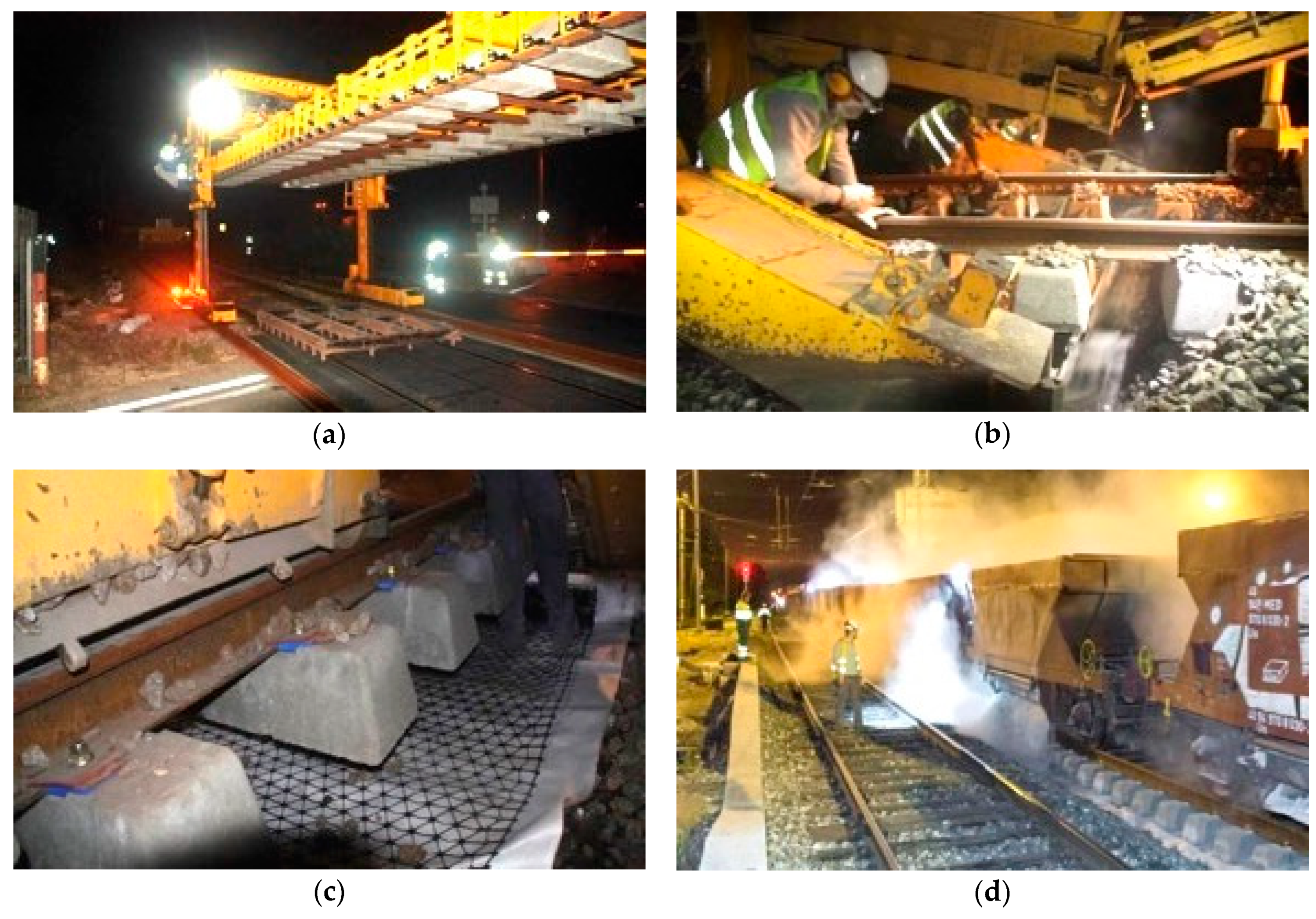
Figure 2 shows the main in situ construction phases of the rail track rehabilitation, which were carried out at night:
- (a)
Replacement of rails, sleepers, and fastenings (
Figure 2a).
- (b)
- (c)
Application of a combination of a composite of triaxial geogrid and non-woven geotextile in the base of the ballast layer (
Figure 2c).
- (d)
After the removal of the contaminated ballast, a track-mounted undercutting machine rolled out the geotextile and geogrid prior to the new ballast being dropped into place over these materials (
Figure 2c).
Vilela [
36] describes the case study with more details.
2.2. BIM Application
Application of the BIM methodology was demonstrated on a section of the case study track measuring 1787 meters in length. A straight part of the rail track was selected that was considered representative of the case study. Two-Dimensional (2D) representations of the elements of the project are available in paper format or as pdf files [
37].
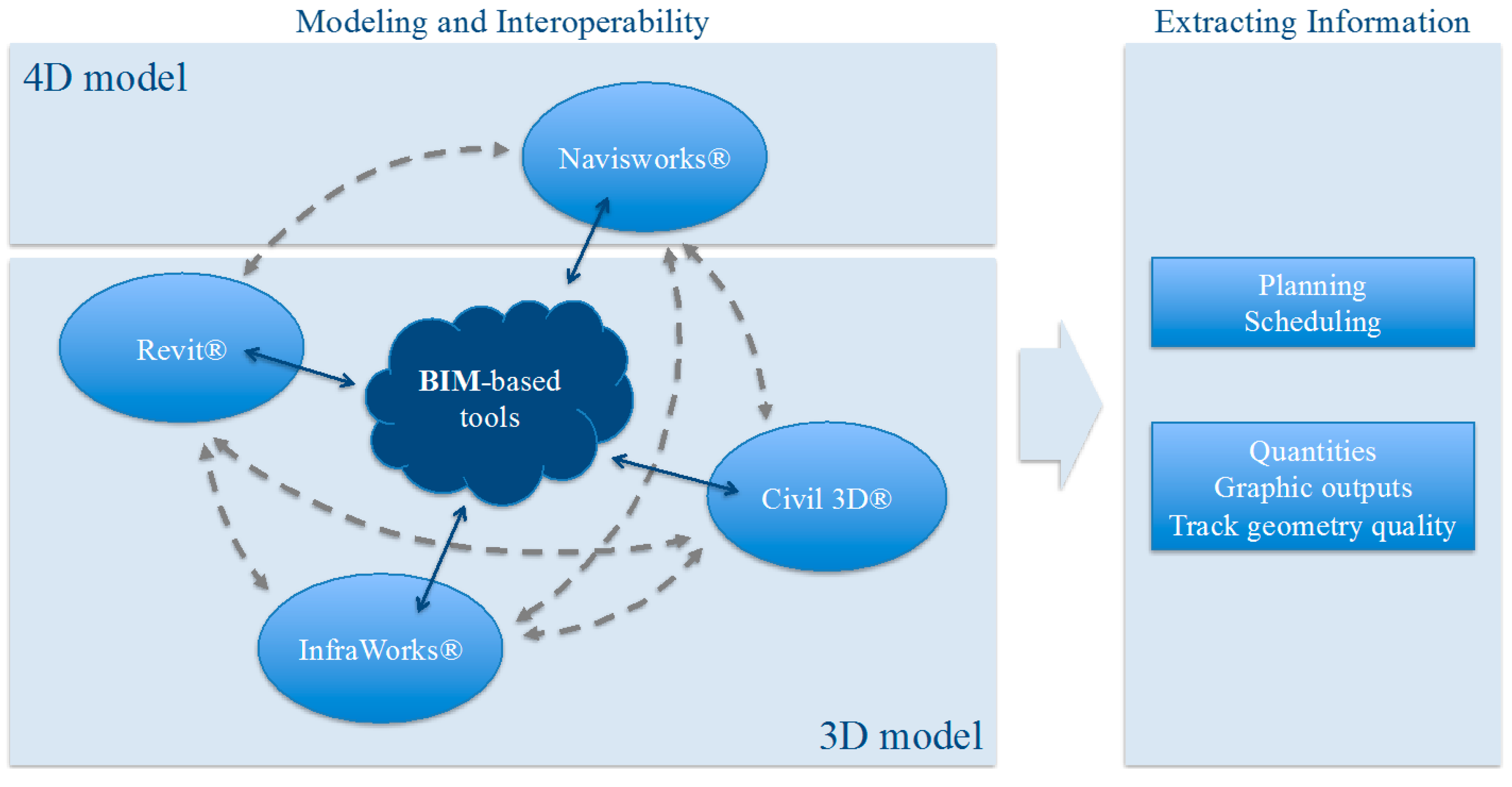
Figure 3 presents a schematic overview of the BIM implementation adopted in this paper: modeling, interoperability, and information extraction. The following Autodesk programs were used: Civil 3D®, Revit®, and Navisworks®. First of all, the geolocation of the case study area and the corresponding natural terrain modeling were carried out using InfraWorks® software. The application of BIM methodology to the case study comprised three phases: (1) creation of the project model (3D model); (2) planning and scheduling of the construction process (4D model); and (3) extraction of diverse model information.
Civil 3D® software is a common tool used in 3D modeling of transport infrastructures. Revit® software is a well-known BIM-based tool intensively used in the domain of architecture, engineering, and construction. It was also used in the 3D modeling of the railway infrastructure, with a new rail track family being created, including the rails, sleepers, and fastenings. In order to create the four-Dimensional (4D) modeling, incorporating the time element, the geometric model created in Civil 3D® was exported to Navisworks®. Using the latter software, the construction process phases for the rail track rehabilitation were recreated. Finally, the extraction of information was demonstrated: planning and scheduling, quantities of materials, graphic outputs, and track geometry quality.
3. Modeling
3.1. 3D Modeling
Civil 3D® is a program that is commonly used in the geometric design of transport infrastructures. This software was used in the case study to begin the 3D representation of the general railway infrastructure geometry based on the AutoCAD 2D elements of the project: horizontal and vertical alignments and cross-sections.
Prior to this, InfraWorks® provided the most accurate terrain modeling and geolocation of the construction site to be transferred to both Civil 3D® and Revit®. Regarding this objective, another interesting tool is the Digital Terrain Model (DTM), which consists of the three-dimensional representation of the terrain based on the digital space mapping of the area. However, it was not possible to explore this tool.
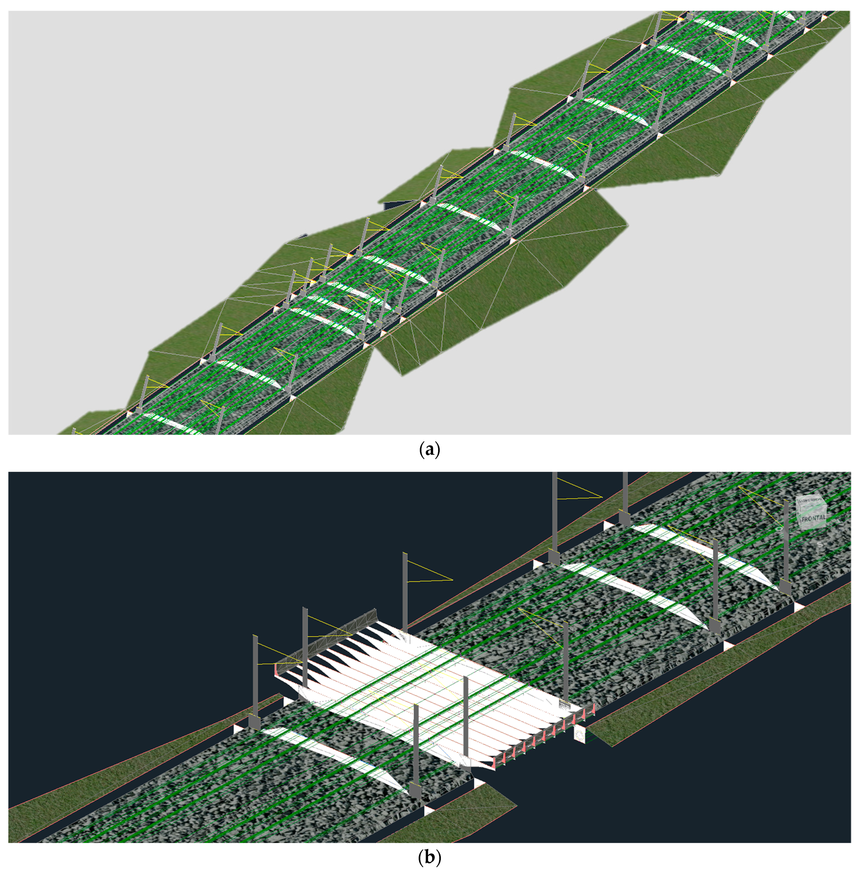
The 3D modeling of the railway infrastructure by Civil 3D® included the track substructure (subgrade and sub-ballast layers) and the superstructure (ballast layer), including also some components of the drainage (pipes) and catenary (vertical poles and cantilevers) systems. After the definition of the horizontal alignment, the longitudinal profile of the terrain was created, and finally, the vertical alignment was established in line with an adequate balance of earthworks and respecting geometric requirements. The two main cross-sections of the rail track were then designed: a section relating to the general railway line and another section corresponding to the particular case of a box culvert.
Figure 4a shows a generic part of the 3D model. In
Figure 4b is represented a box culvert integrated in the embankment.
Civil 3D® software is suitable for 3D modeling, as demonstrated once again in this railway infrastructure case study. However, it has certain limitations with regard to the application of the BIM methodology. Revit® software is a well-known BIM-based tool. The interoperability between Civil 3D® and Revit® was analyzed in the case study. However, the complete integration into Revit® of the 3D model created by Civil 3D® was not successful because most of the elements were not recognized.
Revit® has no infrastructure-oriented component, so the possibility of creating new families of objects required for the design of the rail track was explored. It was decided to use Revit® to generate families of parametric objects related to the railway components, with respect to the geometries and materials used in the case study: rails (UIC 60), bi-block concrete sleepers (VAX LU41 NG), and the corresponding types of fastenings. During this modeling, architecture, structure, and Revit® systems component commands were used.
Based on the integration of two families already existing in the BIM Library related to rail track components—rail, sleeper, and fastening—and using the
Railing command, on the
Architecture tab and in the
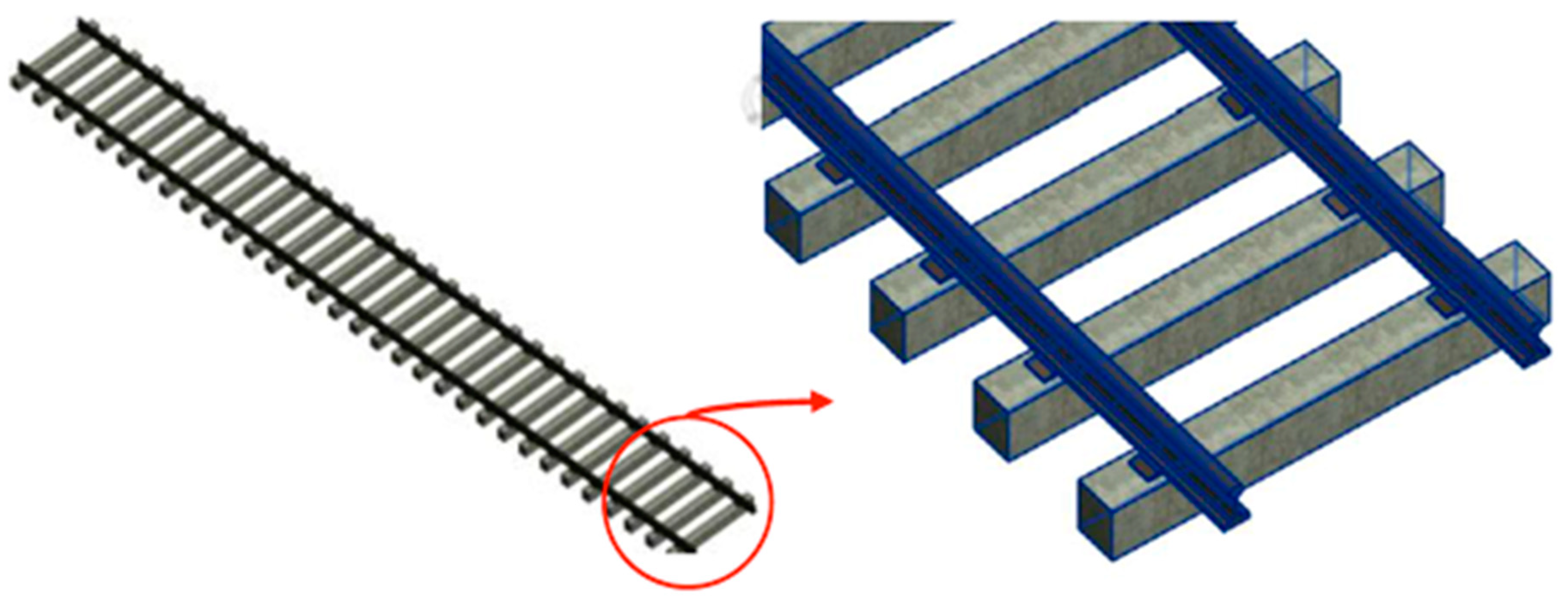
Circulation panel, a new Revit® family was created in order to represent the complete rail track: two rails, equidistant sleepers, and corresponding fastenings. In order to ensure the most accurate placement of the rails in the fastenings, some parameters were changed, e.g.,
Base offset,
Top offset, and
Distance from previous. The Iberian track gauge of 1668 mm was adopted for this family.
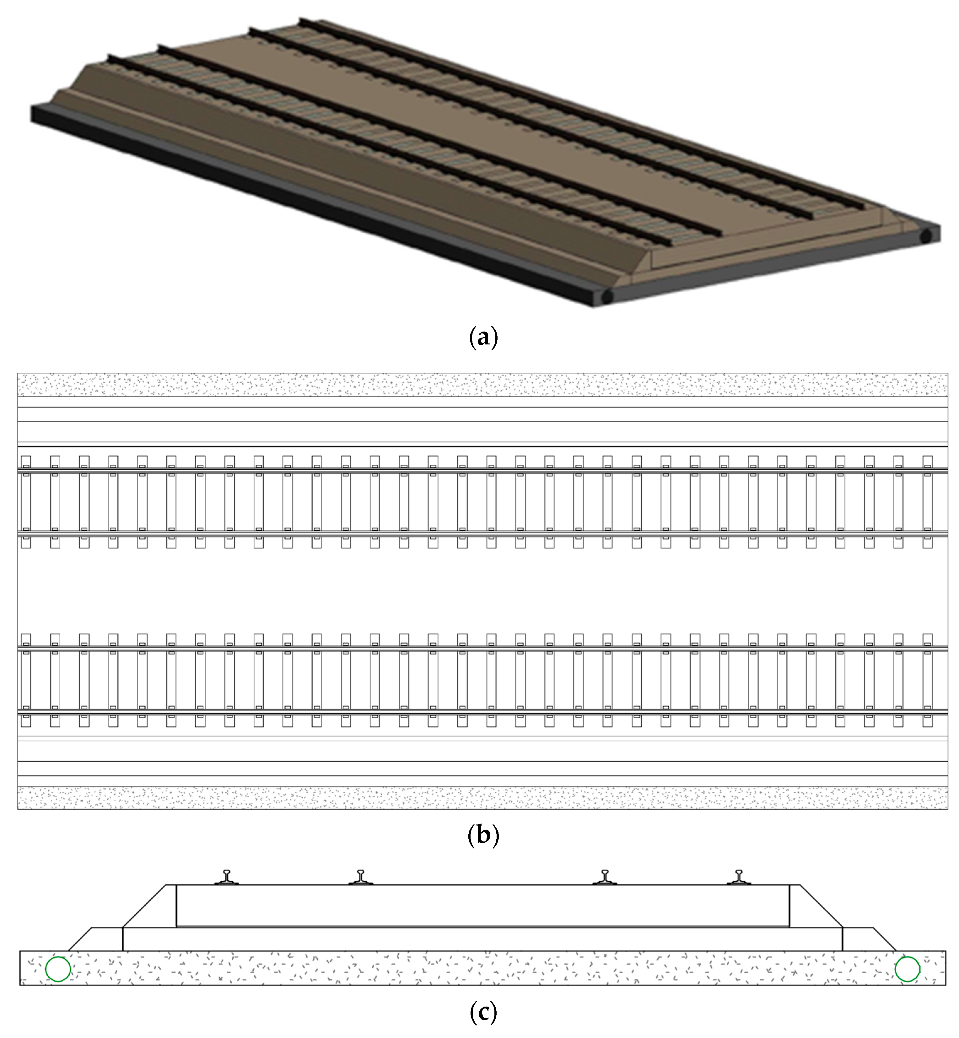
Figure 5 represents the 3D model of the rail track family created in Revit®.
The subgrade, sub-ballast, and ballast layers completed the 3D model of the basic rail track infrastructure and superstructure components. These elements were created through the Structure tab, Foundation panel, and Slab command. The corresponding properties were the layer thickness and the material: sand and gravel in the case of subgrade and sub-ballast/ballast layers, respectively. By way of example, the subgrade was modeled as a slab with dimensions of 12.0 × 25.6 × 0.45 m3. For the geotextile and geogrid components, the procedure was similar: the thickness was 5.4 mm (arbitrated value), and a new material, polypropylene, was created, with the appropriate thermal and mechanical properties, in addition to other product information (e.g., manufacturer and model).
Finally, the drainage elements were included in the 3D model, using the Systems tab, Plumbing & Piping panel, and Pipe command. Two identical pipes, 25.68 m long and 400 mm in diameter, were placed in a lateral position to the foundation layer.
Figure 6 represents the 3D model of the complete rail track including drainage: a perspective representation of the global 3D model (
Figure 6a); a plan representation of the model (
Figure 6b); and a representation of the cross-section of the total rail track structure and lateral drainage pipes (
Figure 6c).
The interoperability between Civil 3D® and Revit® was also analyzed in terms of the terrain modeling. To import the terrain model, the
Import CAD command was selected in the
Import panel of the
Insert tab. Then, the terrain surface was optimized using the
Toposurface command in the
Model Site panel,
Massing & Site tab. In a new tab, the
Create command from
Import was selected.
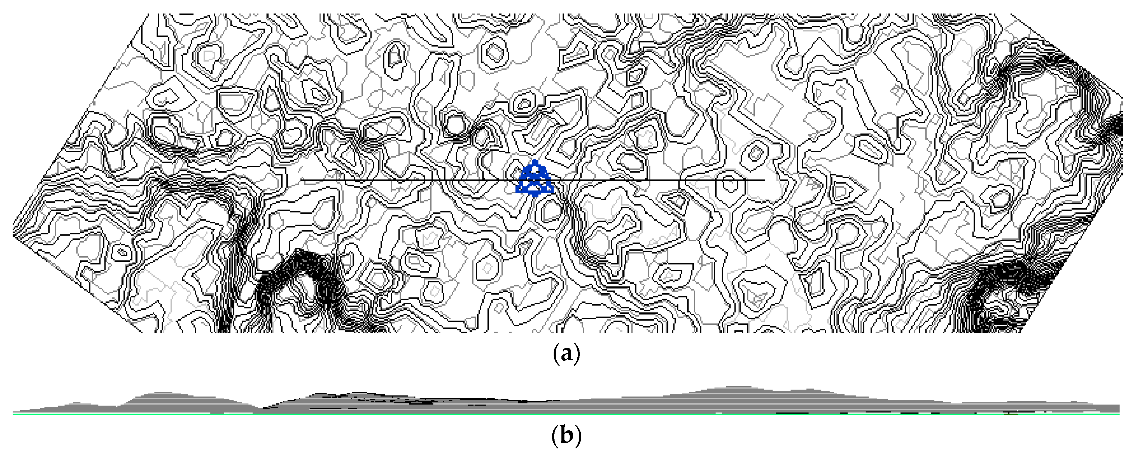
Figure 7 shows the final terrain model that was obtained: plan view (
Figure 7a) and longitudinal profile (
Figure 7b).
3.2. 4D Modeling
The 4D BIM includes the time parameter that was applied in the construction planning and scheduling of the rail track rehabilitation. Navisworks® was the software used to create the 4D model. The construction planning and scheduling can be created directly in Navisworks® by means of Microsoft Project® import, or manually. Due to the restricted case study dimension, we opted for the manual process.
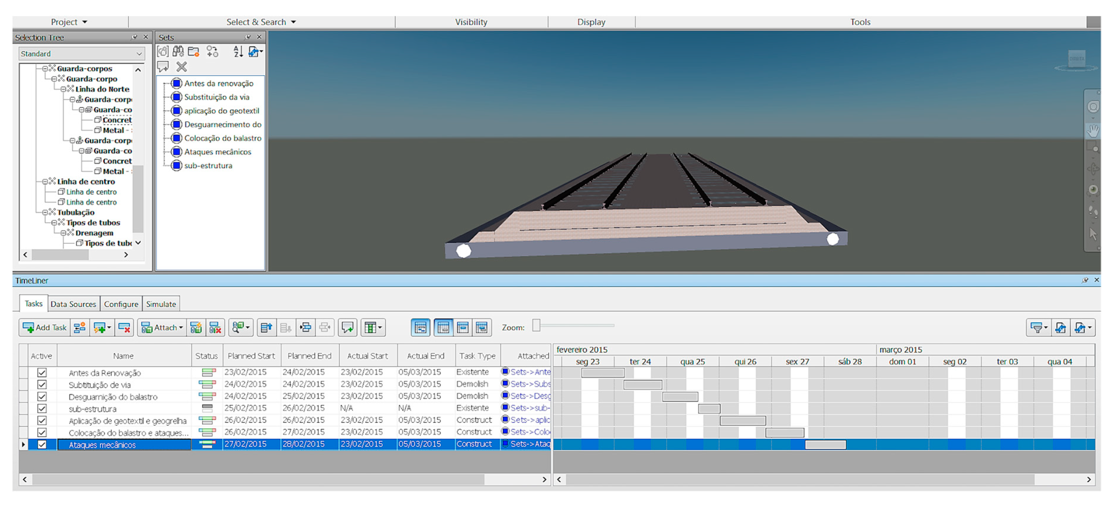
Seven sets were created to illustrate the different construction phases: existing rail track; replacement of track; removal of ballast; substructure; application of geotextile and geogrid; new ballast tamping; and final track tamping. Each set was created by selecting the components of the geometric model that correspond to that phase. Subsequently, construction tasks were added, including the planned beginning and end dates. In order to create the construction sequence, the TimeLiner command was used in the Home tab and Tools panel. The construction tasks were manually introduced into the schedule plan. Each of the various sets was allocated to its respective task.
A Gantt chart, concerning the rehabilitation of the rail track segment, was established directly within the Navisworks®. Using the capacity of this BIM viewer, each task was linked to the correspondent construction component (ballast, substructure, geotextile, and geogrid). To accomplish this operation, the BIM model was created in a way that allowed the representation of each construction step. As such, it was possible to establish adequate links between geometric construction phases, representing the physical construction progress of the rail track rehabilitation, as illustrated in
Figure 8.
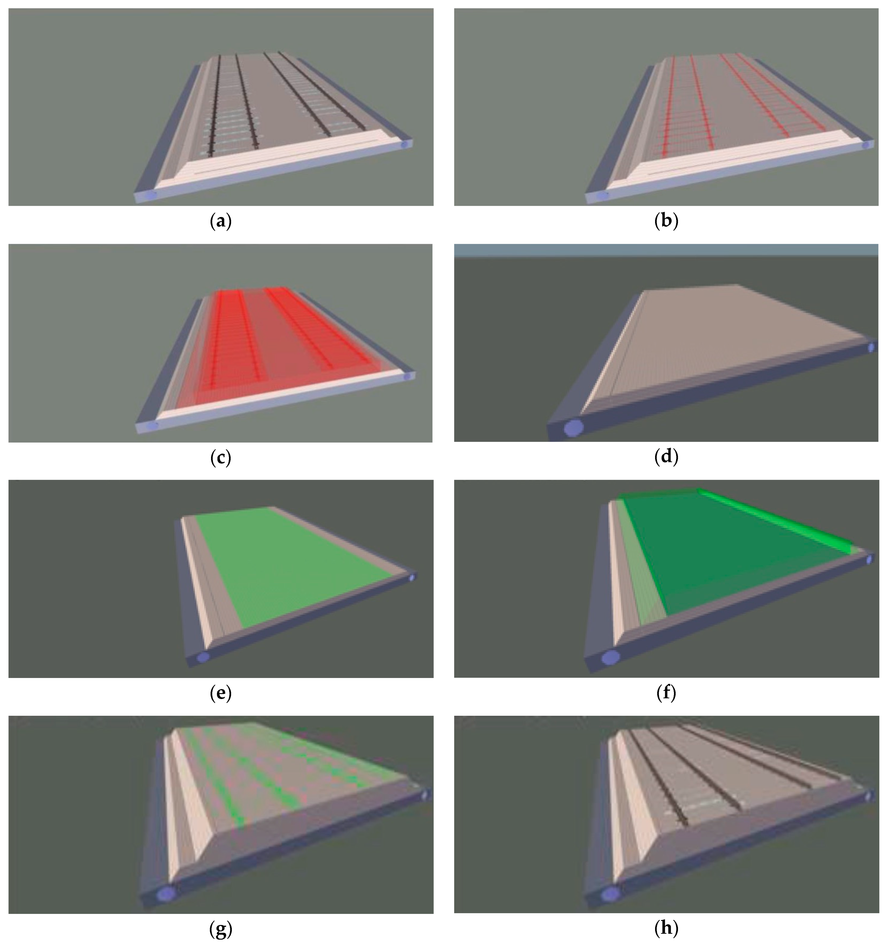
Figure 9 represents the construction phases: (a) existing rail track; (b) replacement of track; (c) removal of ballast; (d) substructure; € application of geotextile and geogrid; (f) new ballast tamping; (g) final track tamping; and (h) rehabilitated rail track. The elements represented in green were the object of construction during the task, and the elements in red correspond to a removal or demolition process as part of the task. The two tasks, “existing rail track” and “substructure”, were not real, but they were included with the aim of obtaining a more realistic simulation of the construction phases. The simulation of the different tasks planned for the rail track rehabilitation was obtained through the
Simulate tab of the
TimeLiner command.
4. Discussion
Interoperability between systems plays a very important role in the BIM methodology. In
Figure 3, the links between BIM software packages represent the interoperability analyzed in the case study. As already stated, difficulties were identified in terms of interoperability between some systems. In some cases, interoperability was even impossible. Taking into consideration that the programs used in the case study analyses were all from Autodesk, interoperability seemed to be guaranteed; but this could not be confirmed.
The creation of 3D models was always possible, although with certain limitations, because initially, the modeling would be carried out only in Civil 3D®. We later confirmed that this program was not the most suitable for the BIM methodology. Whilst Civil 3D® allowed for the creation of 3D representations quite correctly, the generated models were still based on lines and surfaces, as with the traditional AutoCAD 2D® software. This situation introduced interoperability issues, which have restricted the process for the definition of 4D models. The interoperability between the Revit® and Navisworks® software packages facilitated the process of creating the tasks associated with the case study, with respect to the 4D modeling.
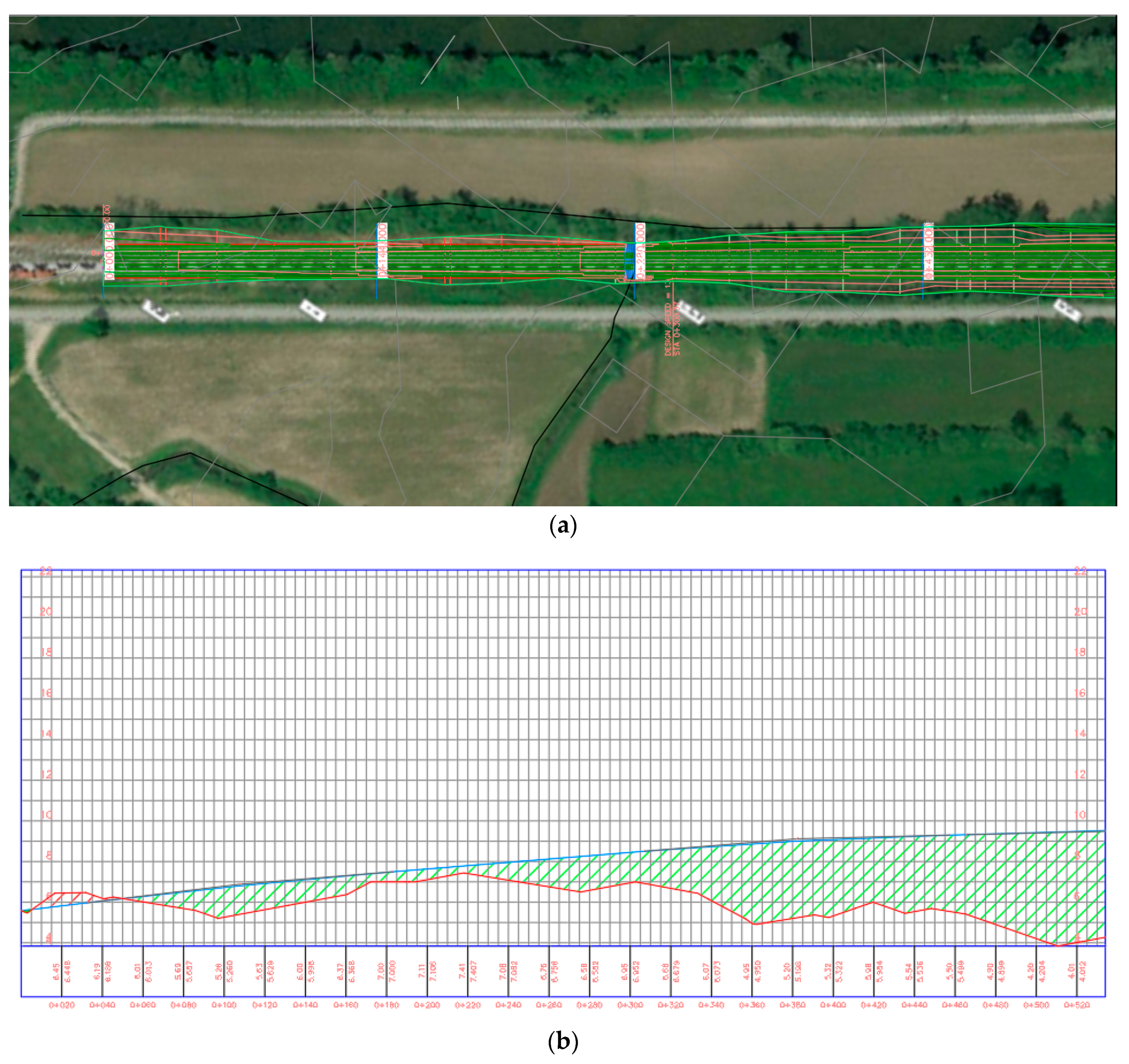
In BIM, it is possible to use tools that allow for extraction of a range of information from the models created. One of the most important components of a project is the drawing outputs, and it is a fundamental requirement that the designer can easily update them when changes and adjustments are made to the project.
Figure 10 presents the graphic representation of the horizontal view (
Figure 10a) and longitudinal profile (
Figure 10b) of the rail track obtained from Civil 3D®. To obtain a drawing, a rectangle was first created, using the
Create View Frames command in the
Drawing Production panel, which was included in the
Output tab. Then, to create the graphic outputs for alignment and the longitudinal profile, the
Create sheets command was selected in the
Drawing Production panel and
Output tab.
However, drawings extracted from the 3D models were generally very incomplete, with respect to dimensions, annotations, and other informative text. Additional information, identical to the common information required in AutoCAD 2D® software, was required.
The quantities of materials were a further type of information extracted from 3D models (Civil 3D® and Revit®). This information was based on the measurement of the volumes of ballast and sub-ballast, the surface areas of geotextile and geogrid, and also the volumes for earthworks (landfills and excavations). It was likewise possible to extract information on rails, sleepers, and drainage elements. The sole limitation was the impossibility of quantifying the sleepers and rails because they were generated as a global parameter in Revit®, and not individually.
To ensure adequate and safe rail track behavior, monitoring of the quality of the construction and throughout the lifecycle of the railway infrastructure is crucial. Inspections are carried out to monitor the track condition. According to the EN 13848-1 standard, the main track geometric quality parameters are longitudinal leveling, transversal leveling, alignment, gauge, and twist. In Civil 3D®, it was only possible to control two geometric parameters: the gauge and transversal leveling. Further development is needed so that this very important functionality can be fully implemented in the BIM methodology.
Finally, the 4D model created in Navisworks® was very useful for producing flow and Gantt charts related to the planning and scheduling of activities.
The present work is focused, mainly, on the rehabilitation of a segment of railroad and not on obtaining information concerning the inspection or irregularities found in specific points along the track. However, as a complement to the present study, the inspection and control of the geometry is a perspective of great interest, to be developed in future work.
5. Conclusions
Major efforts are currently being made towards achieving a more generalized implementation of the BIM methodology in the domain of transport infrastructures, beyond specific components, e.g., tunnels, viaducts, and bridges. The aim of this paper was to contribute to this main goal through the demonstration of an application to a rail track rehabilitation case study.
The application of the BIM methodology consisted of three phases: (1) creation of the project model (3D); (2) planning and scheduling of the construction process (4D); and (3) extraction of diverse model information. The objectives of these phases were achieved in general using different software packages. The Civil 3D® and Revit® packages proved suitable for 3D modeling, including the rail track, drainage, and catenary systems. Interoperability between these tools was analyzed. However, the total integration into Revit® of the 3D model created by Civil 3D® was unsuccessful because most of the elements were not recognized. Based on the integration of two rail track component families existing in the BIM Library, a new Revit® family was created in order to represent the complete rail track. The Navisworks® program was used to create the 4D model. Seven sets were created to illustrate the different construction phases: existing rail track; replacement of track; removal of ballast; substructure; application of geotextile and geogrid; new ballast tamping; and final track tamping. It was also possible to establishing adequate links between geometric constructions, representing the physical construction progress. The interoperability between the Revit® and Navisworks® packages facilitated the process of creating the tasks associated with the case study, regarding the 4D modeling.
BIM tools allowed for extraction of diverse information from the created models: planning and scheduling; quantities of materials; graphic outputs; and track geometry quality. This information is useful for the design, construction, and exploration of transport infrastructure.
In the domain of transport infrastructure systems, the railways present specificities and complexity that confer to BIM implementation a greater interest and importance. The highest safety exigencies of the railway operation (e.g., high speed train) require more frequent monitoring and maintenance operations. Additionally, the complexity of railway components and systems (infrastructure and vehicles) requires better tools for data analysis and processing. In this sense, BIM will be a useful methodology with enormous technical, economic, and environmental advantages along the railway infrastructure lifecycle. The application of BIM-based tools to the case study described in this paper has demonstrated that, in spite of certain difficulties and limitations, the methodology has great potential and should be explored further.
For the future development of BIM implementation in the domain of transport infrastructures, advancement of the development of families specific to transport infrastructures is recommended, particularly in Revit®, so that projects can be modeled more easily and also be more complete and realistic. Another important recommendation is the integration in the BIM methodology of an adequate track inspection system that includes all the usual geometric parameters, so that maintenance planning associated with quality control inspection tests can be integrated. It is also believed that the reported issues on the interoperability between BIM tools will be overcome in the short term, taking into account the current and foreseeable evolution of the digital systems.

