1. Introduction
Bridge failures occurring during construction differ fundamentally from failures of completed bridges because structural configuration, restraints, boundary conditions, load paths, and redundancy change between erection stages. Construction-stage reliability therefore cannot be inferred solely from the adequacy of the completed bridge and should be evaluated for each safety-critical erection configuration [
1,
2,
3]. The importance of such stage-specific assessment has also been demonstrated by Zucca et al. [
4], who showed through staged numerical analysis that an unplanned re-tensioning operation increased demand at a critical structural node and contributed to the construction-stage collapse mechanism of a post-tensioned reinforced-concrete truss bridge.
This distinction is particularly important for long-span arch and cable-supported bridges. Before arch closure, the permanent load path and global stability system are incomplete, and partially erected ribs and deck segments may depend on temporary towers, tie cables, backstays, anchorage beams, distribution beams, and bracing. During this phase, these nominally temporary components may function as primary load-bearing elements, and their loss can remove a critical force-transfer path supporting substantial portions of the incomplete structure.
Safety requirements for temporary works have consequently evolved toward consequence-based reliability specification [
1,
5]. Because construction stages generally involve shorter exposure periods than the permanent design situation, the appropriate reliability target need not be identical to that of the completed structure and may be calibrated to both exposure duration and failure consequence [
1]. Although permanent structure reliability increasingly incorporates structural system redundancy [
6], temporary works reliability remains less unified [
7,
8,
9], and bridge-failure surveys continue to identify temporary works and erection-stage components as important contributors to construction-stage failures [
8,
10,
11,
12]. Recent research has therefore emphasized stage-specific analysis of cable-supported bridges [
13,
14], including steel arch and tied-arch systems erected by cantilevering with temporary stays [
15,
16,
17].
Nevertheless, temporary works may still be treated institutionally as construction means and methods rather than as safety-critical structural systems. Comparative guidance therefore emphasizes defined responsibilities, documented design control procedures, checking proportionate to structural complexity and failure consequence, and controlled authorization throughout the temporary works lifecycle [
18]. Gaps between global structural analysis and local-detail verification can leave consequential connections insufficiently assessed. The I-35W deck truss collapse illustrates this broader principle: calculations undertaken for construction loading considered the principal truss members but not the inadequately designed gusset plates that ultimately initiated failure [
19]. Although the I-35W accident involved an in-service bridge subjected to concentrated construction loads rather than an incomplete erection system, it demonstrates a broader principle directly relevant to construction-stage safety: the resistance of the global structural system cannot exceed that of its most consequential load-transfer detail.
Connection quality is therefore central to bridge safety. Bolted connection behavior depends on fastener properties, bolt and hole geometry, alignment, thread position relative to the shear plane, plate contact, installation conditions, and fastener engagement. Oversized or irregular holes, missing fasteners, and field modifications may produce differential slip, nonuniform load sharing, and progressive redistribution within the bolt group [
20,
21,
22]. Where alternative load paths are limited, loss of a single member or connection can produce disproportionate system-level consequences, emphasizing the need for robustness assessment under explicit local-damage or component-removal scenarios [
5,
6,
23,
24,
25].
Construction monitoring provides an additional, but not independent, detective barrier. Global quantities such as cable force, cantilever geometry, and tower inclination can identify departures from expected construction-stage response but cannot verify local material conformity, hole geometry, or fastener engagement. Local connection measurements may improve detection of abnormal response, although abrupt internal failure may provide little actionable warning. Monitoring should therefore supplement preventive quality controls, while structural robustness and personnel exclusion remain necessary where intervention time is limited [
25,
26,
27].
Document-based failure investigation requires traceable separation between observations, source-reported findings, calculations, engineering interpretations, and unresolved uncertainty [
28]. Fault-tree, bow-tie, barrier, and organizational accident frameworks additionally provide structured means of relating physical failure to preventive, detective, consequence-limiting, and organizational controls [
29,
30,
31,
32].
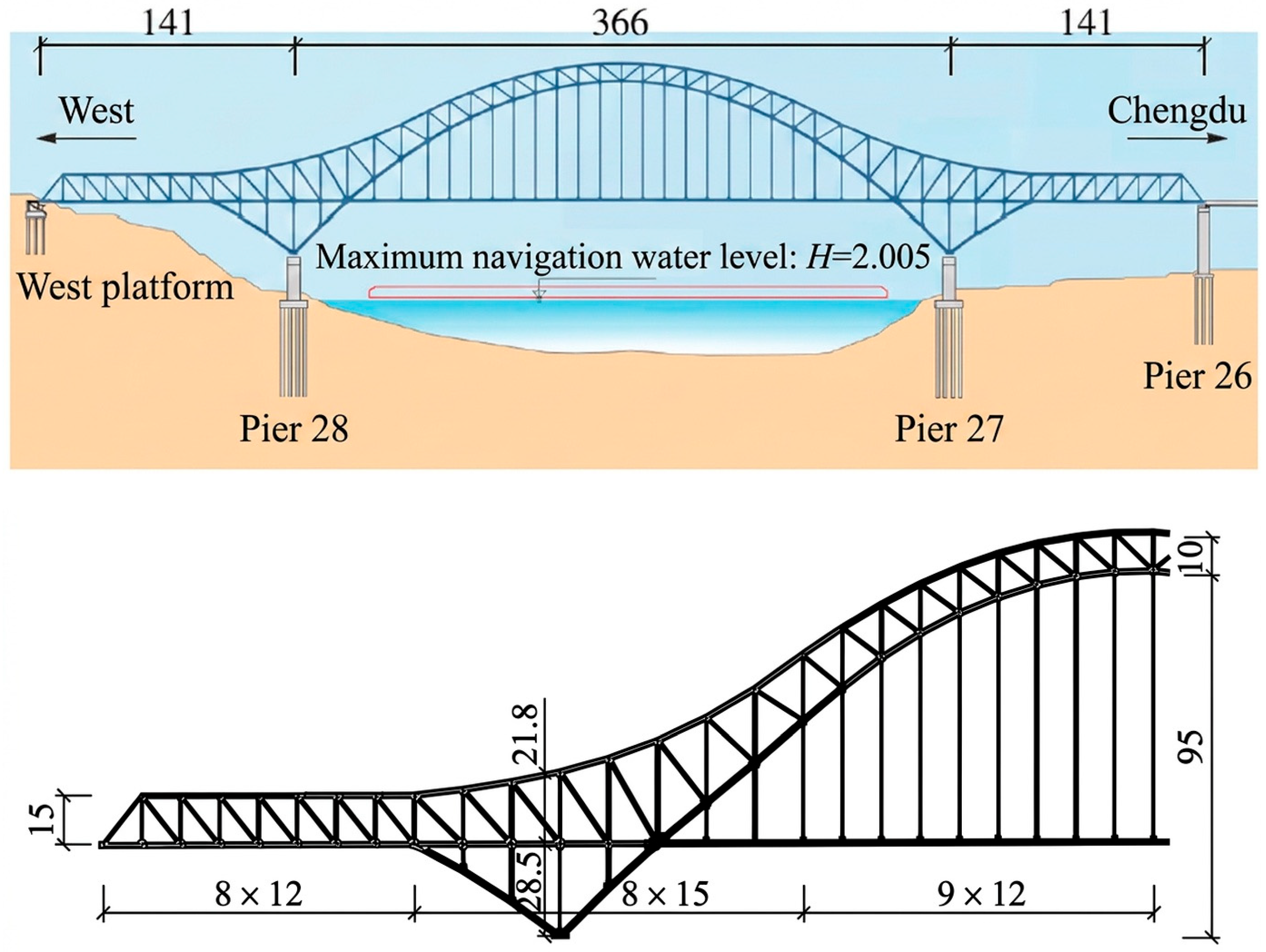
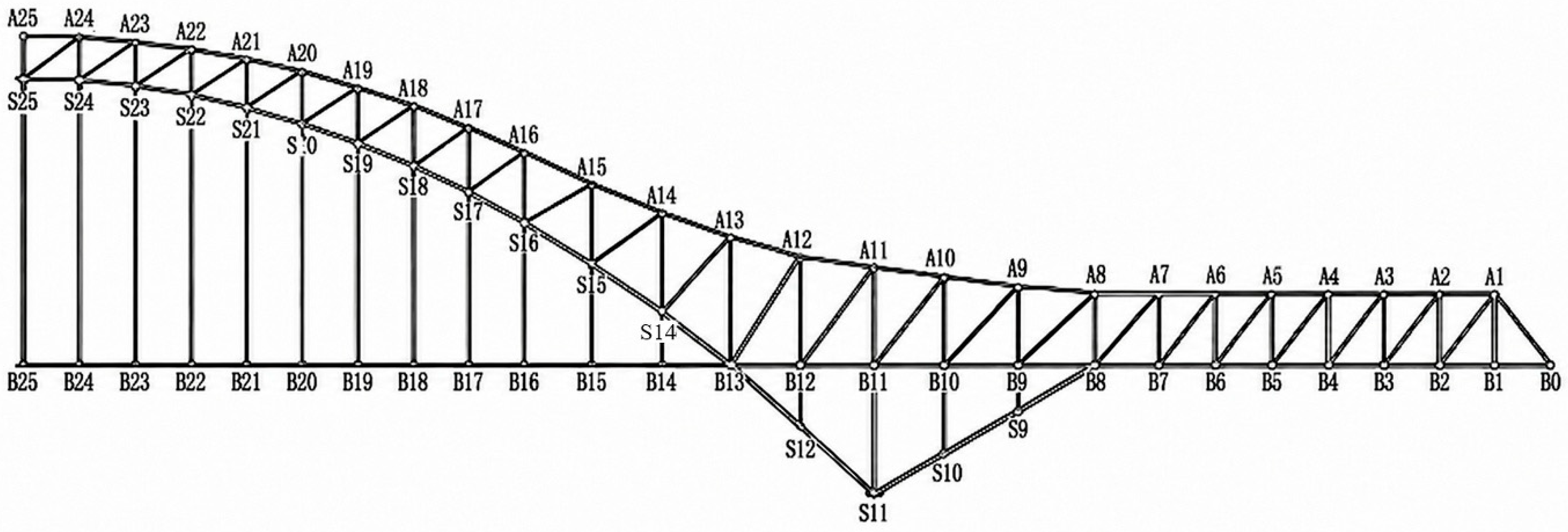
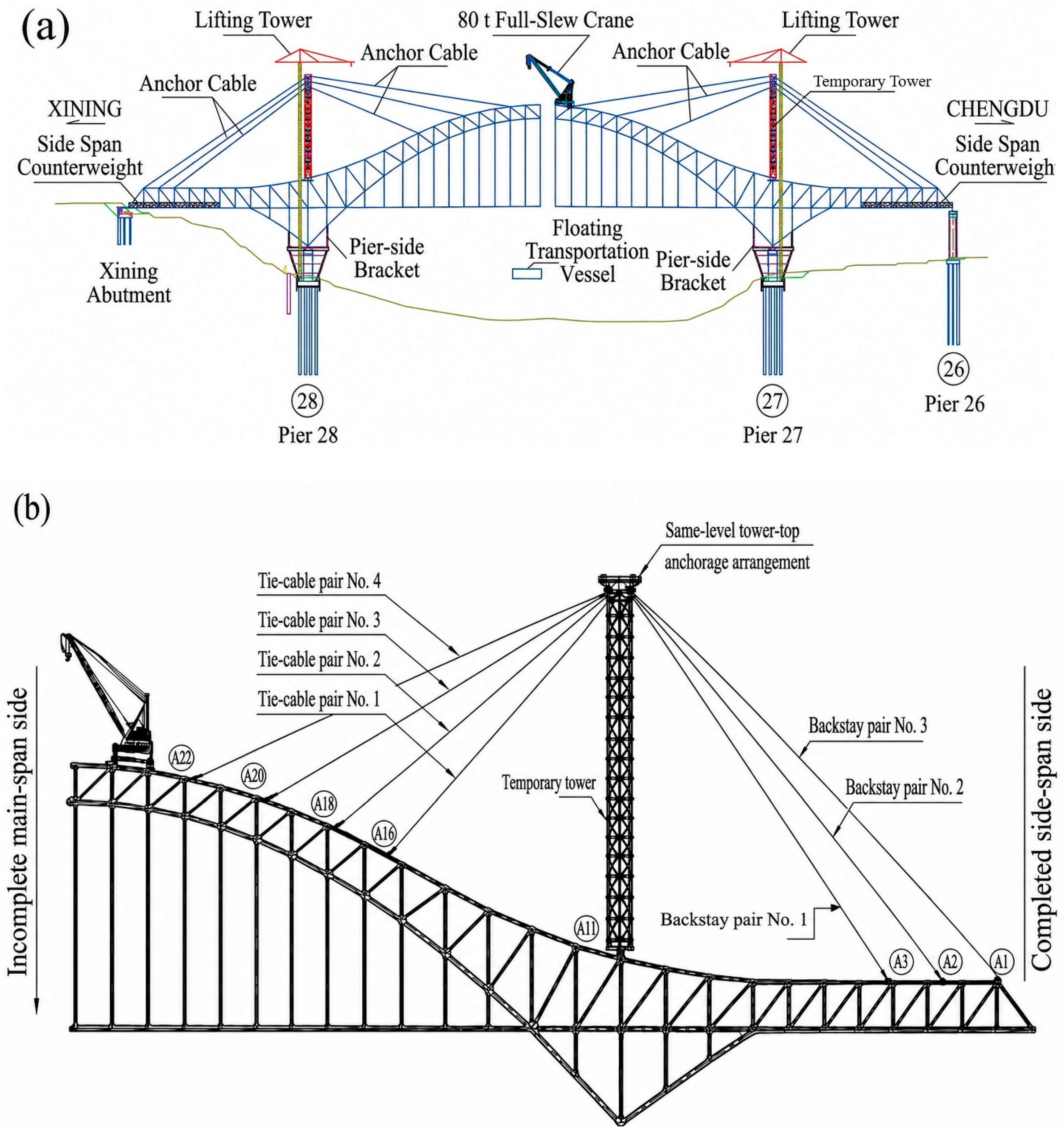
Against this background, the collapse of the Jianzha Yellow River Super Bridge provides an important contemporary case for bridge engineering. The bridge forms part of the Xining–Chengdu Railway in Qinghai Province, China. Its principal crossing was designed as a three-span, double-track continuous steel truss arch with spans of 141 + 366 + 141 m, erected using cantilever construction assisted by a temporary cable-supported system [
33,
34]. At approximately 03:01 on 22 August 2025, part of the nearly completed main bridge collapsed during the pre-closure construction stage, resulting in 13 fatalities, 3 missing persons, and direct economic losses of approximately CNY 48.86 million [
35]. Early reporting attributed the accident to the visible rupture of a construction cable. The official investigation, released on 8 April 2026, concluded that bolt-group shear failure and separation at a tower-top distribution beam splice was the initiating physical event following second-stage tensioning of the No. 4 tie cable. In the load-path interpretation developed here, loss of continuity at that splice would have interrupted a primary temporary support path before arch closure; the exact time and progressive development of the splice failure remain unknown [
35].
The official investigation did not attribute the accident to an extraordinary environmental action or to a general lack of capacity in the permanent bridge concept. Instead, it identified an initiating failure in a comparatively localized component of the temporary erection system, followed by system-level collapse [
35]. The official investigation further identified deficiencies extending beyond the physical connection, including the procurement of nonconforming bolts, uncontrolled subcontracted fabrication, deficient installation, ineffective inspection and acceptance, inadequate monitoring and supervision, and failures of safety responsibility across the participating organizations [
35]. On the basis of the official findings, the case may be interpreted as involving three interacting layers: the defective physical connection, reported failures of technical controls that should have prevented or detected the deficiencies, and reported organizational weaknesses that allowed the temporary component to be fabricated and accepted without adequate verification.
Pre-accident publications describe the intended structural system, erection concept, and principal bridge characteristics [
33,
34], whereas the official investigation report provides the controlling accident-specific findings, including the chronology, initiating splice failure, material and dimensional deficiencies, construction-stage loading conclusions, and organizational findings [
35]. These findings are not redetermined in the present study but constitute the evidentiary basis for the subsequent engineering analysis.
No peer-reviewed English-language study was identified that integrates this accident evidence within a construction-stage load-path, connection mechanics, robustness, and safety barrier framework while explicitly separating official findings from author-derived analysis and interpretation. The individual analytical tools used here—including load-path tracing, conventional bolted connection mechanics, component removal reasoning, and qualitative barrier analysis—are established methods and are not claimed as novel. The contribution instead lies in their evidence-graded integration to clarify the structural significance of the failed splice, provide bounded quantitative and mechanical consistency checks, distinguish observed chronology from unresolved propagation processes, and identify transferable intervention pathways.
Accordingly, the study distinguishes three levels of output: (1) accident-specific findings reported by the official investigation; (2) author-derived evidence mapping, load-path and topology reconstruction, quantitative consistency checks, connection mechanics interpretation, temporal analysis, robustness assessment, and qualitative barrier analysis; and (3) transferable temporary works lessons concerning consequence-based classification, local-detail verification, field-change control, monitoring, robustness, and personnel exclusion. The study does not independently redetermine the accident cause or reconstruct the complete as-built splice capacity or nonlinear collapse response; the source access limitations are defined in
Section 2.
2. Evidence, Methodology, and Limitations
2.1. Research Design and Evidence Status
This study adopted a document-based forensic engineering case study methodology. The official investigation report [
35] was treated as the controlling source for accident-specific chronology, physical findings, test results, construction-stage loading conclusions, and organizational findings, while independently accessed design publications, standards, and engineering literature were used for structural context, mechanical interpretation, and transferable recommendations. The author was not affiliated with the investigation team and did not independently access the accident site, recovered components, original footage, raw test or monitoring data, original structural models, or underlying third-party calculations. Independent work was therefore limited to evidence classification, transparent calculations using reported values, load-path and robustness interpretation, barrier analysis, and literature synthesis. These general source access limitations apply throughout the study and are repeated subsequently only where they materially affect a specific interpretation.
To distinguish the contribution of the present study from that of the official investigation, all substantive information was classified into four categories:
Official findings: Conclusions explicitly reached by the official investigation team, including the reported initiating component, material test results, dimensional nonconformities, construction-stage loading conclusions, accident chronology, and organizational deficiencies.
Evidence reproduced through the official investigation report: Measurements, photographs, video-frame descriptions, material test findings, site observations, and third-party calculation results that were described or reproduced in the report but whose original records were not independently accessed by the author.
Author-derived analysis: Transparent calculations or analytical arrangements produced in this study using reported values, including elapsed-time calculations, normalized individual-bolt resistance calculations, evidence-status mapping, construction-stage load-path schematization, and safety barrier classification.
Engineering interpretation and literature synthesis: Mechanically supported inferences and recommendations developed by relating the reported evidence to established concepts in bolt-group mechanics, staged construction, structural robustness, monitoring, temporary works reliability, and organizational accident analysis.
These evidence labels are used consistently throughout the manuscript. Author-derived interpretations are not presented as independently verified forensic facts, and unresolved matters are identified explicitly as uncertainties.
Table 1 operationalizes this distinction, while transferable outputs are developed further in
Section 6.5,
Section 7,
Section 7.1,
Section 7.2,
Section 7.3,
Section 7.4 and
Section 8.
For orientation, the official investigation identified bolt-group shear failure and separation at a tower-top distribution beam splice following second-stage tensioning of the No. 4 tie cable as the initiating physical event. The failure occurred while the arch remained unclosed and dependent on the temporary cable-supported erection system; visible cantilever descent was subsequently followed by cable rupture, arch-rib fracture, and extensive structural collapse [
35].
2.2. Evidence Hierarchy and Source Selection
Table 1 classifies the evidentiary and analytical role of individual claims, whereas
Table 2 summarizes source provenance and access. No independently accessed primary accident evidence was available.
The principal accident-specific source was the 62-page official investigation report issued by the Qinghai Provincial Government Accident Investigation Team [
35]. It was treated as the controlling source for chronology, causal conclusions, physical findings, construction-stage loading conclusions, and organizational findings. Material test results, dimensional measurements, photographs, video descriptions, project records, and third-party calculations reproduced in that report were not independently accessed and are therefore treated as report-reproduced evidence rather than independent sources. Two pre-collapse design publications [
33,
34] were used only to establish the intended bridge configuration, erection concept, and terminology; where they differed from the accident-stage configuration documented by the investigation, the official report took precedence.
Standards and broader technical literature were used only to assess mechanical plausibility and support interpretation, comparison, and recommendations. These sources covered bolted connection behavior and applicable steel provisions [
20,
22,
36,
37,
38], temporary works reliability and governance [
1,
7,
8,
9,
18], staged analysis of cable-supported and cantilever-erected bridges [
2,
3,
13,
14,
15,
16], structural robustness and monitoring [
5,
6,
23,
24,
25,
26], forensic and barrier analysis methodology [
28,
29,
30,
31,
32], and selected historical bridge failures [
19,
27,
39,
40,
41,
42,
43,
44,
45]. They were not used to independently verify Jianzha-specific facts.
2.3. Data Extraction and Evidence Coding
A structured evidence matrix was used only to maintain traceability between the documentary sources and subsequent analysis. Extracted information covered the bridge and erection configuration, critical construction operation, physical and material findings, event chronology, and safety controls. Each item was coded as an official finding, report-reproduced evidence, author-derived analysis, or engineering interpretation according to
Section 2.1. These categories are coding domains rather than independent evidence streams or analytical methods. Where a statement contained both reported evidence and author interpretation, the two elements were separated. Chinese technical terminology was translated according to engineering meaning.
2.4. Analytical Questions and Outputs
Each procedure addresses a distinct engineering question and produces a defined author-derived output from the official-report evidence; none creates independent accident evidence.
2.4.1. Construction-Stage Load Path, Topology, and Component Removal Reasoning
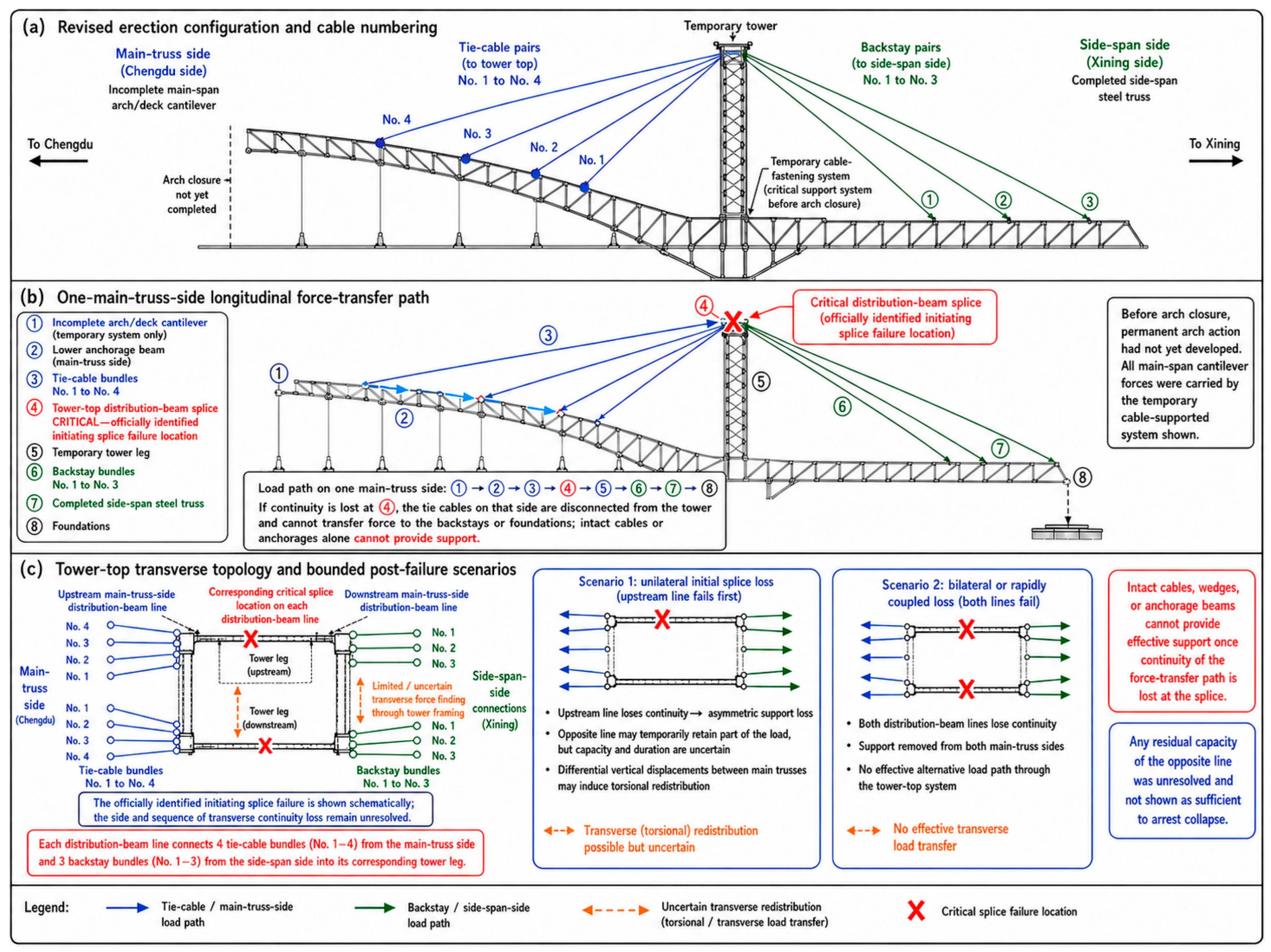
This procedure addressed the structural role of the officially identified splice before arch closure and the bounded system consequences compatible with its loss. The load path was traced through the temporary cable-supported system, and unilateral, bilateral, or rapidly coupled splice loss scenarios were considered. The resulting output is a bounded topology interpretation showing that splice loss interrupted at least one primary temporary support line and that the observed propagation is compatible with insufficient residual support or arrest capacity. No quantitative analysis was performed regarding load redistribution, torsional effects, residual capacity, or dynamic collapse.
2.4.2. Event Sequence Reconstruction
This procedure distinguished events directly established by the documentary chronology from unresolved internal processes. Reported timestamps and video-frame descriptions were assessed using temporal precedence and load-path compatibility. The resulting output separates the observed sequence—cantilever descent, cable rupture, arch-rib fracture, and extensive collapse—from the unobserved processes preceding visible movement. The post-tensioning interval is therefore treated only as a temporal bound. Detailed results are presented in
Section 4.1.
2.4.3. Normalized Individual-Bolt Resistance Assessment
This procedure assessed the combined individual-fastener effect of the two quantitative bolt deficiencies reported by the official investigation: reduced material strength and reduced resisting area at the threaded shear plane. The resulting normalized individual-bolt resistance indicator and sensitivity range are used only as a consistency check and do not estimate bolt-group resistance, complete splice capacity, or the accident-specific capacity–demand ratio. Details are presented in
Section 4.3.
2.4.4. Fault-Tree, Bow-Tie, and Barrier Analysis
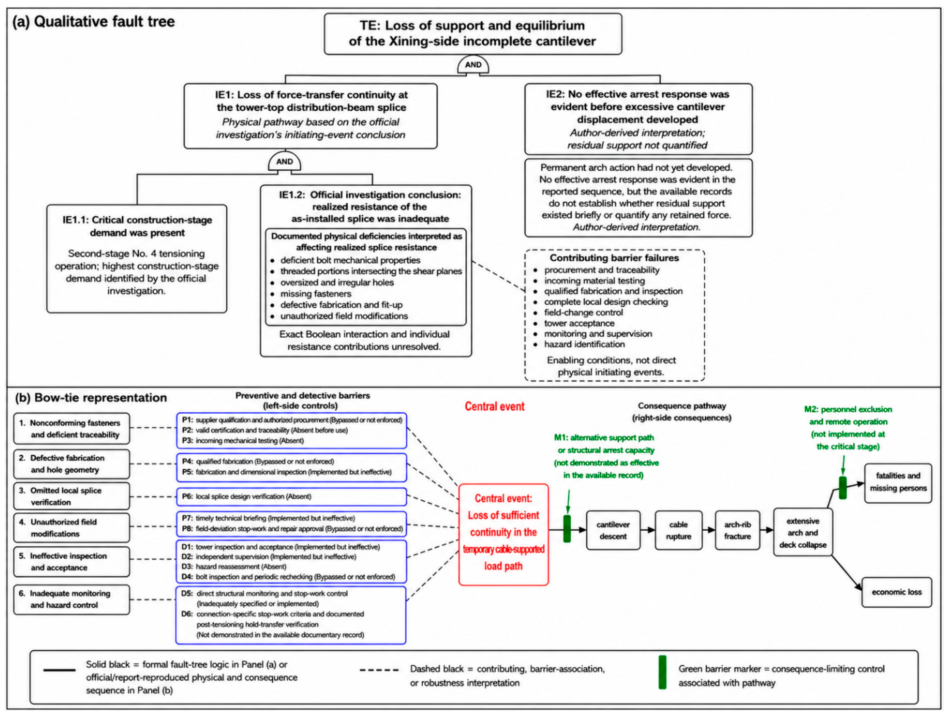
This procedure identified where independent controls could have prevented, detected, interrupted, or limited the documented failure pathway. The fault-tree and bow-tie representations organize preventive and detective controls before loss of continuity, while consequence-limiting controls are mapped after loss of continuity, with barrier status classified from the documentary record. The output is an evidence-constrained ordering of three intervention pathways: material and fabrication conformity, engineering verification and field-change control, and detection/consequence limitation. No probabilities, minimal cut-sets, or quantitative barrier-effectiveness rankings were calculated.
2.5. Selection of Illustrative Historical Bridge Failures
The historical cases were selected purposefully for mechanism-based comparison rather than through a systematic review protocol. Candidate cases were identified from official inquiry reports, governmental archives, established bridge-failure literature, and reference tracing from those sources. A case was retained when it satisfied at least two of the following criteria: (1) collapse occurred during construction or under a construction-related load state; (2) the incomplete or temporarily supported structure depended on a safety-critical erection component; (3) failure initiated in a localized member, connection, diaphragm, support, or temporary works element; (4) fabrication incompatibility, field intervention, design-checking deficiency, or inadequate inspection contributed to the failure; and (5) local failure propagated into disproportionate structural loss. The cases were selected on the basis of mechanism-level relevance to Jianzha rather than direct structural similarity. The resulting set spans different structural forms, historical periods, and failure-control deficiencies, allowing recurrence of higher-level load-path and control mechanisms to be examined across different bridge systems. These differences are not interpreted as evidence of causal equivalence. Because the selection was purposive rather than systematic, the six cases are not claimed to be the only failures satisfying the stated criteria. They were retained as sufficiently documented principal comparators for mechanism-based comparison with the Jianzha collapse; while other relevant failures are used contextually where their relevance is narrower. The comparison is illustrative and not statistically representative, and it is not intended to validate the Jianzha collapse mechanism through historical analogy.
Accordingly, the comparison can support mechanism-level contextualization and the transferability of selected engineering lessons, but it cannot establish structural equivalence, identical causal pathways, quantitative similarity, or independent validation of the Jianzha collapse mechanism. The comparison evaluates five attributes, consolidated into three analytical categories: construction or loading state; initiating deficiency, triggering demand or operation, and collapse propagation; and bounded relevance to Jianzha. Official inquiry or investigation reports were treated as the controlling sources for accident-specific findings, while peer-reviewed or established technical syntheses were used only to supplement the engineering context. For the Second Narrows Bridge, the 1958 British Columbia Royal Commission report [
40] was used as the primary source and the later engineering synthesis [
37] as a supplementary source.
2.6. Study Limitations
Consistency was assessed within the official report by comparing its chronology, physical observations, test results, dimensional findings, calculations, and excluded alternatives. Because these evidence types were accessed through the same documentary source, agreement among them is treated as within-report consistency rather than independent triangulation. Independently accessed design publications, standards, and technical literature were used only to assess mechanical plausibility and context, not to verify Jianzha-specific facts.
The study is limited by the absence of complete fabrication and shop drawings, the full bolt-group arrangement, individual-test and hole-measurement datasets, bolt-pretension records, the original temporary works model, raw jacking-pressure and cable-force histories, complete monitoring data, original surveillance footage, and independent examination of recovered components. It therefore does not independently calculate complete splice capacity, reconstruct transient collapse response, or reassess legal responsibility.
The historical comparison is additionally limited by purposive case selection and differences in structural system, construction state, historical period, regulatory context, and source accessibility. It identifies bounded mechanism-level analogies and is not intended to establish structural or causal equivalence among the selected failures or independently validate the specific Jianzha collapse mechanism.
4. Accident Evidence and Connection Assessment
Except where explicitly identified as author-derived analysis or engineering interpretation, the chronology, physical findings, material test results, dimensional observations, reported force quantities, and initiating component discussed in this section are reproduced from the official investigation report [
35]. Claim-specific limitations are stated where they materially affect interpretation.
4.1. Visible Chronology and Excluded Alternatives
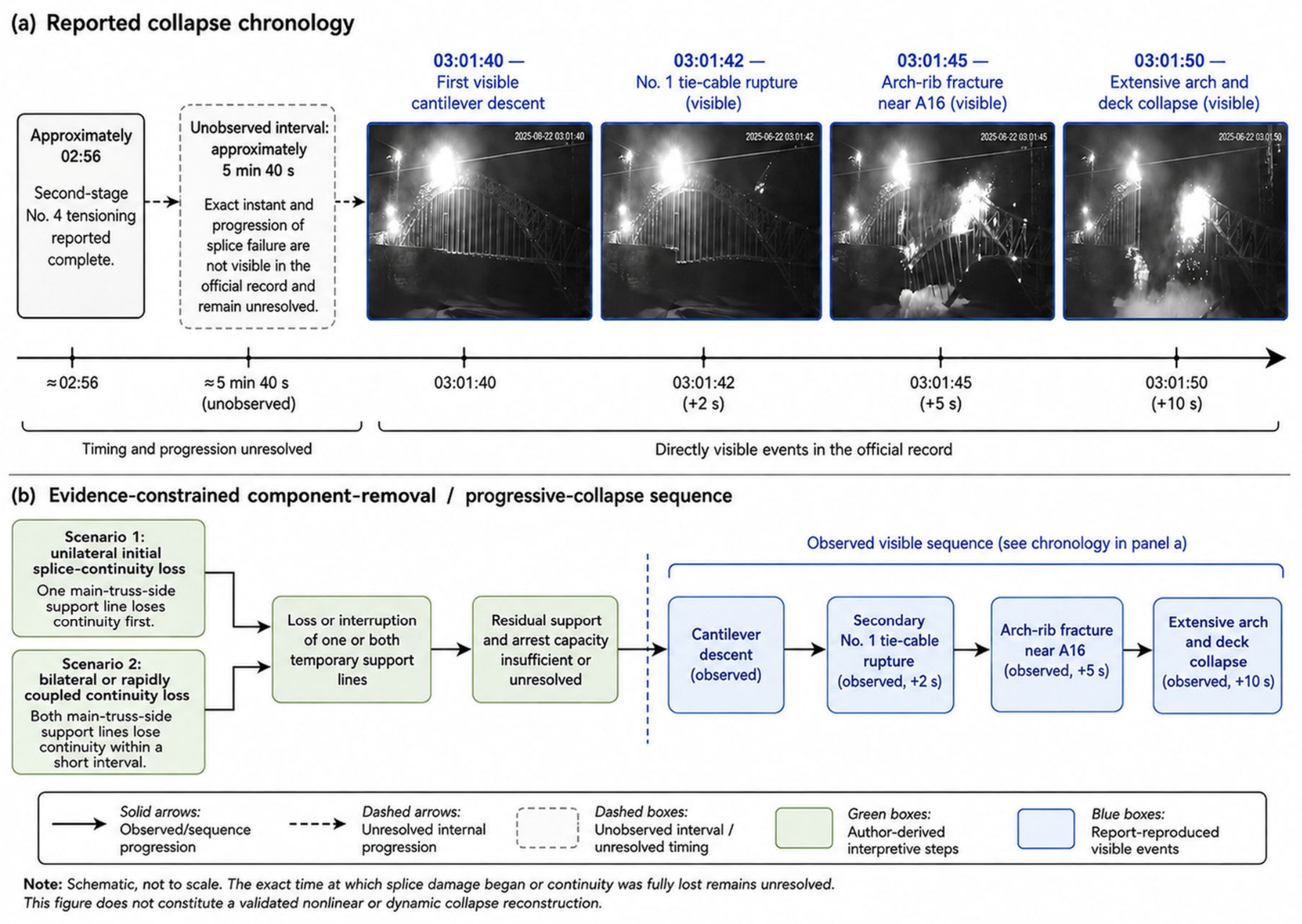
The chronology reproduced in the official investigation report is summarized in
Table 4 and visualized in
Figure 4a, while
Figure 4b presents the corresponding evidence-constrained component removal and progressive collapse sequence. Second-stage tensioning was reported complete at approximately 02:56, while the first visible cantilever descent occurred at 03:01:40. The No. 1 tie cable ruptured approximately 2 s after descent began, the arch rib fractured near A16 after approximately 5 s, and extensive collapse developed within approximately 10 s [
35]. The visible cable rupture is therefore interpreted as secondary to the already developing collapse and not as the initiating event.
The nominal interval between reported completion and first visible movement was approximately 5 min 40 s. Because the completion time was reported only to the minute and the relevant operational and deformation records were unavailable, this interval is treated only as a temporal bound; it does not establish when splice damage began, when continuity was fully lost, or whether progressive degradation occurred throughout the interval. Further mechanical interpretation is provided in
Section 4.5.
Figure 4 separates the report-reproduced visible chronology from the author-derived bounded component-removal scenarios.
The official investigation excluded earthquake, adverse weather, hydrological effects, inadequate lighting, cable over-tensioning, and initiating failure of the temporary tower, principal cables, anchorage beams, anchorages, or wedges [
35]. The collapse is therefore treated as a reported resistance-deficiency failure during an authorized construction operation rather than as a response to an extraordinary external action.
4.2. Initiating Component and Documented Splice Deficiencies
The official investigation identified bolt-group shear failure and separation at the tower-top distribution beam splice as the initiating physical event [
35]. The documented deficiencies comprised nonconforming bolt properties and dimensions, threads crossing the shear planes, enlarged and irregular holes, missing fasteners, and unauthorized welded modifications.
Table 5 distinguishes the intended connection condition, the documented as-installed condition, and the author’s mechanical interpretation.
The official investigation evaluated the splice through bolt-group shear resistance and explicitly treated the location of the threads at the splice-plate shear plane as a resistance-reducing deficiency [
35]. On this evidentiary basis, the present study treats the connection as a shear/bearing-type bolted splice for mechanical interpretation, rather than as a slip-resistant friction joint. The publicly available record does not provide the original bolt-preload records or a slip-resistance design calculation; therefore, the actual installation preload cannot be independently established. The distribution beam splice used M27 × 140 and M27 × 180 bolts specified or marked as property class 8.8. According to the material test results reproduced in the official investigation report, the recovered samples did not satisfy the requirements of GB/T 3098.1-2010 with respect to external dimensions, chemical composition, Vickers and Rockwell hardness, tensile strength, and shear strength [
35,
44]. The report-reproduced test results also exhibited substantial scatter, indicating inconsistent manufacturing quality rather than a uniform, predictable reduction in one property alone.
The ultimate tensile strengths reproduced in the official investigation report ranged from 583 to 630 MPa, with a mean value of 608.3 MPa. The corresponding converted design shear strength was reported as 234.5 MPa, approximately 27% below the applicable standard requirement. These values indicate that the installed fasteners could not provide the mechanical resistance assumed for compliant property class 8.8 bolts [
35].
A second deficiency concerned the length of the threaded portion. The threads extended into the splice-plate shear plane, whereas the design resistance had been based on the larger gross cross-sectional area of the unthreaded bolt shank. The investigation estimated that the effective area resisting shear was thereby reduced by approximately 20% [
35].
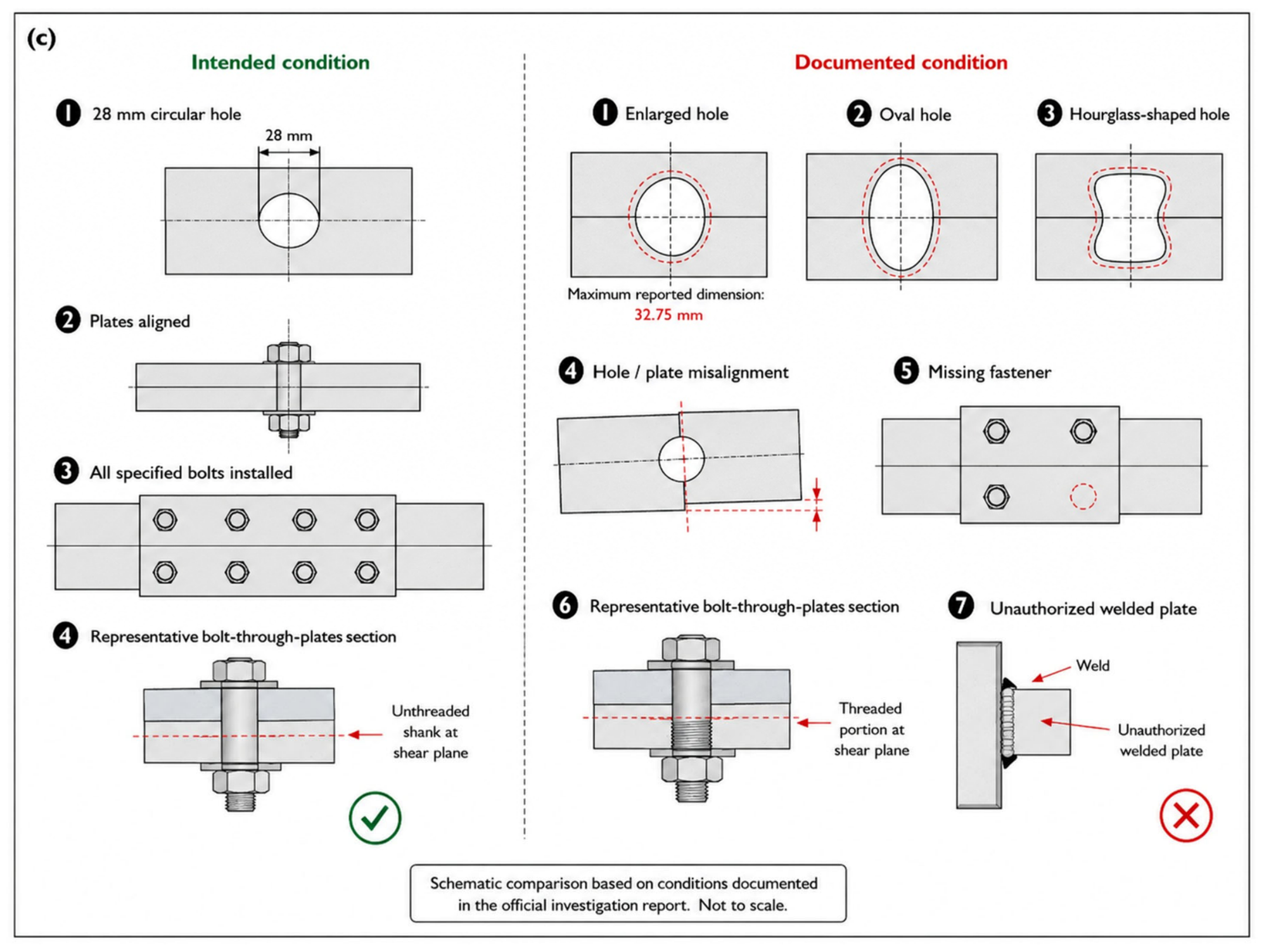
The investigation found that the flange plates, web plates, and splice plates had not been drilled in accordance with the design. Most holes exceeded the specified 28 mm diameter, substantial misalignment was addressed through field enlargement, and oval and hourglass-shaped openings were documented. The maximum measured hole dimension was 32.75 mm, which was 4.75 mm greater than the specified diameter, representing an approximate 17% increase [
35,
41,
45].
For the mechanical interpretation in this table, the splice is treated as a shear/bearing-type bolted connection on the basis of the bolt-group shear-resistance treatment reported in the official investigation [
35]. The intended and documented connection conditions are reproduced from the official investigation report [
35]. Unless otherwise stated, the mechanical implication column presents the author’s interpretation based on established connection mechanics. The gross M27 shank area of 572.6 mm
2 was calculated from the nominal bolt diameter, while the threaded area of approximately 459.4 mm
2 is a nominal standard value. The report-implied effective area of approximately 458.1 mm
2 was obtained by applying the reported 20% reduction in the gross shank area; it is not a measured shear-plane area. The normalized remaining resistance estimate and sensitivity range are author-derived and apply only to the reported material strength deficiency and threaded shear-plane area. They do not represent the resistance or failure capacity of the complete splice. The sensitivity range is illustrative and is not a statistical confidence interval.
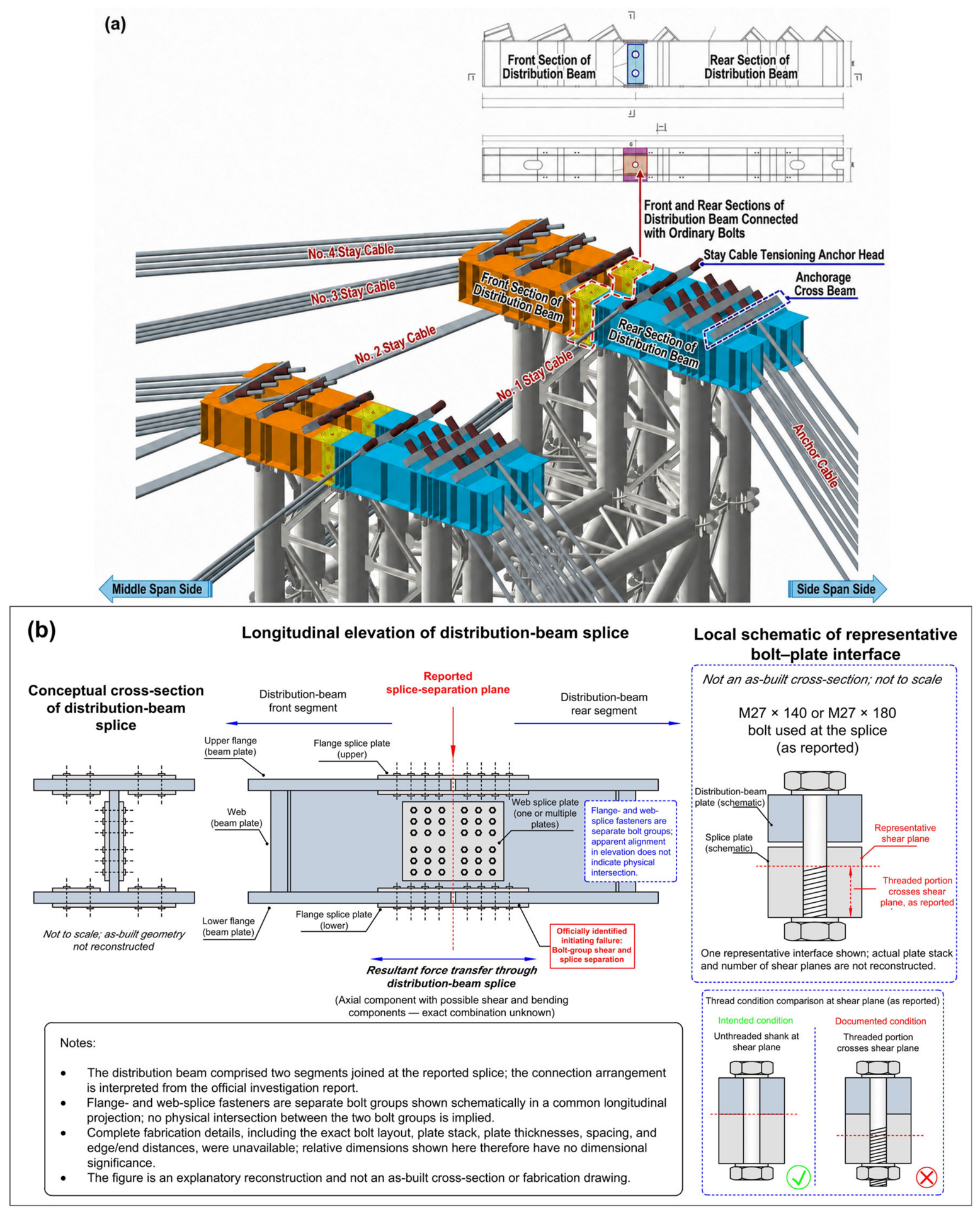
Figure 5 schematically relates the tower-top force-transfer arrangement to the reported distribution beam splice and documented connection deficiencies. Because complete fabrication drawings and the full as-built bolt-group geometry were unavailable, panels (b) and (c) are explanatory reconstructions only. In
Figure 5b, the flange- and web-splice fasteners represent separate bolt groups shown in a common longitudinal projection; their apparent alignment does not imply physical intersection. The enlarged local detail illustrates only the reported thread/shear plane condition of a representative bolt and does not reconstruct the as-built plate stack, number of shear planes, or relative plate thicknesses.
Variable hole clearance is mechanically significant because bolts in a bearing-type group engage only after local gaps between the bolt shanks and hole boundaries are closed. Differences in hole size, shape, and alignment can therefore cause sequential engagement, localized bearing, and nonuniform force sharing, while connector load-deformation behavior governs the extent of redistribution within the bolt group [
20,
21,
22]. Reynolds et al. [
20] reported average predicted strength reductions of approximately 9%, 14%, and 19% for the oversized-hole categories examined in their analytical study. These values cannot be transferred directly to the Jianzha splice, but they support the general interpretation that enlarged clearances can reduce bolt-group resistance. Because the Jianzha holes were irregular and varied between locations, simultaneous and uniform bolt engagement could not be assumed.
Missing bolts directly reduced the number of active fasteners and changed the stiffness and force distribution of the bolt group. The improvised welded plates could not be treated as verified strengthening because their geometry, weld properties, and force-transfer function were not incorporated into an approved revised design. The combined condition therefore differed materially from the connection idealized in the temporary works calculation.
4.3. Scope and Normalized Individual-Bolt Resistance Assessment
The purpose of this calculation is not to introduce a new bolted connection design method or to reconstruct the resistance of the failed splice. It provides a transparent bolt-level consistency check by combining, on the same normalized resistance term, the two quantitative deficiencies reported by the official investigation: reduced material strength and reduced resisting area where the threaded portion crossed the shear plane. Its relevance to the collapse interpretation is therefore limited but specific: it quantifies the combined degradation relative to the nominal individual-fastener assumption, while the accident-specific failure of the bolt group and splice remains an official investigation finding rather than an independently reproduced capacity calculation.
For the limited bolt-level comparison, the individual-bolt shear resistance term is expressed in a generalized form consistent with the applicable steel design provisions [
41,
45]:
where
is the individual-bolt shear resistance,
is the number of shear planes,
is the resisting area at the shear plane, and
is the design shear strength of the bolt material. For the normalized comparison,
and all other common resistance factors cancel, so the remaining resistance ratio depends on the ratio of material strength and resisting area.
For the design condition in which the unthreaded M27 shank intersects the shear plane, the gross shank area is calculated as follows:
For a standard M27 coarse thread, the nominal threaded stress area is approximately 459 mm
2 [
44]. This may also be calculated from:
where
mm and the coarse-thread pitch
mm, giving
=
. The resulting nominal area ratio is expressed as follows:
The official investigation described the threaded shear plane as producing an approximately 20% reduction in effective area [
35]. Applied to the gross shank area, this corresponds to a report-implied effective area of:
This value is effectively consistent with the nominal M27 threaded stress area. However, it should not be described as a measured area because the report-reproduced information did not include measured thread-root diameters or individual shear-plane area measurements.
The reported converted design shear strength was 234.5 MPa, approximately 27% below the applicable reference value [
35]. The normalized remaining strength ratio is therefore:
Because the shear resistance term in Equation (1) is proportional to the product
, the two reported reductions are combined multiplicatively:
The multiplication does not assume statistical independence between the two deficiencies. It follows algebraically from the product of material strength and resisting area, provided that both reported reductions apply to the same individual-bolt shear resistance term and that the other resistance factors remain unchanged.
Using the rounded ratios reported by the investigation:
The corresponding estimated individual-bolt shear resistance reduction is expressed as follows:
Using the nominal M27 area ratio of 459/572.6 rather than the rounded value of 0.80 gives a remaining resistance ratio of approximately 0.585, representing a reduction of approximately 41.5%. The calculation should therefore be interpreted as a central estimate of approximately 41–42% for the two quantified individual-bolt effects. This percentage is a normalized bolt-level resistance effect only and must not be interpreted as a reduction factor for the bolt group, complete splice, or distribution beam assembly.
The report-reproduced ultimate tensile strengths ranged from 583 to 630 MPa, with a mean of 608.3 MPa. If the converted shear strength is assumed to vary in direct proportion to the reported tensile strength range while the nominal area ratio is held constant, the estimated individual-bolt resistance reduction ranges from approximately 39.4% to 43.9%. This is an illustrative sensitivity range rather than a statistical confidence interval because the raw test dataset, specimen-level converted shear strengths, and measured shear-plane areas were unavailable.
The calculation does not quantify the resistance of the complete splice. Complete splice resistance additionally depends on the number and arrangement of installed bolts, the number of shear planes, bolt-group eccentricity, plate bearing, net-section and block-shear resistance, bolt pretension, friction and contact conditions, hole clearances and shapes, connection slip, missing fasteners, sequential bolt engagement, prying or secondary bending, and the resistance of the splice plates and connected beam segments. The information required to evaluate these limit states was not publicly available. For the same reason, an accident-specific shear demand for an individual bolt cannot be determined from the available evidence. The reported demands are available only at the force-path level for a single main truss side; distributing them among individual bolts would require the complete as-built bolt pattern and force-sharing state, which are unavailable. Accordingly, the normalized result is used in this study only as a bolt-level consistency check and is not used to infer bolt-group resistance, splice failure load, or the capacity–demand ratio of the as-built connection.
4.4. Capacity–Demand Context
Table 6 defines the structural scope and analytical role of the reported force quantities. These quantities provide the available demand context at the structural force-path level rather than at the individual-bolt level. The official report explicitly identifies 1112 tf as the revised maximum tie-cable force per main truss. Because the 1200, 1884, and 3120 tf quantities were compared with that value, the present study treats them as applying to one four-bundle main-truss-side force path; this remains an author-derived scope interpretation because the original monitoring instruction and calculations were unavailable.
Table 6.
Force scope and normalized capacity–demand framework for the critical No. 4 tensioning stage.
Table 6.
Force scope and normalized capacity–demand framework for the critical No. 4 tensioning stage.
| Quantity or Analytical Role | Force Path and Structural Scope | Reported or Derived Value | Normalized Comparison and Limit-State Meaning | Source, Evidence Status, and Uncertainty |
|---|
| Revised maximum tie-cable force for a single main truss; four No. 4 bundles transferring force to the associated tower-top distribution assembly | 1112 tf (10.90 MN) | . Design-stage demand, not measured accident force. | Explicitly reported per main truss in ref. [35]. Original construction-stage model unavailable. |
| Prescribed tensioning control target for one No. 4 main-truss-side cable set | 1200 tf (11.77 MN) | . | Reproduced from monitoring instruction JZHHQ-57 through ref. [35]. It is a control target, not a direct force measurement. The single main truss scope is author-interpreted. |
| Procedure-derived force level after the first tensioning stage for the same cable set | Approximately 804 tf (7.89 MN) | . Intended or inferred at operational level only. | Calculated from the reported 67% stage in ref. [35]. No direct cable force monitoring was undertaken. |
| Force in the same cable set following completion of second-stage tensioning | MN) | . | Official investigation conclusion based on jacking records, geometry, and third-party simulation [35]. Raw data and original simulation unavailable. |
| As-designed tower-top distribution beam assembly resisting No. 4 tension for one main-truss-side force path | 1884 tf (18.48 MN) | . Nominal design resistance only; not as-built splice resistance. | Reported in ref. [35]. Original calculation and precise component decomposition unavailable; the single main truss scope is author-interpreted. |
| Nominal resistance of the four-bundle No. 4 cable set assigned to one main truss | 3120 tf (30.60 MN) |
Cable resistance, not distribution beam or splice resistance. | Reported in ref. [35]. Original cable resistance calculation unavailable; the single main truss scope is author-interpreted. |
| Individual-bolt shear term considering only reported strength and threaded area effects | Central estimate: 0.585 retained; sensitivity range: 0.561–0.606 | Dimensionless bolt-level result. It cannot be applied directly to the 1884 tf distribution beam resistance. | Author-derived in Section 4.3 using report-reproduced inputs. Not a complete splice estimate. |
| Complete splice including bolt-group geometry, holes, missing bolts, plates, contact, eccentricity, and all applicable limit states | Not calculable from available information | cannot be calculated independently. Reported governing limit state: bolt-group shear and splice separation. | Official investigation concluded that applied demand exceeded realized resistance [35]. No independent complete splice calculation was possible. |
Using the common single main-truss side scope adopted in
Table 6, the revised design demand of 1112 tf corresponds to approximately 0.590 of the reported nominal distribution beam resistance (1112/1884) and 0.356 of the nominal No. 4 cable resistance (1112/3120). The 1200 tf monitoring control force corresponds to approximately 0.637 and 0.385 of these respective nominal resistances. Equivalently, the reported nominal distribution beam resistance was approximately 1.69 times the revised design demand and 1.57 times the monitoring control force, while the nominal cable resistance was approximately 2.81 and 2.60 times these respective demand levels. These ratios are nominal design-level comparisons only and do not represent the capacity–demand ratio of the as-built splice.
The numerical comparisons above show that both the revised design demand and the monitoring control force remained below the reported nominal distribution beam and cable resistances. They therefore support the distinction between the nominal design adequacy of the reported force-transfer system and the realized resistance of the defective as-built splice. They do not establish the adequacy of the as-installed connection or independently reproduce its failure capacity. Its complete resistance cannot be calculated from the available bolt-group geometry, plate, contact, and installation information. The conclusion that accident-stage demand exceeded realized splice resistance therefore remains attributable to the official investigation [
35].
4.5. Interpretation of the Unobserved Post-Tensioning Interval
The official investigation concluded that the defective splice failed following the authorized second-stage No. 4 tensioning operation [
35], but the available chronology does not establish when splice damage began or continuity was fully lost. The nominal 5 min 40 s interval is therefore treated only as an unobserved temporal bound and does not demonstrate progressive damage throughout that period. Given the documented hole clearances, irregular geometry, and bolt deficiencies, connection slip, sequential fastener engagement, localized bearing, nonuniform force sharing, and redistribution remain mechanically plausible [
20,
21,
22], but their occurrence, timing, and sequence cannot be established from the available evidence.
5. Failure Propagation and Robustness
This section interprets the reported collapse sequence through construction-stage load paths and component removal reasoning. It does not constitute a validated equilibrium, nonlinear, or dynamic reconstruction. The structural interpretation is nevertheless constrained by three quantitative observations available from the public record: (1) the nominal capacity–demand ratios summarized in
Table 6; (2) the normalized individual-bolt resistance assessment in
Section 4.3; and (3) the measured temporal ordering of the visible collapse events in
Table 4 and
Figure 4. These quantities are used as consistency checks on the proposed load-path interpretation rather than as inputs to a reconstructed global collapse model.
5.1. Load-Path Interruption and Transverse Uncertainty
The official investigation identified bolt-group shear failure and separation at the tower-top distribution beam splice as the initiating physical event and concluded that the accident-stage demand exceeded the realized resistance of the defective bolt group [
35]. In the pre-closure configuration, each main truss side was supported through a longitudinal sequence comprising tie-cable bundles, an upper anchorage beam, a tower-top distribution beam line and splice, and the associated tower leg. The backstays balanced the resulting tower action through the completed side-span system. In the author-derived load-path interpretation, loss of continuity at the officially identified splice would have interrupted at least one primary construction-stage support line while the gravity loads acting on the incomplete bridge remained.
The publicly available evidence does not establish whether the opposite main-truss-side line retained partial support temporarily, whether both splice lines lost continuity nearly simultaneously, or whether unilateral loss rapidly propagated through transverse coupling. Accordingly, the manuscript does not claim that one splice failure instantaneously removed every cable force. The narrower evidence-supported conclusion is that the visible descent was not arrested before subsequent failures developed; whether a residual path existed briefly, how much force it retained, and when any remaining support became insufficient remain unresolved.
The bounded splice loss scenarios can therefore be stated quantitatively only in topological, rather than force distribution, terms. Before continuity loss, two main-truss-side longitudinal support lines are represented in the accident-stage topology. Under the unilateral bounding case, continuity is lost in one of these two lines while the status and residual force of the opposite line remain unresolved. Under the bilateral- or rapidly coupled bounding case, continuity is lost in both lines. These states should not be interpreted as 50% and 100% reductions in structural resistance or cable force because the force carried by each line and the transverse redistribution between them cannot be reconstructed from the available evidence.
5.2. Visible Propagation
The report-reproduced chronology records the first visible cantilever descent at 03:01:40, followed by rupture of the No. 1 tie cable approximately 2 s later, arch-rib fracture near A16 at approximately +5 s, and extensive collapse by approximately +10 s [
35]. Because structural movement preceded cable rupture, the cable failure is interpreted as secondary rather than initiating. These times constrain the visible propagation sequence but do not permit the associated transient member forces or dynamic amplification to be quantified.
The available records do not permit a quantitative explanation of why fracture localized near A16. Member force histories, sectional and connection properties at A16, lateral restraint and bracing characteristics, initial geometric imperfections, fracture-surface evidence, local deformation measurements, and the displacement–time history were unavailable. Although lateral or out-of-plane buckling was not identified as a mechanism in the official investigation, the compressive role that an upper arch member may experience during the evolving construction-stage collapse means that such instability could plausibly have amplified local bending and deformation near A16 after the initial loss of support. Axial force redistribution, bending, lateral or local instability, connection deformation, and impact are therefore retained as possible secondary contributors rather than assigned quantified causal roles.
If splice continuity was initially lost on only one main truss side, the resulting difference in vertical restraint could have generated differential cantilever displacement, transverse force redistribution, and torsional or warping demand in the arch, deck, and connecting bracing. Such a response is mechanically plausible but is not established as a causal contributor because the side-specific release sequence, transverse stiffness, torsional coupling, cable force histories, and displacement–time records are unavailable. A bilateral- or rapidly coupled loss remains equally unresolved. No quantitative magnitude or causal weight is therefore assigned to torsional response.
5.3. Component Removal and Robustness Interpretation
The qualitative component-removal assessment asks whether the incomplete bridge could continue carrying its construction-stage actions after the loss of splice continuity. The two bounded initiation cases and their convergence into the report-reproduced visible collapse sequence are summarized in
Figure 4b. The documented sequence is mechanically consistent with interruption of at least one primary main-truss-side support line, insufficient residual support or arrest response, cantilever descent, secondary cable and arch-rib failures, and disproportionate collapse. This assessment establishes pathway consistency only; it does not calculate residual capacity, member demand, collapse time, or dynamic amplification. Component-removal analysis is an established scenario-based approach for examining structural robustness after localized damage, but its conclusions depend on the assumed removal scenario, structural continuity, dynamic effects, and available residual load paths [
5,
6,
23,
24,
25].
Taken together, the quantitative checks constrain—but do not uniquely reconstruct—the collapse mechanism. The revised design demand and monitoring control force were approximately 59.0% and 63.7%, respectively, of the reported nominal distribution beam resistance, indicating that the authorized loading level was below the reported nominal resistance of the as-designed assembly. Independently, the bolt-level normalization confirms that the two quantified fastener deficiencies act cumulatively to reduce the individual-bolt shear resistance term relative to its nominal reference; this result is used only as a consistency check and cannot be extended to complete splice resistance. Finally, the observed chronology establishes that global movement preceded cable rupture by approximately 2 s and that major structural propagation occurred within approximately 10 s. These three quantitative observations are mutually consistent with the official finding that a deficient splice lost continuity under an authorized construction-stage loading condition and with the subsequent load-path interpretation developed here. They do not determine whether continuity loss was initially unilateral or bilateral, quantify the residual force in the opposite support line, or reproduce the nonlinear collapse response.
Together, these checks support only a bounded robustness inference: the officially identified splice separation is mechanically consistent with the interruption of at least one main-truss-side temporary support line, while the residual support state, the initial mode of continuity loss (unilateral, bilateral, or rapidly coupled), and the nonlinear collapse response remain unresolved.
The official chronology and reported damage observations were used to assess whether the documented sequence was mechanically consistent with the loss of the distribution beam splice and subsequent collapse propagation; the assessment was not intended to reproduce the exact nonlinear response. The available data were screened for simplified quantitative analysis, but the public record did not provide the accident-stage cable inclinations, panel-by-panel self-weight and erection loads, member sectional properties and joint stiffnesses, transverse coupling characteristics, time history or symmetry of support loss, or displacement–time data. Consequently, the quantitative assessment was limited to evidence-supported capacity–demand ratios, individual-bolt normalization, event timing, and load-path topology. Analyses of accident-specific equilibrium, cantilever bending demand, A16 fracture demand and lateral stability/buckling, dynamic amplification, asymmetric support loss, and nonlinear staged-construction response were not attempted because they would require assumptions for critical quantities unavailable in the public record. Numerical results based principally on such assumed values would create false precision rather than accident-specific evidence.
8. Recommendations
Section 8 distinguishes accident-specific measures, established practices, and study-specific procedural refinements. The latter operationalize the barrier pathways identified in
Section 6.5 through safety-critical component classification, complete local-detail verification, field-deviation hold points, formal load-transfer release, monitoring thresholds, robustness checks, assigned authority, and personnel exclusion. Implementation and verification requirements are specified below, with monitoring treated as supplementary to preventive controls.
8.1. Temporary Works Classification and Independent Verification
Temporary components should be classified according to their structural role and failure consequence, while the target reliability for a temporary construction stage should also account for its limited exposure duration. A temporary tower, cable, anchorage beam, distribution beam, splice, support, or backstay should be designated safety-critical where its loss could destabilize a substantial part of the incomplete bridge. Shorter exposure may justify a lower target reliability than that adopted for permanent design situations where supported by the applicable reliability framework; however, the selected reliability level should remain commensurate with the consequences of failure, personnel exposure, and the criticality of the supported structure. Accordingly, design, fabrication, testing, inspection, acceptance, and monitoring requirements should be proportionate to the construction-stage risk rather than automatically equated with those for primary permanent members. The consequence-based reliability principle itself is established practice. The accident-specific procedural refinement proposed here is that the project should maintain an explicit register of safety-critical temporary components and connections, identified by the consequence of their loss, with the required level of analysis, checking, inspection, and release defined before those components enter service.
Construction-stage verification should represent the actual sequence, member activation, temporary loads, erection equipment, geometric nonlinearity, connection flexibility, asymmetric conditions, and credible component-loss scenarios. Independent checking should include local force-transfer zones, bolt groups, splice plates, diaphragms, anchorage assemblies, temporary bearings, and foundations rather than being limited to the global model.
8.2. Connection Quality, Fit-Up, and Hold Points
Safety-critical bolted connections should be verified as complete joint systems, including fastener material properties, thread position, hole geometry, plate contact, pretension where applicable, bearing, slip, eccentricity, and sequential engagement. Quality control should include batch-level traceability, independent mechanical testing, dimensional inspection, confirmation of installed bolt number and position, and inspection of safety-critical welds.
Material traceability, connection verification, and dimensional inspection are established quality control principles. The Jianzha-specific refinement proposed here is to convert any unresolved fit-up deviation in a safety-critical connection into a mandatory engineering hold point rather than permitting field accommodation without documented reassessment.
Fit-up problems—including hole mismatch, abnormal gaps, unexpected deformation, or inability to install specified fasteners—should trigger suspension, stabilization, as-built surveying, updated analysis, and written approval of an engineered corrective procedure. Uncontrolled hole enlargement, bolt omission, forced assembly, and improvised welding should be prohibited. Mandatory hold points should be established before use of temporary towers and critical splices, before major tensioning stages, during load transfer, and before closure.
8.3. Monitoring, Load Transfer, and Personnel Safety
Monitoring should supplement rather than replace procurement, testing, fabrication inspection, and formal acceptance. Global quantities such as cable force, cantilever geometry, and tower inclination should be combined, where practicable, with local strain, splice opening or slip, and connection-zone response. Stage-specific models should establish expected ranges and alert, action, and stop-work thresholds before loading begins.
Construction-stage monitoring and response verification are supported by established monitoring practice and literature. The specific refinement proposed here is the use of a formal hold-and-transfer gate after critical tensioning, so that operational completion is not defined solely by cessation of jacking or attainment of geometry but by documented confirmation of force transfer and response stability.
Critical tensioning should proceed incrementally, with verified structural response before each subsequent load step. Completion should include a documented hold-and-transfer stage covering cessation of pumping, pressure holding, unloading, lock-off, transferred cable force, and response stability. Personnel should remain outside defined zones for collapse, falling objects, and cable recoils until transfer and stabilization are confirmed. Remote operation and automatic alarms or pump interlocks should be considered where communication and response delays could prevent timely intervention.
8.4. Robustness and Responsibility
Component-removal assessment should examine loss of cables, backstays, distribution beam splices, bolt rows, anchorage groups, temporary supports, and bracing. Where practical redundancy cannot be provided, passive arrest measures, enhanced verification, monitoring, and personnel exclusion should be required. Consequence-limiting measures should not depend on manual intervention after visible movement begins.
Component-removal and robustness assessments are established structural safety concepts. The accident-specific extension proposed here is to apply them explicitly to safety-critical temporary support paths and to link the resulting loss scenarios to both structural arrest provisions and personnel exposure controls before the relevant construction stage is authorized.
A project-specific responsibility matrix should assign authority for temporary system design, independent checking, supplier qualification, material testing, fabrication approval, field modifications, inspection, monitoring review, hold point release, tensioning authorization, and stop-work decisions. Safety-critical verification should not depend on informal assumptions that another organization has completed the required control.
Implementation should be verified through auditable project records rather than through general statements of compliance. For safety-critical temporary works, the minimum evidence should include a component criticality register; signed independent check records covering both global and local details; material certificates and batch mechanical test results; as-built dimensional and fastener installation records; documented engineering dispositions for field deviations; signed hold point and load-transfer release records; monitoring thresholds and response logs; component-removal or equivalent robustness assessments; personnel exclusion and remote operation plans where applicable; and a responsibility matrix identifying the individuals authorized to approve, release, suspend, or restart critical operations. Progression to the next safety-critical construction stage should require documented closure of the applicable controls.
9. Conclusions
This document-based study treats the official investigation as the controlling source for accident-specific findings; those findings are not claimed as original. Load-path tracing and conventional bolted connection mechanics are likewise not presented as novel methods. The contribution lies in the evidence-graded integration of the reported evidence with author-derived quantitative checks, load-path and topology interpretation, chronology, bounded robustness assessment, and safety barrier synthesis to derive transferable temporary works lessons.
The official investigation identified bolt-group shear failure and separation at the tower-top distribution beam splice as the initiating physical event. The bolt-level normalization developed here shows only that the reported material strength deficiency and threaded shear plane act cumulatively to reduce individual-fastener resistance; it does not quantify bolt-group or complete splice capacity. Before arch closure, the splice occupied a primary temporary support path. Visible cantilever descent preceded cable rupture by approximately 2 s, arch-rib fracture occurred at approximately +5 s, and extensive collapse developed by approximately +10 s. The nominal 5 min 40 s pre-movement interval is only a temporal bound; the onset of splice damage and whether continuity loss was initially unilateral or bilateral remain unresolved.
The fault-tree and bow-tie synthesis organizes the reported technical and organizational deficiencies as failed preventive or detective controls and distinguishes alternative support and personnel exclusion as consequence-limiting controls. It identifies where the documented pathway could have been interrupted without assigning probabilities or quantitative importance. The historical comparison supports only a bounded mechanism-level conclusion: localized weakness in a consequential construction-stage load path can produce disproportionate collapse where redistribution or arrest capacity is insufficient.
The principal engineering implication is that temporary components should be governed by their structural role and failure consequence, while construction-stage reliability should also reflect exposure duration and project-specific risk. Safety-critical temporary works require stage-specific global and local verification, traceable materials, controlled fabrication and fit-up, formal hold points, supplementary monitoring, robustness assessment, clear responsibility, and personnel exclusion. Complete validation of the accident mechanism would require access to the original model, drawings, monitoring and test data, footage, and recovered components.