Article

Development of an Integrated 3D Simulation Model for Metro-Induced Ground Vibrations

1
Department of Mechanical and Industrial Engineering, Qatar University, Doha P.O. Box 2713, Qatar
2
Department of Civil and Environmental Engineering, Qatar University, Doha P.O. Box 2713, Qatar
*
Author to whom correspondence should be addressed.
Infrastructures 2025, 10(9), 253; https://doi.org/10.3390/infrastructures10090253
Submission received: 19 July 2025 / Revised: 4 September 2025 / Accepted: 11 September 2025 / Published: 21 September 2025
(This article belongs to the Section Infrastructures and Structural Engineering)

Abstract

This paper introduces a novel 3D simulation framework that integrates the Pipe-in-Pipe (PiP) model with Finite Element Analysis (FEA) using Ansys Parametric Design Language (APDL). This framework is designed to incorporate a 3D building model directly, assessing ground-borne vibrations from metro tunnels and their impact on surrounding structures. The PiP model efficiently calculates displacement fields around tunnels in full-space, applying the resulting fictitious forces to the FEA model, which includes a directly coupled 3D building model. This integration allows for precise simulation of vibration propagation through soil into buildings. A comprehensive verification test confirmed the model’s accuracy and reliability, demonstrating that the hybrid PiP-FEA model achieves significant computational savings-approximately 40% in time and 65% in memory usage-compared to the traditional full 3D FEA model. The results exhibit strong agreement between the PiP-FEA and full FEA models across a frequency range of 1–250 Hz, with less than 1% deviation, highlighting the effectiveness of the PiP-FEA approach in capturing the dynamic behavior of ground-borne vibrations. Additionally, the methodology developed in this paper extends beyond the specific case study presented and shows potential for application to various urban vibration scenarios. While the current validation is limited to numerical comparisons, future work will incorporate field data to further support the framework’s applicability under real metro-induced vibration conditions.

1. Introduction

As metro systems expand in cities, they bring both convenience and challenges, particularly related to ground-borne vibrations. These vibrations, caused by trains running through underground tunnels, can spread through the ground and affect nearby buildings. While the risk of structural damage is generally low, they can create discomfort for residents, leading to issues like sleep disturbances and stress [1]. Several factors influence how vibrations travel, including the depth of the tunnel, soil type, train speed, and track conditions. In busy urban areas, where multiple rail systems often operate together, vibrations can be more intense, making it important to predict and manage their effects. One of the main ways researchers study this problem is by using numerical modeling. Finite element methods (FEM) have been applied to study vibrations from tunnels into the ground and nearby buildings; for example, FE models with perfectly matched layers (PML) have been developed to improve boundary absorption and simulation accuracy [2].The Pipe-in-Pipe (PiP) model is a popular tool for simplifying this process. It treats the tunnel and the surrounding soil as layers of concentric cylinders, which helps researchers understand how vibrations travel through different materials [3]. While the PiP model is efficient for studying the immediate effects of vibrations near the tunnel, it cannot by itself capture the structural dynamics of buildings subjected to ground-borne vibrations. To realistically assess vibration impacts on buildings, a numerical building representation is indispensable. Among available numerical methods, the Finite Element Method (FEM) is particularly suitable because it directly models complex 3D geometries, soil-structure interactions, and building-specific features. Alternative semi-analytical approaches such as 2.5-D FE-BE or periodic FE-IFE are efficient for soil wave propagation problems but cannot easily incorporate realistic building geometries or localized structural responses. Therefore, coupling PiP with FEM provides a balanced framework: PiP efficiently represents the tunnel-soil interaction, while FEM ensures that building vibration responses are modeled with the required accuracy and detail [4]. Real-world studies have backed up these models by comparing their results with actual data. For instance, tests on train vibrations in Shanghai have shown how vibrations from both ground and subway trains can increase the overall impact on the area [5]. Other studies of metro depots have found that office and residential buildings react differently to low frequency vibrations [6]. Despite these advances, there are still challenges in predicting and managing ground-borne vibrations. Differences in soil layers and the combined effects of multiple train systems make it hard to create accurate models [7]. Furthermore, the interactions between the tunnel, track, and surrounding soil are crucial for understanding ground-borne vibrations; however, existing models often oversimplify these dynamics, which can lead to inaccurate predictions of vibration behavior [8]. However, accurately predicting and mitigating ground-borne vibrations remains challenging due to the limitation of current models in handling complex building structures. This study aims to address this challenge by improving the accuracy and computational efficiency of vibration simulations, offering a practical solution to deal with ground-borne vibrations in buildings.

2. Literature Review

2.1. Analytical Models

Researchers have developed analytical and semi-analytical formulations to simulate ground-borne vibrations from tunnels. These approaches provide benchmark or efficient solutions for tunnel-soil interaction problems but do not rely on finite element discretization. Examples include benchmark half-space solutions [9], analytical formulations for multi-layered soil media [10,11,12], and extensions to unsaturated or shallowly buried tunnel cases [13,14]. Such models are valuable for capturing fundamental wave propagation mechanisms and for validating more complex numerical approaches; however, they often simplify soil-structure interaction and cannot easily incorporate realistic above-ground building geometries.

2.2. Semi-Analytical Models

Similarly, the research by [4], presented an extension of the Pipe-in-Pipe (PiP) model that allows for the incorporation of a multi-layered half-space. This model efficiently calculates vibrations by first using a full-space tunnel model to determine displacements at the tunnel-soil interface and then applying equivalent loads to a multi-layered half-space. The approach maintains computational efficiency while accurately predicting vibrations from underground tunnels, making it a valuable tool in early-stage design for vibration mitigation measures. The fictitious-force method has likewise been referenced and extended in later studies. The research by [15] applied the approach to investigate ground vibrations from circular tunnels. The study by [16] introduced an efficient poroelastic half-space predictor citing the FFM formulation. The work by [17] integrated similar fictitious-force concepts into the Scope Rail prediction tool for building vibrations near high-speed rail. Recent studies have also proposed hybrid semi-analytical/numerical frameworks, such as the periodic FE-BE approach for twin tunnels incorporating fictitious-force concepts [18]. Furthermore, the methodology by [19] proposed a hybrid approach to address soil-structure interaction (SSI) challenges, where the ground and structure are modeled separately but connected to ensure equilibrium and compatibility conditions. This sub-structured approach, while computationally efficient, still captures the complex dynamics of vibration transmission, making it valuable for ground-borne vibration analysis.
The PiP model, commonly used in metro tunnel simulations, remains instrumental in these studies. It simulates the dynamic response of tunnels under moving train loads by treating tunnels as combinations of inner and outer pipes [3]. By coupling the PiP model with other models, previous research has demonstrated improvements in predicting how vibrations propagate through different layers of soil and structural elements. This hybrid approach has been applied to underground metro systems, particularly in deep-buried tunnels, where soil-structure interactions are complex but vital for determining the dynamic behavior of the system. Ground vibration modeling has evolved with several advanced techniques, and the combination of PiP and other models has enhanced the understanding of vibration propagation in urban environments. Notably, the use of PiP models offers simplified yet effective simulation of tunnel-soil systems, but this method still falls short when it comes to integrating building dynamics into the vibration analysis, a crucial aspect in urban settings [20,21].

2.3. Numerical Models

Ground-borne vibrations caused by urban rail transit systems have been extensively studied due to their significant impact on nearby buildings and human comfort. Researchers used field measurements to assess the noise and vibration impacts of urban rail transit in Tianjin, China, showing that wheel-rail polishing and train speed reduction could mitigate indoor vibrations by up to 6 dB, with effectiveness varying by frequency [1]. Similarly, involving field tests and numerical simulations on train-induced vibrations at metro depots highlighted the importance of understanding vibration transmission pathways [22]. Several studies have aimed to improve prediction accuracy by integrating numerical modeling with empirical validation. For instance, combining centrifuge testing with numerical modeling to explore the effects of soil non-homogeneity on ground-borne vibrations from underground tunnels, underlines the need to account for varying soil properties with depth [22]. The study by [23] used both centrifuge and numerical modeling to investigate ground-borne vibrations from surface sources, with a specific focus on the variation in soil properties with depth, known as soil non-homogeneity. They demonstrated that accounting for the changing stiffness and damping of soil with increasing confining stress is crucial for accurately predicting ground-borne vibrations, particularly from surface foundations. Their work highlights the importance of considering soil non-homogeneity in both experimental and numerical simulations to ensure accurate results when studying vibration propagation [23]. Similarly, a study by [24] combined numerical simulations with experimental field measurements to predict building vibrations caused by subway trains. The findings highlighted the potential of using Z-vibration levels at the ground surface as input for machine learning-based predictive models, which offered faster and more accurate vibration predictions.
Furthermore, the work by [25] presented a 2.5D finite element method (FEM) as an alternative to full 3D models, which reduces computational load while maintaining accuracy in predicting ground-borne vibrations for shallow foundation buildings. While 3D models are often more accurate, they are computationally expensive, and their simplifications can result in trade-offs in certain conditions, such as variations in soil properties and tunnel depth. The work by [3] developed a 3D tunnel model to calculate train-induced ground vibrations, significantly advancing the understanding of vibration dynamics in urban settings. Subsequent independent studies have also applied or validated the PiP framework. One study [26] demonstrated its application for predicting ground-borne vibrations above cross-rail construction tunnels. Another work [27] developed a computationally efficient 2.5D Green’s function model in layered half-spaces building on PiP concepts. Further research [28] adapted the PiP model to consider more complex tunnel-soil interaction features, extending its use to cases with soil inhomogeneity and multiple tunnels. To overcome the computational limitations of fully 3D models, hybrid approaches combining FEA and boundary element methods (BEM) have been proposed. For instance, the work by [29] used a 3D FEM-BEM approach to simulate vibrations, capturing complex vibration patterns in high-speed railway systems. The work by [30], introduced a substructure simulation approach to analyze the dynamic interaction between tracks and layered ground. The authors in [31], compared two different numerical models for predicting vibrations from underground railways: the PiP model and the coupled periodic FE-BE model. While the PiP model offered computational efficiency and a good representation of tunnel-soil interactions, it was limited to simple geometries and homogeneous soil. In contrast, the coupled periodic FE-BE model allowed for more detailed simulation of complex geometries and soil layers, though at a higher computational cost [31]. Recent studies have focused on validating these models with real-world data to demonstrate and ensure their utility. For example, ref. [32] conducted field experiments to measure vibrations caused by subway and road traffic systems, providing essential empirical data for validating simulation models of ground-borne vibrations. Similarly, a study by [33], investigated the effects of using softer rail-pads in the Doha Metro system on vibration levels at the free surface and within the railway tunnel. They found that replacing the conventional stiffer rail-pads with softer web-supporting pads reduced vibration levels by approximately 10 dB for frequencies between 40 and 200 Hz- at the free surface, with higher attenuation observed between 45 and 65 Hz-. This work highlighted the potential for softer rail-pads to serve as an effective vibration mitigation strategy for underground railways. These findings are particularly relevant for environments with multiple interacting sources of vibration. Moreover, a study focused on high-speed train-induced vibrations in ballasted railway tracks used 3D numerical simulations to quantify peak particle velocities (PPVs) at various points within the track and surrounding soil [34].
While many numerical models offer a relatively simplified approach to vibration prediction, certain environmental and structural aspects are often overlooked, leading to the underestimation of vibration levels. Six commonly disregarded factors include the presence of a second (twin) tunnel, piled foundations, discontinuous slab tracks, soil inhomogeneity, inclined soil layers, and irregular contact at the tunnel-soil interface. These factors can cause deviations in predicted vibration levels by as much as 5 dB to 20 dB compared to simplified models, highlighting significant uncertainty in the predictions [35]. Moreover, researchers demonstrated that the uncertainty in predicting railway-induced ground-borne vibrations could reach up to ±10 dB due to small variations in soil properties, slab stiffness, and measurement positions [36]. However, existing studies often focus on simplifying 3D models to 2.5D to reduce computational complexity. However, this can come at the cost of reduced accuracy under certain conditions, such as variations in soil properties and tunnel depth [25]. Moreover, the application of 2.5D and hybrid FE-BE methods has shown potential in accurately predicting vibrations while maintaining manageable computational loads. However, these studies commonly disregard the full three-dimensional dynamic responses of buildings to these vibrations, focusing instead on the soil and tunnel interactions [37,38,39]. The dynamic interaction of urban railway systems with their environment has been extensively studied, with a focus on mitigating vibrations through a variety of modeling techniques. Notably, the use of PiP models offers simplified yet effective simulation of tunnel-soil systems, but this method still falls short when it comes to integrating building dynamics into vibration analysis, a crucial aspect in urban settings [40,41]. The need for a more holistic approach is evident, as studies have increasingly pointed to the limitations of existing methodologies in fully capturing the complex dynamics of urban environments [42,43]. More advanced numerical studies have focused on integrated soil-tunnel-building dynamics, where both the tunnel-soil system and the above-ground structures are modeled within a unified framework [44,45,46]. These approaches capture the mutual interaction between building vibration response and ground wave propagation, offering a more realistic prediction of real world applications. For example, a study in [47] emphasized that simplified soil-tunnel-building interaction models could lead to underestimation of vibration amplitudes, especially in cases involving flexible superstructures. They demonstrated that incorporating a full 3D building model significantly altered the dynamic response of the system, particularly at higher frequency ranges above 50 Hz. Similarly, the study in [46] analyzed cross-tunnel interaction under dynamic loading and concluded that the mutual influence of adjacent tunnels and aboveground buildings cannot be neglected in dense urban environments, as it alters the stress distribution in the surrounding soil and affects vibration propagation paths. Moreover, the researchers in [47] developed a frequency-dependent soil-tunnel-foundation interaction model and showed that dynamic impedance functions vary significantly with building height and stiffness, emphasizing the need for integrated modeling approaches.

2.4. Innovation Statement

The use of the Pipe-in-Pipe (PiP) model, despite its representation of infinitely invariant conditions, is chosen for its computational efficiency and robustness in handling complex tunnel geometries and soil interactions. This is crucial as PiP models integrate well with finite element methods (FEM), which model the surrounding buildings and soil using discrete elements. This hybrid modeling approach addresses the incompatibility between the infinite conditions of PiP and the finite elements of building models by ensuring that both models work cohesively to predict vibrations accurately. This study introduces a 3D simulation framework that enhances the PiP model’s computational efficiency by integrating it with Finite Element Analysis (FEA) to include a detailed 3D model of actual building structures. The hybrid PiP-FE model is particularly valued for its speed and reliability in early-stage design and vibration mitigation strategies crucial for rapid predictions in large areas with underground tunnel systems. This approach not only reduces computational demands but also effectively incorporates multi-story buildings, addressing a significant oversight in previous research. By leveraging the strengths of both PiP and FEA, this methodology provides a comprehensive understanding of how vibrations from metro tunnels propagate through soil into buildings, allowing for precise predictions of their impacts. Moreover, the adaptability of this framework ensures that it can be applied to other modeling scenarios, making it a versatile tool for other applications related to ground-borne vibrations.
The paper is structured as follows: Section 3 outlines the methodology, including the integration of the PiP model with FEA using APDL. Section 4 presents the 3D simulation results, focusing on vibration propagation through soil and buildings. Section 5 compares the PiP-FEA model with fully detailed 3D simulations to validate its efficiency and accuracy. Finally, Section 6 and Section 7 discuss and conclude with key findings and recommendations for future research.
3. Methodology

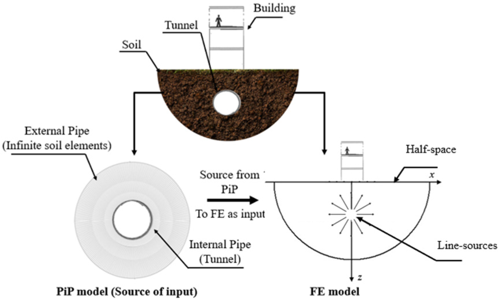
This research employs a comprehensive 3D simulation framework that integrates the PiP model with FEA using APDL to analyze the propagation of metro-induced ground vibrations and their impact on adjacent buildings. This approach allows for a detailed examination of vibration transmission from underground metro tunnels to surrounding buildings, enabling more precise predictions and effective mitigation strategies. The schematic in Figure 1 shows the integration of the PiP model with the FE model. The PiP model simulates the source of vibrations in the tunnel and transfers the input forces to the FE model, where the propagation of vibrations through the soil and into the building structure is analyzed. The external pipe represents the infinite soil elements, and the internal pipe models the tunnel vibrations, which are used as inputs for the FE analysis in APDL. The half-space model captures the transmission of vibrations through the soil to the building.

3.1. Simulation Setup: Pipe-in-Pipe (PiP) Model

The methodology begins with the PiP model, which has been adapted to simulate the transmission of vibrational energy generated by metro trains. In this study, the PiP model simulates the vibration source using a transfer function applied within the metro tunnel, representing the dynamic forces produced by metro trains. This vibration is transmitted through the tunnel walls and into the surrounding soil, which is modeled as an external pipe. The PiP model efficiently represents the transfer of vibrational energy from the tunnel structure to the adjacent soil, capturing both pressure and shear waves in the soil medium. Originally developed for full-space scenarios, the PiP model has been extended to account for more realistic conditions, such as multi-layered half-spaces. By using the fictitious force method, the PiP model approximates how vibrations propagate in layered soils while maintaining computational efficiency. This adaptation allows the PiP model to simulate real-world conditions, where soil properties and tunnel depth vary significantly, enhancing its applicability to complex structural buildings [4]. By incorporating soil properties such as stiffness, damping, and inhomogeneity, the model captures the initial phase of vibration propagation while accounting for critical factors like tunnel geometry and soil-tunnel interaction. Factors such as soil inhomogeneity and depth variations are incorporated to ensure accurate representation of ground-borne vibration transmission. The validation of the PiP model against more computationally intensive Finite FE-BE models has demonstrated good agreement while preserving computational efficiency [4].
The plot in Figure 2 shows a single fictitious point force load with force components along the X, Y, and Z directions, derived from the PiP model. These forces are input into APDL as point loads to simulate the interaction of vibrational energy with the soil and nearby structures.
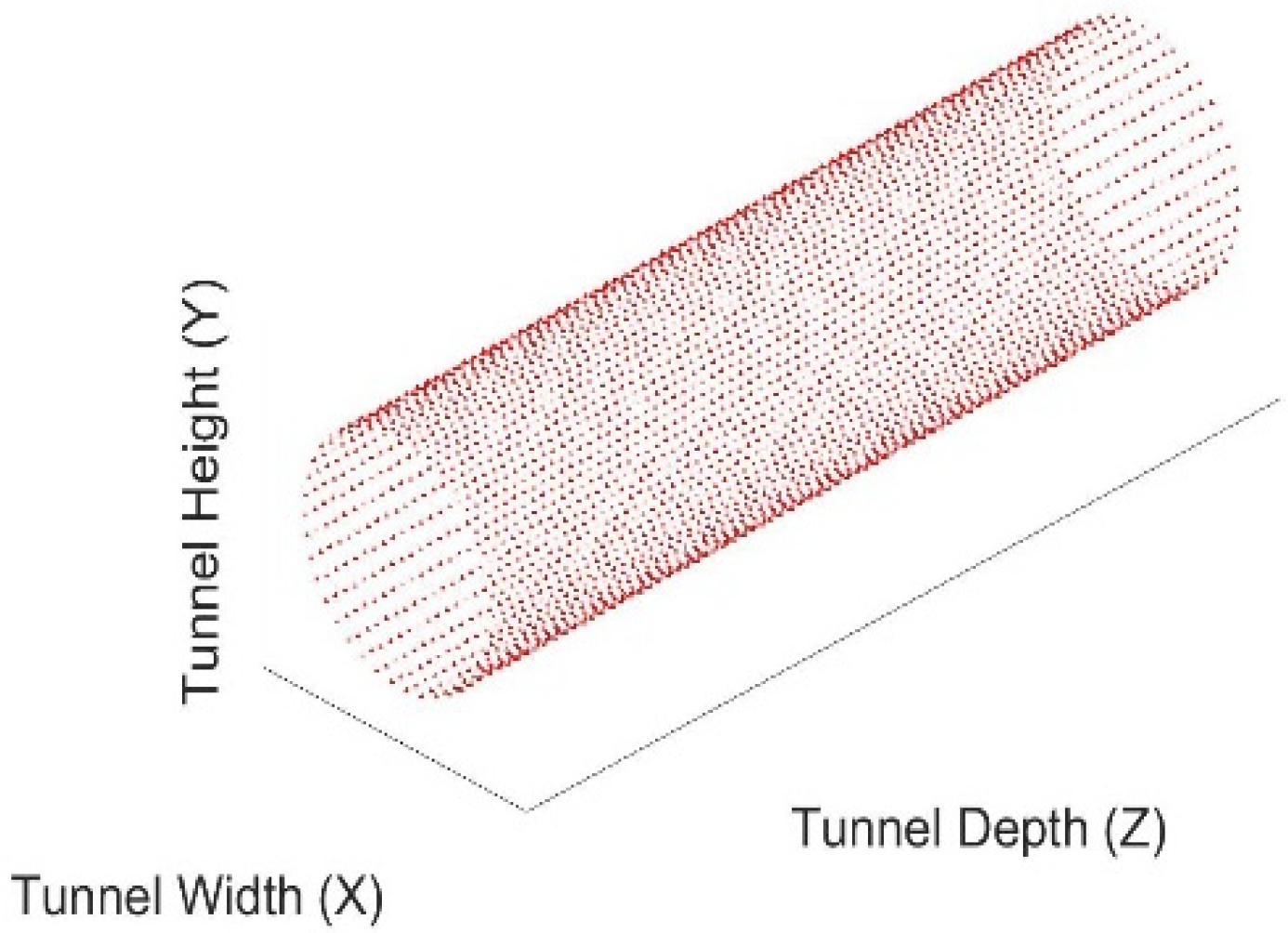
The plot in Figure 3 illustrates the full set of 40 fictitious forces representing the vibrational forces along the length of the tunnel. These forces are converted from line loads into point loads to be used in APDL. The PiP model outputs these forces, which simulate the tunnel’s vibration profile, and they are subsequently input into the FEA model to analyze ground-borne vibration propagation and its effects on nearby infrastructure.

3.2. Finite Element Analysis Using APDL

APDL is employed to perform FEA computations, which simulate how the vibrations propagate through the soil and interact with nearby building structures. The input source derived from the PiP model serves as the force input for the FE simulation, enabling a seamless transition between the tunnel’s vibration source and the detailed simulation of the surrounding environment. In the APDL environment, the soil medium is modeled using solid elements to represent different layers of soil, each characterized by its specific material properties.
The FE simulation incorporates the dynamic properties of the soil layers, which vary based on their material characteristics and interactions with the tunnel and structure. The model in Figure 4 shows the finite element mesh of the soil block used in the APDL environment, with SOLID185 elements representing the layers of soil. The element size is set to 0.5 throughout the soil model, with a finer mesh size of 0.25 around the tunnel to capture the complexities in this region. Boundary conditions are managed using perfectly matched layer (PML), they are defined by the SOLID185, SOLID186, and SOLID187 elements with KEYOPT (15) = 1. In a structural harmonic analysis, the outgoing elastic waves are absorbed by the PML without any reflections, and the fringing displacement is attenuated rapidly in the PML without affecting the values of displacement in the normal FEA domain. Thus, the use of PML leads to higher accuracy, especially in harmonic analysis.

3.3. Modeling a Building Within the PML Soil Model

A building is modeled as a 3D structure within the APDL environment and is fully coupled with the soil model. The building model includes foundation elements, floor slabs, walls, and key load-bearing components, ensuring that the vibrational effects are traced from the foundation level up to the higher stories of the structure. By incorporating dynamic properties of the building such as stiffness and damping, the model captures the building’s response to incoming vibrations from the soil, accounting for both horizontal and vertical transmission paths. The interaction between the soil and building is modeled using appropriate boundary conditions, with special attention to the foundation-soil interface. This ensures accurate transmission of vibrations from the tunnel, through the soil, and into the building structure. The model further accounts for the dynamic behavior of various structural components within the building, allowing for a thorough examination of how vibrations propagate from the foundation through the floors and walls.

4. Model Developments

4.1. Three-Dimensional Model

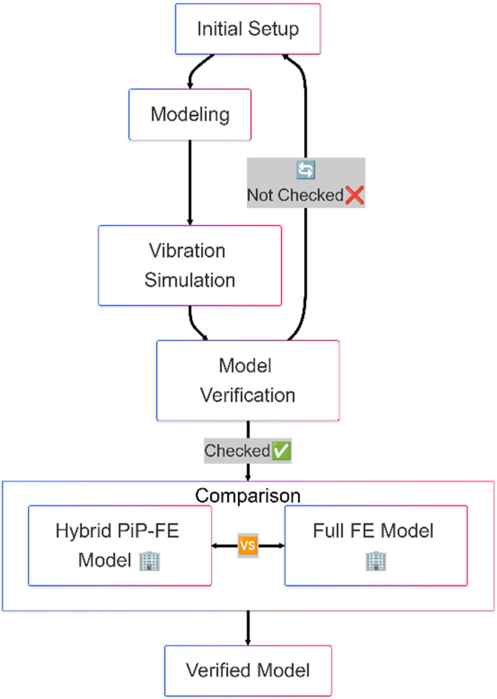
The flowchart in Figure 5 illustrates the process of building the numerical model to simulate ground-borne vibrations generated by metro tunnels and their transmission through soil to surrounding buildings. The process begins with defining the soil and tunnel parameters, followed by applying a transfer function to represent vibrational forces. Then it is subjected to convergence studies, which involve refining the mesh and adjusting parameters until the results become stable and independent of the mesh size, followed by verification studies to ensure the model’s accuracy. After completing the first stage verification, the model is either adjusted and refined or proceeds by applying the transfer function presenting the tunnel. These loads are modeled using the PiP model and then input into the FE model, which simulates the interaction between the tunnel and the surrounding soil to analyze vibrations in more detail. The next steps involve simulating vibration propagation through the soil and evaluating the vibration response at the surface. After the second stage verification, the final step is to predict the building’s structural response to the transmitted vibrations, completing the numerical modeling process. This workflow ensures thorough verification and refinement at multiple stages to improve the accuracy and reliability of the model.

4.2. Numerical Modeling

4.2.1. Description of the 3D Soil and Building Geometry

This study develops a comprehensive 3D model to simulate the transmission of ground-borne vibrations from metro tunnels through soil to an adjacent building, focusing on the interaction between the soil, tunnel, and building structure. The soil is modeled as a semi-infinite half-space with homogeneous and isotropic properties. A cylindrical metro tunnel, located below the ground surface, serves as the vibration source, with the tunnel-soil interaction simulated using the PiP model for efficient energy transfer. The building consists of a basement, ground floor, and three additional levels, supported by a shallow foundation. The structural response to the vibrations is captured using beam and plate elements. Perfectly matched layers in APDL are employed to infinite domain, preventing boundary reflections. The PiP model generates input forces through MATLAB, which are then imported into APDL for harmonic response analysis. Mesh generation is optimized to balance accuracy and computational efficiency, with higher mesh density around the tunnel and foundations. The soil is modeled as a homogeneous isotropic half-space to simplify the computational framework, and while this assumption is commonly adopted in vibration studies, it does not capture the effects of stratified or heterogeneous soil conditions, which can influence vibration propagation. The numerical parameters for the system are detailed in Table 1.

4.2.2. Modeling of a Building

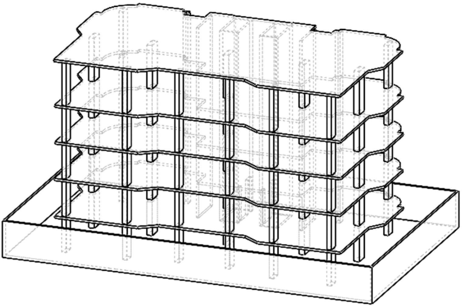
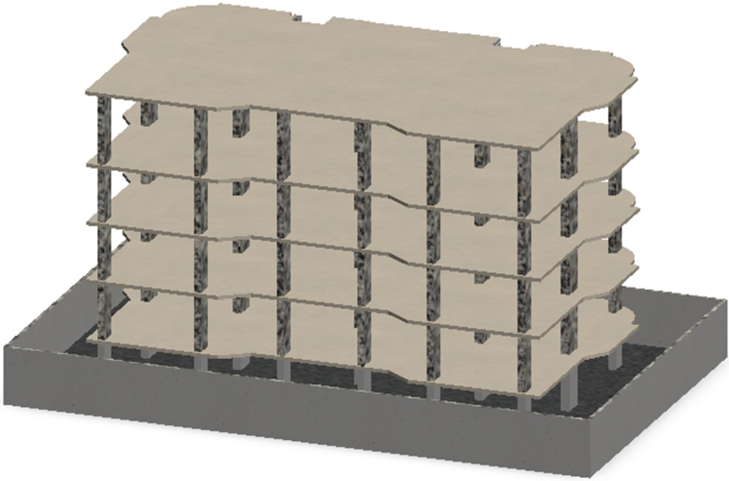
In this study, a real building located in Qatar was modeled using detailed dimensions and specifications obtained from official drawings provided by the owner (Figure 6 and Figure 7). The building, consisting of three floors, a ground floor, and a basement, is a representative structure commonly found in the region. The foundation was modeled as a raft foundation to reflect the actual construction practice, and the material properties of concrete and steel used in the building were based on local standards.

4.3. Model Convergence Studies

The validation of the 3D FEA model is a critical step to ensure its accuracy and reliability in simulating the transmission of ground-borne vibrations from metro tunnels. In this study, the FE model’s results are validated against the PiP model by comparing the vibration response at the surface due to a transfer function applied within the tunnel.

4.3.1. Model Size Convergence Study

In this study, model size refinement is crucial for assessing the influence of the soil model’s dimensions on vibration propagation, particularly in light of the use of PML at the boundaries of the soil model. The model size is defined by the overall length of the model in the x , y , a n d   z directions, representing the volume of the soil domain. As the use of PML mitigates the boundary effects at the outer edges of the model, the refinement of the inner boundary becomes a critical aspect in understanding its effect on vibration transmission through the soil. To quantify and evaluate this effect, Richardson Extrapolation is employed.
Richardson Extrapolation is a robust technique for improving the accuracy of numerical results by estimating the “true” solution based on results obtained from different mesh or boundary sizes [48]. This method leverages the assumption that the numerical error decreases predictably as the mesh becomes finer, allowing the estimation of the solution in the limit as the boundary size approaches infinity (or as mesh size approaches zero). Through this approach, the impact of inner boundary effects on the propagation of vibrations can be systematically assessed, providing a refined and accurate prediction of the vibration response in the soil model.
Numerical Development
Let S 1 and S 2 be the numerical solutions obtained using boundary sizes h 1 and h 2 respectively, where h 1 < h 2 and let p be the order of accuracy of the numerical method. The Richardson extrapolated solution S t r u e can be computed using the formula:
S t r u e = S 1 . h 2 p S 2 . h 1 p h 2 p h 1 p
where S 1 is the vibration response for boundary size h 1 , S 2 is the vibration response for boundary size h 2 , p is the order of the numerical method
  • Linear elements (straight lines for 1D, flat surfaces for 2D) are usually first order (i.e., p = 1 ).
  • Quadratic elements (second-degree polynomials for shape functions) are typically second-order (i.e., p = 2 ).
  • Cubic elements or higher-order shape functions would correspond to third-order or higher (i.e., p = 3 ).
Finite Element Analysis
The convergence test begins with a model boundary size of 25 × 25 × 25   m 3 , which is the minimum feasible size due to the load input being positioned 23 m from the surface. For computational and time efficiency, an element size of 1 m is used initially; however, the element size will be refined in later stages. The current analysis focuses on evaluating the convergence behavior using this element size. The results presented in this section correspond to a frequency of 150   H z and the parameters for the study are detailed in Table 2, with boundary size progressively refined until the convergence criterion is achieved, allowing for a detailed assessment of the inner boundary effects on the vibration response.
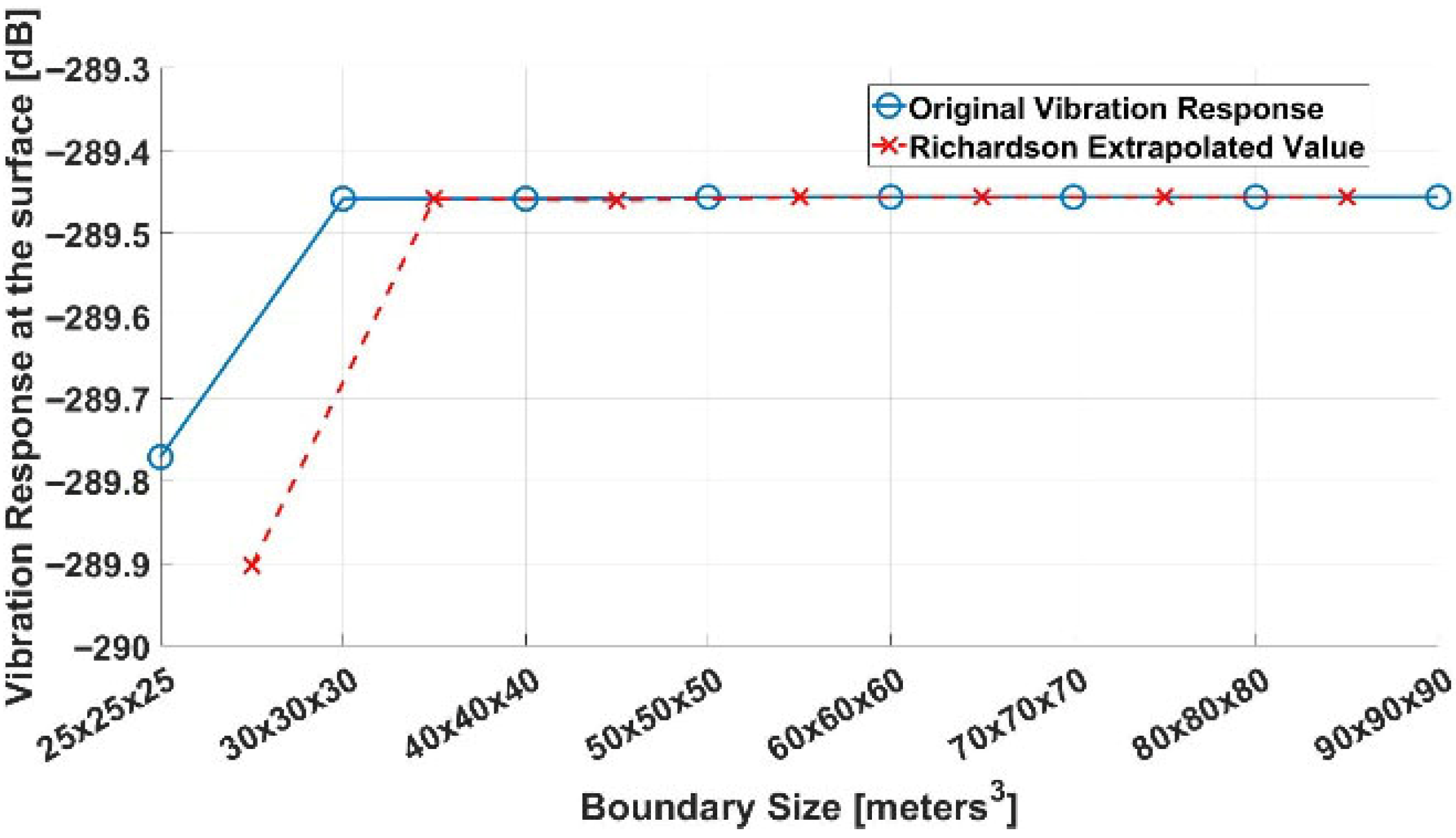
The plot in Figure 8 illustrates the convergence behavior of the vibration response at the surface as the boundary size of the soil model is refined, ranging from 25 × 25 × 25   m 3 , to 90 × 90 × 90   m 3 . The blue line with circles represents the original computed vibration response at each boundary size, while the red dashed line with crosses shows the Richardson extrapolated values. The initial boundary size of 25 × 25 × 25   m 3 , exhibits a significant change in vibration response, but as the boundary size increases, the results stabilize, converging around −289.45 dB. This convergence is further confirmed by the close agreement between the original and extrapolated values from a boundary size of 30 × 30 × 30   m 3 , onward, indicating that inner boundary effects diminish with larger boundary sizes.

4.3.2. Element Size Convergence Study

In this study, element size refinement is essential for assessing the influence of mesh resolution on vibration propagation within the soil model. The element size determines the level of discretization across the model’s volume, affecting the accuracy of the vibration response simulation. As smaller elements provide a more detailed representation of the physical domain, refining the element size becomes a critical step in evaluating how mesh resolution impacts vibration transmission through the soil. To assess convergence and the accuracy of the numerical results, a tolerance band is employed. The tolerance band represents an acceptable range around the target value, typically defined as a percentage deviation, such as ±1% or ±5%, from the converged result [49]. This approach allows for a clear graphical representation of whether the computed results are sufficiently close to the true solution as the element size is refined.
Nuermical Development
Let S c o m p u t e d represent the computed value of the vibration response at a given boundary size and let S c o n v e r g e d be the converged value of the response. The tolerance band can be defined using a percentage T of the converged value:
S l o w e r = S c o n v e r g e d · 1 T
S u p p e r = S c o n v e r g e d · ( 1 + T )
where
  • T is the tolerance percentage (e.g., 1% or 0.01).
  • S l o w e r   a n d   S u p p e r are the lower and upper bounds of the tolerance band.
The tolerance band helps visualize the stability of the numerical solution. If the computed results fall within this band for sufficiently small boundary sizes, the solution is considered converged. The narrowing of the tolerance band as the mesh refines is indicative of a solution approaching the true value.
Finite Element Analysis
The element size refinement study begins with an initial size of 1 m, decreasing by 0.1 m increments to assess mesh resolution effects on the vibration response. As the model size was refined in a previous study, the established convergence value based on the Pipe-in-Pipe model serves as a reliable benchmark. With only element size varying, the study focuses on ensuring the solution converges to the Pipe-in-Pipe value, optimizing analysis efficiency by concentrating solely on mesh refinement while maintaining the accuracy of the vibration response and the parameters for the study are detailed in Table 3.
The plot in Figure 9 shows the convergence behavior of the vibration response at the surface as the element size is progressively refined from 1 m to 0.3 m. An upper frequency of 150 Hz was selected as a practical balance between computational efficiency and physical relevance: while most ground-borne vibration energy lies below 80 Hz, building structural responses may extend into higher frequencies. Extending the band to 250 Hz produced negligible differences, confirming that 150 Hz sufficiently captures the dominant vibration content relevant to this study. The blue circles represent the computed vibration response values at various element sizes. The dashed red line indicates the converged value, derived from the PiP model, serving as the benchmark for this study. As the element size decreases, the vibration response converges toward this value, with a significant reduction in variation observed for element sizes below 0.6 m. Since the element size of 0.5 m enters the tolerance band, it is selected as the optimal element size. Further refining the element size below this value would require significantly higher computational resources, which is not efficient in terms of resources and time, making 0.5 m the most practical choice for this study.

4.4. Model Verification Studies

A vibration load is applied within the soil model in both the PiP and FE models to simulate the vibrations generated by the tunnel. The source is positioned at a depth of 20 m below the surface along the tunnel inverted in both models.

4.4.1. Transfer Function Application

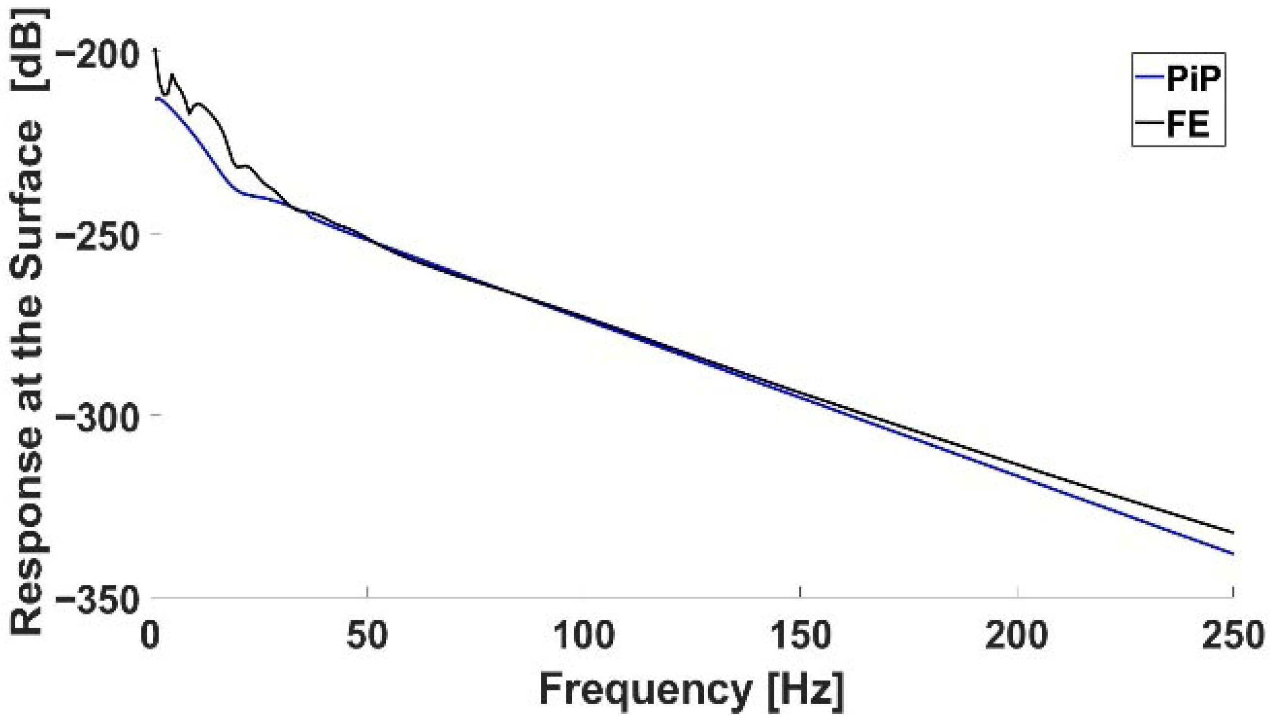
The plot in Figure 10 compares the surface vibration responses between the PiP model and the APDL FE model as a function of frequency based on the parameters detailed in Table 4. Both models exhibit a similar response pattern throughout the frequency range, with minor deviations at lower frequencies. The close agreement between the PiP and FE models demonstrates the ability of the FE model to accurately replicate the vibration behavior predicted by the PiP model.

4.4.2. Pipe in Pipe Tunnel Line Loads Application

The graph in Figure 11 illustrates the comparison of surface vibration responses as a function of frequency, using the parameters detailed in Table 5. This comparison is between the PiP model and the APDL FE model, with both scenarios representing the effect of the tunnel through 40 line loads. The responses show a consistent trend across the frequency spectrum, with the PiP and FE models closely aligning in their vibration behavior. Minor variations are observed at lower frequencies, but overall, the FE model effectively reproduces the PiP model’s predictions. This close correlation further validates the FE model’s accuracy in simulating surface vibration responses induced by tunnel dynamics.

5. Results and Comparisons

5.1. Fully Finite Element Model

The fully Finite Element (FE) model is a detailed computational model that simulates the dynamic behavior of the tunnel and surrounding soil in response to a transfer function, such as those generated by trains moving through a tunnel. The model discretizes the entire physical domain using finite elements, allowing for a comprehensive analysis of how vibrations propagate through the structure and into the surrounding soil. The fully FE model captures the intricate interactions between the tunnel and soil, accounting for the geometry, material properties, and boundary conditions. Due to its high fidelity and accuracy, the fully FE model is often used as the reference or benchmark in comparative studies to evaluate the performance of simplified or hybrid models, such as the PiP-FE model.

5.2. PiP-FE Model vs. Fully FE Model with Integrated Building

The vibration response at the surface is extracted from both the PiP-FE model and the fully FE model, focusing on the amplitude and frequency of vibrations at various points on the soil surface. For the fully FE model, a transfer function is applied directly to simulate the dynamic behavior of the tunnel. In the hybrid PiP-FE model, the effect of the tunnel is replicated using 40 fictitious forces derived from the PiP. By comparing the results, the assessment of the PiP-FE model’s ability to accurately replicate the vibrational behavior predicted by the fully FE model is facilitated. This comparison also evaluates the computational efficiency of the PiP-FE model while ensuring it captures the essential dynamic characteristics of the system.
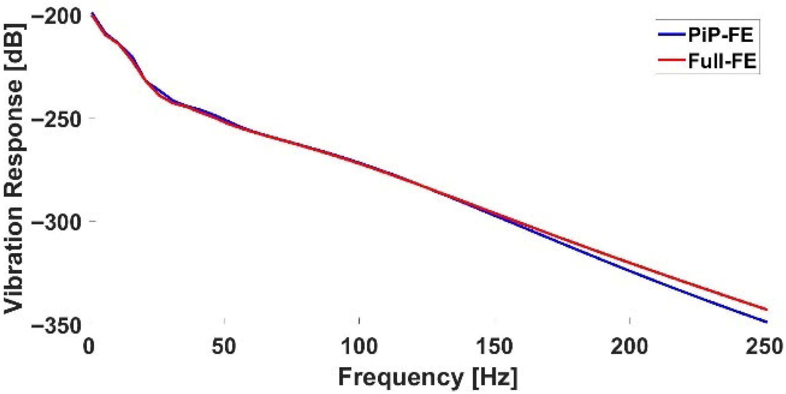
The graph in Figure 12 shows the comparison of the vibration response at the surface as a function of frequency between the Hybrid (PiP-FE) model and the fully Finite Element model, using the parameters detailed in Table 6. Both models simulate the vibration response due to a transfer function applied within the tunnel. The results indicate that the PiP-FE and fully FE models exhibit similar trends across the frequency spectrum, with both models showing close agreement, particularly at lower-to-mid frequencies. At higher frequencies, there is a small deviation between the two models, but overall, the PiP-FE model effectively approximates the fully FE model’s vibration behavior, particularly in the low-to-mid frequency range.
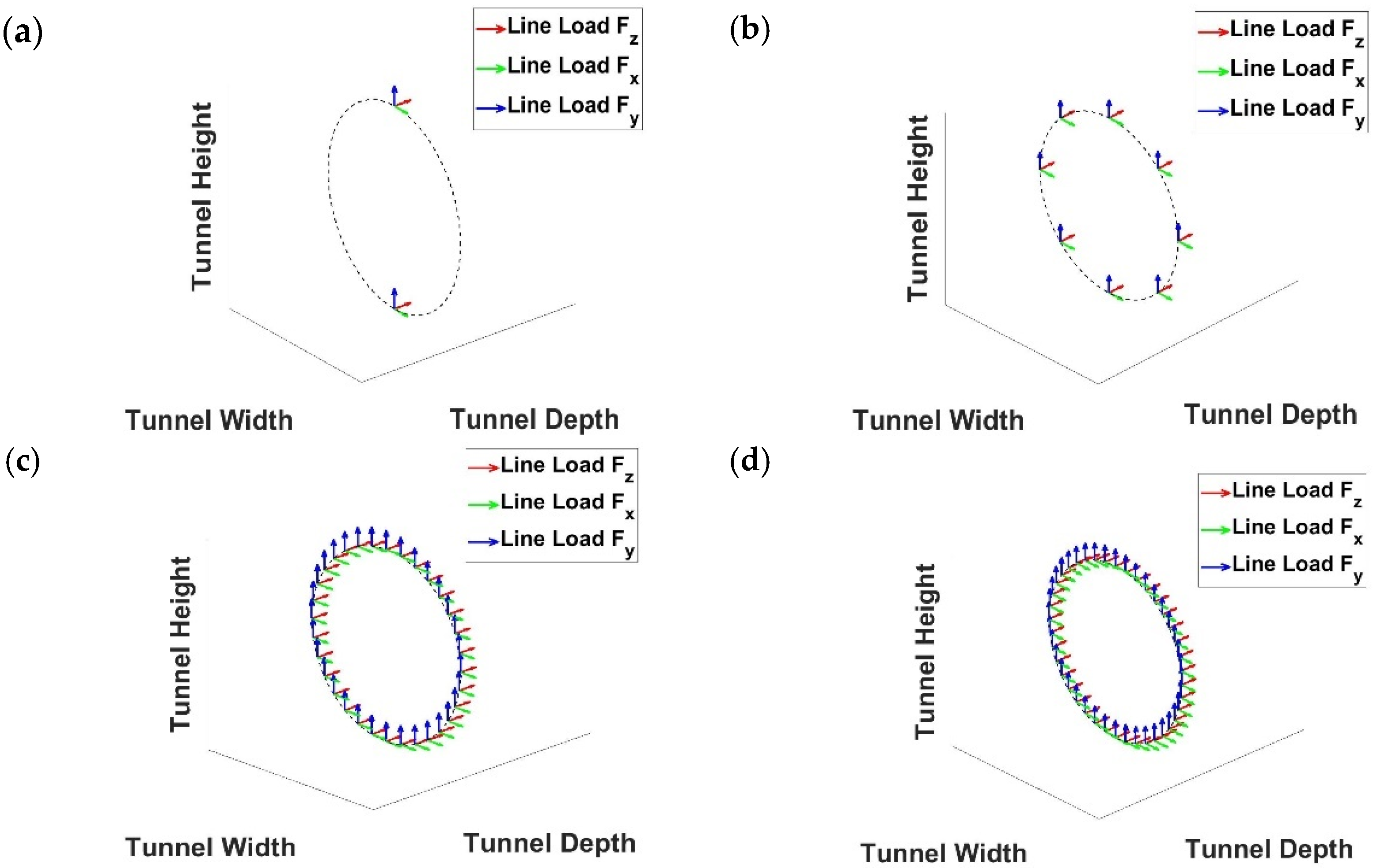
The plots in Figure 13 show various configurations of line loads applied along the circumference of a tunnel in three directions: F x (tunnel width), F y (tunnel depth), and F z (tunnel height). In Figure 13a–d, the loads are represented as vectors, depicting the orientation and magnitude of forces at different points around the tunnel’s cross-section, with increasing load density from (a) to (d). This figure compares the effects of varying the number of load points on the tunnel’s perimeter in structural or vibrational simulations.
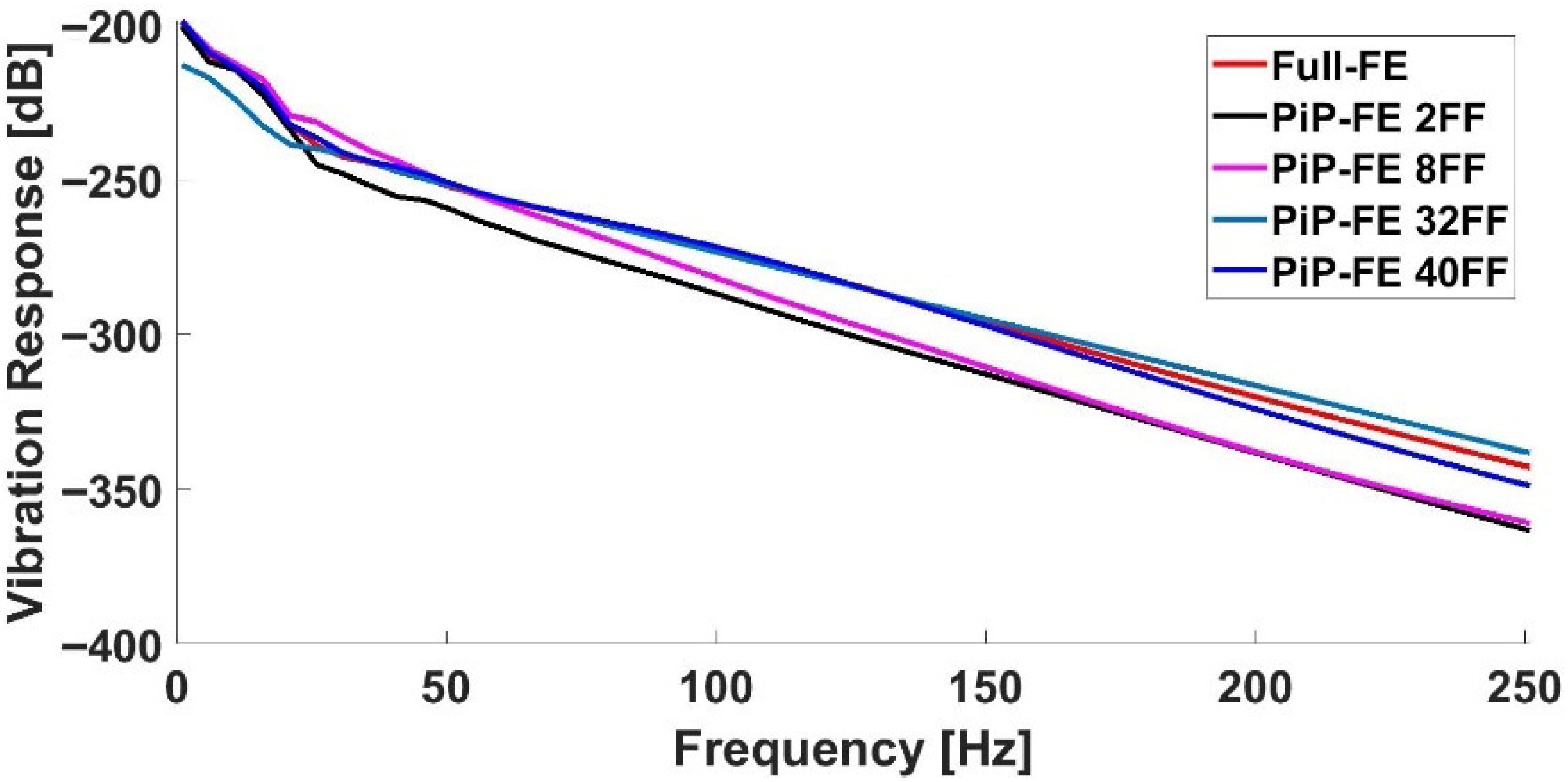
The graph in Figure 14 compares the surface vibration response between the PiP-FE model and the full FE model using different numbers of fictitious forces (2, 8, 32, and 40) over a frequency range of 0–250 Hz. As the number of fictitious forces increases, the PiP-FE model’s response converges toward that of the full FE model, with the 40 fictitious forces configuration showing the closest match to the full model’s results.

5.3. Error Analysis of PiP-FE and Full FE Models Across Frequency Spectrum

This section presents the RMS error and percentage error between the PiP-FE model and the full FE model, highlighting the impact of increasing the number of fictitious forces on model accuracy across the frequency range.

5.3.1. Percentage Error

P e r c e n t a g e   E r r o r = S F E f S F E P i P ( f ) S F E P i P ( f i ) × 100
where S F E P i P ( f ) & S F E ( f ) are the responses at specific frequency f .
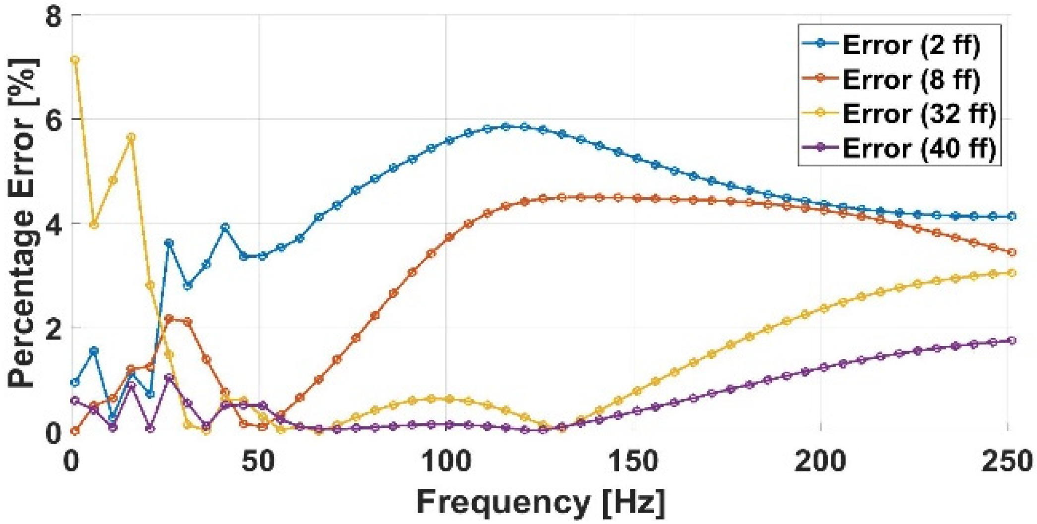
The graph in Figure 15 presents the percentage error in vibration response between the PiP-FE and Full FE models for different numbers of fictitious forces (2, 8, 32, and 40). As expected, the error decreases significantly as the number of fictitious forces increases, reflecting a more accurate representation of the tunnel load distribution. For the lowest cases (2 and 8 forces), the error remains relatively high, indicating that the simplified loading fails to capture the tunnel’s dynamic effect. With 32 forces, the error is substantially reduced, and at 40 forces the maximum resolution permitted by the PiP formulation the percentage error falls consistently below 1%. This confirms that using the full set of 40 fictitious forces provides an optimal balance, achieving close agreement with the Full FE model while ensuring computational efficiency.

5.3.2. Root Mean Square (RMS) Error

R M S   E r r o r = 1 n i = 1 n S F E ( f i ) S F E P i P ( f i ) 2
where S F E P i P ( f i ) & S F E ( f i ) are the responses at frequency f i , and n is the total number of frequency points.
The bar graph in Figure 16 shows the RMS error in dB for the fully FE model with varying numbers of fictitious forces (2, 8, 32, and 40) compared to the hybrid PiP-FE model. As the number of fictitious forces increases, the error decreases, with 40 forces achieving the lowest RMS error of 2.74 dB. The PiP model permits a maximum of 40 fictitious forces to represent the tunnel’s effect, corresponding to the full resolution of the load distribution along the tunnel circumference. Using fewer forces (2, 8, or 32) provides approximate representations, which reduces computational cost but introduces larger errors. As expected, accuracy improves as the number of forces increases, with the 40-force case achieving less than 1% deviation from the fully detailed FE model. While 40 represents the theoretical maximum in the PiP formulation, it also reflects a practical trade-off between accuracy and computational demand, since lower-force cases require less power but yield noticeably higher deviations. This demonstrates the PiP-FE model’s accuracy and confirms that using the full number of fictitious forces provides the most accurate modeling of the tunnel’s effect.

5.4. Evaluation of Vibration Transmission in Building Floors

In this section, the evaluation of the vibration transmission behavior across the building floors is conducted by comparing the results of the Full Finite Element (FE) model with those of the Hybrid FE-PiP model. The comparison focuses on the vibration response at different floor levels due to a transfer function applied within the tunnel. By analyzing the vibration levels across the building’s floors (from the basement to the top floors), the accuracy and efficiency of the Hybrid FE-PiP model in replicating the dynamic behavior of the fully detailed FE model are assessed. This analysis highlights the effectiveness of using fictitious forces in the PiP model to represent the tunnel’s influence.
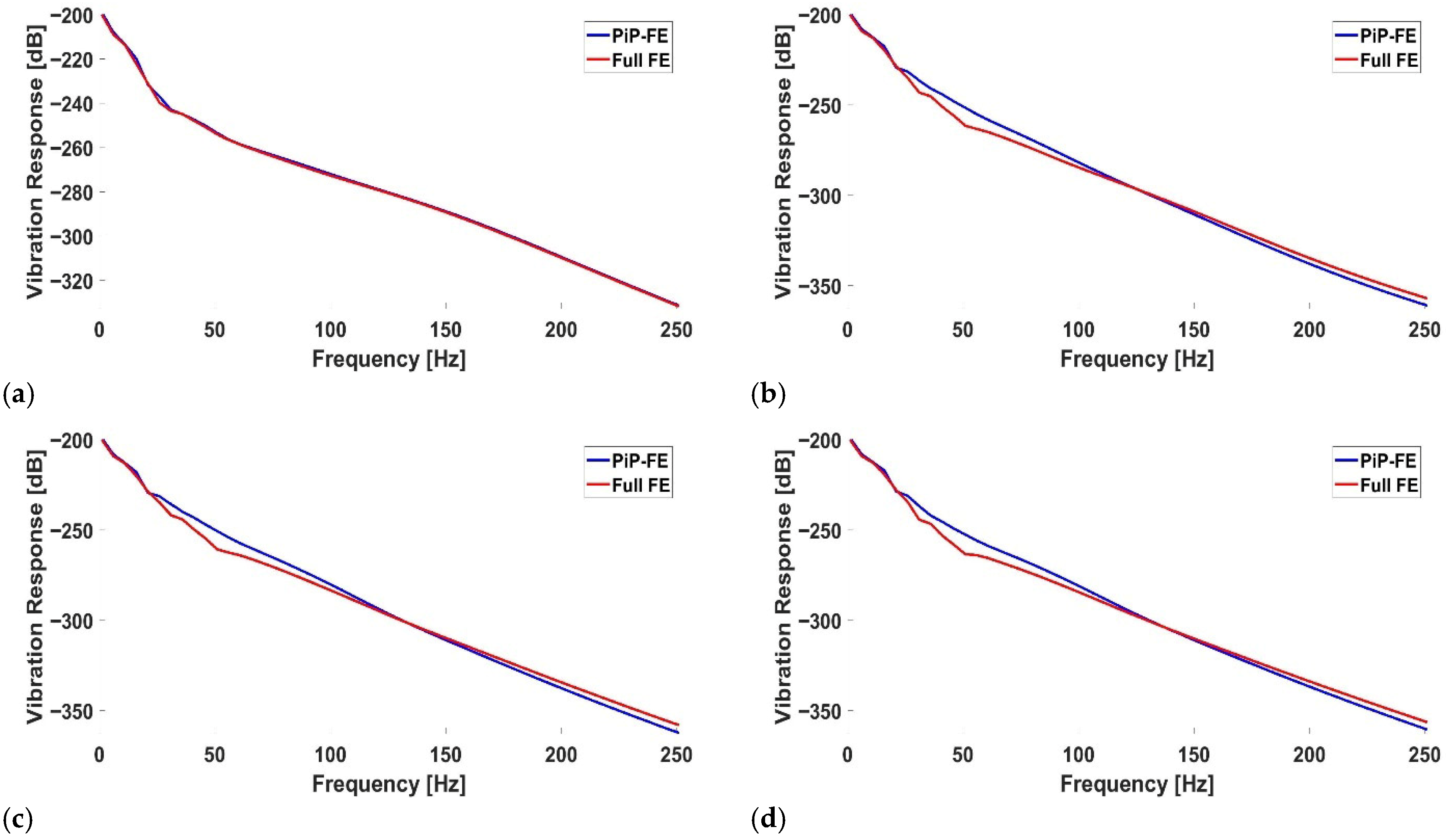
The plots in Figure 17, show the vibration responses between the Full FE and Hybrid FE-PiP models at four different floor levels: (a) Basement, (b) First Floor, (c) Second Floor, and (d) Third Floor. The graphs demonstrate the close agreement between the two models, indicating the Hybrid FE-PiP model’s reliability in replicating the Full FE model’s results.
Figure 18 presents the vibration response distributions across all building floors for both the PiP-FE model and the Full FE model. The values are normalized in decibels (dB) relative to the ground floor, which is taken as the 0.00 dB reference. Both models exhibit similar patterns across the basement, ground floor, and upper levels, confirming that the hybrid PiP-FE approach accurately reproduces the Full FE model’s predictions. The results also illustrate the vertical transmission of vibrations within the building, where relative response levels vary with height, emphasizing the importance of capturing floor-by-floor dynamics. The close agreement between the two models validates the robustness of the PiP-FE method for predicting structural vibration behavior.

5.5. Evaluation of PiP Model Accuracy at Minimal Tunnel Depth

In this segment of the study, the accuracy of the Pipe-in-Pipe (PiP) model under conditions where the tunnel is positioned as close as possible to the foundation raft, specifically within one diameter above the tunnel-a scenario that tests the critical boundary of the model’s assumptions is investigated. This approach was designed to determine the reliability of the PiP model in simulating the vibrations and structural impacts when the tunnel is near the critical zone, which is often a realistic concern in environments that are close to underground tunnel systems. By strategically positioning the tunnel in close proximity to the building’s raft foundation, the study aims to capture the most intense interactions and assess whether the PiP model maintains its predictive accuracy under such constrained conditions.
The results in Figure 19 demonstrate that even when the tunnel is placed at the maximum allowable distance of 6 m from the raft foundation, the vibration response predictions from the Hybrid PiP-FE model closely match those from the Full FE model across all floors (basement to third floor) and throughout the frequency range. This consistency highlights that, despite the PiP model’s simplifying assumptions, it remains highly accurate in simulating vibration behavior even under challenging conditions. The minimal deviation between the two models (less than 1%) validates the reliability of the Hybrid PiP-FE model, confirming its ability to produce precise results.

5.6. Computational Performance Analysis

The simulations were conducted on a Dell Precision 7760 workstation (Dell Inc., Round Rock, TX, USA) with the following configuration: Intel Xeon W-11955M CPU (Intel Corporation, Santa Clara, CA, USA) at 2.60 GHz, 128 GB RAM, and dual GPUs NVIDIA RTX A5000 Laptop GPU (NVIDIA Corporation, Santa Clara, CA, USA) with 16 GB VRAM and Intel UHD Graphics. MATLAB 2021b (MathWorks, Natick, MA, USA) and ANSYS Research Academic Version 2021 R2 (ANSYS Inc., Canonsburg, PA, USA) were used to run the simulations. The computational performance comparison was carried out at 150 Hz as a representative frequency. Since the efficiency gains result primarily from the reduced system size and degrees of freedom in the PiP-FE model, the improvements are expected to hold across the frequency spectrum, although low-frequency ranges (1–80 Hz), which are critical for metro-induced vibrations, will be explicitly investigated in future work. The table below shows the computational requirements, total simulation time, and RMS error for different model configurations:
The Full-FE and PiP-FE models utilize distinct computational frameworks for vibration analysis, leading to notable differences in computational demands. Specifically, as derived from the data in Table 7, the findings suggest that the Full-FE model consumes approximately 65% more resources, requiring 883 s of elapsed time and 51,747 MB of memory, compared to 536 s and 31,329 MB for the PiP-FE model, with respective CPU times of 672.6 and 410.5 s. These variances stem largely from the models’ handling of the tunnel geometry: both models start with the same volume of 30 × 30 × 30 m3 and initially similar element sizes. However, the curved geometry of the tunnel necessitates a finer mesh around the tunnel area in both models, reducing the element size to 0.25 m to accurately capture the geometry and ensure proper node placement for the 40FF. This refinement is crucial for achieving proper convergence around the tunnel’s circular shape, applied consistently in both models to maintain the same modeling parameters. Such differences in element management contribute significantly to the overall computational load, with the Full-FE model’s detailed simulation of the entire system increasing its complexity, whereas the PiP-FE model benefits from the Pipe-in-Pipe approximation that simplifies the problem and reduces the number of degrees of freedom.

6. Discussion

6.1. Consistency Between PiP-FE and Full-FE Predictions

The PiP-FE model reproduced the baseline Full-FE predictions with high accuracy when the full set of 40 fictitious forces was applied. Across the studied frequency range, the hybrid model tracked amplitude-frequency variation, phase response, and building floor-level outputs with deviations consistently below 1%. This confirms that the fictitious-force formulation adequately represents the tunnel-soil interaction for engineering-level predictions. Minor discrepancies at higher frequencies reflect sensitivity to scattering and local resonances but remain within acceptable engineering tolerance.

6.2. Parameter Convergence and Modeling Choices

6.2.1. Element Size

The mesh sensitivity analysis showed monotonic convergence with element refinement. A soil element size of 0.5 m achieved accuracy within the target tolerance, while finer discretization produced negligible improvements relative to the significant increase in computational cost. This validates 0.5 m as an optimal resolution.

6.2.2. Number of Fictitious Forces

Increasing fictitious forces improved accuracy progressively. With 40 forces, the PiP-FE solution differed from the Full-FE baseline by less than 1%, while the computational demand remained manageable. For the full set of fictitious forces, the error was minimal, confirming 40 as the optimal choice.

6.3. Frequency-Domain Behavior and Band Selection

An upper frequency of 150 Hz was adopted to size the mesh and benchmark efficiency. This aligns with the common observation that most ground-borne vibration energy is concentrated below ~80 Hz, whereas building responses can exhibit higher-frequency content due to local modes and floor systems. Extending the analysis band to 250 Hz produced negligible differences in the key output measures used here, confirming that 150 Hz captures the dominant content relevant to the present case. This is consistent with published trends where long-wavelength components govern transmission to the free field and into low-to-mid-rise buildings, with high-frequency content attenuating rapidly with distance and soil damping. As a limitation, the computational savings were quantified at 150 Hz; extending the efficiency audit to 1–80 Hz (the band most frequently emphasized in metro-induced vibration guidelines) is identified as future work.

6.4. Building Response Characteristics

For the shallow-foundation building, the PiP-FE model reproduced floor-level amplification and attenuation patterns observed in the Full-FE model. Peaks in amplification occurred near soil-structure resonance frequencies, while attenuation occurred outside resonance bands. The agreement between the two models indicates that the PiP-derived interface loading provides a reliable substitute for explicitly modeling the tunnel zone, while still capturing structural dynamics of the building domain.

6.5. Computational Efficiency and Scalability

Quantitatively, the Full-FE model required ~65% more elapsed time and ~65% more memory than the hybrid PiP-FE model (883 s vs. 536 s total elapsed time reported). CPU utilization favored the Full-FE model only in raw parallel workload but did not offset the overall wall-clock difference. These results align with general experience that replacing the near-source discretization by an equivalent fictitious-force boundary loading reduces the number of DOFs and the cost of factorization/iterations without losing accuracy at the building readings. The demonstrated results enable parametric studies (e.g., varying soil stiffness, embedment, or structural configurations) that would otherwise be impractical with a full 3D tunnel-to-building mesh.

6.6. Practical Implications

The PiP-FE framework demonstrates a reliable and efficient tool for ground-borne vibration assessments. It provides a systematic approach where element size and fictitious-force count can be pre-calibrated with simple convergence checks. The demonstrated accuracy and reduced cost make the framework suitable for design-stage evaluations and sensitivity studies.

6.7. Limitations and Directions for Further Work

The present work assumes a homogeneous, isotropic soil half-space and shallow foundations. Soil layering, heterogeneity, and deep foundations could alter transmission behavior and resonance characteristics. Additionally, validation was limited to model-to-model comparison; extending validation with field data would strengthen reliability. Future studies should also extend the efficiency analysis to the 1–80 Hz range, which is most relevant for vibration comfort and building serviceability assessments.

7. Conclusions

This study introduces a novel integration of the Pipe-in-Pipe (PiP) model with Finite Element Analysis (FEA) in Ansys Parametric Design Language (APDL) to simulate ground-borne vibrations generated by metro tunnels and their transmission to multi-story buildings. For the first time, a detailed 3D building model has been incorporated into the PiP framework, enabling a comprehensive assessment of how vibrations propagate from the tunnel through the soil and into various structural components of a building. The hybrid PiP-FE model was rigorously validated through a two-step process. First, the PiP model was verified by comparing it with a fully detailed FE model in APDL for simulating vibration propagation through soil. The results demonstrated close agreement between the PiP and FEA models across the frequency range of 1–250 Hz, confirming that the PiP model can accurately capture soil-tunnel interactions with computational efficiency.
Next, the hybrid PiP-FE model was extended to include the 3D building model, which was verified against a conventional full FE model of the building. By utilizing the maximum 40 fictitious forces to represent the tunnel’s effect, the PiP-FE model achieved less than 1% deviation from the fully detailed FE model, while smaller numbers of forces introduced larger errors. The choice of 40 fictitious forces reflects a trade-off, providing high accuracy within 1% while keeping computational time and memory requirements within practical limits. Furthermore, the hybrid model accurately predicted vibration responses at various building floors while significantly reducing computational effort. Specifically, the Full-FE model required 883 s and ~51 GB memory, compared to 536 s and ~31 GB for the PiP-FE model, representing savings of approximately 40% in runtime and 65% in memory usage. This contrast highlights the PiP-FE model’s ability to preserve accuracy while delivering significant computational efficiency. However, as the computational performance comparison was conducted at 150 Hz, future work will extend this analysis to lower frequencies (1–80 Hz), which are particularly relevant for metro-induced ground-borne vibrations.
Moreover, even when the tunnel was moved to its maximum allowable vertical distance between top of tunnel and bottom of foundation of 6 m, the PiP-FE model continued to closely match the Full-FE model’s results, with less than 1% deviation observed. This further confirms the PiP-FE model’s robustness and accuracy in capturing critical interactions, even under challenging conditions. These findings make the PiP-FE model a practical and scalable solution for complex ground-borne vibration analysis, especially in scenarios where detailed simulations are required without excessive computational burden. The research provides a robust framework for ground-borne vibration systems and their extension to buildings, addressing the limitations of traditional PiP models by enabling the integration of complex building structures. While this study has focused on a representative multi-story building case, the methodology demonstrates potential for extension to other models and scenarios, offering a promising approach for future applications where integrating different numerical methods can enhance efficiency and accuracy. Nevertheless, the present validation has been limited to numerical comparisons, and future work will incorporate field measurement data to further strengthen the framework’s applicability under real metro-induced vibration conditions; also, future extensions of this framework will consider layered and heterogeneous soil conditions to further improve applicability to complex geological scenarios.

Author Contributions

Conceptualization, O.A. and M.H.; methodology, O.A. and M.H.; software, O.A.; validation, O.A.; formal analysis, O.A.; investigation, O.A., M.H. and J.R.; resources, J.R.; data curation, O.A.; writing—original draft preparation, O.A.; writing—review and editing, O.A., M.H. and J.R.; visualization, O.A.; supervision, M.H. and J.R.; project administration, M.H. and J.R.; funding acquisition, M.H. and J.R. All authors have read and agreed to the published version of the manuscript.

Funding

This research was funded by Qatar Rail through grant number QUEX-QatarRail-22/23-4.

Data Availability Statement

All key model parameters and numerical inputs are fully reported within the article to ensure reproducibility. The dataset generated and analyzed during the current study (Data.xlsx) is openly available at GitHub: https://github.com/omran2120/Data/blob/79341d751c73bcdc75af51c681f249add06580f9/Data.xlsx, accessed on 10 September 2025.

Acknowledgments

The authors would like to thank Qatar Rail for their support.

Conflicts of Interest

The authors declare no conflict of interest.

References

  1. Hao, Y.; Qi, H.; Liu, S.; Nian, V.; Zhang, Z. Study of noise and vibration impacts to buildings due to urban rail transit and mitigation measures. Sustainability 2022, 14, 3119. [Google Scholar] [CrossRef]
  2. Lopes, P.; Alves Costa, P.; Ferraz, M.; Calçada, R.; Silva Cardoso, A. Numerical modeling of vibrations induced by railway traffic in tunnels: From the source to the nearby buildings. Soil Dyn. Earthq. Eng. 2014, 61–62, 269–285. [Google Scholar] [CrossRef]
  3. Hussein, M.F.M.; Hunt, H.E.M. A numerical model for calculating vibration from a railway tunnel embedded in a full-space. J. Sound Vib. 2007, 305, 401–431. [Google Scholar] [CrossRef]
  4. Hussein, M.F.M.; Francois, S.; Schevenels, M.; Hunt, H.E.M.; Talbot, J.P.; Degrande, G. The fictitious force method for efficient calculation of vibration from a tunnel embedded in a multi-layered half-space. J. Sound Vib. 2014, 333, 6996–7018. [Google Scholar] [CrossRef]
  5. Zhang, X.; Zhou, S.; He, C.; Di, H.; Si, J. Experimental investigation on train-induced vibration of the ground railway embankment and under-crossing subway tunnels. Transp. Geotech. 2021, 26, 100422. [Google Scholar] [CrossRef]
  6. Chen, X.; Liao, W.; Tang, Z.; Wu, J. Field test and numerical study of train-induced vibration of over-track buildings above metro depot. Urban Rail Transit 2022, 8, 1–12. [Google Scholar] [CrossRef]
  7. Qu, S.; Yang, J.; Zhu, S.; Zhai, W.; Kouroussis, G.; Zhang, Q. Experimental study on ground vibration induced by double-line subway trains and road traffic. Transp. Geotech. 2021, 29, 100564. [Google Scholar] [CrossRef]
  8. Forrest, J.A.; Hunt, H.E.M. Ground vibration generated by trains in underground tunnels. J. Sound Vib. 2006, 294, 706–736. [Google Scholar] [CrossRef]
  9. Yuan, Z.; Boström, A.; Cai, Y. Benchmark solution for vibrations from a moving point source in a tunnel embedded in a half-space. J. Sound Vib. 2017, 387, 177–193. [Google Scholar] [CrossRef]
  10. He, C.; Zhou, S.; Di, H.; Guo, P.; Xiao, J. Analytical method for calculation of ground vibration from a tunnel embedded in a multi-layered half-space. Comput. Geotech. 2018, 99, 149–164. [Google Scholar] [CrossRef]
  11. Cao, Z.; Bai, X.; Yuan, Z.; Wang, J.; Zheng, K.; Xu, Y. An analytical solution for the dynamic tunnel-soil-shallow foundation interaction under a harmonic point load. Soil Dyn. Earthq. Eng. 2023, 164, 107647. [Google Scholar]
  12. Di, H.; Zhou, S.; Guo, H.; He, C.; Zhang, X. Three-dimensional analytical model for vibrations from a tunnel embedded in an unsaturated half-space. Acta Mech. 2021, 232, 1543–1562. [Google Scholar] [CrossRef]
  13. Song, W.; Zou, D.; Liu, T.; Zhou, A. Dynamic response of unsaturated full-space caused by a circular tunnel subjected to a vertical harmonic point load. Soil Dyn. Earthq. Eng. 2020, 130, 106005. [Google Scholar] [CrossRef]
  14. Yuan, Z.; Cao, Z.; Cai, Y.; Geng, X.; Wang, X. An analytical solution to investigate the dynamic impact of a moving surface load on a shallowly-buried tunnel. Soil Dyn. Earthq. Eng. 2019, 126, 105816. [Google Scholar] [CrossRef]
  15. Jin, Q. Investigation of ground vibration from circular tunnels using a fictitious-force-based method. In Proceedings of the Stephenson Conference: Research for Railways, London, UK, 21–23 April 2015. [Google Scholar]
  16. Zhou, S. An efficient method for predicting train-induced vibrations from a tunnel in a poroelastic half-space. Eng. Anal. Bound. Elem. 2017, 85, 43–56. [Google Scholar] [CrossRef]
  17. Connolly, D.P.; Kouroussis, G.; Laghrouche, O.; Ho, C.L.; Forde, M.C. Benchmarking Railway Vibrations—Track, Vehicle, Ground and Building Effects. Constr. Build. Mater. 2015, 92, 64–81. [Google Scholar] [CrossRef]
  18. Yuan, Z.; Li, C.Y.; Ma, L.X.; Liu, W.F.; Cai, Y. Periodic FE–BE Modelling of Vibration from Twin Tunnels Incorporating Fictitious-Force Concepts. Eur. J. Environ. Civ. Eng. 2024. advance online publication. [Google Scholar]
  19. Colaço, A.; Barbosa, D.; Costa, P.A. Hybrid soil-structure interaction approach for the assessment of vibrations in buildings due to railway traffic. Transp. Geotech. 2022, 32, 100691. [Google Scholar] [CrossRef]
  20. Andersen, L.; Jones, C.J.C. Coupled boundary and finite element analysis of vibration from railway tunnels-A comparison of two- and three-dimensional models. J. Sound Vib. 2006, 293, 611–625. [Google Scholar] [CrossRef]
  21. Sheng, X.; Jones, C.J.C.; Thompson, D.J. Prediction of ground vibration from trains using the wavenumber finite and boundary element methods. J. Sound Vib. 2006, 293, 575–586. [Google Scholar] [CrossRef]
  22. Yang, W.; Hussein, M.F.M.; Marshall, A. Centrifuge and numerical modelling of ground-borne vibration from an underground tunnel. Soil Dyn. Earthq. Eng. 2013, 51, 23–34. [Google Scholar] [CrossRef]
  23. Yang, W.; Hussein, M.F.M.; Marshall, A.; Cox, C. Centrifuge and numerical modelling of ground-borne vibration from surface sources. Soil Dyn. Earthq. Eng. 2013, 44, 78–89. [Google Scholar] [CrossRef]
  24. Tu, W.; Shen, L.; Zhang, P.; Zhang, X.; Liu, L.; Chen, J. A hybrid methodology for the prediction of subway train-induced building vibrations based on the ground surface response. Transp. Geotech. 2024, 48, 101330. [Google Scholar] [CrossRef]
  25. He, C.; Zhou, S.; Di, H.; Zhang, X. An efficient prediction model for vibrations induced by underground railway traffic and experimental validation. Transp. Geotech. 2021, 31, 100646. [Google Scholar] [CrossRef]
  26. Parry, G.; Summers, S.; Yates, D. Validation of the Pipe-in-Pipe vibration software model for ground-borne noise and vibration predictions above construction tunnels. Int. J. Rail Transp. 2015, 3, 249–260. [Google Scholar] [CrossRef]
  27. Noori, B.; Arcos, R.; Clot, J.; Romeu, J. A computationally efficient model for calculating 2.5D Green’s functions in layered half-space systems. In Proceedings of the 24th International Congress on Sound and Vibration (ICSV24), London, UK, 23–27 July 2017. [Google Scholar]
  28. Kuo, K.A.; Hussein, M.F.M.; Hunt, H.E.M. Developments of the PiP model for tunnel-soil interaction analysis. In Dynamics of Coupled Structures; Springer: Berlin/Heidelberg, Germany, 2015; Volume 4, pp. 53–61. [Google Scholar] [CrossRef]
  29. O’Brien, J.; Rizos, D.C. A 3D FEM-BEM methodology for simulation of high-speed train induced vibrations. Soil Dyn. Earthq. Eng. 2005, 25, 289–301. [Google Scholar] [CrossRef]
  30. Takemiya, H.; Bian, X.C. Substructure simulation of inhomogeneous track and layered ground dynamic interaction under train passage. J. Eng. Mech. 2005, 131, 699–711. [Google Scholar] [CrossRef]
  31. Gupta, S.; Hussein, M.; Degrande, G.; Hunt, H.; Clouteau, D. A comparison of two numerical models for the prediction of vibrations from underground railway traffic. Soil Dyn. Earthq. Eng. 2007, 27, 608–624. [Google Scholar] [CrossRef]
  32. Qu, S.; Yang, J.; Zhu, S.; Zhai, W.; Kouroussis, G. A hybrid methodology for predicting train-induced vibration on sensitive equipment in far-field buildings. J. Sound Vib. 2021, 491, 115754. [Google Scholar] [CrossRef]
  33. Alsharo, A.; Douier, K.; Hussein, M.F.M.; Renno, J. Investigating the effect of using softer rail-pads on ground-borne vibration from underground railways. Int. J. Rail Transp. 2023, 12, 803–826. [Google Scholar] [CrossRef]
  34. Khan, M.R.; Dasaka, S.M. Quantification of ground-vibrations generated by high speed trains in ballasted railway tracks. Transp. Geotech. 2019, 20, 100245. [Google Scholar] [CrossRef]
  35. Jones, S.; Kuo, K.A.; Hussein, M.F.M.; Hunt, H.E.M. Prediction uncertainties and inaccuracies resulting from common assumptions in modelling vibration from underground railways. J. Rail Rapid Transp. 2012, 226, 501–512. [Google Scholar] [CrossRef]
  36. Hunt, H.E.M.; Hussein, M.F.M. Vibration from railways: Can we achieve better than +/−10dB prediction accuracy? In Proceedings of the 14th International Congress on Sound and Vibration, Cairns, Australia, 9–12 July 2007.
  37. Hua, A.; Li, Y.; Deng, Y.; Xie, K. Vibration of layered saturated ground with a tunnel subjected to an underground moving load. Comput. Geotech. 2020, 119, 103342. [Google Scholar] [CrossRef]
  38. Zhou, S.; He, C.; Guo, P.; Di, H.; Xiao, J. Three-Dimensional Analytical Model for Coupled Track-Tunnel-Soil System in a Multilayered Half-Space. J. Eng. Mech. 2020, 146, 04019121. [Google Scholar] [CrossRef]
  39. He, C.; Zhou, S.; Guo, P.; Di, H.; Zhang, X. Modelling of ground vibration from tunnels in a poroelastic half-space using a 2.5-D FE-BE formulation. Tunn. Undergr. Space Technol. 2018, 82, 211–221. [Google Scholar] [CrossRef]
  40. Amado-Mendes, P.; Costa, P.A.; Godinho, L.M.C.; Lopes, P. 2.5D MFS-FEM model for the prediction of vibrations due to underground railway traffic. Eng. Struct. 2015, 104, 141–154. [Google Scholar] [CrossRef]
  41. Clouteau, D.; Arnst, M.; Al-Hussaini, T.M.; Degrande, G. Freefield vibrations due to dynamic loading on a tunnel embedded in a stratified medium. J. Sound Vib. 2005, 283, 173–199. [Google Scholar] [CrossRef]
  42. Degrande, G.; Clouteau, D.; Othman, R.; Arnst, M.; Chebli, H.; Klein, R.; Chatterjee, P.; Janssens, B. A numerical model for ground-borne vibrations from underground railway traffic based on a periodic finite element-boundary element formulation. J. Sound Vib. 2006, 293, 645–666. [Google Scholar] [CrossRef]
  43. Galvín, P.; Francois, S.; Schevenels, M.; Bongini, E.; Degrande, G.; Lombaert, G. A 2.5D coupled FE-BE model for the prediction of railway induced vibrations. Soil Dyn. Earthq. Eng. 2010, 30, 1500–1512. [Google Scholar] [CrossRef]
  44. Hung, H.-H.; Yang, Y.B. Analysis of ground vibrations due to underground trains by 2.5D finite/infinite element approach. Earthq. Eng. Eng. Vib. 2010, 9, 327–335. [Google Scholar] [CrossRef]
  45. Hussein, M.; Hunt, H.; Kuo, K.; Costa, P.A.; Barbosa, J. The use of sub-modelling technique to calculate vibration in buildings from underground railways. J. Rail Rapid Transit 2015, 229, 303–314. [Google Scholar] [CrossRef]
  46. Liu, C.; Jin, X. Dynamic interaction of closely spaced urban tunnels under moving loads. Earthq. Eng. Struct. Dyn. 2022, 51, 2131–2149. [Google Scholar]
  47. Chen, L.; Zhang, Y.; Wang, Z. A 3D model of tunnel-soil-building interaction for predicting metro-induced vibrations. Earthq. Eng. Struct. Dyn. 2021, 50, 2090–2104. [Google Scholar]
  48. Richardson, L.F. The Approximate Arithmetical Solution by Finite Differences of Physical Problems Involving Differential Equations, with an Application to the Stresses in a Masonry Dam. Philos. Trans. R. Soc. Lond. 1910, 210, 307–357. [Google Scholar]
  49. Min, Q. Approximation of CNC Part Program Within a Given Tolerance Band. Ph.D. Thesis, Justus-Liebig University Giessen, Giessen, Germany, 2010. [Google Scholar]
Figure 1. Schematic representation of vibration analysis methodology, Integrating the PiP Model for Source Simulation and FE APDL for Vibration Propagation in Structural Buildings.
Infrastructures 10 00253 g001
Figure 2. Representation of Fictitious Point Load with Force Components in X, Y, and Z Directions.
Infrastructures 10 00253 g002
Figure 3. Set of 40 Fictitious Forces Representing Tunnel Vibration from Pipe-in-Pipe Model.
Infrastructures 10 00253 g003
Figure 4. Finite Element Model of the Soil in Ansys Parametric Design Language.
Infrastructures 10 00253 g004
Figure 5. Development Process for the Hybrid Model of Ground-Borne Vibration from Metro Line.
Infrastructures 10 00253 g005
Figure 6. Structural Model of a Multi-Story Building.
Infrastructures 10 00253 g006
Figure 7. Rendered Finite Element Structural Model of a Multi-Story Building.
Infrastructures 10 00253 g007
Figure 8. Convergence Analysis of Vibration Response with Boundary Size Refinement Using Richardson Extrapolation.
Infrastructures 10 00253 g008
Figure 9. Convergence Analysis of Vibration Response with Element Size Refinement and Tolerance Band.
Infrastructures 10 00253 g009
Figure 10. Verification Study: Comparison of Vibration Response Between PiP Model and APDL Model for a transfer function input.
Infrastructures 10 00253 g010
Figure 11. Verification Study: Comparison of Vibration Response Between PiP Model and APDL Model for 40 Line loads.
Infrastructures 10 00253 g011
Figure 12. Comparison of Vibration Response Between PiP-FE and Fully FE Models.
Infrastructures 10 00253 g012
Figure 13. Cross-Sectional Representation of Line Load Distribution with Varying Numbers of points of Line Loads: (a) 2, (b) 8, (c) 32, and (d) 40.
Infrastructures 10 00253 g013
Figure 14. Comparison of Vibration Response at the Surface for PiP-FE and Full FE Models with Varying Numbers of Points of Line Loads.
Infrastructures 10 00253 g014
Figure 15. Percentage Error of PiP-FE Model with Varying Numbers of Fictitious Forces.
Infrastructures 10 00253 g015
Figure 16. RMS Error for Different Numbers of Fictitious Forces.
Infrastructures 10 00253 g016
Figure 17. Vibration Response Comparison Across Building Floors: Full FE vs. Hybrid FE-PiP Models (a) Basement, (b) First Floor, (c) Second Floor, and (d) Third Floor.
Infrastructures 10 00253 g017
Figure 18. Vibration Response Comparison Between PiP-FE and Full FE Models Across Building Floors, in the figure’s legend, the values represent the normalized overall vibration response levels in decibels (dB) for each floor relative to the ground floor (G), which is taken as the reference level 0.00 dB. (a) Hybrid PiP-FE Model, (b) Fully FE model.
Infrastructures 10 00253 g018
Figure 19. Comparison of Vibration Response Across Building Floors for a Tunnel-Raft Distance of 6: Full FE vs. Hybrid FE-PiP Models (a) Ground (b) Basement, (c) First Floor, (d) Second Floor, and (e) Third Floor.
Infrastructures 10 00253 g019
Table 1. Numerical Parameters for Tunnel, Soil, and Building Model.
ParameterValue
Soil Properties
Young’s modulus 550   M P a
Poisson’s ratio 0.44
Density 2000   k g / m 3
Hysteresis damping 0.1
Tunnel Properties
Inner radius 2.75   m
Outer radius 3   m
Depth below ground surface 20   m
Young’s modulus 50   G P a
Poisson’s ratio 0.2
Density 2500   k g / m 3
Building Specifications
Number of floorsBasement, Ground and 3levels
Floor height 3   m
Building Height 18   m
Building Area 20 × 12   m 2
Foundation TypeShallow
Foundation Depth 3   m   b e l o w   s u r f a c e
Raft thickness0.8 m
Building Material Specifications
MaterialsConcrete-Steel
Young’s Modulus30 GPa-200 Gpa
Poisson’s Ratio 0.3
Column Dimensions 0.8 × 0.5   m 2
Beam Dimensions 0.3 × 0.6   m 2
ParameterValue
Floor Slab Thickness 0.2   m
Structural Mass~ 500,000   k g
Boundary ConditionsFixed base at the foundation
Soil-Structure Interactioncoupled-field analysis
Table 2. Finite Element Analysis Parameters for Model Size Convergence Analysis.
ParameterValue/Description
Element Type3D solid element|SOLID185
Element Size1 m
Material PropertiesDefined in Table 1
Outer Boundary ConditionsPML
Model Dimensions ( X , Y , Z )Varying
Convergence CriterionRichardson Extrapolation
Vibration SourceTransfer function
Solver TypeHarmonic response
Table 3. Finite Element Analysis Parameters for Element Size Convergence Study.
ParameterValue/Description
Element Type3D solid element|SOLID185
Element SizeVarying
Material PropertiesDefined in Table 1
Outer Boundary ConditionsPML
Model Dimensions ( X , Y , Z )30 × 30 × 30 m 3
Convergence CriterionTolerance Band
Vibration SourceTransfer function
Solver TypeHarmonic response
Analysis Frequency150 Hz
Tolerance Range±1%
Table 4. Finite Element Analysis Parameters for Transfer Function Application.
ParameterValue/Description
Element Type3D solid element|SOLID185
Element Size0.5 m
Material PropertiesDefined in Table 1
Outer Boundary ConditionsPML
Model Dimensions ( X , Y , Z )30 × 30 × 30 m 3
Vibration SourceTransfer Function
Solver TypeHarmonic response
Analysis Frequency1 to 250 Hz
Table 5. Finite Element Analysis Parameters for PiP Tunnel Line Loads Application.
ParameterValue/Description
Element Type3D solid element|SOLID185
Element Size0.5 m
Material PropertiesDefined in Table 1
Outer Boundary ConditionsPML
Model Dimensions ( X , Y , Z )30 × 30 × 30 m 3
Vibration Source40 Fictitious Forces from
Solver TypeHarmonic response
Analysis Frequency1 to 250 Hz
Table 6. Finite Element Analysis Parameters for Comparative Study of PiP-FE Vs. Fully FE Models.
ParameterValue/Description
Full FEPiP-FE
Element Type3D solid element|SOLID1853D-solid element|SOLID185
Element Size0.5 m0.5 m
Material PropertiesDefined in Table 1Defined in Table 1
Outer Boundary ConditionsPMLPML
Model Dimensions ( X , Y , Z )30 × 30 × 30 m 3 30 × 30 × 30 m 3
Vibration SourceTransfer FunctionFictitious Forces from PiP
Solver TypeHarmonic responseHarmonic response
Analysis Frequency 1 to 250 Hz1 to 250 Hz
Model TypeFully FEHybrid PiP-FE
Table 7. Performance and Resource Usage Comparison: PiP-FE vs. Full-FE Models at 150 Hz.
ConfigurationPiP-FEFull FE
No. Fictitious Forces40N/A
Total No. of Elements234,196386,047
Running Time (s)410.547672.625
Total Simulation Time (s)536.000883.000
Total memory used (MB)31,329.051,747.0
Disclaimer/Publisher’s Note: The statements, opinions and data contained in all publications are solely those of the individual author(s) and contributor(s) and not of MDPI and/or the editor(s). MDPI and/or the editor(s) disclaim responsibility for any injury to people or property resulting from any ideas, methods, instructions or products referred to in the content.