Article

Seismic Retrofitting of RC Frames Using Viscous Dampers: Numerical Simulation and Nonlinear Response Analysis

College of Civil Engineering, Lanzhou Institute of Technology, Lanzhou 730050, China
*
Author to whom correspondence should be addressed.
Infrastructures 2025, 10(9), 235; https://doi.org/10.3390/infrastructures10090235
Submission received: 4 July 2025 / Revised: 5 August 2025 / Accepted: 4 September 2025 / Published: 6 September 2025

Abstract

Reinforced concrete (RC) frame structures in high-seismicity regions often exhibit vulnerability under strong earthquakes, necessitating effective retrofitting solutions. This study evaluates viscous fluid dampers (VFDs) as a solution for seismic retrofitting of an existing four-story RC school building in China’s high-seismicity zone. Nonlinear time-history analyses were conducted using ETABS under frequent earthquakes (FEs) and the maximum considered earthquake (MCE), comparing structural responses before and after retrofitting. The results demonstrate that VFDs reduced inter-story drift ratios by 10–40% (FEs) and 33–37% (MCE), ensuring compliance with code limits (1/50 under MCE). Base shear decreased by 34.6% (X-direction) and 32.3% (Y-direction), while dampers contributed 66.7% (X) and 40% (Y) of total energy dissipation under FEs, increasing to 74% (X) and 47% (Y) under the MCE. Additional damping ratios reached 3.3–3.7% (X) and 2.0–2.4% (Y), significantly mitigating plastic hinge formation. This study validates VFDs as a high-performance retrofitting solution for RC frames, offering superior energy dissipation compared to traditional methods.

1. Introduction

Reinforced concrete (RC) frame structures have been widely adopted in developing countries for various building types, including industrial plants, residential buildings, hospitals, and schools, owing to their advantages in flexible spatial arrangement, construction convenience, and cost-effectiveness [1]. While these structures demonstrate satisfactory seismic performance in non-seismic regions [2], recent earthquake disasters worldwide have revealed their vulnerability in high-seismicity zones and critical fortification areas, where severe damage and even collapse have been observed [3]. Notable examples include the 2008 Wenchuan earthquake [4] and 2013 Lushan earthquake [5], where RC frame structures suffered significant failures, resulting in substantial casualties and economic losses.
Current retrofitting practices predominantly employ fiber-reinforced polymers (FRPs), a fabric-reinforced cementitious matrix (FRCM), or engineered cementitious composites (ECCs) to enhance seismic resilience [6,7,8,9,10,11,12]. While these materials improve strength and ductility, they suffer from three critical limitations: (i) high material and labor costs, particularly for large-scale projects; (ii) dependency on wet processes (e.g., epoxy bonding, mortar curing), which prolong construction timelines and are sensitive to environmental conditions; and (iii) irreversible damage to the original substrate during installation or removal, complicating future repairs [13,14,15,16,17]. These constraints motivate the exploration of non-composite solutions that balance performance, cost, and reversibility.
Energy dissipation technologies, particularly viscous dampers, offer a promising alternative to composite-dependent methods. Unlike FRP wraps or ECC overlays, dampers dissipate seismic energy mechanically without modifying the structure’s stiffness or requiring substrate preparation [18,19,20,21]. Their modular design allows for installation with minimal disruption, and they can be inspected/replaced post-earthquake—a key advantage over permanent composite retrofits [18,19]. Recent applications in steel and high-rise structures [18,20] demonstrate their efficacy, but their potential for RC frames remains underexplored, especially in direct comparison with composite-based approaches.
In response to seismic threats, China initiated the ‘’2021–2030 Key Earthquake Monitoring and Defense Zones in Mainland China’’ program in 2018, promoting energy dissipation technologies [22,23,24,25]. The 2021 Regulations on Seismic Management of Construction Engineering (State Decree No. 744) mandate the application of seismic reduction technologies for critical buildings in high-seismicity regions [26]. Energy dissipation technologies, characterized by their ‘soft resistance to strong forces’ approach, enhance structural seismic performance through damper installation that dissipates seismic energy and reduces structural response [27]. These technologies can be categorized into displacement-dependent, velocity-dependent, and hybrid types based on damper mechanisms [28]. Displacement-dependent dampers (including shear, bending, axial, and friction types) dissipate energy through plastic deformation, offering stable mechanical properties but limited energy dissipation capacity under minor earthquakes. Velocity-dependent dampers (viscoelastic dampers, viscous dampers, and viscous damping walls) operate through velocity-dependent mechanisms, providing damping without increasing stiffness or affecting structural periods, thus effectively controlling vibration responses. Hybrid dampers combine different mechanisms (displacement–displacement, displacement–velocity, or velocity–velocity), with lead-viscoelastic dampers being most used in practice.
Among these dampers, viscous dampers have shown promise for building retrofitting in high-seismicity regions due to their ability to provide substantial additional damping ratios and significantly reduce seismic responses [29]. Consequently, numerous studies have investigated optimal viscous damper placement, performance evaluation, and innovative design methods [30,31,32,33,34]. For instance, Yang et al. [30] examined seismic performance improvement in high-rise buildings through optimal damper arrangement. Zhou et al. [31] proposed a practical seismic design method for steel structures based on damper ductility demands. Xue [32] and Shao [33] validated the effectiveness of viscous dampers in retrofitting super high-rise structures and concrete-filled steel tube frame-braced structures, respectively. He et al. [34] developed an enhanced energy dissipation system with displacement amplification devices to improve damper efficiency.
Despite significant progress in viscous damper applications for high-rise and steel structures, research on their use in RC frame structures remains limited [35,36,37,38]. Further investigation is needed to establish optimal damper selection, configuration, and parameter design methods to improve the seismic performance of existing RC frame structures, particularly in high-seismicity regions where retrofitting effectiveness requires validation.
It is worth noting that existing research on the nonlinear mechanical response of existing RC frame structures often adopts modeling approaches with certain simplifications. Specifically, the foundation of the structure is typically assumed to be fixed, neglecting the potential influence of soil–structure interaction (SSI). While such simplification is common in preliminary analyses, it may affect the accuracy of dynamic response predictions, particularly for structures in seismically active regions [39,40]. Historical events, such as the 1999 Kocaeli earthquake in Turkey [41] and the 1979 Imperial Valley earthquake in the U.S. [42], have demonstrated the catastrophic effects of soil liquefaction and softening on structural performance, underscoring the necessity of considering soil–foundation–structure interaction (SFSI) in seismic retrofitting strategies. Previous experimental and numerical studies [39,40] have highlighted the critical role of SFSI in mitigating foundation displacements and rotations, especially for structures on liquefiable or soft soils. However, given the inherent complexity of SFSI effects—particularly in saturated or dry granular soils—their explicit consideration lies beyond the scope of this initial study. Future work should incorporate advanced SFSI modeling to refine the assessment of VFD-enhanced structures under seismic loading.
This study examines a multi-story RC frame structure in a high-seismicity zone retrofitted with viscous fluid dampers (VFDs). Finite element analysis is employed to evaluate the structure’s dynamic response under seismic loading, with particular focus on improvements in inter-story drift ratios, component damage, and energy dissipation. The findings will provide valuable insights into the performance enhancement of RC frame structures through VFD retrofitting, offering practical references for similar seismic retrofitting projects.

2. Project Details

2.1. Project Background

The case study in this paper involves a teaching building constructed in the 1990s, which has been in service for over 30 years. At the time of its design and construction, seismic design theory was still in its early stages of development, and seismic zoning maps were not yet fully refined. The structural performance indicators only complied with the Code for Seismic Design of Buildings (GBJ 11-1989) [43]. However, with the enactment of the updated Code for Seismic Design of Buildings (GB 50011-2010) [44] and the Regulations on Seismic Management of Construction Engineering (State Decree No. 744) [45], it has become mandatory to employ energy dissipation retrofitting technologies for critical buildings—such as schools, kindergartens, and hospitals—located in high-seismicity regions to enhance their seismic performance [46]. Accordingly, this study adopts an energy dissipation retrofitting approach to investigate the differences in seismic behavior before and after reinforcement.

2.2. Structural Parameters

The teaching building is a reinforced concrete (RC) frame structure located in a seismic zone with a design peak ground acceleration of 0.2 g (corresponding to an 8-degree intensity zone in China) in Shandong Province. It is classified as a Category B structure in terms of seismic fortification, with a designed service life of 50 years. The building comprises four stories (no basement), with a first-story height of 4.6 m and subsequent story heights of 3.9 m, resulting in a total height of 16.3 m. The local basic wind pressure is 0.4 kN/m2, the ground roughness category is Class B, the site classification is Type II, and the characteristic period is 0.4 s.

3. Performance Objectives and Analytical Methodology

3.1. Performance Objectives

The design scheme establishes the following performance objectives based on elastoplastic time-history analyses under frequent earthquakes and maximum considered earthquake scenarios:
(i)
Inter-story drift ratios: Not exceeding 1/610 (1.1 times code limit [44]) under frequent earthquakes and 1/50 (meeting code limit [44]) under the maximum considered earthquake;
(ii)
Component performance: Main structural members remain elastic under frequent earthquakes; damper bracings maintain elasticity and surrounding sub-frames remain non-yielding under the maximum considered earthquake;
(iii)
Additional damping ratio: Significant reduction in structural seismic response through efficient energy dissipation by dampers.

3.2. Analytical Methodology

Nonlinear response analysis was conducted to evaluate global structural response, deformation patterns, and component damage distribution. The effectiveness of the retrofitting scheme was verified by comparing inter-story drift ratios, base shear forces, and damper energy dissipation efficiency before and after retrofitting.

4. Modeling Details

4.1. Finite Element Model Development and Validation

The structural finite element model was developed using ETABS v22.5.1 software and cross-verified with a PKPM model, as illustrated in Figure 1. Comparative results presented in Table 1, Table 2 and Table 3 demonstrate excellent agreement between the two models, with total mass deviation below 5%, fundamental period difference less than 10%, and maximum base shear error not exceeding 10%. These validation results confirm the consistency of dynamic characteristics between ETABS and PKPM models, justifying the use of ETABS for subsequent analyses.

4.2. Element Selection, Boundary Conditions, and Floor Load

The reinforced concrete (RC) frame slabs in this study were simulated using membrane elements, with the concrete grade specified as C30 and reinforcement steel as HRB400.
The structural base was modeled with fixed supports to accurately represent the foundation connection, constraining all translational (Ux, Uy, Uz) and rotational (Rx, Ry, Rz) degrees of freedom. Primary beam-to-column connections were modeled as fixed. Secondary beam-to-primary beam connections were treated as hinged.
The floor loads were determined in accordance with load code for the design of building structures (GB 50009-2012) [47].
Dead load: The total permanent load (including architectural finishes and structural self-weight) was set to 0.0025 MPa.
Live load: A value of 0.0035 MPa was adopted based on the functional requirements of the structure.
Roof live load: A reduced value of 0.0005 MPa was applied for non-trafficable roofs.

4.3. Constitutive Models

Concrete material: The Mander model [48] was implemented to automatically distinguish between confined and unconfined regions based on stirrup spacing in ETABS. The influence of stirrups on constitutive behavior was explicitly considered, with material properties defined using the Park model [49]. Viscous dampers: The Maxwell restoring force model [50,51] was employed for numerical simulation.

4.4. Seismic Wave Selection

In accordance with the current Code for Seismic Design of Buildings (GB 50011-2010) [44], three ground motions were selected for the time-history analysis, including one artificial wave and two natural earthquake records, as shown in Table 4.
RG: Artificially generated accelerogram;
T1: Northridge-01_NO_942 record (Tg = 0.39 s);
T2: Irpinia, Italy-01_NO_291 record (Tg = 0.41 s).
For clarity in subsequent analysis, these ground motions are referred to as RG, T1, and T2, respectively. The code spectrum and mean spectrum are abbreviated as CS and MS. The selection criteria ensured that all records meet the spectral compatibility requirements specified in current seismic design codes, as shown in Figure 2.

4.5. Plastic Hinge Setting

For concrete frame beams (PM3), the default hinge properties in ETABS are defined per Table 10-7 of ASCE 41-17 [52]. The current ETABS was governed by three key parameters: relative compression reinforcement ratio, transverse reinforcement, and shear force value. In accordance with ASCE 41-17, the default hinge properties for concrete frame columns (PM2-M3) are defined in Table 10-9, which incorporates three critical governing parameters: axial compression ratio, shear reinforcement ratio, and ratio of shear force at flexural yielding to shear capacity. These hinge property parameters defined by ASCE 41-17 are directly used to develop mechanical models for nonlinear analysis of components. The software accomplishes the simulation of mechanical behavior through this automated process in the software.
ETABS incorporates default moment–rotation curves derived from predefined values in ASCE 41-17 [52]. These default curves are automatically generated based on member type and material properties. Users are only required to input cross-sectional dimensions and material characteristics, after which the software calculates key parameters, including yield moment and yield rotation angle.
These calculations comprehensively account for critical factors, such as axial compression ratio, reinforcement ratio, and confinement effects from transverse reinforcement. The automated process simplifies analysis while maintaining engineering rigor through its incorporation of these essential design considerations.

4.6. Viscous Damper Selection and Configuration

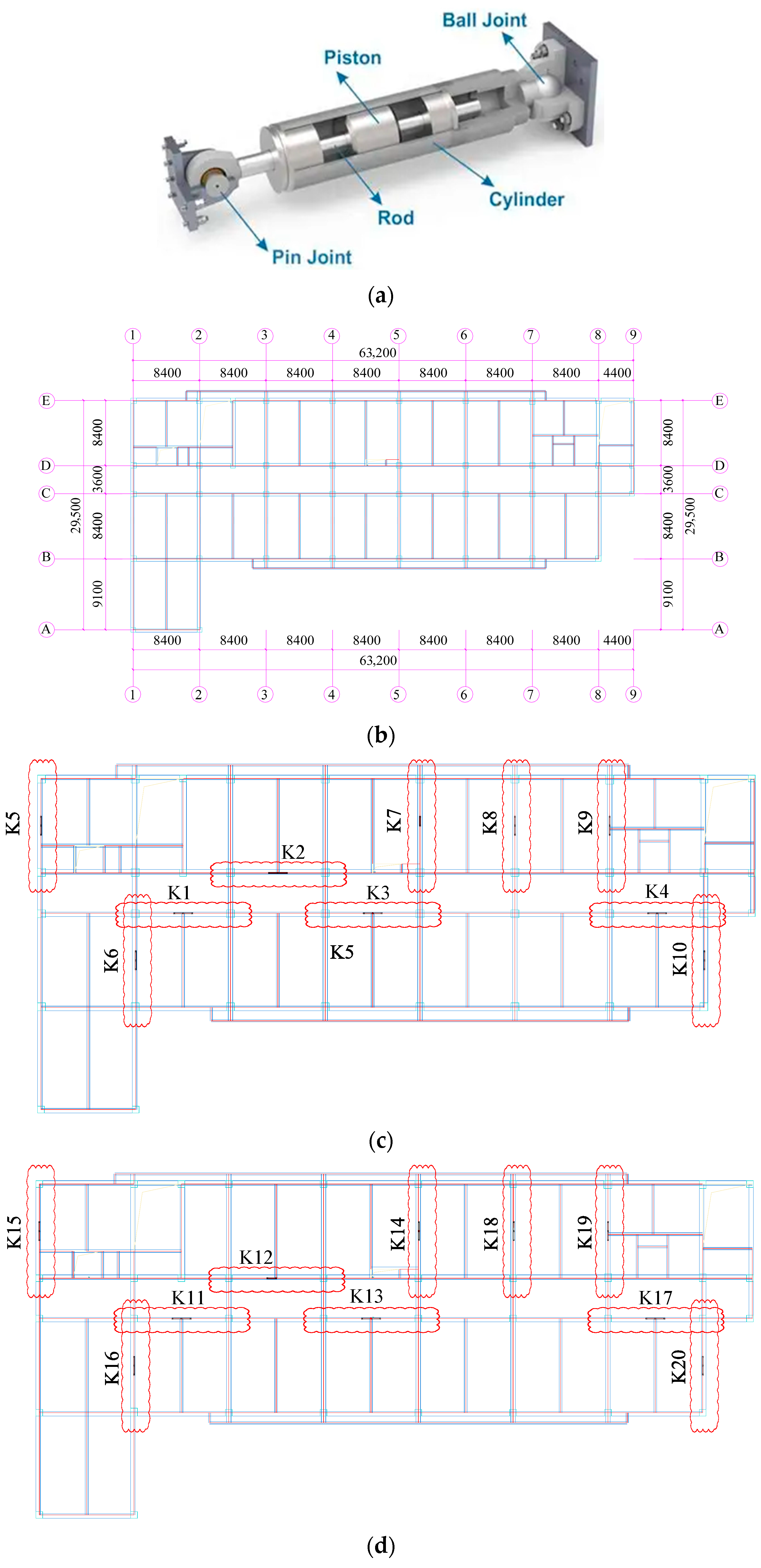
As velocity-dependent energy dissipation devices, viscous fluid dampers (VFDs) dissipate seismic energy through fluid viscous resistance. This study employs single-diagonal VFDs (Figure 3a), installed on the first to the third stories. Various dampers are labeled with the prefix ‘K’ (e.g., K10 denotes the tenth damper) and arranged following the principles of “perimeter distribution, symmetry, uniformity, and dispersion” (Figure 3b–d). The quantity and parameters of configured dampers are detailed in Table 5.
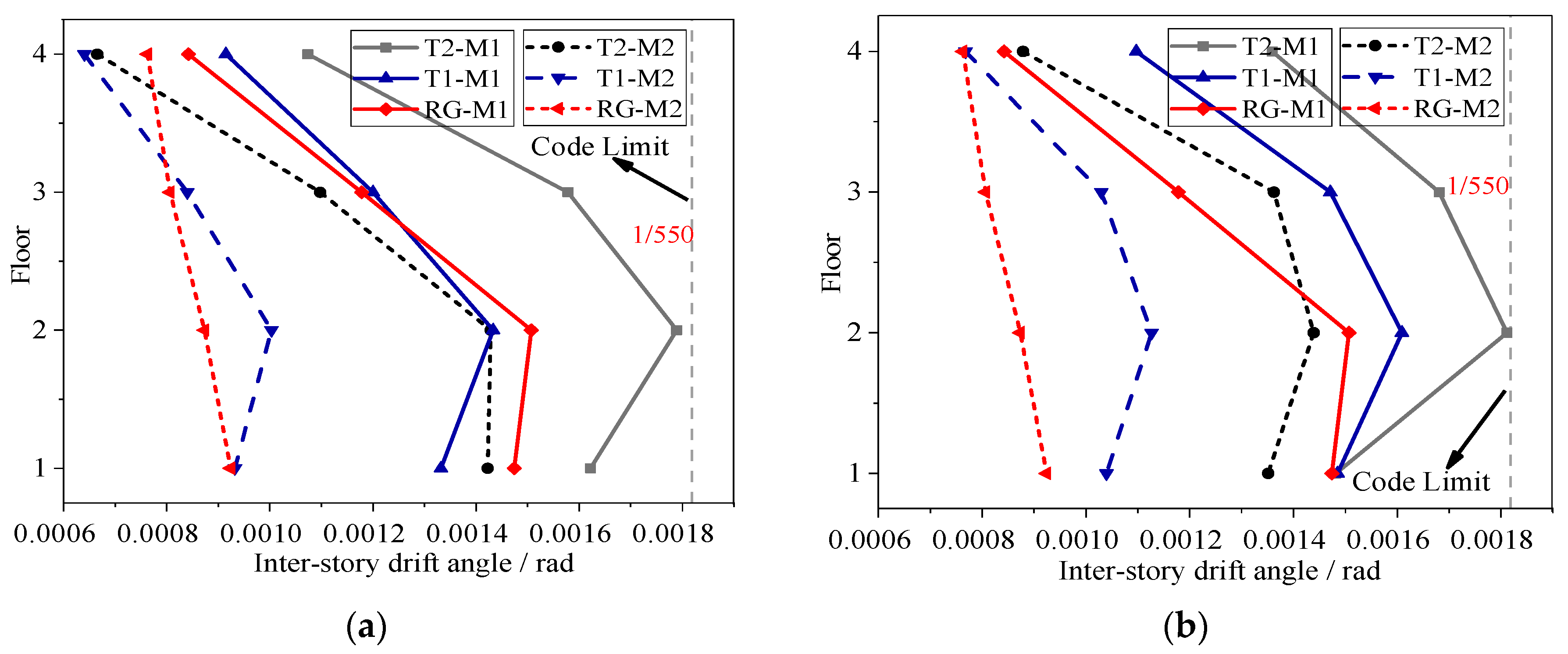
In subsequent analyses (Section 5), the notation RG(T1/T2)-M1(M2) is adopted to represent the inter-story drift angles of different models under various ground motion excitations. The symbol before the hyphen denotes the earthquake record, while the symbol after the hyphen indicates either the initial model (M1) or the retrofitted model with dampers (M2). For instance, RG-M1 represents the inter-story drift angle of the original model under an artificially generated accelerogram; and T2-M2 denotes the inter-story drift angle of the retrofitted model subjected to T2 excitation.

5. Nonlinear Response Analysis

5.1. Dynamic Characteristics of Structure

The dynamic characteristics of the structure are presented in Table 6, where Ux, Uy, and Uz represents the mass participation coefficients in different directions, reflecting the translational and torsional effects of the structure in ETABS. The first three vibration modes are predominantly translational vibrations: the first mode is mainly Y-direction translation, while the second mode is primarily X-direction translation. Notably, the Z-direction mass participation coefficients (Uz) for all three modes are zero, indicating that no torsional effect occurs in the structure.

5.2. Nonlinear Response Analysis Under Frequent Earthquakes (FEs)

5.2.1. Structural Displacement Response

Figure 4 and Figure 5 present the displacement responses of the structure before and after retrofitting under frequent earthquakes (FEs). The results demonstrate a significant reduction in inter-story drift angle (ISDA) at all levels after implementing the energy dissipation system. As shown in Figure 4, the viscous dampers effectively reduced ISDA under different ground motions. According to the envelope values of ISDA in Table 7, the reduction ratios range between 10% and 40%, confirming the consistent effectiveness of the proposed damping system across various seismic scenarios.
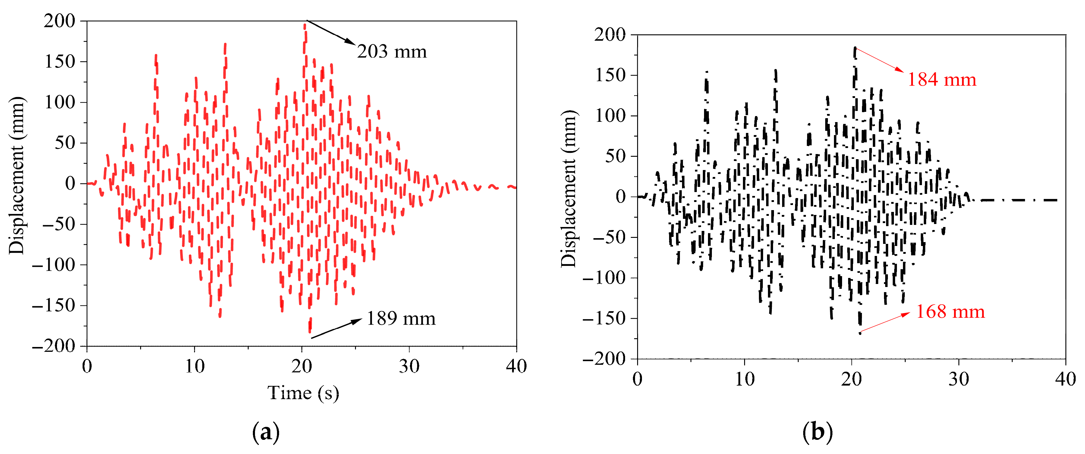
The column-top displacement responses (Figure 5) reveal reductions from 203 mm to 184 mm (9.4%) in the positive direction and from 189 mm to 168 mm (11.1%) in the negative direction. These results validate the remarkable control effect of viscous dampers on structural displacement responses, demonstrating that their energy dissipation mechanism effectively restrains seismic-induced deformations and enhances overall seismic performance.

5.2.2. Base Shear Analysis

Base shear, a critical parameter in seismic design, directly reflects the dynamic response characteristics of structures under earthquakes and serves as an indicator of both structural seismic performance and energy input levels [53,54]. In structural vibration control theory, base shear represents one of the primary driving forces of a dynamic response, making its reduction through optimized design strategies a crucial approach for seismic performance enhancement.
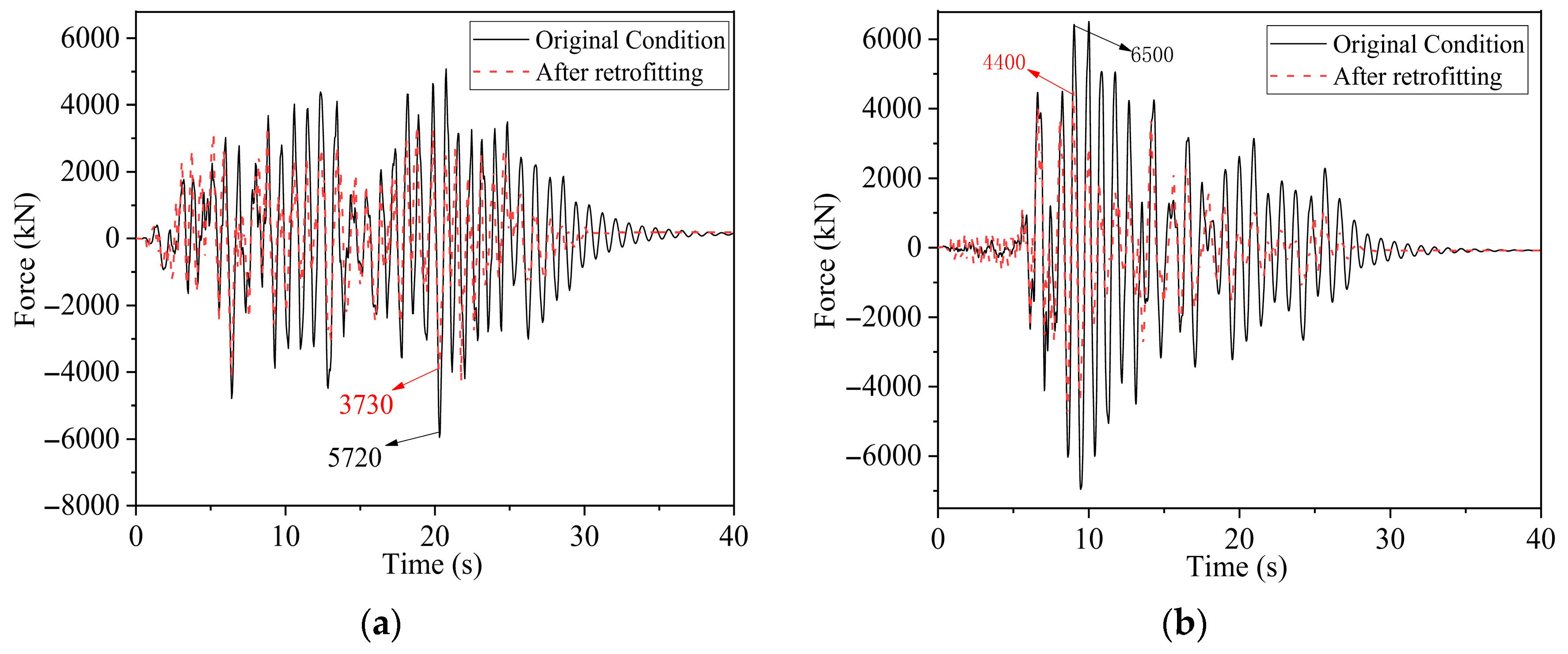
Figure 6 presents a comparative analysis of base shear variations before and after structural retrofitting. The analytical results demonstrate significant reductions in both principal directions, with the X-direction base shear decreasing from 5720 kN to 3730 kN (representing a 34.6% reduction) and the Y-direction base shear reducing from 6500 kN to 4400 kN (corresponding to a 32.3% reduction).
These data confirm the effectiveness of the proposed viscous damper configuration in significantly reducing structural internal forces during earthquakes. The comparable reduction ratios in both principal directions indicate the well-balanced control capacity of the damping system, which is essential for ensuring structural stability under multi-directional seismic excitations and validates the rationality of the design scheme.

5.2.3. Force–Displacement Hysteresis Behavior

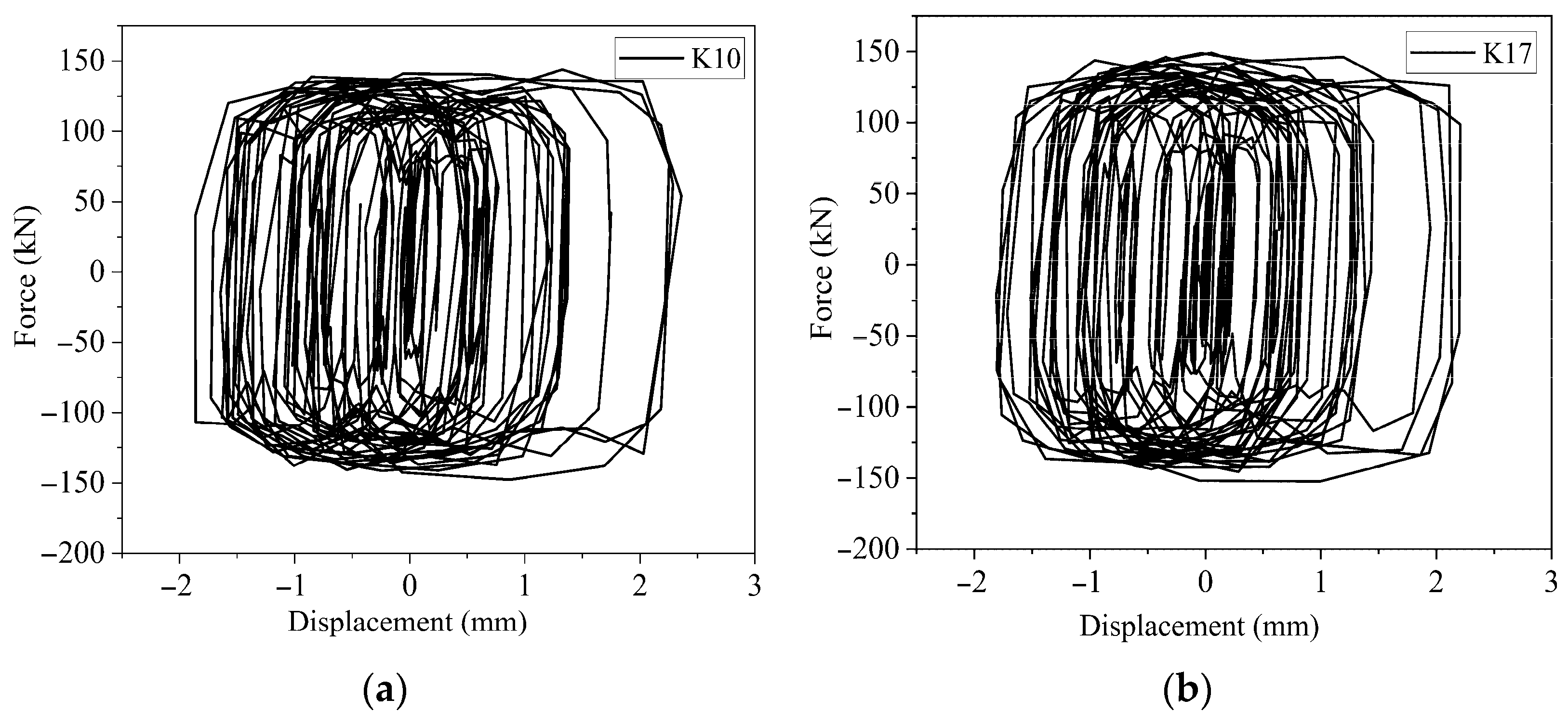
Figure 7 illustrates the force–displacement hysteresis curves of the viscous dampers under frequent earthquake excitations. The observed rectangular-shaped hysteresis loops demonstrate excellent agreement with the theoretical energy dissipation mechanism of viscous dampers [55,56], confirming their effective operational status. This characteristic hysteresis pattern verifies that the dampers have successfully engaged in energy dissipation during seismic events.
The force–displacement response analysis revealed specific performance metrics for individual dampers. In the X-direction, Damper K17 exhibited a peak force output of 160 kN, achieving 40% of its design capacity. Similarly, Damper K10 in the Y-direction generated a peak force of 150 kN, reaching 37.5% of its designated capacity. These results demonstrate that the damping system actively participates in seismic resistance even under frequent earthquake conditions, exhibiting a satisfactory energy dissipation capacity.

5.2.4. Energy Dissipation and Additional Damping Ratios

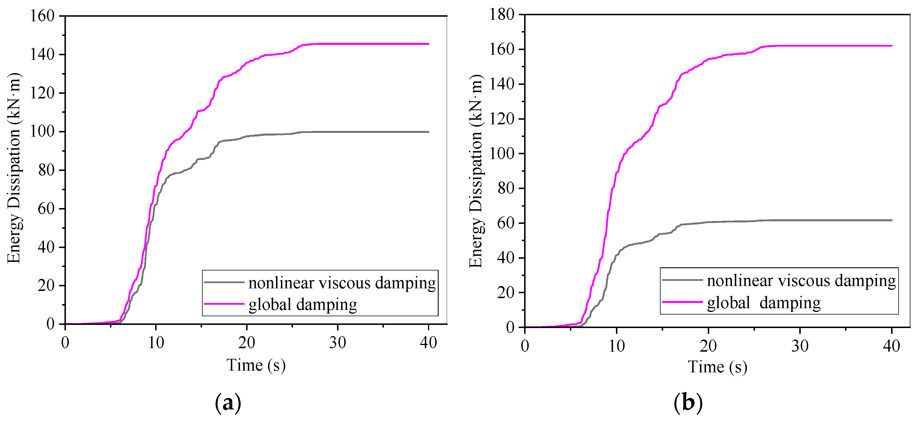
Figure 8 presents the energy dissipation of the structure under FEs. The analysis reveals that X-direction dampers dissipated 100 kN·m of energy, accounting for 66.7% of total energy dissipation, while Y-direction dampers dissipated 65 kN·m, representing 40% of the total. Following the Technical Specification for Seismic Energy Dissipation of Buildings (JGJ 297-2013) [57], the additional damping ratios were quantified as 3.3% (X-direction) and 2.0% (Y-direction) under FEs.

5.3. Nonlinear Response Analysis Under Maximum Considered Earthquake (MCE)

The nonlinear time history analysis under MCE conditions [58,59] was conducted considering material nonlinearity while adopting the small deformation assumption and neglecting geometric nonlinear effects. The numerical solution was obtained using the Hilber–Hughes–Taylor (HHT) implicit time integration method [55], which effectively suppresses high-frequency numerical oscillations through numerical damping parameters. The analysis parameters were set as β = 0.25 and γ = 0.5, ensuring computational stability while accurately capturing the nonlinear dynamic response characteristics of the structure.

5.3.1. Nonlinear Displacement Response

Figure 9 presents the distribution of inter-story drift angle (ISDA) under MCE-level excitation (0.4 g PGA). The results demonstrate that the unretrofitted structure exhibited a maximum ISDA of 1/37 (X-direction) and 1/38 (Y-direction), exceeding both the code-specified limit of 1/50 stipulated in the Code for Seismic Design of Buildings (GB 50011-2010) [44] and indicating potential severe structural damage or even partial collapse under such extreme seismic events.
The seismic retrofitting system significantly improved the structural performance, reducing the maximum ISDA to 1/55 (X-direction) and 1/60 (Y-direction), corresponding to reduction ratios of 33% and 37%, respectively. This performance enhancement can be attributed to (i) the optimized configuration of viscous dampers, which effectively dissipated seismic input energy, and (ii) the rational redistribution of structural stiffness, which improved the global deformation pattern.

5.3.2. Force–Displacement Hysteresis Behavior

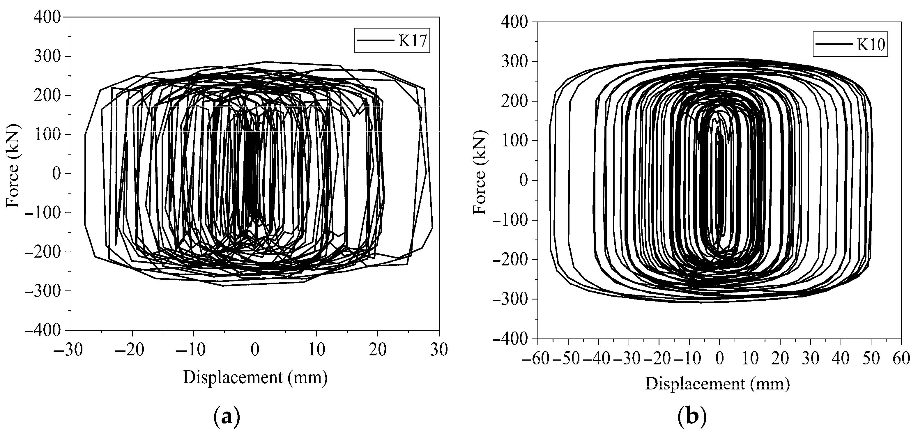
Figure 10 shows the force–displacement hysteresis curves of viscous dampers under 0.4 g PGA excitation. The distinct rectangular-shaped hysteresis loops demonstrate an excellent energy dissipation capacity during strong ground motions. Specifically, damper K17 in the X-direction reached a peak force of 300 kN (75% of its 400 kN design capacity), while damper K10 in the Y-direction achieved 320 kN (80% of design capacity). Notably, both dampers maintained 20–25% unused capacity reserves, providing critical safety margins for potential beyond-design-basis earthquake scenarios. Here, safety margin refers to the additional load-bearing capacity reserved in engineering design, characterizing the performance reserve of a structure or component before reaching its limit state.

5.3.3. Energy Dissipation and Additional Damping Ratios

Under MCE scenarios (Figure 11), the dampers demonstrated a significantly enhanced energy dissipation capacity, with X-direction total dissipation reaching 1700 kN·m (74% of total energy) and Y-direction total dissipation attaining 1800 kN·m (47% of total energy). The corresponding additional damping ratios increased to 3.7% (X-direction) and 2.4% (Y-direction), demonstrating that the viscous dampers effectively activated their energy dissipation mechanisms during MCE events and that the system successfully absorbed seismic input energy, substantially reducing plastic damage in the primary structure.

5.3.4. Analysis of Structural Nonlinear Behavior Development

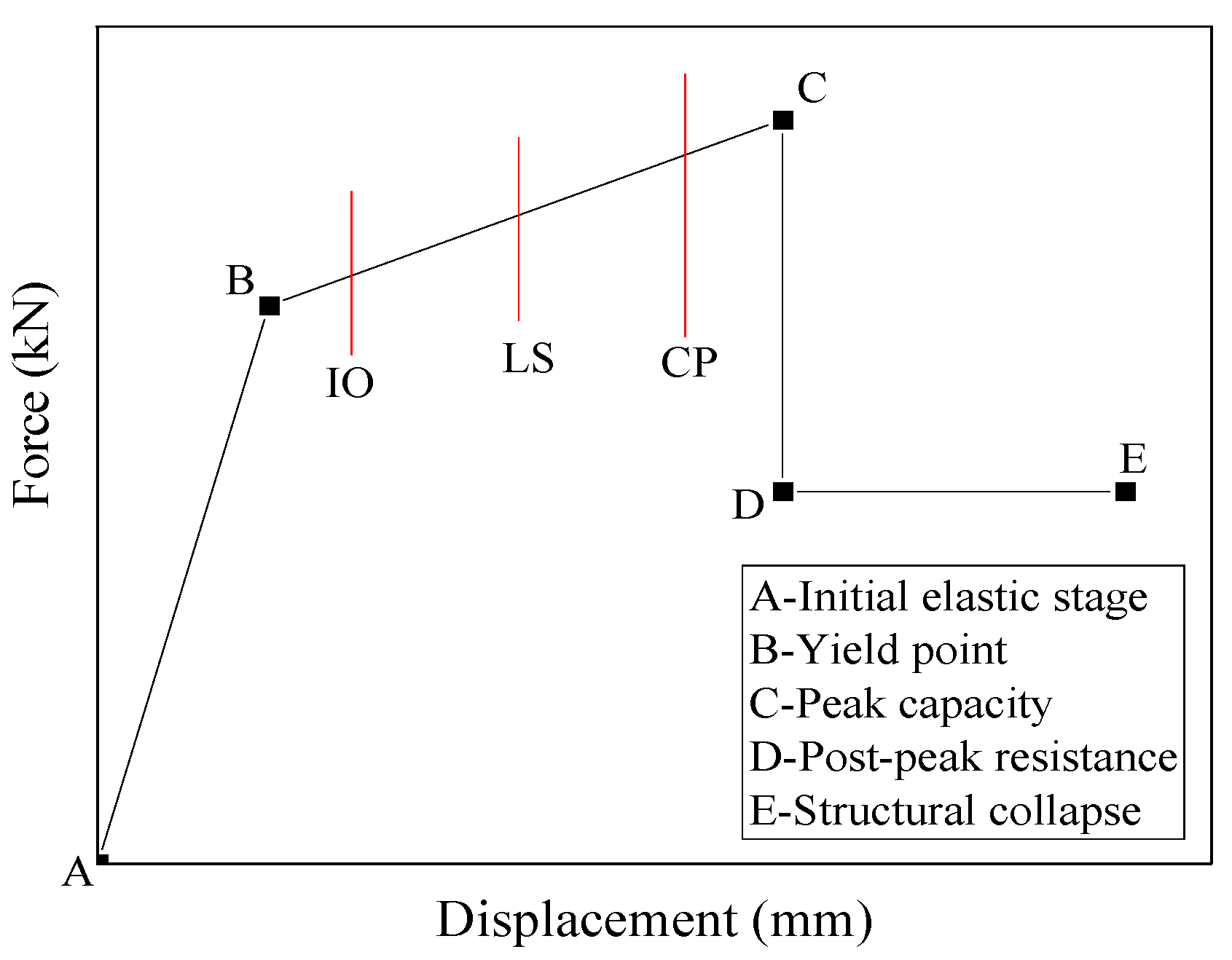
Following the modeling guidelines of FEMA-356 [60], this study employed a nonlinear beam–column element approach incorporating material nonlinear constitutive relationships. The post-yield behavior was simulated through plastic hinge mechanisms, with refined backbone curves considering stiffness degradation (Figure 12), which comprehensively characterize the structural mechanical evolution from elastic phase to ultimate state. The performance levels were defined as Immediate Occupancy (IO), Life Safety (LS), and Collapse Prevention (CP) [52]. Specifically, beam ends utilized P-M3 interaction hinges to account for moment–axial force coupling effects; columns employed fiber-based P-M2-M3 hinge models with section discretization, enabling precise simulation of biaxial moment interactions.
Figure 13 illustrates the nonlinear response characteristics under MCE-level excitation (0.4 g PGA). Initial phase: IO-level plastic hinges first formed at beam ends in lower stories (undamped configuration). Development phase: Hinges propagated vertically to upper floors with LS-level hinges appearing at column ends. Ultimate phase: Hinges primarily concentrated at beam–column joints in second/third stories, reaching maximum CP state. The complete process analysis confirms that the structural response remained within the BC hardening branch of the backbone curve without entering the CD degradation stage, satisfying collapse prevention safety margin requirements.

6. Discussion

This research significantly advances the field of seismic retrofitting for RC frame structures through its comprehensive evaluation of viscous fluid dampers (VFDs). While previous studies have primarily focused on VFD applications in high-rise or steel structures [18,20,30,31,32,33,34], this work provides critical insights into their effectiveness for mid-rise RC frames—a structural typology that has received limited attention despite its widespread use in seismically vulnerable regions [35,36,37,38].
Compared to existing research, this study offers three key advancements:
(i)
Performance Benchmarking: By directly comparing damped and undamped structural responses using nonlinear time-history analysis, the study establishes clear performance metrics (e.g., 66.7–74% energy dissipation contribution) that were previously lacking for RC frames.
(ii)
Practical Implementation Guidelines: The validated perimeter-based damper configuration addresses a critical gap in the literature by providing engineers with a replicable design strategy that balances torsional resistance and energy dissipation uniformity.
(iii)
The nonlinear response analysis method employed in this study is superior to traditional response spectrum methods, because it considers earthquake motion duration, peak acceleration, and spectral characteristics.
This research bridges an important gap between theoretical damper studies and practical applications, offering engineers both performance data and implementation strategies that were previously unavailable for mid-rise RC frames. The demonstrated effectiveness of VFDs in meeting seismic code requirements while providing safety margins suggests they should be considered as a primary retrofitting option for similar structures in high-seismicity regions.

7. Conclusions

This study investigated the seismic retrofitting of an existing RC frame structure using viscous fluid dampers (VFDs) to enhance performance in high-seismicity regions. Key findings and contributions include the following:
(1)
Effective drift control: VFDs reduced inter-story drift angles by 10–40% under FEs and 33–37% under the MCE, ensuring compliance with stringent code limits (1/50 under the MCE). This demonstrates their efficacy in mitigating deformation-induced damage.
(2)
Force and energy dissipation: Base shear reductions of 34.6% (X) and 32.3% (Y) under FEs highlight VFDs’ ability to redistribute seismic forces. Dampers contributed 66.7% (X) and 40% (Y) of total energy dissipation under FEs, increasing to 74% (X) and 47% (Y) under the MCE, with additional damping ratios of 3.3–3.7% (X) and 2.0–2.4% (Y).
(3)
Damage mitigation: Plastic hinge formation was delayed and controlled, preventing collapse-level damage. The structure remained within the Life Safety (LS) to Collapse Prevention (CP) performance range under the MCE.
(4)
Practical implications: The study provides a validated framework for retrofitting RC frames in critical infrastructure (e.g., schools, hospitals) in seismic zones. The symmetric, perimeter-based damper configuration proved effective, offering a replicable design strategy.
Future research should explore the following: A comprehensive understanding of the nonlinear structural response when applying VFDs to RC frame structures requires the analysis of various parameters [61]. The work presented in this paper is only a preliminary step. Simultaneously considering frequent and rare earthquakes, different VFD configurations, and varying parameter settings (e.g., temperature, cracks, etc.) in a single study is a challenging task. Therefore, the next phase of our research will focus on investigating the nonlinear response of VFDs in RC frame structures under variable parameter conditions.

Author Contributions

Methodology, Software, Investigation, Writing—Original Draft, Project Administration, Funding Acquisition, P.M.; Conceptualization, Writing—Review and Editing, S.Y. All authors have read and agreed to the published version of the manuscript.

Funding

This research was funded by the Lanzhou Science and Technology Plan Project (grant no. 2024–9–302) and the Natural Science Foundation of China (grant no. 51978401).

Data Availability Statement

The original contributions presented in this study are included in the article; further inquiries can be directed to the corresponding authors.

Conflicts of Interest

P.M. and S.Y. were employed by Lanzhou Institute of Technology, Lanzhou, China. All authors declare that this research was conducted in the absence of any commercial or financial relationships that could be construed as potential conflicts of interest.

References

  1. Zhang, Z.; Zhang, J. Design And Analysis of Energy Dissipation and Vibration Reduction of Reinforced Concrete Frame Structure. Highlights Sci. Eng. Technol. 2023, 51, 21–26. [Google Scholar] [CrossRef]
  2. Qu, Z.; Zhu, B.; Cao, Y.; Fu, H. Rapid report of seismic damage to buildings in the 2022 M 6.8 Luding earthquake, China. Earthq. Res. Adv. 2023, 3, 11–30. [Google Scholar] [CrossRef]
  3. De Stefano, M.; Tanganelli, M.; Viti, S. Variability in Concrete Mechanical Properties as a Source of In-Plan Irregularity for Existing RC Framed Structures. Eng. Struct. 2014, 59, 161–172. [Google Scholar] [CrossRef]
  4. Ye, L.; Lu, X. Analysis on seismic damage of buildings in the Wenchuan earthquake. J. Build. Struct. 2008, 29, 1–9. [Google Scholar] [CrossRef]
  5. Pan, Y.; Fan, Y.; Ren, Y.; Yang, B.; Hou, J.; Xiong, Y. Typical seismic damage investigation and analysis in Mountain area after Ms 6.1 Lushan earthquake. China Civ. Eng. J. 2023, 56, 35–48. [Google Scholar] [CrossRef]
  6. Vitiello, U.; Asprone, D.; Di Ludovico, M.; Prota, A. Life-Cycle Cost Optimization of the Seismic Retrofit of Existing RC Structures. Bull. Earthq. Eng. 2017, 15, 2245–2271. [Google Scholar] [CrossRef]
  7. Ma, P.; Xin, R.; Yao, J. Assessment of Failure Mode and Seismic Performance of Damaged Masonry Structures Retrofitted with Grout-Injected Ferrocement Overlay Reinforcement (GFOR). Constr. Build. Mater. 2021, 305, 124778. [Google Scholar] [CrossRef]
  8. Giancarlo, M.; Gaetano, M.; Andrea, P.; Marisa, P. In-Plane Shear Performance of Masonry Panels Strengthened with FRP. Compos. Part B Eng. 2007, 38, 887–901. [Google Scholar] [CrossRef]
  9. Zhou, D.; Lei, Z.; Wang, J. In-Plane Behavior of Seismically Damaged Masonry Walls Repaired with External BFRP. Compos. Struct. 2013, 102, 9–19. [Google Scholar] [CrossRef]
  10. Ma, P.; Xin, R.; Yao, J. An Investigation of Bond Behavior between Composite Materials (CFRP, GWMM, KPGC) and Substrates (Brick and Concrete) for Strengthening Existing Masonry Structures. Constr. Build. Mater. 2023, 409, 134019. [Google Scholar] [CrossRef]
  11. Cheng, S.; Yin, S.; Jing, L. Comparative Experimental Analysis on the In-Plane Shear Performance of Brick Masonry Walls Strengthened with Different Fiber Reinforced Materials. Constr. Build. Mater. 2020, 259, 120387. [Google Scholar] [CrossRef]
  12. Deng, M.; Yang, S. Cyclic Testing of Unreinforced Masonry Walls Retrofitted with Engineered Cementitious Composites. Constr. Build. Mater. 2018, 177, 395–408. [Google Scholar] [CrossRef]
  13. Yang, X.; Gao, W.-Y.; Dai, J.-G.; Lu, Z.-D. Shear Strengthening of RC Beams with FRP Grid-Reinforced ECC Matrix. Compos. Struct. 2020, 241, 112120. [Google Scholar] [CrossRef]
  14. Tetta, Z.C.; Bournas, D.A. TRM vs FRP Jacketing in Shear Strengthening of Concrete Members Subjected to High Temperatures. Compos. Part B Eng. 2016, 106, 190–205. [Google Scholar] [CrossRef]
  15. Raoof, S.M.; Bournas, D.A. TRM versus FRP in Flexural Strengthening of RC Beams: Behaviour at High Temperatures. Constr. Build. Mater. 2017, 154, 424–437. [Google Scholar] [CrossRef]
  16. Papanicolaou, C.G.; Triantafillou, T.C.; Papathanasiou, M.; Karlos, K. Textile Reinforced Mortar (TRM) versus FRP as Strengthening Material of URM Walls: Out-of-Plane Cyclic Loading. Mater. Struct. 2007, 41, 143–157. [Google Scholar] [CrossRef]
  17. De Felice, G.; De Santis, S.; Garmendia, L.; Ghiassi, B.; Larrinaga, P.; Lourenço, P.B.; Oliveira, D.V.; Paolacci, F.; Papanicolaou, C.G. Mortar-Based Systems for Externally Bonded Strengthening of Masonry. Mater. Struct. 2014, 47, 2021–2037. [Google Scholar] [CrossRef]
  18. Benavent-Climent, A.; Oliver-Saiz, E.; Donaire-Ávila, J. Seismic Retrofitting of RC Frames Combining Metallic Dampers and Limited Strengthening with FRP/SRP Applying Energy-Based Methods. Soil Dyn. Earthq. Eng. 2024, 177, 108432. [Google Scholar] [CrossRef]
  19. Alhamdany, A.M.A.; Dilsiz, A. Comparative Evaluation of Shear Walls and Fluid Viscous Dampers in Seismic Retrofitting of RC Public School Buildings. Structures 2025, 72, 108231. [Google Scholar] [CrossRef]
  20. Li, Z.; Shu, G. Optimal Placement of Metallic Dampers for Seismic Upgrading of Multistory Buildings Based on a Cost-effectiveness Criterion Using Genetic Algorithm. Struct. Des. Tall Build. 2019, 28, e1595. [Google Scholar] [CrossRef]
  21. Parulekar, Y.M.; Reddy, G.R. Passive response control systems for seismic response reduction: A state-of-the-art review. Int. J. Str. Stab. Dyn. 2009, 09, 151–177. [Google Scholar] [CrossRef]
  22. Zhou, Y.; Shang, C.; Zhang, C. Progress in research and application of energy-dissipated technology. Build. Struct. 2019, 49, 33–48. [Google Scholar] [CrossRef]
  23. Zhou, Y.; Shang, C.; Fang, D.; Tang, F. Advances in research and application of energy dissipation technology: Insights from the 18th World Conference on Earthquake Engineering. World Earthq. Eng. 2025, 41, 58–71. [Google Scholar] [CrossRef]
  24. Shao, Z.; Liu, Q.; Pan, Z.; Wang, W. Research on the earthquake trend in China’s land area in the next 1–3 years and the prediction of the urgency of earthquake occurrence in long-term hazardous areas. Earthquake 2025, 45, 214–261. [Google Scholar]
  25. Lv, D.; Wang, C.; Dong, Y.; Feng, Y. Research progress of uniform-risk seismic design theory of building structures. J. Build. Struct. 2024, 45, 1–30. [Google Scholar] [CrossRef]
  26. Pan, Y.; Gao, H.; Xiong, Y.; Wu, X. Seismic damage investigation and analysis of energy-dissipated and seismically isolated buildings in Ms 6.8 Luding earthquake. J. Build. Struct. 2023, 44, 122–136. [Google Scholar] [CrossRef]
  27. Ye, L.; Liu, Y.; Dai, G. Application study of energy dissipation and vibration reduction technology of medical buildings in high intensity area. Build. Struct. 2023, 53, 100–105, 130. [Google Scholar] [CrossRef]
  28. Hou, H.; Wang, Q.; Zhang, X. Application of combination damping technology in seismic strengthening of a hospital building. Earthq. Resist. Eng. Retrofit. 2025, 47, 125–131, 147. [Google Scholar] [CrossRef]
  29. Lan, X.; Zhang, X.; Shao, Y.; Zhang, L.; Su, H.; Pan, W. Study on the influence of viscous damper parameters on the damping efficiency of frame structure. J. Nat. Disasters 2024, 33, 176–187. [Google Scholar] [CrossRef]
  30. Yang, J.; Liu, Y.; Tian, H.; Li, C.; Liu, B. Design of energy dissipation and damper optimization for a high-rise building. China Earthq. Eng. J. 2023, 45, 835–844. [Google Scholar] [CrossRef]
  31. Zhou, Y.; Qiao, S.; Shu, Z. Practical energy dissipation design of steel structures with viscous dampers. Earthq. Eng. Eng. Dyn. 2022, 42, 1–10. [Google Scholar] [CrossRef]
  32. Xue, J.; Zhang, C.; Wei, L.; Sui, Y.; Liang, Y.; Luo, Z. Analysis of damping effect of super high-rise frame-core tube structure with viscous damper. J. Xi’an Univ. Archit. Technol. 2020, 52, 21–29. [Google Scholar] [CrossRef]
  33. Shao, B.; Zou, H.; Lin, J.; Yao, F.; Wang, L.; Cui, J.; Xu, H. Research on the Viscous Damping Effect of Concentrically Braced Concrete-Filled Steel Tubular Frame Structure. Prog. Steel Build. Struct. 2023, 25, 75–84. [Google Scholar] [CrossRef]
  34. He, W.; Huang, X.; Zhang, Q.; Xu, H.; Liu, W. Theoretical and experimental investigation on high-performance viscous damper. J. Vib. Eng. 2021, 34, 879–888. [Google Scholar] [CrossRef]
  35. Aghlara, R.; Tahir, M.M. A Passive Metallic Damper with Replaceable Steel Bar Components for Earthquake Protection of Structures. Eng. Struct. 2018, 159, 185–197. [Google Scholar] [CrossRef]
  36. Javadinasab Hormozabad, S.; Zahrai, S. Innovative Adaptive Viscous Damper to Improve Seismic Control of Structures. J. Vib. Control 2019, 25, 1833–1851. [Google Scholar] [CrossRef]
  37. Li, C.; Wu, X.; Hu, W.; Zhang, X. Application of performance-based seismic retrofit for reinforcement and reconstruction of existing structure. Build. Struct. 2022, 52, 2079–2083. [Google Scholar] [CrossRef]
  38. Zhang, X.; Yue, Q. Development on theory and technology on the evaluation, strengthening and retrofitting of existing structures. J. Shandong Jianzhu Univ. 2021, 36, 76–82. [Google Scholar]
  39. Asgari, A.; Bagheri, M.; Hadizadeh, M. Advanced Seismic Analysis of Soil-Foundation-Structure Interaction for Shallow and Pile Foundations in Saturated and Dry Deposits: Insights from 3D Parallel Finite Element Modeling. Structures 2024, 69, 107503. [Google Scholar] [CrossRef]
  40. Forcellini, D. Key Parameters to Model the Mutual Effects Between Base Isolation (BI) and Soil–Structure Interaction (SSI). Appl. Sci. 2024, 14, 11703. [Google Scholar] [CrossRef]
  41. Bray, J.D.; Sancio, R.B.; Durgunoglu, T.; Onalp, A.; Youd, T.L.; Stewart, J.P.; Seed, R.B.; Cetin, O.K.; Bol, E.; Baturay, M.B.; et al. Subsurface Characterization at Ground Failure Sites in Adapazari, Turkey. J. Geotech. Geoenviron. Eng. 2004, 130, 673–685. [Google Scholar] [CrossRef]
  42. Moss, R.E.S.; Collins, B.D.; Whang, D.H. Retesting of Liquefaction/Nonliquefaction Case Histories in the Imperial Valley. Earthq. Spectra 2005, 21, 179–196. [Google Scholar] [CrossRef]
  43. GBJ 11-1989; Specifications for Antiseismic Construction Design. General Administration of Quality Supervision: Beijing, China, 1989.
  44. GB 50011-2010; Code for Seismic Design of Buildings. China Architecture & Building Press: Beijing, China, 2010.
  45. Regulations on Seismic Management of Construction Engineering (State Decree No. 744). Available online: https://www.gov.cn/gongbao/content/2021/content_5631815.htm (accessed on 28 June 2025).
  46. He, X.; Zhou, Y.; Tian, Y.; Wang, W. Research on application of hybrid energy dissipation technology in a public medical structure based on “ Regulation on the administration of earthquake resistance of construction projects” issued by the government. Earthq. Resist. Eng. Retrofit. 2024, 46, 33–42. [Google Scholar] [CrossRef]
  47. GB 50009-2012; Load Code for the Design of Building Structures. China Architecture & Building Press: Beijing, China, 2013.
  48. Mander, J.B.; Priestley, M.J.N.; Park, R. Theoretical Stress—Strain Model for Confined Concrete. J. Struct. Eng. 1988, 114, 1804–1826. [Google Scholar] [CrossRef]
  49. Feng, Y.; Wu, P.; Liu, J.; Zhang, L. Hysteretic shear model based on Park three—Parameter hysteretic model. World Earthq. Eng. 2012, 28, 80–88. [Google Scholar]
  50. Long, Z.; Shen, W. A Maxwell Inerter Damper for Civil Structures: Modeling and Testing. Eng. Struct. 2025, 339, 120685. [Google Scholar] [CrossRef]
  51. Ikeda, Y.; Uhara, N. Application of Pole Allocation to Optimize Passive Viscous Dampers Represented by the Maxwell Model. Soil Dyn. Earthq. Eng. 2025, 188, 109037. [Google Scholar] [CrossRef]
  52. ASCE 41-17; Seismic Evaluation and Retrofit of Existing Buildings. American Society of Civil Engineers: Reston, VA, USA, 2017.
  53. Wu, K.; Chen, X.; Tao, Z.; Kong, L. Design method and engineering application of combined energy dissipation structure. J. Guangxi Univ. (Nat. Sci. Ed.) 2021, 46, 831–843. [Google Scholar] [CrossRef]
  54. Yuan, P.; Song, G.; Cao, X.; Wang, W.; Jiang, B.; Li, X. Shock-absorbing reinforcement design of a frame structure of Sinovac. Earthq. Resist. Eng. Retrofit. 2024, 46, 63–68. [Google Scholar] [CrossRef]
  55. Liao, X. Research on structure dynamic response analysis method. Build. Struct. 2016, 46, 22–26, 9. [Google Scholar] [CrossRef]
  56. Zheng, H.; Wang, T.; Wang, Z.; Meng, L.; Xu, G.; Zhang, J.; Dou, X. Parametric identification of Maxwell model for viscous damper based on real-time hybrid tests. J. Vib. Shock 2025, 44, 45–53, 106. [Google Scholar] [CrossRef]
  57. JGJ 297-2013; Technical Specification for Seismic Energy Dissipation of Buildings. China Architecture & Building Press: Beijing China, 2013.
  58. Whittle, J.K.; Williams, M.S.; Karavasilis, T.L.; Blakeborough, A. A Comparison of Viscous Damper Placement Methods for Improving Seismic Building Design. J. Earthq. Eng. 2012, 16, 540–560. [Google Scholar] [CrossRef]
  59. Wang, C.; Yu, X.; Wang, J.; Liu, F. Elastic-plastic analysis of a high-rise commercial and residential building in Zhuzhou under a rare earthquake. Earthq. Resist. Eng. Retrofit. 2024, 46, 10–16. [Google Scholar] [CrossRef]
  60. FEMA 356; Prestandard and Commentary for the Seismic Rehabilitation of Buildings. Federal Emergency Management Agency: Washington, DC, USA, 2000.
  61. Asgari, A.; Ahmadtabar Sorkhi, S.F. Wind Turbine Performance under Multi-Hazard Loads: Wave, Wind, and Earthquake Effects on Liquefiable Soil. Results Eng. 2025, 26, 104647. [Google Scholar] [CrossRef]
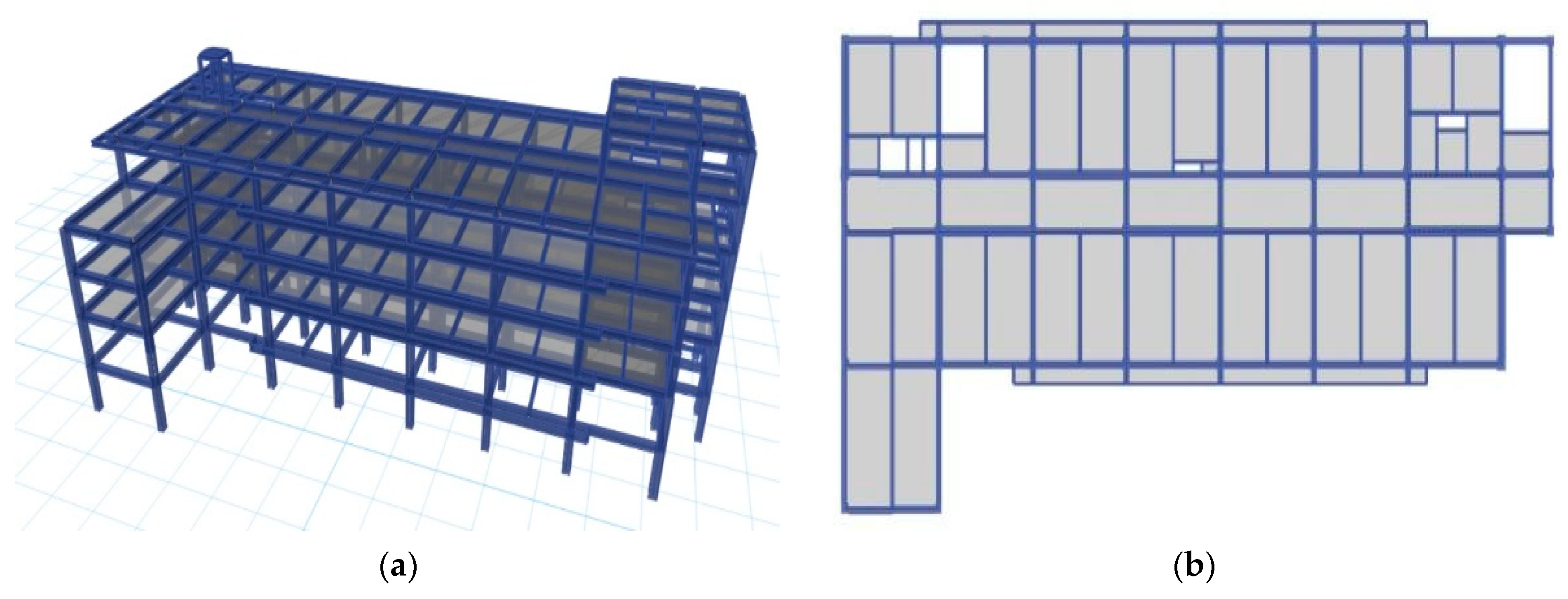
Figure 1. Detailed model of the main structure: (a) axonometric view; (b) plan view.
Infrastructures 10 00235 g001
Figure 2. The comparison between the code spectrum and the response spectrum.
Infrastructures 10 00235 g002
Figure 3. Photograph of the damper and schematic layout diagrams across floors: (a) photograph of the viscous damper [6]; (b) overall structural floor plan (unit: mm); (c) layout details on the first floor; (d) layout details on the second floor; (e) layout details on the third floor.
Infrastructures 10 00235 g003aInfrastructures 10 00235 g003b
Figure 4. Inter-story drift angle under FEs: (a) X-direction; (b) Y-direction.
Infrastructures 10 00235 g004
Figure 5. Column-top displacement under FEs: (a) original condition; (b) after retrofitting.
Infrastructures 10 00235 g005
Figure 6. Comparison of base shear under FEs: (a) X-direction; (b) Y-direction.
Infrastructures 10 00235 g006
Figure 7. Force–displacement hysteresis curves under FEs: (a) X-direction; (b) Y-direction.
Infrastructures 10 00235 g007
Figure 8. Energy dissipation under FEs: (a) X-direction; (b) Y-direction.
Infrastructures 10 00235 g008
Figure 9. Inter-story drift angle under MCE: (a) X-direction; (b) Y-direction.
Infrastructures 10 00235 g009
Figure 10. Force–displacement hysteresis curves under MCE: (a) X-direction; (b) Y-direction.
Infrastructures 10 00235 g010
Figure 11. Energy dissipation under MCE: (a) X-direction; (b) Y-direction.
Infrastructures 10 00235 g011
Figure 12. Plastic hinge backbone curve.
Infrastructures 10 00235 g012
Figure 13. Nonlinear time-history response characteristics under MCE: (a) initial phase; (b) development phase; (c) ultimate phase.
Infrastructures 10 00235 g013
Table 1. Comparison of structural mass.
Mass (t)PKPM (kg)ETABS (kg)Error (%)
Dead load921390352
Live load6556550
Total mass986896902
Table 2. Comparison of structural periods.
ModePKPM (s)ETABS (s)Error (%)
First mode0.820.8807
Second mode0.810.877
Third mode0.770.8105
Table 3. Comparison of structural shear forces.
FloorPKPM (kN)ETABS (kN)Error (%)
X-DirectionY-DirectionX-DirectionY-DirectionX-DirectionY-Direction
1F375136923500347476
2F609559595690556677
3F789876887334713477
4F914488948412812089
Table 4. Ground motion details for nonlinear dynamic evaluation.
IDEarthquake NamePGA (g)Time
Period (s)
Earthquake Ground
Motion Duration (s)
T1Northridge-01_NO_9420.110.3958.04
T2Irpinia, Italy-01_NO_2910.10.4176.80
RGArtificial ground wave0.070.4030.00
Table 5. Number of installed dampers and related parameters.
FloorNumberRelated Parameters
X-DirectionY-DirectionDamping
Coefficient
Damping
Exponent
Design
Damping Force
Damper
Stroke
3F24600 kN·m/s0.3400 kN·mm50 mm
2F46
1F46
In total26
Table 6. Dynamic characteristics of the structure.
ModePeriod (s)Directions of Vibration Modes
UxUyUz
10.8850.0010.7430.000
20.8760.7820.0010.000
30.8160.0010.0270.000
Table 7. Inter-story drift angle (envelope values).
FloorOriginal ConditionAfter RetrofittingDecreasing Amplitude Ratio
X-DirectionY-DirectionX-DirectionY-DirectionX-DirectionY-DirectionMean
4F1/9311/6801/15031/113838%40%39%
3F1/6341/5951/9111/73430%19%24%
2F1/5591/5521/7001/69520%21%20%
1F1/6161/6651/7031/74012%10%11%
Disclaimer/Publisher’s Note: The statements, opinions and data contained in all publications are solely those of the individual author(s) and contributor(s) and not of MDPI and/or the editor(s). MDPI and/or the editor(s) disclaim responsibility for any injury to people or property resulting from any ideas, methods, instructions or products referred to in the content.