1. Introduction
Pillar-less mining is an advanced coal extraction method that eliminates traditional protective coal pillars by optimising mine layouts, excavation techniques, and roadway positioning [
1,
2]. Its core principle is to arrange roadways along goaf edges or within stress-relief zones to avoid stress concentrations typically associated with pillar retention [
3]. Initially developed in the Soviet Union in the 1930s and subsequently improved worldwide [
4], Pillar-less mining has become an essential direction in coal mining. It reduces the risk of dynamic disasters such as rockbursts and coal-and-gas outbursts by eliminating pillar-induced stress concentrations [
5,
6]. Additionally, this method minimises resource loss, improves coal recovery rates, and extends mine operational lifespans [
7]. It also reduces roadway excavation, easing production scheduling conflicts. In high-gas mines, Pillar-less mining facilitates improved ventilation through Y-type ventilation arrangements, effectively controlling gas concentrations [
8,
9]. Moreover, this approach avoids isolated working faces, significantly enhancing overall mine safety and economic performance [
10,
11]. Consequently, Pillar-less mining is recognised as a crucial technology for achieving green and efficient coal resource extraction [
12].
Gob-side entry retaining (GER), a critical technique supporting pillar-less mining, has evolved significantly since its initial application in the 1950s [
13]. Early implementations in China involved waste-rock walls along thin-seam entries and internal timber supports. However, the significant compression of waste-rock walls, severe deformation of timber frames, slow manual construction, and low safety constrained its broader application. The design at this stage was passive, failing to accommodate dynamic rock deformation [
14].
From the 1960s to the 1970s, advancements in mining technologies led to the adoption of dense timber props, timber packs, and waste-rock belts as roadside supports in medium-thick seams, accompanied by trapezoidal I-beam sets internally [
15]. Although these methods provided improved stability, they lacked sufficient initial resistance and yielded inadequately under load, limiting their suitability primarily to low-gas mining environments. During the 1980s and 1990s, widespread mechanised longwall mining encouraged the adoption of roadside filling techniques, such as yieldable U-steel supports and quick-setting high-water-content filling materials [
16,
17]. Despite these innovations, passive support systems remained insufficiently adaptive to large-section deformation, and the complexity and high cost of filling technologies caused a reduction in their popularity. During this period, theoretical advancements emerged, including the rock-beam inclination theory proposed by British researcher S. Smethurst and support models developed by Chinese researchers such as Sun Henghu and Guo Yuguang, laying the groundwork for subsequent technical breakthroughs [
18]. Since 2000, the widespread adoption of bolt-mesh-cable support systems has marked a shift toward active support strategies [
19]. High-pretension bolts and cables have significantly enhanced surrounding-rock self-bearing capacities and roadway stability. Roadside supports have also become increasingly mechanised and advanced, incorporating high-performance filling materials such as high-water and paste fills. For example, Changcun Mine of the Lu’an Group successfully retained large-section gob-side entries in thick seams using combined bolt-beam-mesh supports and high-water filling. Concurrent theoretical progress has furthered understanding, with Li Huamin proposing a three-stage roof movement model and Xie Wenbing employing numerical simulations to clarify rock deformation mechanisms, guiding support parameter optimisation.
Nowadays, coordinated design integrating internal and roadside supports has become central to gob-side entry retaining technologies. Internal support systems primarily employ bolts, meshes, and cables, often supplemented by hydraulic props. Roadside support methods vary widely, including columns, walls, and fill-based structures. Among these, filling-type supports have become mainstream due to their high resistance and excellent sealing performance. Paste-filling technology, which uses coal gangue as aggregate, has reduced costs by nearly 50% compared to traditional high-water materials while effectively controlling roof subsidence. Nevertheless, mismatched support parameters under complex geological conditions and theoretical developments lagging behind practice remain critical issues restricting broader application.
Utilising pumping techniques and flexible forms, it rapidly forms strong supporting structures and effectively integrates solid waste resources, such as coal gangue, promoting greener mining practices. Developing low-cost, high-performance filling materials and improving flexible-formwork concrete mechanics and construction processes will significantly enhance the practicality and economic viability of gob-side entry retaining [
20,
21]. Additionally, integrating intelligent monitoring and stress-relief technologies will enable more precise rock control under complex geological conditions, facilitating broader adoption and advancement of pillar-less mining technologies. However, previous studies have seldom addressed gob-side entry retention under deep, hard-roof conditions using an integrated approach of presplitting blast-induced roof cutting and flexible formwork concrete support. This lack of established methodology for hard-roof, pillarless mining motivated our research.
This study adopts an integrated approach combining theoretical analysis, laboratory testing, numerical simulation, and field validation to develop a roof-cutting and support system capable of maintaining roadway stability without coal pillars. Key design parameters and a suitable high-strength backfill material are identified and verified, and the effectiveness of the proposed system is demonstrated through field trials. Each step builds upon the previous one to address the central question of maintaining roadway stability without coal pillars.
3. Theoretical Analysis
3.1. Mechanical Model
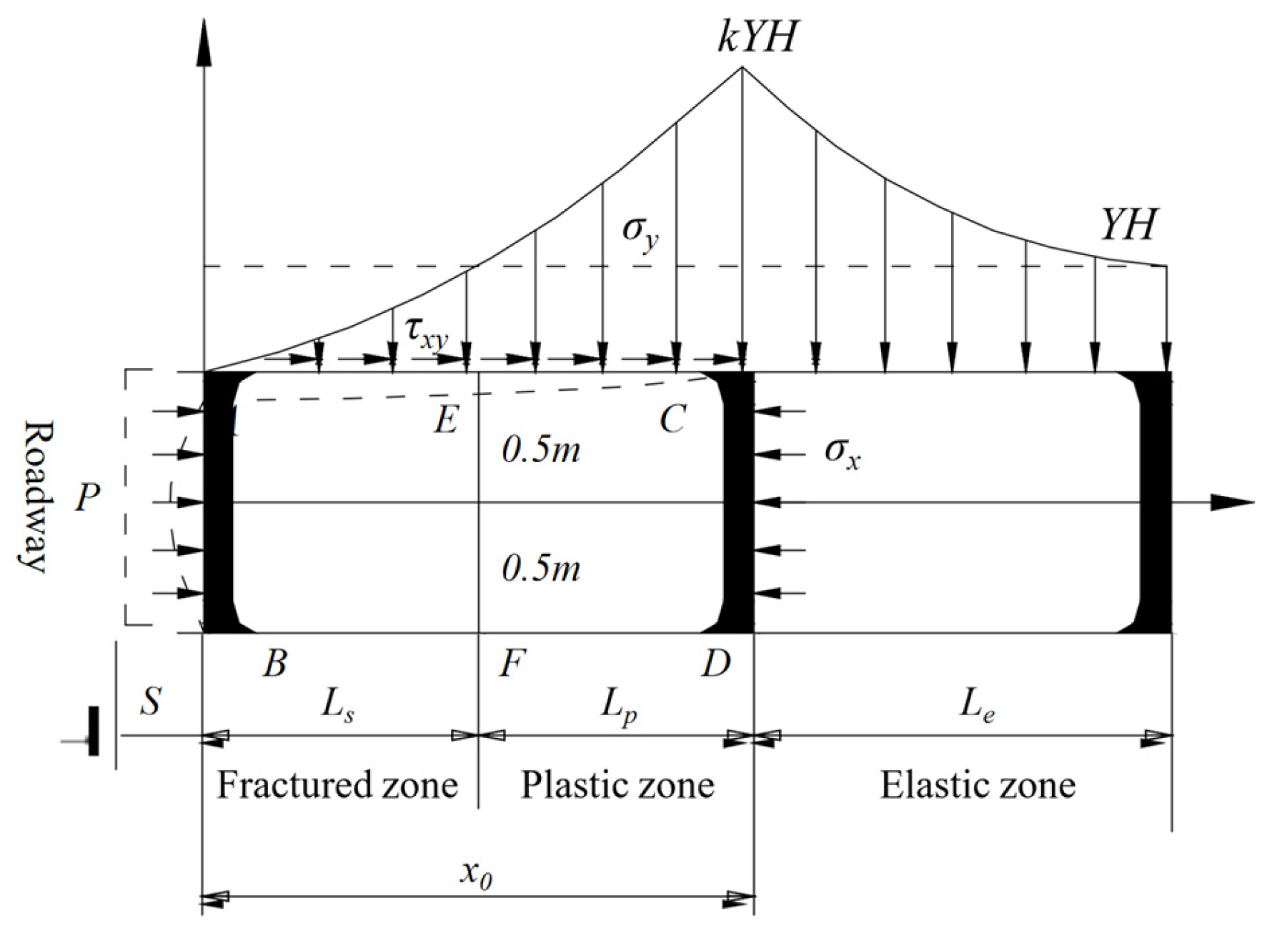
Ahead of and alongside the longwall face, abutment pressure induces a fractured–plastic zone in the coal rib (sidewall). Within this zone the coal mass attains a limit-equilibrium state. Because coal has a larger Poisson’s ratio than the roof and floor rocks, and because the interface cohesion
and internal-friction angle
are small, horizontal shear stresses develop along the coal-rock contacts and push the limit-equilibrium zone toward the roadway. For analytical clarity, the coal rib is idealised as a pillar of height
and unit thickness (
Figure 2). The interface stress system comprises:
—horizontal reaction supplied by the support system;
—average horizontal stress at across the full rib thickness;
—vertical (longitudinal) stress within the rib.
This representation is the basis for determining the width of the limit-equilibrium zone and related parameters.
For clarity, the key parameters in this model are defined as follows:
—bulk density;
—overburden depth;
—vertical stress concentration factor (the ratio of the vertical stress at to the weight of the overlying strata, );
—lateral pressure coefficient (the ratio of horizontal stress to vertical stress at );
—cohesion along the coal-rock interfaces (roof and floor);
—internal friction angle along the coal-rock interfaces (roof and floor).
These interface strength parameters are typically lower than the strength of the coal mass itself due to the weaker bonding at the coal-rock contacts [
22].
3.2. Stress and Displacement in the Limit-Equilibrium Zone
The following assumptions apply:
- 1.
Cohesion and internal-friction angle on the potential sliding surface are and .
- 2.
Stresses in the rib are symmetric about the horizontal axis (i.e., about a horizontal plane through the mid-height of the coal seam, assuming the roadway lies approximately centrally within the seam so that the stress distribution is roughly symmetric).
- 3.
At the boundary between the limit-equilibrium zone and elastic host rock
If
is the horizontal force acting on interface CD, the net horizontal force on zone ABCD is
Under this horizontal force and the overburden load, the rib undergoes elastic and plastic deformation. Neglecting creep, the total displacement in the plastic stage is
where
and
are the elastic and shear components, respectively.
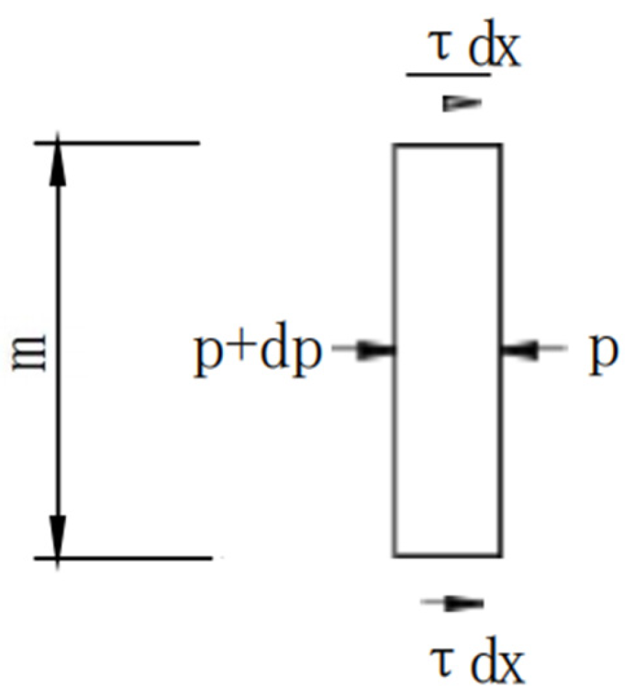
As illustrated in
Figure 3, let
denote the shear-stress gradient per unit length in the coal mass. Force equilibrium for an elemental slice then gives
where
is the axial force acting on an arbitrary cross-section
of unit roadway width.
According to Hooke’s law,
where
is the composite elastic modulus of the coal.
Substituting Equation (5) into Equation (4) yields the shear-stress gradient:
Assuming the shear stress at the coal–rock interface varies linearly with the corresponding shear displacement,
where
is the tangential stiffness of the interface—that is, the shear stress generated per unit shear displacement on a unit length of interface. This linear interface behaviour is a first-order approximation of the actual coal-rock interaction for small displacements, and is adopted here due to the lack of significant slip at the interface in the initial deformation stage.
Applying the boundary conditions provides closed-form solutions for shear displacement and stress throughout the limit-equilibrium zone; the interface shear stress obeys
Combining these expressions yields the vertical stress in the limit-equilibrium zone,
and the elastic displacement
,
At the roadway side
, the elastic and shear displacements are
giving the total displacement,
Relative roof-floor convergence squeezes additional coal into the roadway. Neglecting coal compressibility, the extruded cross-section equals the area lost within the limit-equilibrium zone. If the maximum roof convergence is
, this additional displacement is
where
is the design roadway height.
The total rib displacement is therefore
In summary, the inward movement of the coal rib is directly proportional to the lateral-pressure coefficient A and the stress-concentration factor k, and inversely proportional to the composite elastic modulus E.
3.3. Deformation and Failure Analysis of the Coal Rib
Depending on coal-mass properties, two cases are considered for the width of the limit-equilibrium zone:
Plastic condition (soft coal with low brittleness)—the rib undergoes only plastic deformation under roof loading, and the width of the crushed zone
is zero. At interface
EC, the shear stress satisfies
from which the limit-equilibrium width is
Equation (17) confirms that under purely plastic conditions (no crushed zone), the limit-equilibrium width increases linearly with the applied horizontal force . In contrast, when the vertical stress from the roof exceeds the coal’s strength, a crushed zone will form at the rib surface. If the stress stays below that strength, the rib undergoes only plastic deformation without a crushed zone. For instance, at the No. 3 coal seam, the uniaxial compressive strength of the coal is about 13.85 MPa. Given a roadway depth of 500 m, the vertical stress at the elastic-plastic boundary is approximately (with ≈ 2 and γ ≈ 26 kN/m3), which is on the order of 26 MPa—approaching or exceeding the coal strength. This means that under high abutment pressure, the coal rib can indeed enter a crushed state. Conversely, under lower stress or with effective support, the deformation remains primarily plastic and no obvious crushed zone develops.
At interface
EF, the boundary condition is
and simultaneous solution of Equations (9) and (18) gives the crushed-zone width,
with the remaining plastic width,
3.4. Parametric Analysis
To reflect actual mining conditions, the factors influencing the width of the limit-equilibrium zone under the plastic (non-crushed) scenario are analysed. For simplicity, let
. Relevant parameters are defined as follows:
Specifically, the coal’s elastic modulus
was obtained from laboratory tests on the coal seam, and parameters like the stress concentration factor
were selected based on in situ stress measurements or well-established empirical values in deep mining [
23,
24].
Substituting these symbols into Equation (17) gives
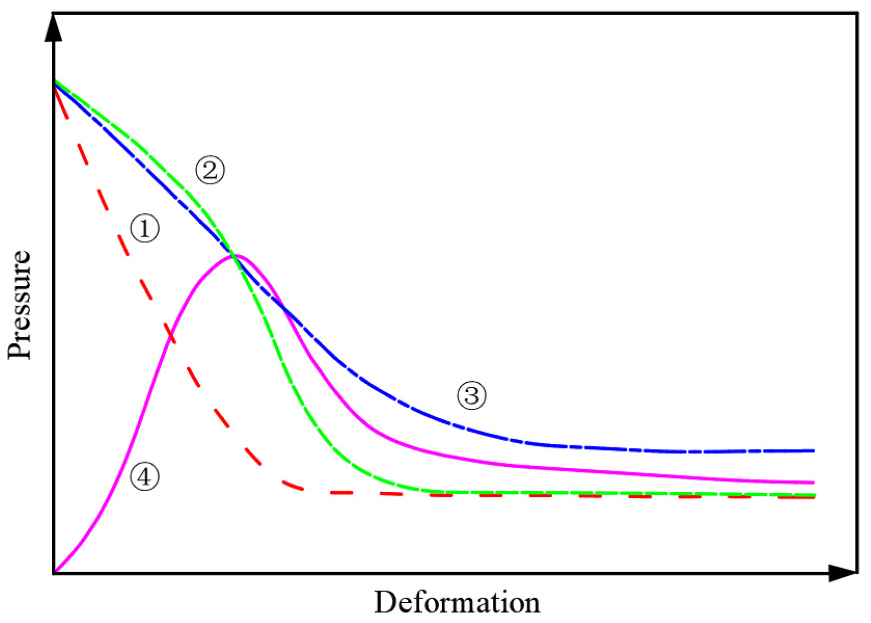
Equation (21) shows that the limit-equilibrium width
increases slowly but continuously with roadway depth H (
Figure 4). The coloured curves indicate different rock conditions: the red line represents a stable condition (e.g.,
= 0.8 MPa,
= 30°, A = 0.6), the green line a moderately stable condition (e.g.,
= 0.5 MPa,
= 25°, A = 0.6), and the blue line an unstable condition (e.g.,
= 0.3 MPa,
= 16°, A = 0.4). These interface cohesion and friction values fall within the range reported from laboratory direct shear tests on coal-rock interfaces, which supports the choice of parameters [
25].
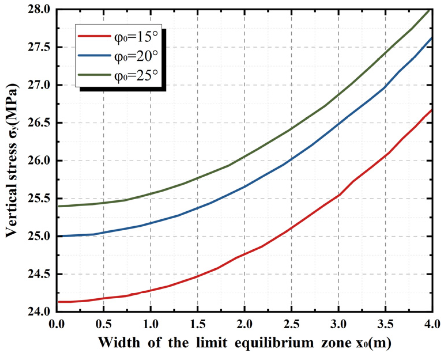
Increasing the friction angle
raises the shear strength of the coal-rock interface but decreases
. For example, when
, the calculated
is
. Vertical-stress distributions for various
values, obtained from Equation (8), are plotted in
Figure 5.
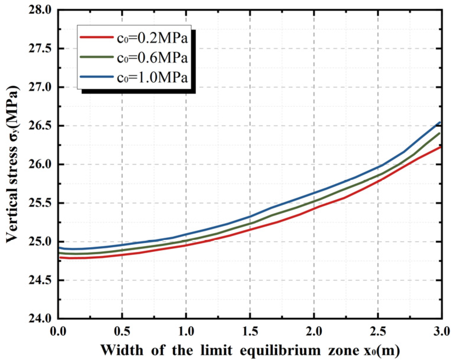
A higher cohesion
likewise raises
yet reduces
(
Figure 6).
A greater roadway height
enlarges
(
Figure 7), indicating that higher entries develop wider plastic zones under otherwise identical conditions.
The inward displacement of the coal rib is proportional to the lateral-pressure coefficient A and stress-concentration factor k, and inversely proportional to the composite elastic modulus E.
The limit-equilibrium width depends on roadway depth H, overburden unit weight , interface strength parameters (, , ), stress-concentration factor k, lateral-pressure coefficient A, roadway height m, and elastic modulus E. Specifically, decreases with increasing and but increases with H and m.
When exceeds the anchorage length of bolts and cables, rib deformation manifests mainly as pronounced inward movement, yet bolt/cable failure is rare. Conversely, if is shorter than the anchorage length and the lateral pressure exceeds the shear resistance of the reinforcement, splitting of the rib and shearing of bolts/cables can occur. If the lateral load is lower, the rib remains stable. Existing bolt-only support is not sufficient to restrain severe rib spalling; thus cable bolts longer than 4 m are required to control large deformations effectively.
4. Materials and Experimental Programme
4.1. Concrete-Mix Design Tests
The purpose of the mix design and compressive strength testing is to ensure that the chosen backfill material (C40 concrete) possesses sufficient mechanical strength to serve as a reliable roadside support, thereby underpinning the stability of the retained roadway.
The cement used was ordinary Portland cement (OPC) with a grade of 42.5 MPa, ensuring the potential to reach the C40 strength class. The fine aggregate was a well-graded medium river sand (fineness modulus 2.6–3.0), and the coarse aggregate was a crushed stone of 5–20 mm size. Both aggregates were clean (low fine content) and continuously graded, which helps improve the concrete’s workability and density. The mixed water was clean (settled and filtered mine water). A polycarboxylate-based high-range water-reducing admixture was added to enhance workability and pumpability without increasing the water content. This admixture was specifically chosen for its effectiveness in pumped concrete applications.
Workability was assessed by slump and slump-flow tests on a purpose-built platform (
Figure 8). An L9 orthogonal experimental design was adopted, varying four factors—mixing water, water-to-cement (w/c) ratio, coarse-aggregate fraction, and powder fraction—each at three levels (
Table 3). Factor ranges were established in accordance with mix-design guidelines and existing research [
26,
27]. Specifically, w/c ratios from 0.45 to 0.50 were examined. Although C40 concrete conventionally requires w/c ≤ 0.45 for strength, ratios up to 0.50 were included to secure pumpable workability. Water contents of 180–200 kg were selected to achieve a target slump of 230–250 mm, while coarse-aggregate and powder proportions were set at 0.50–0.60 and 0.45–0.50, respectively, to cover practical limits that ensure adequate flow without segregation. This orthogonal matrix facilitates systematic evaluation of each parameter’s influence on workability and compressive strength.
Range and variance analyses (
Table 4) identified the most influential factors.
Considering the above factors, the recommended proportions are: water 225 kg/m3, w/c 0.45, cement 500 kg/m3, coarse-aggregate ratio 0.60, sand-in-mortar ratio 0.45.
Field aggregates contain variable moisture, so the laboratory mix was adjusted for site conditions. Underground pumping trials confirmed acceptable workability. Field pumping trials with this mix were conducted in a borehole at the site, confirming its adequate workability for underground placement. The mix’s measured slump (230–250 mm) ensured it could be pumped over the required distance without segregation. The final C40 construction mix is shown in
Table 5.
4.2. Compressive-Strength Test of Concrete
Concrete cubes (150 mm × 150 mm × 150 mm) were cast in accordance with the Standard Test Methods for Concrete, with three specimens per batch. Moulds were coated with release agent, filled with concrete mixed to the target proportions, and struck off after slump measurement. After 24 h the specimens were demoulded, labelled, and cured at ambient temperature until the designated ages. They were then tested for compressive strength at an accredited laboratory, yielding complete strength–age curves. This strength satisfies the design criteria for the backfill (≥40 MPa at 28 days for C40 grade), indicating that the concrete wall will have the capacity to withstand the anticipated loads from the surrounding rock. In later sections, this chosen material strength directly contributes to the excellent stability observed in the field.
4.3. Stability Analysis of the Roadside Concrete Wall
A flexible-formwork concrete wall serves as the primary support along the gob-side entry. Failure occurs when the applied stress reaches the wall’s ultimate capacity or deformation exceeds the allowable limit, similar to rock failure under uniaxial compression. As mentioned in
Figure 9, typical modes include (i) shear failure, (ii) longitudinal splitting, (iii) failure along weak planes or faults, and (iv) bulging after the wall is forced into the floor.
As illustrated in
Figure 10, the concrete wall can operate in three distinct states. In the stable state, applied loads remain below the wall’s ultimate capacity and no visible damage develops. In the partially failed yet stable state, some local failure (e.g., minor cracking or spalling of the concrete wall) has occurred. However, the support structure continues to carry the load with a sufficient margin of safety. In this state, the wall and bolts have yielded only locally, and their applied loads remain below the residual strength capacity—in other words, the support’s factor of safety is still above 1.0—so the overall structure remains stable and intact. In the progressive failure state, either sustained loading or significant strength degradation reduces the residual capacity below the applied support pressure, causing failure to propagate until collapse. For practical roadway support, the design goal is to keep the wall within the second state, permitting limited plastic deformation while retaining adequate residual strength.
Wall stability depends mainly on load magnitude and geometry. A larger width-to-height ratio places the wall core under triaxial compression, markedly improving compressive resistance. Accordingly, both the expected load and wall dimensions must be optimised to ensure stability during mining-induced disturbance.
6. Field Application
6.1. Deep-Hole Directional Presplitting
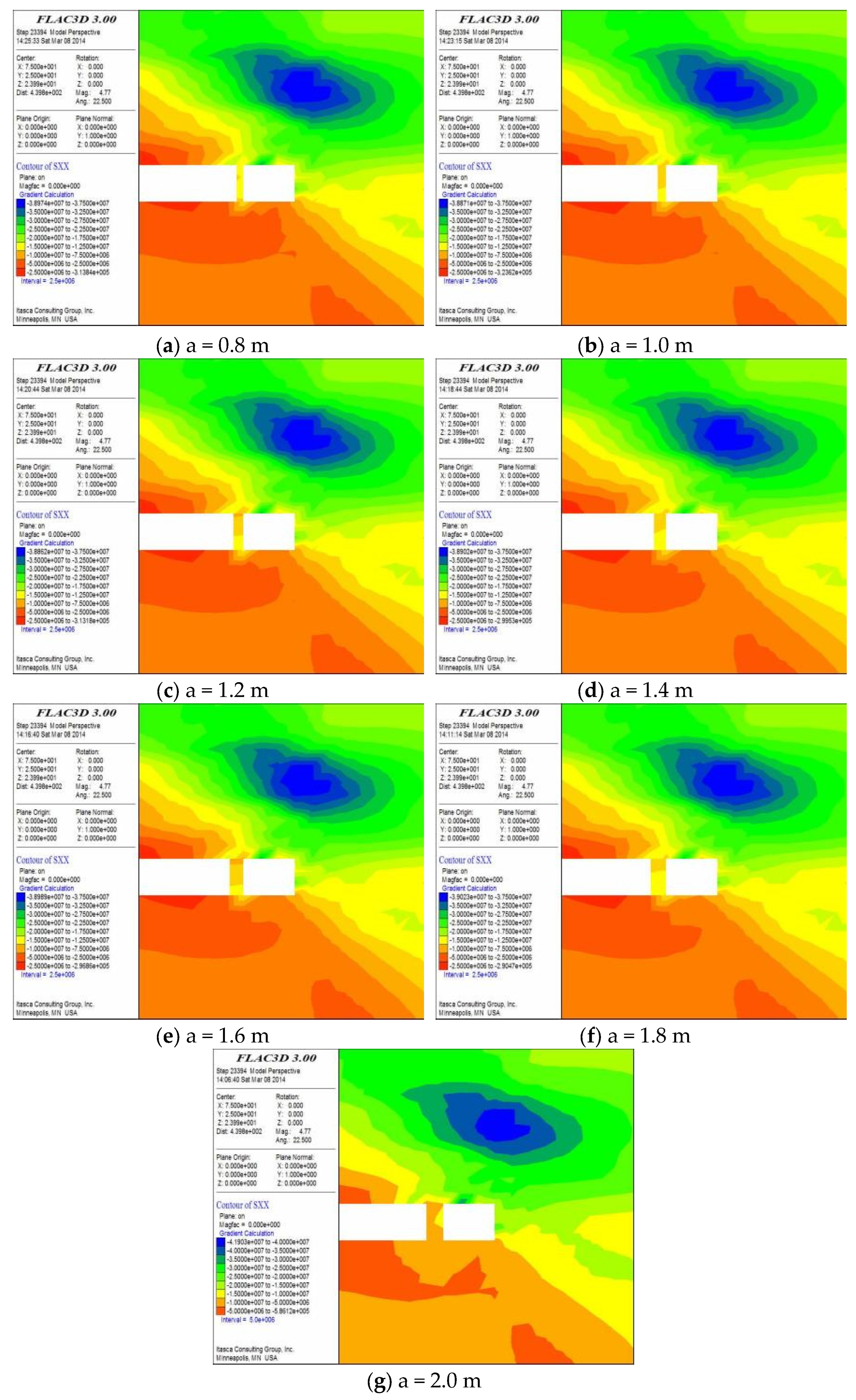
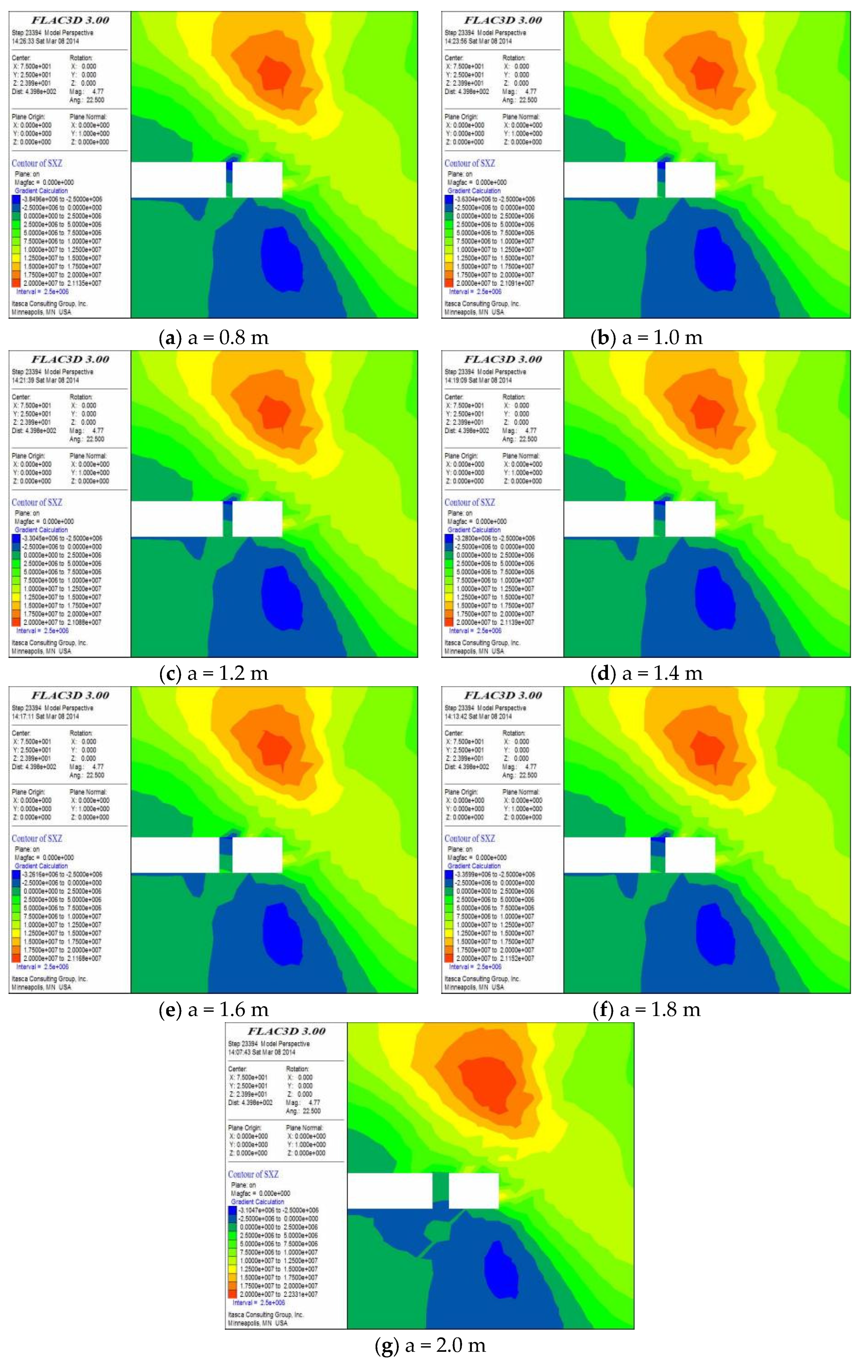
Prior to gob-side entry retaining in the auxiliary intake airway of Panel 3118, the roof was pre-split by deep-hole directional blasting. Optimised drilling parameters were: 60 mm borehole diameter, 75° inclination, 18 m hole length, 0.8 m spacing, 12 m charged section (6 m stemming), and 12 kg explosive per hole (
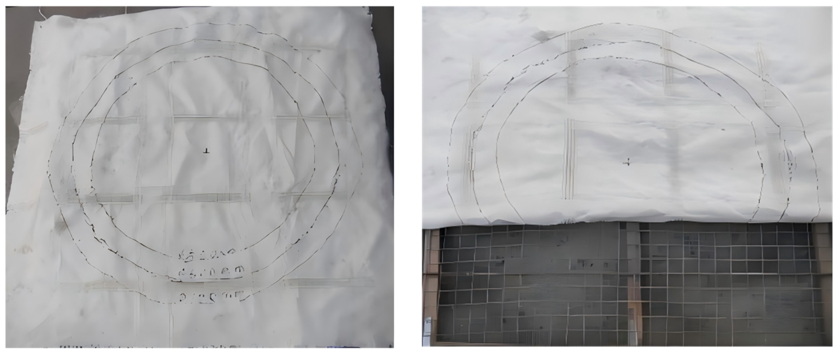
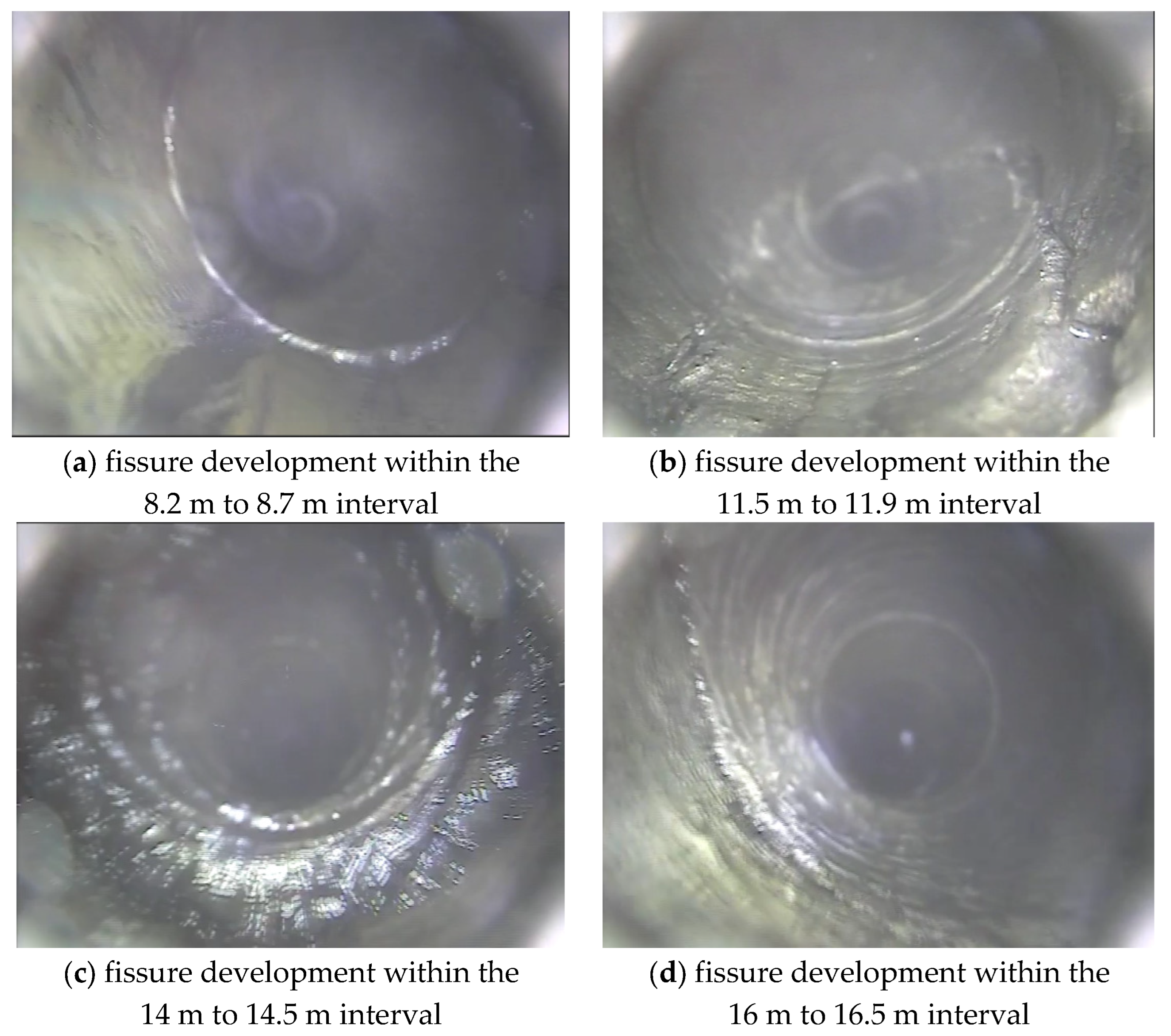
Table 7). Emulsion explosives and “O-shaped” energy-concentrating tubes were used to achieve bidirectional focused blasting. After drilling, a borehole camera was employed to inspect fractures in the roof (
Figure 19). Continuous cracks were observed from the bottom of the charged section to the hole collar, specifically at depths of 6.8–9.5 m, 11–13.8 m, 14–15.5 m, and 16–17.8 m; the cumulative crack length exceeded 70% of the blast section. The presplitting effectively weakened the roof, created a through-going fracture zone, and released mining-induced stress in advance. No significant roof damage or support failure was detected after blasting, indicating that the technique achieved its stress-relief objective without compromising surrounding support and thus provided a sound basis for subsequent safe entry retaining.
6.2. Anchor–Mesh–Cable Composite Support
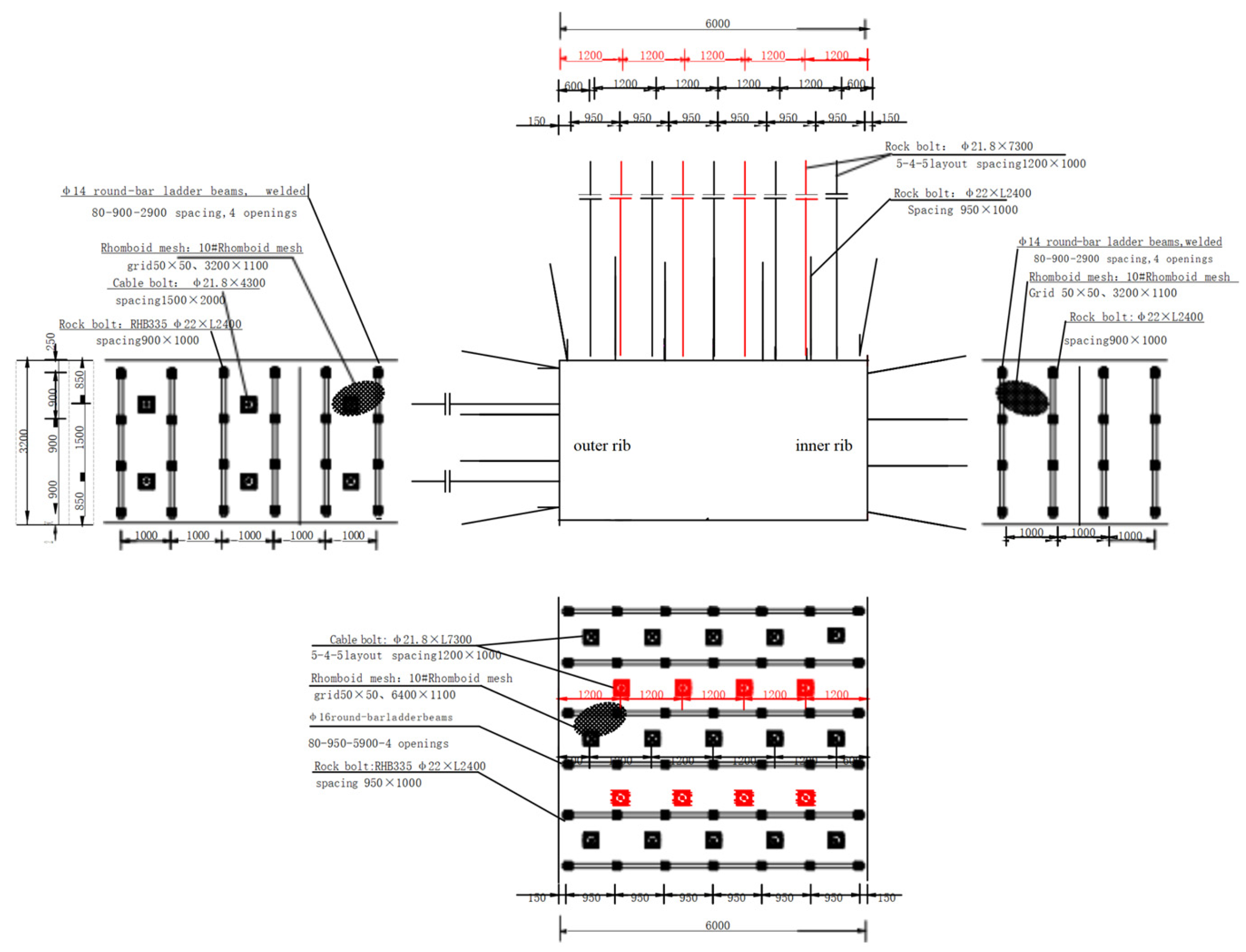
An anchor–mesh–cable support system was installed along the retained entries—namely, the Panel 3118 auxiliary intake airway and the Panel 3121 return roadway (see
Figure 20).
RHB335 rebar bolts (∅22 mm × 2 400 mm) were installed at a spacing of 0.95 m × 1.00 m and pretensioned to 300 N·m, meeting the required anchorage capacity. Roof cables consisted of ∅21.8 mm × 7 300 mm high-strength prestressed strands arranged in a 5-4-5 pattern at 1.20 m × 1.00 m spacing. Each cable was fitted with a 300 mm × 300 mm × 16 mm domed bearing plate and anchored with three resin cartridges (one CK2335 and two Z2360), providing an initial pretension of ≥250 kN.
Opposing-pair anchors (
Figure 21) were installed through the backfill wall: RHB500 left-hand threaded bars, ∅22 mm × 1 750 mm (for a wall thickness of 1500 mm), with thread lengths ≥150 mm on both ends, spaced at 0.80 m × 0.60 m and pretensioned to 300 N·m.
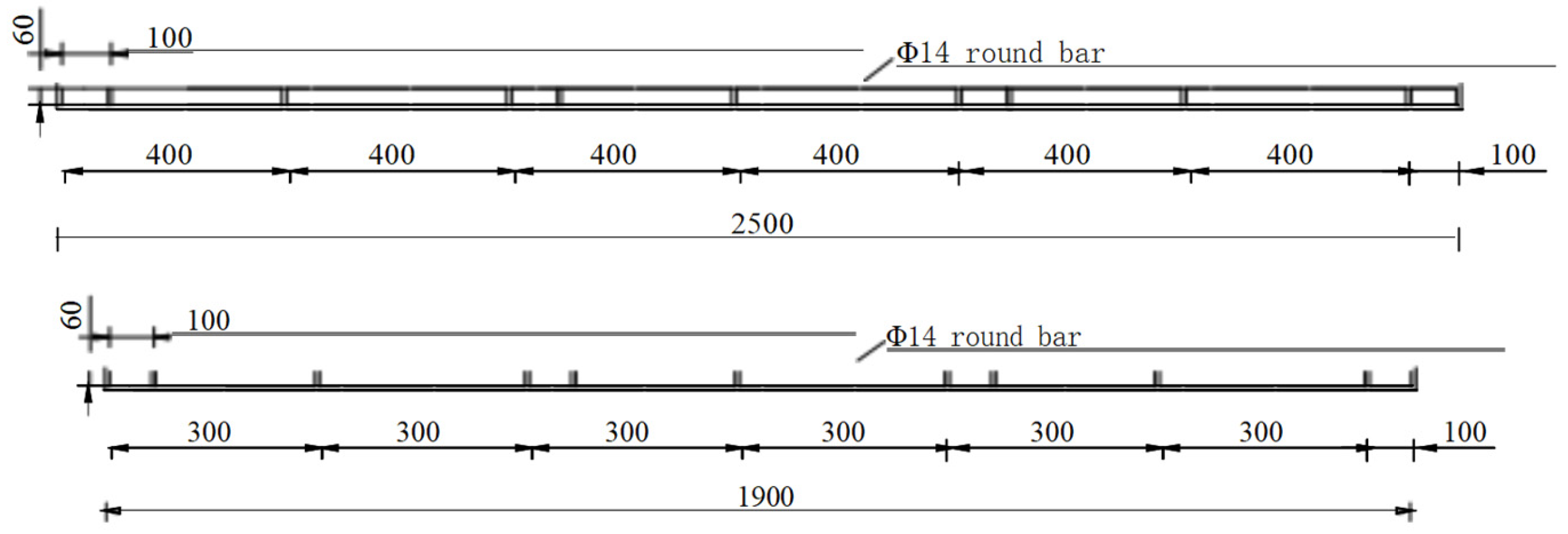
A ladder-shaped reinforcing beam was welded to connect upper and lower anchors (
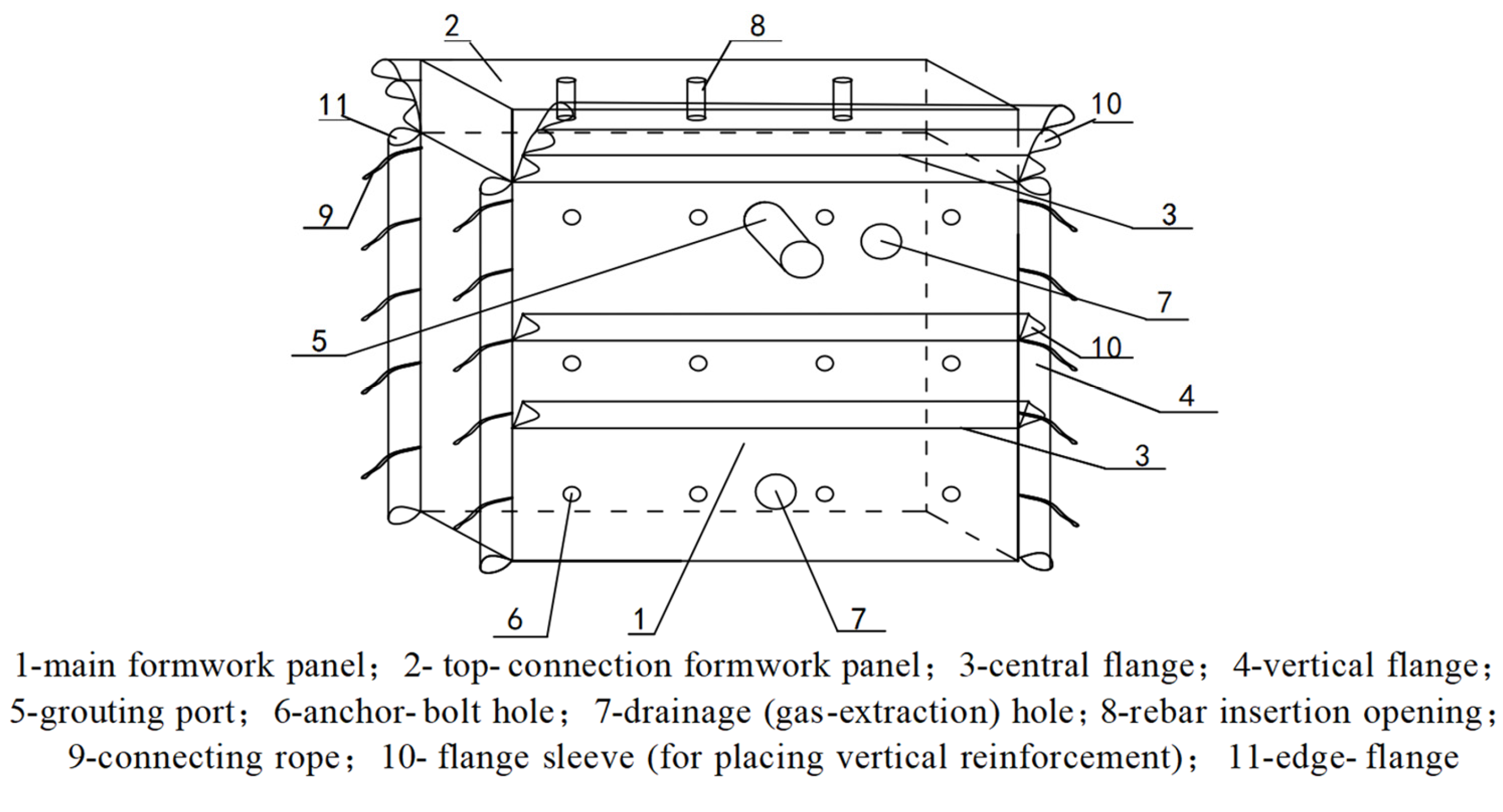
Figure 22), enhancing global stiffness. On the gob side of the entry, a three-dimensional flexible textile form (2400 mm × 1500 mm × 3500 mm;
Figure 23) was erected and filled with C40 concrete, creating a rigid retaining wall. The lightweight, high-strength formwork simplifies construction and isolates the goaf roof effectively. Both ribs were additionally covered with wire mesh and arched steel plates to prevent spalling.
These measures establish a “three-line defence”: bolts and mesh form the first layer of support around the entry perimeter; roof cables provide the second layer by reinforcing the immediate roof; and the concrete backfill wall supplies a rigid third barrier that isolates the goaf. Field operation shows this composite system has ample bearing capacity, effectively transmits mining-induced loads, and prevents large-scale roof collapse. Monitoring data reveal virtually no damage to bolts, cables, or the backfill wall, confirming that the anchor–mesh–cable arrangement greatly enhances the stability of the retained entry.
6.3. Monitoring and Analysis of Surrounding-Rock Deformation
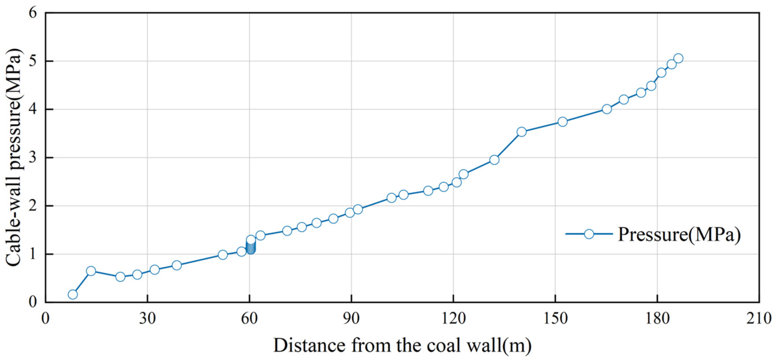
During retreat, an array of instruments was installed along the retained entry to record roadway convergence, roof-cable load, and wall pressure in real time. The data (
Figure 24,
Figure 25 and
Figure 26) reveal a staged deformation pattern. When the face lay 20–50 m from an instrument station, deformation accelerated; additional roof-to-floor convergence in this zone accounted for roughly half of the total closure. As the face advanced to within 50–100 m, convergence continued to rise—floor heave in particular increased rapidly from 75 mm to 160 mm. The cumulative closure reached about 340 mm, of which floor uplift contributed ≈65% (
Figure 24). Both ribs bowed inward by roughly 60 mm, whereas roof subsidence remained comparatively small, underscoring that floor heave is the principal factor governing roadway stability.
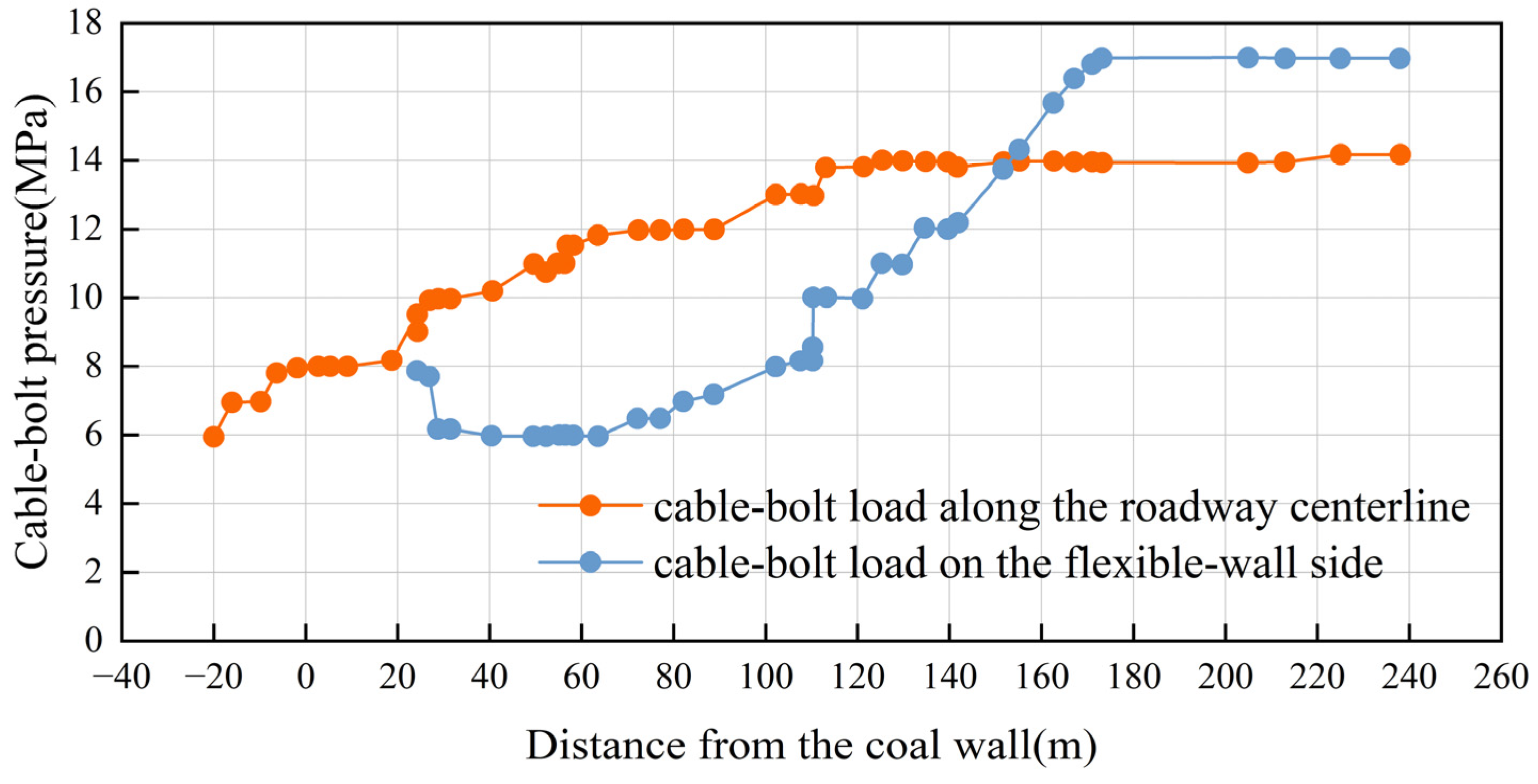
Roof-cable loads evolved with mining (
Figure 25). Along the roadway centre-line they rose gradually from 6 MPa at 20 m ahead of the face to 14 MPa at 120 m behind, then levelled off. On the gob-side, cable load jumped to a peak of 17 MPa at a 120 m lag before stabilising, indicating that release of early deformation increases cable demand—especially where the overhanging roof beam effect is strongest. Wall-pressure monitoring (
Figure 26) shows that after casting, pressure climbed rapidly to an initial peak of 0.65 MPa at 25 m lag, fell slightly to 0.53 MPa as the roof first fractured, and then rose again to about 5.05 MPa between 40 m and 200 m lag, corresponding to the first strong dynamic loading of the face. These observations confirm that the concrete wall carries most of the roof load at critical moments, while the adjacent cables delay deformation of the surrounding rock.
Overall, field monitoring verifies the effectiveness of the support design: the roadway remained within controllable limits and no support failures occurred. Deformation values and support loads stayed within acceptable ranges, demonstrating that the composite support system, combined with pre-splitting, effectively mitigates mining-induced impacts and ensures the long-term stability of the gob-side entry. Additionally, all recorded support loads remained within allowable limits. For example, the flexible concrete wall’s peak pressure of 5.05 MPa was well below its compressive capacity, and the maximum cable load of 17 MPa remained under the yield threshold, providing quantitative confirmation that the support system had sufficient capacity in line with theoretical and simulation predictions.
6.4. Performance Assessment
To rigorously evaluate the effectiveness of the proposed three-line defence system, a comparison was performed between numerical simulation results and actual field monitoring data. Numerical analyses indicated significant reductions in roadway stress and deformation when utilising the combined approach. Specifically, the simulations showed that omitting the concrete backfill wall resulted in peak vertical stresses in the coal rib of approximately 22.4 MPa. In contrast, incorporating the backfill wall reduced this peak to around 13.1 MPa. Field monitoring further corroborated these findings, recording roadway convergence of approximately 340 mm, substantially less than the >500 mm typically observed with conventional supports in deep coal mining conditions [
28]. The results indicate that this integrated support scheme suppresses roadway convergence by more than 30% compared with conventional techniques. Numerical results combined with field data indicate that the concrete backfill wall effectively absorbs residual stress from adjacent mined-out areas, thereby maintaining roadway stability. Consequently, each element of the three-line defence functions synergistically, significantly outperforming single-component support strategies in controlling roadway stability.
Furthermore, the proposed approach also exhibits clear advantages in cost-effectiveness, performance, and construction efficiency compared to traditional support methods such as high-water materials or U-shaped steel arches. Economically, flexible-formwork concrete walls, primarily utilising industrial waste such as coal gangue, have a unit cost of approximately ¥11,825 per linear metre (as detailed in
Table 8). This figure is significantly lower than traditional pillar-retention methods. In terms of material expenses, using waste gangue as aggregate in the concrete mix reduces the cost by nearly 50% compared to proprietary high-water filling materials, making the solution more economical. In terms of structural performance, flexible-formwork concrete provides robust residual strength and substantial deformation capacity under high-pressure conditions, thereby offering reliable initial support and long-term stability. In contrast, a conventional narrow coal pillar or an unsupported gob-side typically cannot sustain high-pressure conditions and would result in larger deformation. The internal bolt-mesh-cable support ensured that the immediate roof and coal ribs remained intact, unlike traditional wooden or U-steel supports, which might buckle or lose effectiveness as the roof deforms. Constructability is also improved. The flexible formwork concrete approach allows rapid installation by pumping concrete and using a collapsible formwork bag, enabling construction to keep pace with face advancement. This mechanised process is safer and faster than manually erecting U-shaped steel supports or building pack walls, and it forms a continuous, sealed structure that enhances ventilation and fire prevention.
Overall, compared to existing techniques, the proposed method offers a more cost-effective, higher-performance, and more easily implementable solution for gob-side entry retention in deep mines.

