Article

Performance Evaluation of a Sustainable Glulam Timber Rubrail and Noise Wall System Under MASH TL-3 Crash Conditions

by
Tewodros Y. Yosef
1,2,*,
Ronald K. Faller
1,2,
Qusai A. Alomari
1,2,
Jennifer D. Schmidt
3 and
Mojtaba Atash Bahar
1,2
1
Midwest Roadside Safety Facility, 151 Prem S. Paul Research Center at Whittier School, University of Nebraska-Lincoln, 2200 Vine St., Lincoln, NE 68583-0861, USA
2
Department of Civil and Environmental Engineering, 151 Prem S. Paul Research Center at Whittier School, University of Nebraska-Lincoln, 2200 Vine St., Lincoln, NE 68583-0861, USA
3
Safe Roads Research and Development, Stouffville, ON L4A 2G8, Canada
*
Author to whom correspondence should be addressed.
Infrastructures 2025, 10(9), 226; https://doi.org/10.3390/infrastructures10090226
Submission received: 15 July 2025 / Revised: 19 August 2025 / Accepted: 22 August 2025 / Published: 26 August 2025

Abstract

Noise barriers are commonly used to reduce the adverse effects of traffic noise in both urban and suburban settings. While conventional systems constructed from concrete and steel provide reliable acoustic and structural performance, they raise sustainability concerns due to high embodied energy and carbon emissions. Glued-laminated (glulam) timber has emerged as a sustainable alternative, offering a reduced carbon footprint, aesthetic appeal, and effective acoustic performance. However, the crashworthiness of timber-based noise wall systems remains under investigated, particularly with respect to the safety criteria established in the 2016 edition of the American Association of State Highway and Transportation Officials (AASHTO) Manual for Assessing Safety Hardware (MASH). This study presents the full-scale crash testing and evaluation of glulam rubrail and noise wall systems under MASH Test Level 3 (TL-3) impact conditions. Building on a previously tested system compliant with National Cooperative Highway Research Program (NCHRP) Report 350, modifications were made to increase rubrail dimensions to meet higher lateral design loads. Three full-scale vehicle crash tests were conducted using 1100C and 2270P vehicles at 100 km/h and 25 degrees, covering both front- and back-mounted wall configurations. All tested systems demonstrated acceptable structural performance, effective vehicle redirection, and compliance with MASH 2016 occupant risk criteria. There was no penetration or potential for debris intrusion into the occupant compartment, and all measured occupant risk values remained well below allowable thresholds. Minimal damage to structural components was observed. The results confirm that the modified glulam noise wall system meets current impact safety standards and is suitable for use along high-speed roadways. This work supports the integration of sustainable materials into roadside safety infrastructure without compromising crash performance.

1. Introduction

The rapid expansion of transportation networks and high-speed mobility corridors has significantly enhanced connectivity and efficiency in urban environments. However, this development has also intensified concerns related to traffic noise pollution, which poses substantial public health and environmental challenges. Prolonged exposure to elevated noise levels has been linked to adverse health outcomes, such as hypertension, tinnitus, and sleep disturbances [1,2]. To mitigate the harmful effects of traffic noise, researchers and engineers have investigated various abatement strategies, among which noise barriers remain one of the most widely adopted solutions. These structures are typically installed parallel to the roadway to shield adjacent communities from vehicle-generated noise [3].
Noise barriers, as an essential element of transportation infrastructure, are especially common in densely populated urban regions where noise exposure limits are often surpassed. Traditionally fabricated using reinforced concrete and steel, these systems have exhibited satisfactory acoustic and structural performance. Nonetheless, their creation and lifecycle lead to environmental degradation due to resource-intensive manufacturing methods, increased embodied carbon emissions, and substantial energy usage [4,5]. Due to rising demands for sustainable construction practices, there is an increased interest in employing renewable materials, such as glued-laminated (glulam) timber in infrastructure applications. Glulam demonstrates advantageous acoustic properties, harmoniously integrates with natural environments, and has a significantly reduced carbon footprint, positioning it as a viable option for environmentally sustainable infrastructure development [6,7].
While the primary design objective of noise barriers is acoustic attenuation, their close proximity to traffic lanes introduces the need to evaluate their performance under vehicular impact conditions. One proposed solution to mitigate collision risks is to place noise walls beyond the roadside clear zone, as recommended by the American Association of State Highway and Transportation Officials Load and Resistance Factor Design (AASHTO LRFD) Bridge Design Specifications [8]. However, such placement is frequently constrained by spatial limitations and high land acquisition costs. Consequently, noise wall systems installed within the clear zone must be designed not only for acoustic effectiveness but also for impact safety. Barriers that are not designed to safely contain or redirect errant vehicles pose significant hazards, increasing the potential for secondary crash events.
To address these safety concerns, the AASHTO Manual for Assessing Safety Hardware (MASH) provides standardized impact performance criteria for longitudinal barriers, encompassing structural adequacy, occupant risk, and post-impact vehicle trajectory behavior [9]. While steel and concrete systems have been extensively tested under MASH guidelines, the impact behavior of timber-based noise wall systems remains largely unexplored. This gap is of particular concern given the anisotropic mechanical behavior of timber, its strain-rate sensitivity, and the possibility of brittle or splintering failure modes under dynamic loading [10]. Without rigorous experimental validation, timber systems may be disqualified from use in safety-critical roadside installations, despite their sustainability benefits. Accordingly, performance-based assessments are essential to ensure that timber noise walls meet both environmental objectives and modern impact safety requirements.
Currently, only a few noise wall systems have been evaluated for crashworthiness, typically for Test Level 3 (TL-3) through Test Level 5 (TL-5) scenarios. For example, in 2001, researchers from the Texas Department of Transportation (DOT) and Texas A&M Transportation Institute (TTI) developed a crashworthy noise wall integrated with a modified Texas T501 bridge railing. The system was tested in accordance with TL-4 criteria from National Cooperative Highway Research Program (NCHRP) Report 350, using full-scale vehicle crash tests involving a 2000P pickup truck and an 8000S single-unit truck [11,12]. The Texas DOT noise barrier system is shown in Figure 1a.
In another effort, researchers at the Midwest Roadside Safety Facility (MwRSF) developed a transparent noise wall system in collaboration with CYRO Industries [13,14] (Figure 1b). Designed for use on single-slope concrete barriers and incorporating Paraglas Soundstop GS CC panels, the system was tested under NCHRP Report 350 TL-4 guidelines. Full-scale tests included an 8092 kg single-unit truck at 82.4 km/h and 17.7°, and a 2013 kg pickup truck at 99.0 km/h and 25.0°, as shown in Figure 1b.
In a third case, the Minnesota Department of Transportation (MnDOT) originally designed a concrete post and wood plank noise wall system for use in urban areas. In 2005, MnDOT and MwRSF collaborated to develop and crash test a version with a glue-laminated timber rubrail, intended for use in locations where the wall is placed within the clear zone and conventional safety devices are undesirable [15]. This system featured a 24.7 m long glulam timber rail supported by reinforced concrete posts. The rubrail, composed of 222 mm × 343 mm glulam timber sections, was anchored to the post faces and reinforced with cable connections to resist lateral vehicle impacts (Figure 1c). A 1989 kg pickup truck crash test conducted at 99.5 km/h and 25.3° confirmed compliance with TL-3 criteria under NCHRP Report 350. However, this system had not yet been evaluated according to the more stringent MASH 2016 guidelines.
Despite the widespread use of reinforced concrete and steel for roadside noise walls, there is a lack of experimental crash performance data for alternative materials, such as glulam timber. While glulam systems are recognized for their acoustic performance and environmental advantages, their crashworthiness under modern safety standards has not been validated through full-scale testing. This gap in knowledge limits the broader adoption of timber-based solutions in transportation infrastructure. The research problem addressed in this study is the absence of validated crash performance data for glulam timber noise wall and rubrail systems relative to MASH TL-3 impact safety requirements, and the need to determine whether such systems can provide safety performance comparable to conventional materials while offering reduced structural mass and embodied carbon. This study directly addresses this gap through full-scale crash testing and comparative evaluation.
The objectives of this study are threefold. First, to evaluate the crash performance of the MnDOT glulam timber rubrail and noise wall system under TL-3 impact conditions as specified in MASH 2016, using full-scale crash testing. Second, to compare the structural capacity and occupant safety performance of the glulam system with established impact safety criteria, thereby determining its compliance with relevant standards. To address the increased severity of impact scenarios introduced in MASH 2016, particularly for small car and pickup truck tests, design modifications were implemented to enhance impact resistance and reduce the potential for vehicle snagging. Two system configurations were assessed, as follows: (i) timber planks mounted on the rear face of the concrete posts and (ii) planks mounted on the traffic-facing front face. Third, we assessed the broader potential of glulam systems as sustainable roadside noise barriers, considering both crashworthiness and their environmental advantages relative to conventional concrete and steel alternatives.

2. Design and System Details

2.1. Design

MnDOT’s existing standard noise wall and rubrail system was originally designed and successfully tested in accordance with the NCHRP Report No. 350 test no. 3-11 impact conditions, as part of its roadside safety hardware portfolio. The rubrail was specified as a glulam wood rubrail fabricated with Combination no. 48 Southern Pine or Combination no. 2 Western Species material, with 222 mm depth and 343 mm height. However, the nominal impact severity associated with test designation 3-11 increased by 13.4%, rising from 137.6 kJ under NCHRP Report 350 to 156.1 kJ under MASH 2016. This increased impact severity can be directly attributed to the increased vehicle mass. Impact severity is defined as the kinetic energy of a vehicle at the moment of impact and is a function of both mass and velocity.
For the present study, the glulam rail members and spacer blocks were fabricated from Combination No. 2 West Coast Douglas Fir in accordance with the AASHTO LRFD Bridge Design Specifications [8]. Fabrication conformed to ANSI A190.1-2012 for structural glued laminated timber and was performed by Zip-O-Laminators, LLC under accreditation by the Engineered Wood Association (APA). The members were supplied by Western Wood Structures, and all glulam components were pressure-treated with pentachlorophenol in heavy oil to a minimum net retention of 9.6 kg/m3 to ensure durability in outdoor exposure.
The lateral design load for an NCHRP Report 350 TL-3 bridge rail was 240 kN applied over a 1.2 m length [8], which was also commonly used for other semi-rigid and rigid roadside barriers. Recently, the final report on NCHRP Project 22-20 [16] recommended a 311 kN load applied over a 1.2 m length for barrier design under MASH TL-3 [9]. With the increased impact severity and lateral impact load, the existing rubrail may not have sufficient structural capacity to resist 2270P pickup truck crashes under MASH test designation 3-11 conditions. Thus, research efforts were devoted to evaluating the structural capacity of the rubrail and redesigning the system before conducting the full-scale vehicle crash test.
While most of the design components were designed by MnDOT to meet their needs for a noise wall, the American Wood Council National Design Specification (NDS) for Wood Construction was utilized to evaluate the capacity of the glulam rubrail [17]. The allowable bending stress for use in design was 31.0 MPa and 27.9 MPa for Combination no. 48 Southern Pine and Combination no. 2 Western Species, respectively. Since the rubrail in the original crash test did not fail due to excessive bending stress, the design calculations were believed to be conservative. The same ratios of actual/allowable bending stress with the 240 kN lateral design load (1.256 for Combination no. 48 Southern Pine and 1.396 for Combination no. 2 Western Species) were utilized for analyzing and modifying the rubrail to meet the 311.4 kN lateral design load, which likely would not experience excessive bending stress in a MASH test designation 3-11 crash test.
A 254 mm deep by 343 mm tall rubrail was determined to produce similar ratios for actual/allowable bending stress and was anticipated to perform acceptably. However, a 254 mm deep beam was determined to be a non-standard size. Therefore, a 273 mm wide and 343 mm long rubrail, which is a standard glue-laminated size, was determined to produce a ratio for actual/allowable bending stress equal to 1.112 and 1.234 percent for the Combination no. 48 Southern Pine and Combination no. 2 Western Species, respectively. Since these two ratios were less than those found for the prior crash-tested rubrail, the research team believed that the new rubrail section in each species would also perform acceptably and not fail due to excessive bending stress. Therefore, a 273 mm deep by 343 mm tall, glulam wood rubrail, fabricated from Combination no. 48 Southern Pine or Combination no. 2 Western Species material, was recommended for use in the full-scale vehicle crash testing and evaluation program.

2.2. System Details

The noise wall and glulam timber rubrail barrier system was fabricated and constructed at the MwRSF outdoor testing site. As previously noted, two configurations were evaluated: one in which the wood noise wall planks were installed on the back side of the concrete posts (Tests MNNW-1 and MNNW-2), and another where the planks were installed on the front side of the concrete posts (Test MNNW-3).
MnDOT employs various post sizes, embedment depths, and wall heights to accommodate the differing noise wall requirements throughout the state. A glulam timber rubrail noise barrier system, designated MNTR-1, had been previously developed and successfully crash tested under the NCHRP Report No. 350 guidelines, satisfying TL-3 impact safety performance criteria.
For this study, the noise wall system height was selected to match the previously evaluated MNTR-1 configuration. The system included one of MnDOT’s smaller wall heights and embedment depths, while still offering significant stiffness and strength when embedded in soil. Based on prior testing experience, the selected configuration was considered to be representative of MnDOT’s broader design range.
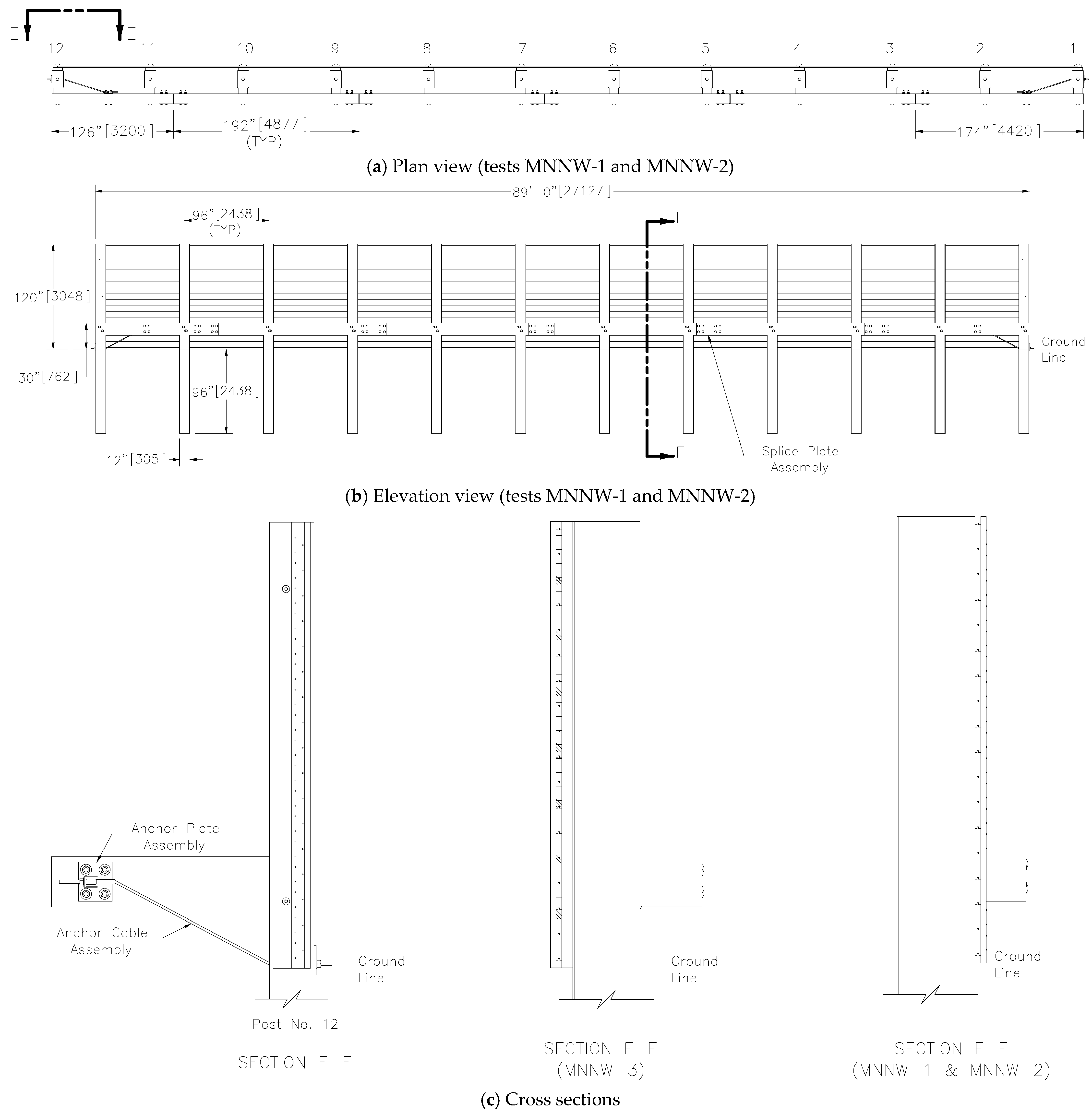
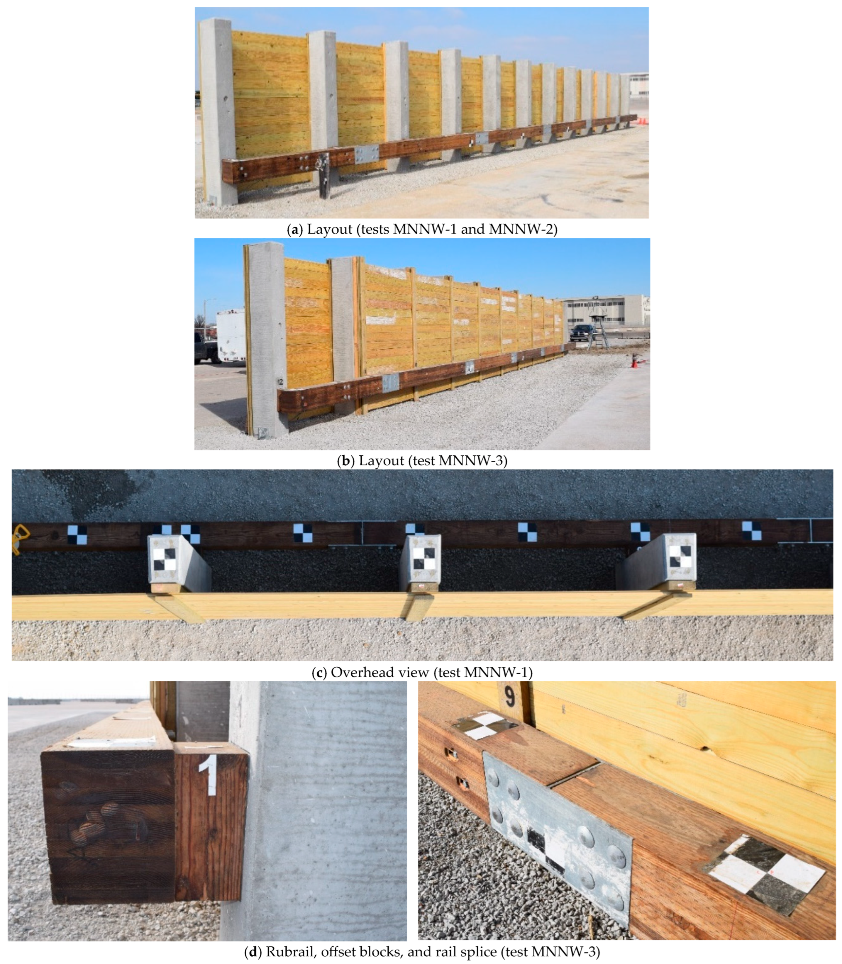
The test installation consisted of a wood plank noise wall supported by twelve vertical prestressed concrete support posts, shielded by a 27.13 m long glulam timber rubrail system. This rubrail was composed of six timber segments connected by five welded steel H-shaped splice plates, each 9.53 mm thick. Spacer blocks made of glulam timber, 229 mm wide by 152 mm deep by 343 mm long, were used to offset the rubrail from the front face of the posts. Each concrete post measured approximately 305 mm by 457 mm in cross section and 5486 mm in length. The posts were spaced 2438 mm apart from the center, with a soil embedment depth also of 2438 mm. The assembled noise wall and glulam timber rubrail system is illustrated in Figure 2 and Figure 3.

3. Test Requirements and Evaluation Criteria

To be considered eligible for federal reimbursement by the Federal Highway Administration (FHWA) for installation on the National Highway System (NHS), longitudinal barrier systems, such as integrated noise walls with glulam timber rubrails, must comply with impact performance standards. For newly developed roadside hardware, these standards are defined in the Manual for Assessing Safety Hardware (MASH 2016) [9]. Under Test Level 3 (TL-3) of MASH 2016, a barrier system is required to undergo two full-scale crash evaluations: (1) a 1100 kg passenger car (test designation 1100C) striking the barrier at 100 km/h (62 mph) and a 25° angle, and (2) a 2270 kg pickup truck (test designation 2270P) impacting under the same speed and angle conditions.
Crash test performance is judged according to the following three main factors: (1) structural adequacy, (2) occupant safety, and (3) post-impact vehicle trajectory. As outlined in MASH 2016 [9], structural adequacy assesses whether the barrier system can successfully contain and redirect vehicles while allowing limited lateral deflection. Occupant safety focuses on the potential risks of injury to individuals inside the striking vehicle. Finally, the evaluation of vehicle trajectory considers whether the post-impact path of the vehicle could lead to secondary crashes with nearby traffic or roadside objects, thereby posing further danger to the occupants of the impacting or surrounding vehicles.
In accordance with the MASH, occupant impact velocity (OIV) and occupant ridedown acceleration (ORA) are the two primary metrics used to evaluate occupant risk in crash safety analysis. These quantities are not measured directly from a physical occupancy model. Instead, they are derived from the vehicle’s dynamic response, assuming the motion of a hypothetical occupant inside the vehicle.
The OIV is computed as follows:
O I V   = 0 t * a   d t
where a is the vehicle acceleration in the relative direction, t is time, and t * is the time at which the hypothetical occupant reaches a relative displacement of 0.6 m in the longitudinal direction or 0.3 m in the lateral direction, whichever is smaller. This threshold is determined from the following:
0 t x 0 τ a x d t 2 = 0.6 ,   0 t y 0 τ a y d t 2 = 0.3
where a x and a y are the occupant accelerations in the longitudinal and lateral directions, respectively, and t * = m i n t x , t y , represents the smaller of the free motion times in two directions.
The ORA is calculated as the maximum average vehicle acceleration in any 10-millisecond window beginning at or after t*, as follows:
O R A t = 1 δ t t + δ a   d t   δ   = 10 ms ,   t t *
O R A = m a x O R A ( t )
In addition to the standard occupant risk criteria, three dynamic performance metrics were evaluated to characterize the severity of vehicular impact from the perspective of occupant biomechanics: the Theoretical Head Impact Velocity (THIV), the Post-Impact Head Deceleration (PHD), and the Acceleration Severity Index (ASI). These metrics, defined in MASH 2016, offer complementary insight into occupant kinematics and the potential for injury in crash events.
THIV quantifies the relative velocity between an unrestrained occupant’s head and the vehicle interior at the theoretical instant of impact, based on measured translational accelerations. Assuming a rigid occupant compartment and idealized motion, THIV is computed by integrating the vehicle’s acceleration vector twice over time, as follows:
T H I V = t 0 t 1 t 0 τ a ( t ) d t d τ
where a(t) is the resultant acceleration vector, t 0 is the initial time of impact, and t 1 corresponds to the theoretical moment of head contact. The THIV magnitude correlates with the likelihood of head contact injuries, with values below 33   k m / h (9.17 m/s) generally considered acceptable.
The PHD measures the peak deceleration experienced by the occupant’s head immediately following the theoretical impact moment. It reflects the severity of rebound effects and is extracted from the acceleration profile as follows:
P H D = m a x ( | a ( t ) | ) , t t 1 , t 2
where t 1 is the instant of theoretical head impact, and t 2 denotes the end of the rebound phase. Excessive PHD values are associated with potential for neck and spine injuries.
The ASI, a dimensionless parameter, quantifies the severity of translational accelerations in three orthogonal directions and is widely used in roadside safety evaluation. It is calculated as follows:
A S I t = a x ( t ) a x , l i m 2 + a y ( t ) a y , l i m 2 + a z ( t ) a z , l i m 2
where a x ( t ) , a y ( t ) , a z ( t ) are the vehicle accelerations in longitudinal, lateral, and vertical directions, respectively, and a x , l i m , a y , l i m , a z , l i m are the respective threshold values (typically 12   m / s 2 , 9   m / s 2 , and 10   m / s 2 . The maximum ASI value over the duration of the event is reported, with values below 1.0 indicating acceptable occupant risk.

4. Test Apparatus and Instrumentation

4.1. Vehicle Tow and Guidance System

A reverse-cable tow system with a 1:2 mechanical advantage was used to accelerate the test vehicles. In this setup, the tow vehicle traveled at half the speed and distance of the test vehicle. The cable was released before impact so that the test vehicle was moving independently at the moment of contact with the barrier. The tow vehicle was equipped with a digital speedometer to maintain accurate control of the target test speed.
Vehicle guidance was provided by the Hinch system [18], which directed the test vehicle along a pre-tensioned guide cable with a diameter of 9.5 mm. The cable was tensioned to about 15.6 kN and supported both vertically and laterally at 30.5 m intervals using hinged stanchions. A guide flag attached to the left front wheel engaged with the cable and detached just before impact, while the vehicle displaced each stanchion sequentially as it advanced along its path.

4.2. Test Vehicles

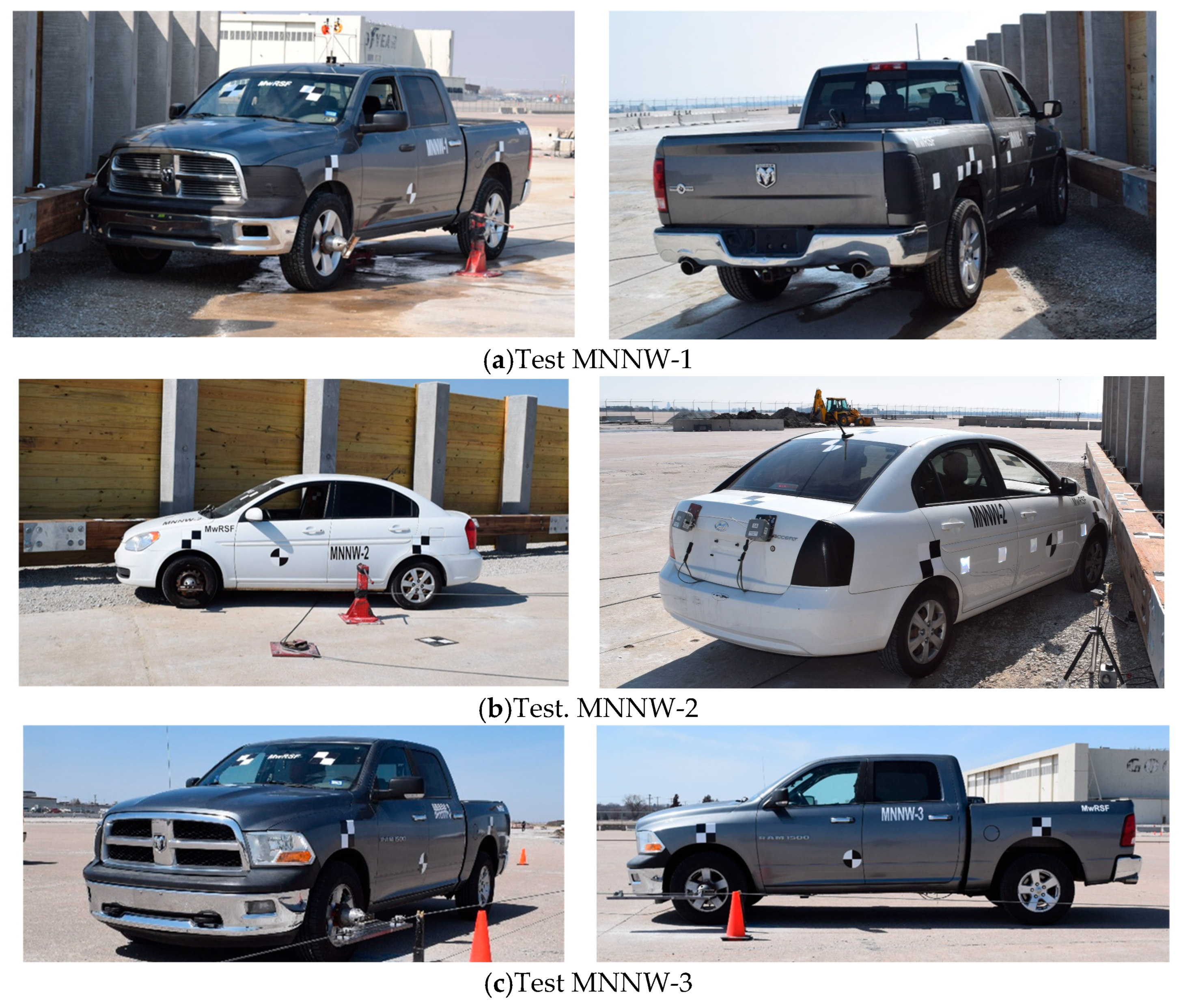
Three full-scale crash tests were conducted using vehicles representative of MASH TL-3 impact conditions. In accordance with MASH specifications, vehicle weights are reported in kilograms to represent inertial mass values used in crash testing. For test MNNW-1, a 2010 Dodge Ram 1500 Crew Cab pickup truck was utilized, with curb, inertial (ballasted and instrumented), and gross static (pre-impact) weights of 2388 kg, 2293 kg, and 2365 kg, respectively. Test MNNW-2 employed a 2010 Hyundai Accent with respective weights of 1123 kg, 1103 kg, and 1177 kg. Test MNNW-3 again used a Dodge Ram 1500 of the same model year, with respective weights of 2388 kg, 2281 kg, and 2353 kg.
The center of gravity (c.g.) was measured using the Suspension Method [19]. This method involves suspending the vehicle in three different positions and locating the intersection of the vertical planes passing through the suspension points. For the small car in test MNNW-2, the vertical c.g. position was obtained following the procedures outlined by SAE [20]. The test vehicles are presented in Figure 4.

4.3. Simulated Occupants

Each vehicle was equipped with a Hybrid II 50th-percentile adult male dummy (model 572, Android Systems, Carson, CA, USA) placed in the right front passenger seat. Dummies had final weights of 73 kg in all tests and were fitted with standard clothing and footwear. Seatbelts were fastened in accordance with MASH 2016 specifications. Dummy mass was excluded from the c.g. determination, as stipulated by the guidelines.

4.4. Data Acquisition and Instrumentation

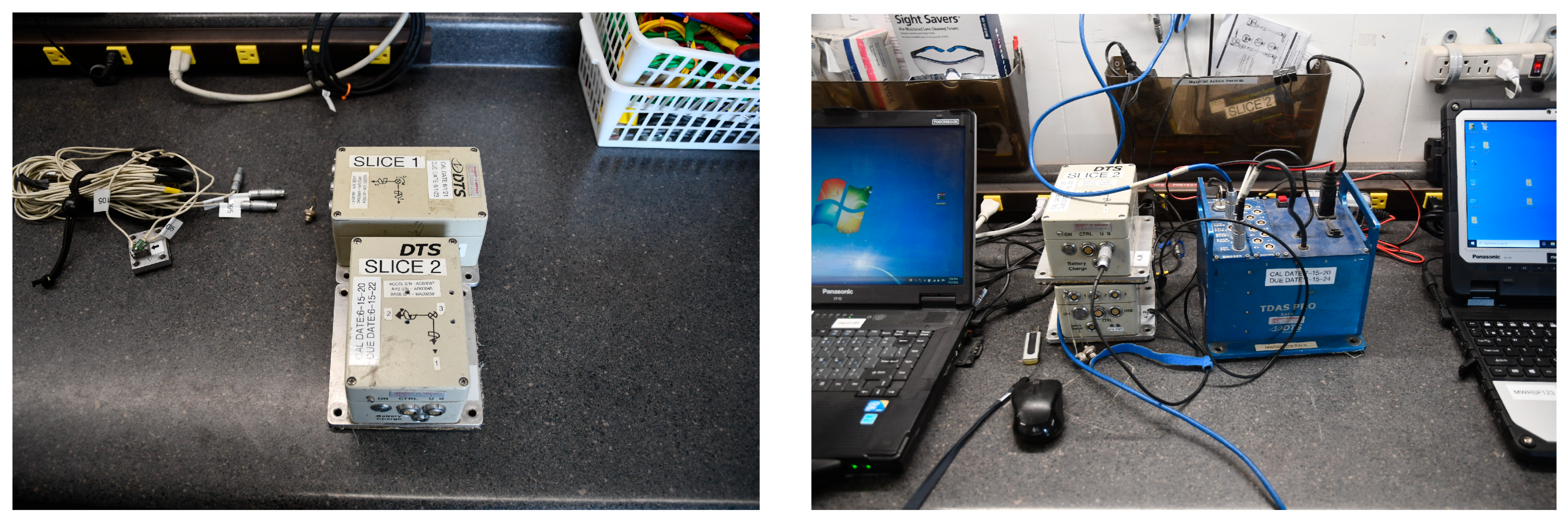
Triaxial acceleration data were collected using SLICE-1 and SLICE-2 systems manufactured by Diversified Technical Systems, Inc. These modular data acquisition units were installed near vehicle c.g., sampled at 10,000 Hz with a range of ±500 g, and were equipped with SAE Class 60 and Class 180 Butterworth filters in compliance with SAE J211/1 [21]. Data were stored in onboard memory and processed using SLICEWare software and custom Excel tools. Each SLICE unit also included a MICRO Triax ARS angular rate sensor, with a ±1500 deg/sec range for roll, pitch, and yaw. These sensors captured rotational kinematics at 10,000 Hz and were used to compute Euler angles for detailed vehicle motion analysis. A representative photograph of the SLICE-1 and SLICE-2 accelerometer packages is provided in Figure 5.
Vehicle speeds at impact were verified using a retroreflective optic speed trap system. Five retroreflective markers, spaced at 457 mm, were applied to the side of the vehicle. The system recorded beam interruptions at 10,000 Hz, enabling speed calculation based on marker spacing and time intervals. LED flashes and high-speed video served as redundant systems.
Test events were recorded using AOS high-speed digital video cameras, GoPro units, and JVC camcorders. Tests MNNW-1, MNNW-2, and MNNW-3 were captured using 17, 16, and 15 video sources, respectively. TEMA Motion and RedLake MotionScope software packages were used for motion tracking and post-processing, and a Nikon digital still camera was employed for pre- and post-test documentation. Each vehicle was fitted with a 5B flash bulb mounted to the right windshield wiper, triggered via a bumper-mounted pressure switch to indicate the exact moment of impact. A remote-controlled braking system allowed safe recovery of vehicles following test completion. Checkered square and round targets were applied to the vehicle sides and roofs for video tracking purposes.

5. Full-Scale Vehicle Crash Tests

Three full-scale crash tests were conducted in accordance with MASH TL-3 requirements. Test MNNW-1 followed the MASH 3-11 protocol with sound panels mounted on the backside of the barrier. Test MNNW-2 was performed under the MASH 3-10 protocol, also with backside-mounted sound panels. In contrast, Test MNNW-3 utilized the MASH 3-11 configuration but with sound panels affixed to the front face of the system. A separate test configuration involving MASH 3-10 with front-mounted panels was classified as non-critical, provided the other test conditions demonstrated satisfactory performance and comparable loading characteristics between front and back arrangements. The nominal test conditions, as prescribed by MASH TL-3, specified an impact speed of 100 km/hr and an angle of 25°.
Prior to each test, concrete posts were inspected for damage, dimensional compliance, and mechanical integrity. Soil backfill and compaction around each post location were restored to match initial test conditions, following a standardized compaction protocol to MASH specifications.

5.1. Test MNNW-1

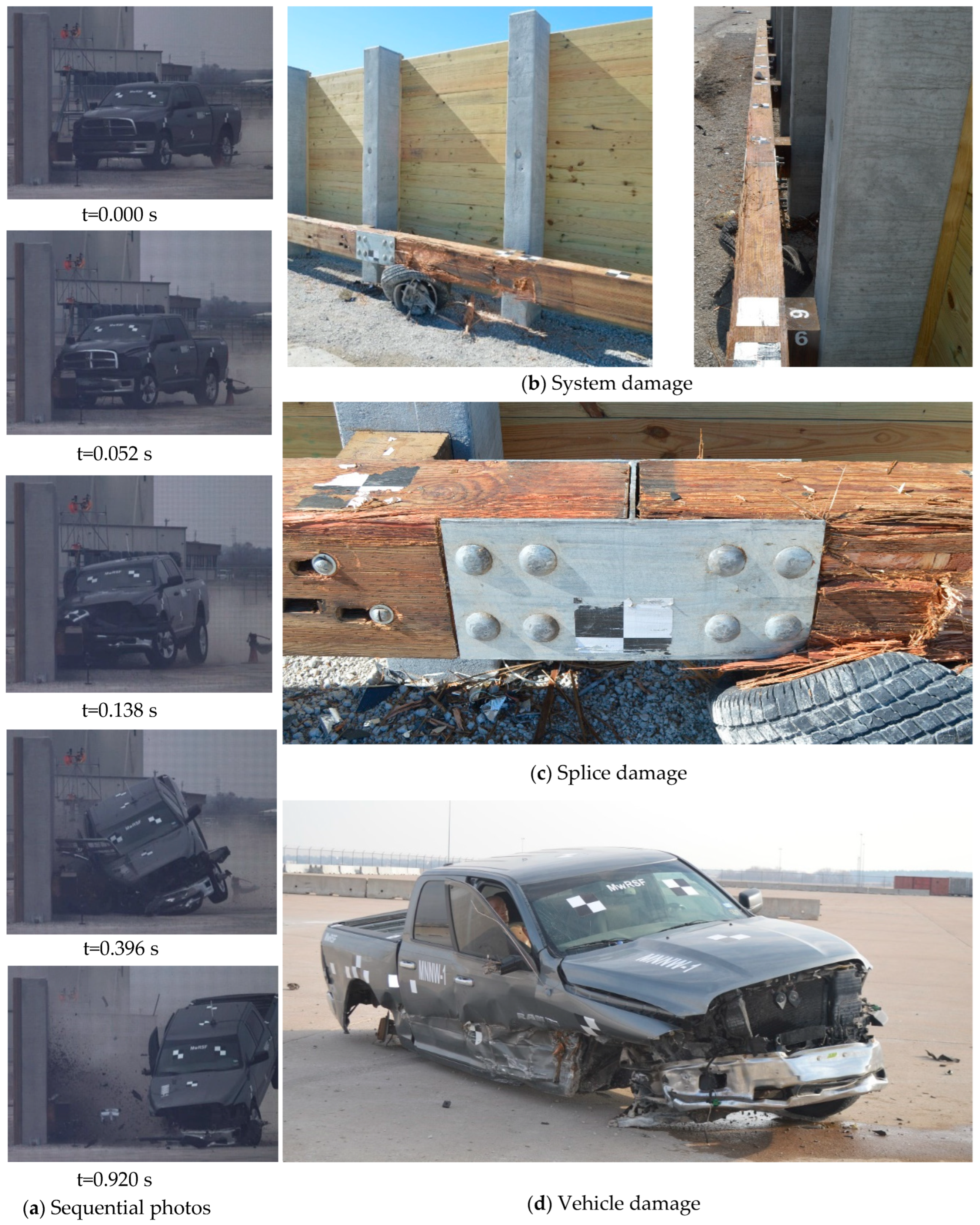
Test MNNW-1 involved a 2293 kg pickup truck impacting the noise wall system at 101.4 km/h and 24.7°. The intended impact location was 305 mm upstream from the centerline of post 6, a position selected to increase the vehicle’s extent behind the barrier and elevate snagging potential on the concrete posts [15]. The actual point of contact was 11 mm downstream from the target location.
Damage to the barrier was minimal and consisted of gouging, contact marks, and localized splintering of the timber rub rail (Figure 6), particularly around posts 5, 6, and 7 where the primary impact occurred. No structural damage was observed in the concrete posts or the sound wall. The maximum lateral permanent deformation of the barrier system was measured at 22 mm at midspan between posts 6 and 7. Post displacements at rail height reached 6.35 mm. The peak dynamic lateral deflection, obtained through high-speed digital video analysis, was 96.52 mm at the top of post 7.
Vehicle damage was moderate and concentrated along the right front corner and side. All MASH 2016 occupant compartment deformation thresholds were satisfied. The highest deformation measured within the compartment was 165.1 mm, located at the right front side panel.

5.2. Test MNNW-2

In Test MNNW-2, a 1103 kg small car impacted the barrier at 101.5 km/h and an angle of 25.4°. The designated impact point was located 1100 mm upstream of the splice between posts 6 and 7, in accordance with MASH Table 2.7, to increase the potential for wheel snag. The actual contact point occurred approximately 73 mm upstream of this target.
The barrier sustained only minor damage (Figure 7), including front face contact marks, gouging along the timber rail, and rotational displacement of a spacer block. The maximum permanent set was limited to 3 mm, observed at two locations: at rail height near post 7 and at midspan between posts 5 and 6. The dynamic lateral deflection reached 114.3 mm at the top of post 7, as determined through high-speed video analysis.
Vehicle deformation was moderate and confined to the right front region. The occupant compartment remained within the limits specified by MASH 2016. The maximum measured deformation was 47.6 mm, located at the right front panel.

5.3. Test MNNW-3

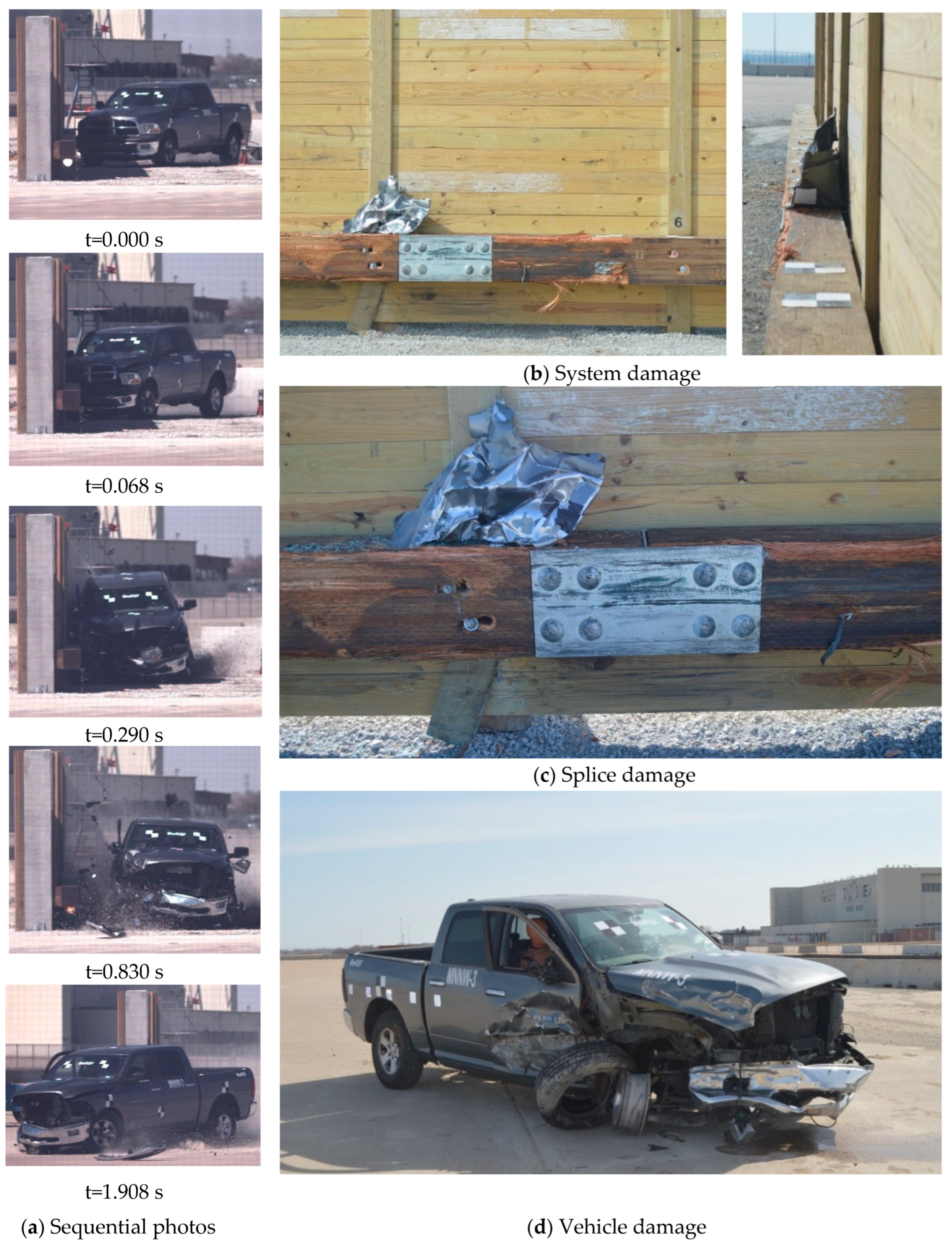
Test MNNW-3 utilized a 2281 kg pickup truck traveling at 98.5 km/h and 25.9°. The target impact point was again positioned 1100 mm upstream of the splice between posts 6 and 7, based on results from Test MNNW-1 to promote snag interaction with the batten and rail splice. The actual impact occurred 46 mm downstream of the intended location.
As illustrated in Figure 8, the barrier exhibited limited structural damage, including contact scarring, splintering of the timber rail, and visible bolt displacement. Additional marks were recorded on the front face of the noise wall and the wooden spacers. Field measurements indicated a maximum permanent lateral set of 10 mm at rail height near post 7 and midspan between posts 6 and 7. The dynamic deflection reached 177.8 mm at the top of post 7, as extracted from high-speed video footage.
The pickup truck experienced moderate deformation, predominantly on the right front corner and side. No violations of the MASH 2016 occupant compartment criteria were observed. The highest deformation, 139.7 mm, was recorded at the right front side panel.

6. Discussion

6.1. Crash Performance and Structural Response

The results of crash tests MNNW-1, MNNW-2, and MNNW-3 indicate that the modified glulam noise wall and rubrail system successfully contained and redirected the vehicles while maintaining controlled lateral displacements. There were no detached elements or fragments that posed a threat to the occupant compartment or other road users. The test vehicles remained upright throughout the impact events, and there were no signs of deformation or intrusion into the occupant compartments that could result in serious injury.
Vehicle roll, pitch, and yaw were within acceptable ranges and did not contribute to vehicle instability or increased occupant risk. The calculated OIVs and 0.010 s average ORAs in both longitudinal and lateral directions were within the performance limits defined by MASH 2016. These occupant risk values, along with angular displacements, are summarized in Table 1. Based on these results, the barrier system met the required impact performance criteria.
After each test, lateral barrier forces were estimated using vehicle accelerometer and rate transducer data. Longitudinal and lateral accelerations recorded at the vehicle center of gravity were smoothed using a 50-millisecond moving average. These averaged values were combined with yaw angle data to estimate the loads applied to the barrier system in both directions. The lateral barrier forces from MNNW-1, MNNW-2, MNNW-3, and the reference test MNTR-1 were compared, as shown in Figure 9.
Tests MNNW-1 and MNNW-3 involved the 2270P pickup truck and had impact severities of 158.9 kJ and 163.3 kJ, respectively. The peak barrier forces recorded in these two tests were 310.5 kN and 324.3 kN, which indicates that the front-mounted and back-mounted wall configurations performed similarly. However, the secondary impact from the rear axle was more significant in MNNW-1, and the vehicle also showed more rear axle damage compared to MNNW-3.
Test MNTR-1 involved a lighter vehicle and had a lower impact severity of 138.5 kJ. The corresponding peak force was 230.0 kN. Although the impact severity in MNNW-1 was only 15 percent higher than that in MNTR-1, the estimated peak force was about 35 percent greater. Similarly, MNNW-2, which used a small car, resulted in a lateral force of 231.8 kN. However, this impact had a shorter duration compared to the tests with pickup trucks.
Contrary to expectations, the dynamic deflections of the barrier did not follow a direct correlation with impact force. In MNNW-1, with the pickup truck, the maximum lateral dynamic deflection was 96.5 mm. In MNNW-2, using the small car, the deflection reached 114.3 mm. MNNW-3 showed the highest deflection of 177.8 mm. This variation is likely related to soil disturbance around the barrier posts. All concrete posts were reused across tests, and the surrounding soil was not re-compacted between tests. Only minor soil filling was conducted to plumb the posts, which may have left gaps or loose soil below grade. As a result, subsequent impacts likely experienced reduced lateral resistance due to these soil conditions.
Based on the estimated lateral forces in Figure 9, the deflection responses observed in MNNW-1 and MNNW-3 would likely have been nearly identical if the surrounding soil had been uniformly compacted. These findings suggest that the post and barrier system can tolerate multiple impacts without needing immediate repair or resetting, provided the embedment depth is sufficient. However, systems with reduced embedment depths may require maintenance after impact events, particularly if soil conditions are poor.
In MNTR-1, the measured lateral dynamic deflection was 301 mm at the top of a 4.88 m post with 1.83 m of embedment. This was significantly greater than the 96.5 mm measured at the same height in MNNW-1, despite only a moderate increase in impact severity. This difference highlights the increased stiffness of the modified noise wall system, which is likely due to the use of deeper post embedment, the addition of glulam planks, and stiffer soil.
While the primary emphasis of this study was on evaluating the structural performance of the glulam timber rubrail and noise wall system under MASH TL-3 impact conditions, occupant safety remains an equally critical component of crashworthiness assessment. Even in the absence of significant vehicle structural deformation, head and neck injuries may occur; therefore, occupant risk metrics serve as an essential complement to structural response data by providing direct insight into potential injury mechanisms and occupant protection performance.
The measured THIV values were 10.34 m/s, 9.90 m/s, and 10.78 m/s for tests MNNW-1, MNNW-2, and MNNW-3, respectively. These values exceed the 9.17 m/s screening criterion widely cited in the European EN 1317 standard for road restraint systems [22], indicating that in an EN 1317 context, the barrier system would not strictly meet the “preferred” threshold for minimizing head contact velocities. However, it is important to emphasize that the AASHTO MASH (2016) criteria, which govern crash testing in the United States, do not prescribe explicit limits for THIV or PHD. Instead, MASH evaluates occupant safety primarily using Occupant Impact Velocity (OIV 12.2 m/s) and Occupant Ridedown Acceleration (ORA   20.49 g). In the present study, all OIV and ORA values satisfied these MASH requirements, confirming compliance with the governing crash test standard.
The post-impact PHD values also remained within conservative ranges (6.17–11.47 g), suggesting limited risk of high-severity cranial acceleration events. Previous work by Berthelson et al. [23] showed that even moderate severity frontal impacts can produce neck extension and flexion loads that warrant careful consideration, while Deng et al. [24] demonstrated through finite-element reconstructions of real-world crash cases that localized skull stress and brain tissue strain can correlate with specific injury outcomes. Although the present study did not incorporate numerical occupant models, the combination of compliant MASH occupant risk values (OIV and ORA) with moderate THIV and PHD levels suggests that the tested glulam systems would perform favorably in mitigating head and neck injury risks relative to conventional rigid roadside structures. Future work will explicitly incorporate finite-element occupant models to examine injury mechanisms and to assess how refinements in rubrail stiffness and detailing might further reduce head contact velocity measures.

6.2. Comparative Performance, Service Life, and Sustainability

The study demonstrated that the glulam noise wall and rubrail system can achieve crash performance outcomes consistent with MASH TL-3 impact safety requirements, while also offering advantages of reduced structural mass and lowered embodied carbon relative to reinforced concrete and structural steel alternatives. Although concrete and steel barriers exhibit higher resistance to extreme impact forces beyond TL-3, glulam systems provide sufficient energy absorption for design-level impacts, comparable acoustic attenuation, and greater sustainability benefits.
Glulam noise barrier systems are expected to achieve a service life of 30–40 years with appropriate preservative treatments and periodic maintenance, similar to structural timber bridge components. While environmental exposure may lead to the gradual degradation of mechanical properties, the crash performance evaluations presented herein represent the condition of new installations. Scheduled inspections and maintenance can mitigate service life effects on structural and safety performance.
Published whole-building life cycle assessments indicate that mass timber systems can reduce cradle-to-grave global warming potential relative to functionally equivalent reinforced concrete and structural steel buildings, with reported reductions of approximately 39–51% versus reinforced concrete and 28–34% versus structural steel. Larger apparent reductions are reported when Module D credits for biogenic carbon storage and material recyclability are included [25]. Earlier cradle-to-gate comparisons of laminated timber versus reinforced concrete also found lower impacts in most categories, comparable process energy, and a higher share of renewable feedstock energy for timber alternatives [26]. Although these results are building-oriented, they align with International Organization for Standardization (ISO)- and American Society for Testing and Materials (ASTM)-conformant Whole Building Life Cycle Assessment (WBLCA) practice and support the use of glulam as a lower-embodied-carbon option for noise walls where functional performance is comparable [25].
From a maintenance perspective, the service life of timber components is governed primarily by moisture management. Proper detailing that limits wetting, together with durable species or modification treatments such as acetylation, impregnation, or protective coatings, can provide long service life with periodic coating renewal and localized, modular replacement when needed [27]. In contrast, reinforced concrete and steel systems commonly experience durability challenges associated with reinforcement corrosion, spalling, or corrosion protection upkeep. End-of-life pathways for timber elements also include reuse and bioenergy recovery, which can further influence life cycle burdens [26]. Given that sector-specific life cycle cost data for transportation noise walls remain limited, future work will compile in-service maintenance records and perform a noise-wall-specific life cycle costing analysis to quantify long-term economic performance alongside environmental metrics [28].

7. Limitations and Future Work

While this research relied exclusively on full-scale vehicle crash testing to evaluate the performance of a glulam noise wall and rubrail system under MASH TL-3 impact conditions, the scope remains limited to common passenger vehicles and pickup trucks. Although this reflects the primary target application, it does not encompass heavier vehicles or motorcycles. Future work could expand to TL-4 and TL-5 impact conditions, incorporating both full-scale testing and advanced finite element (FE) modeling to complement experimental findings. Such models could simulate the dynamic response of glulam components under various impact scenarios, enabling parametric studies on rail geometry, fastener type and placement, connection detailing, and post spacing without the cost and logistical constraints of repeated full-scale testing. Incorporating advanced constitutive models for glulam and connection assemblies would further allow the prediction of localized stress distributions, progressive damage, and potential failure modes under higher impact energy levels. This integrated approach would provide a robust framework for optimizing design parameters prior to field implementation.

8. Summary, Conclusions, and Recommendations

Three full-scale crash tests were conducted on glulam timber rubrail and noise wall configurations to evaluate their performance under MASH TL-3 impact conditions. The following specific findings were observed:
  • All tested systems (MNNW-1, MNNW-2, and MNNW-3) successfully contained and redirected 1100C and 2270P vehicles under test designation nos. 3-10 and 3-11. The structural integrity of both the rubrail and wall system was maintained, demonstrating compliance with MASH 2016 impact safety performance criteria.
  • Both back-side and front-side mounted noise wall systems showed comparable crash performance. Although the front-side configuration was tested only under 3-11 impact conditions, the similarity in performance to the back-side system suggests it would also meet 3-10 requirements.
  • The tested systems incorporated embedment depths greater than the MnDOT minimum standard of 1.8 m [29,30] and taller wall elements, resulting in stiffer behavior and acceptable safety performance. These results indicate that systems with equal or greater embedment and stiffness are likely to meet MASH TL-3 criteria, while reduced embedment depths may increase deflections but still remain within acceptable limits.
  • Both round-head bolts recessed 3 mm and hex head bolts recessed 16 mm performed acceptably in the rubrail-to-post connection [31], demonstrating that either option is suitable for field applications without compromising crashworthiness.
  • The transition between front-side and back-side mounted segments presents a potential vehicle snagging risk due to the overlap of structural components. While no significant snagging was observed, future research should further investigate this area and evaluate protective treatments at transitions and system ends to minimize vehicle interaction hazards.
  • Overall, these findings demonstrate that glulam noise wall and rubrail systems can provide sustainable alternatives to conventional roadside barriers, thereby contributing to sustainable infrastructure development while meeting modern crashworthiness requirements.

Author Contributions

Conceptualization, R.K.F. and J.D.S.; methodology, R.K.F. and J.D.S.; software, R.K.F., T.Y.Y. and J.D.S.; validation, R.K.F., J.D.S. and T.Y.Y., formal analysis, R.K.F., J.D.S. and T.Y.Y.; investigation, R.K.F., J.D.S., T.Y.Y. and Q.A.A.; resources, R.K.F.; data curation, R.K.F., J.D.S., T.Y.Y., Q.A.A. and M.A.B.; writing—original draft preparation, T.Y.Y.; writing—review and editing, R.K.F., J.D.S., Q.A.A. and M.A.B.; visualization, R.K.F., J.D.S., T.Y.Y. and Q.A.A.; supervision, R.K.F.; project administration, R.K.F.; funding acquisition, R.K.F. All authors have read and agreed to the published version of the manuscript.

Funding

This research was completed with funding from the Federal Highway Administration, U.S. Department of Transportation and the Minnesota Department of Transportation under Contract/Grant No. TPF-5(193), Supplement #115.

Data Availability Statement

The data presented in this study are available on request from the corresponding author. The data are not publicly available due to ongoing research using a part of the data.

Acknowledgments

The authors wish to acknowledge several sources that made a contribution to this project: (1) Minnesota Department of Transportation for sponsoring this project; (2) Michelle Moser and Michael Elle from the Minnesota Department of Transportation for providing guidance throughout the project; and (3) MwRSF personnel for preparing CAD details, ordering materials, constructing and removing the barriers, and conducting the full-scale crash tests.

Conflicts of Interest

The authors declare no conflicts of interest.

References

  1. Martinez-Orozco, J.M.; Barba, A. Determination of insertion loss of noise barriers in Spanish roads. Appl. Acoust. 2022, 186, 108435. [Google Scholar] [CrossRef]
  2. Silva, L.T.; Oliveira, I.S.; Silva, J.F. The impact of urban noise on primary schools: Perceptive evaluation and objective assessment. Appl. Acoust. 2016, 106, 2–9. [Google Scholar] [CrossRef]
  3. Zhang, X.; Liu, R.; Cao, Z.; Wang, X.; Li, X. Acoustic performance of a semi-closed noise barrier installed on a high-speed railway bridge: Measurement and analysis considering actual service conditions. Measurement 2019, 138, 386–399. [Google Scholar] [CrossRef]
  4. Meyer, M.D.; Weigel, B. Climate change and transportation engineering: Preparing for a sustainable future. J. Transp. Eng. 2011, 137, 393–403. [Google Scholar] [CrossRef]
  5. Žemaitis, P.; Linkevičius, E.; Aleinikovas, M.; Tuomasjukka, D. Sustainability impact assessment of glue laminated timber and concrete-based building materials production chains: A Lithuanian case study. J. Clean. Prod. 2021, 321, 129005. [Google Scholar] [CrossRef]
  6. Maxineasa, S.G.; Entuc, I.-S.; Taranu, N.; Florenta, I.; Secu, A. Environmental performances of different timber structures for pitched roofs. J. Clean. Prod. 2018, 175, 164–175. [Google Scholar] [CrossRef]
  7. Petruch, M.; Walcher, D. Timber for future? Attitudes towards timber construction by young millennials in Austria: Marketing implications from a representative study. J. Clean. Prod. 2021, 294, 126324. [Google Scholar] [CrossRef]
  8. American Association of State Highway and Transportation Officials (AASHTO). AASHTO LRFD Bridge Design Specifications, 9th ed.; AASHTO: Washington, DC, USA, 2020. [Google Scholar]
  9. American Association of State Highway and Transportation Officials (AASHTO). Manual for Assessing Safety Hardware; AASHTO: Washington, DC, USA, 2016. [Google Scholar]
  10. Li, X.; Ashraf, M.; Li, H.; Zheng, X.; Wang, H.; Al-Deen, S.; Hazell, P.J. An experimental investigation on parallel bamboo strand lumber specimens under quasi static and impact loading. Constr. Build. Mater. 2019, 228, 116724. [Google Scholar] [CrossRef]
  11. Bullard, D.L.; Buth, C.E.; Williams, W.F.; Menges, W.L.; Schoeneman, S.K. NCHRP REPORT 350 Evaluation of the T501 Bridge Rail with Soundwall; FHWA/TX-01/408460-F; Texas Transportation Institute, Texas A&M University System: College Station, TX, USA, 2001. [Google Scholar]
  12. Ross, H.E.; Sicking, D.L.; Zimmer, R.A.; Michie, J.D. Recommended Procedures for the Safety Performance Evaluation of Highway Features; Transportation Research Board: Washington, DC, USA, 1993. [Google Scholar]
  13. Polivka, K.A.; Hascall, J.A.; Faller, R.K.; Rohde, J.R.; Holloway, J.C.; Sicking, D.L.; Kurz, K. Design and Evaluation of CYRO’s Paraglas Soundstop TL-4 Noise Barrier System; Transp. Res. Rep. No. TRP-03-160-05; Midwest Roadside Safety Facility, University of Nebraska–Lincoln: Lincoln, NE, USA, 2005. [Google Scholar]
  14. Faller, R.K.; Polivka, K.A.; Humphries, E.; Kurz, K.; Sicking, D.L.; Hascall, J.A. Test level 4 noise wall for attachment to concrete traffic barriers. Transp. Res. Rec. 2006, 1984, 56–68. [Google Scholar] [CrossRef]
  15. Polivka, K.A.; Rohde, J.R.; Faller, R.K.; Hollaway, J.C.; Sicking, D.L. Design and Evaluation of Minnesota’s Timber Rub-Rail Noise Barriers; Midwest Roadside Safety Facility, University of Nebraska–Lincoln: Lincoln, NE, USA, 2005. [Google Scholar]
  16. Bligh, R.P.; Briaud, J.L.; Abu-Odeh, A.; Seaz, D.O.; Maddah, L.S.; Kim, K.M. Design Guidelines for Test Level 3 (TL-3) Through Test Level 5 (TL-5) Roadside Barrier Systems Placed on Mechanically Stabilized Earth (MSE) Retaining Wall; Texas A&M Transportation Institute: College Station, TX, USA, 2017. [Google Scholar]
  17. American Wood Council. NDS National Design Specification for Wood Construction: With Commentary; American Wood Council: Washington, DC, USA, 2015. [Google Scholar]
  18. Hinch, J.; Yang, T.L.; Owings, R. Guidance Systems for Vehicle Testing; ENSCO, Inc.: Springfield, VA, USA, 1986. [Google Scholar]
  19. Center of Gravity Test Code—SAE J874 March 1981, SAE Handbook Vol. 4; Society of Automotive Engineers, Inc.: Warrendale, PA, USA, 1986.
  20. MacInnis, D.; Cliff, W.; Ising, K. A Comparison of the Moment of Inertia Estimation Techniques for Vehicle Dynamics Simulation; SAE Tech. Pap. Ser. 970951; Society of Automotive Engineers, Inc.: Warrendale, PA, USA, 1997. [Google Scholar]
  21. Society of Automotive Engineers (SAE). Instrumentation for Impact Test—Part 1—Electronic Instrumentation; SAE J211/1 MAR95; SAE: Warrendale, PA, USA, 2007. [Google Scholar]
  22. CEN (European Committee for Standardization). EN 1317-1:2010; Road Restraint Systems—Part 1: Terminology and General Criteria for Test Methods. European Committee for Standardization: Brussels, Belgium, 2010.
  23. Berthelson, P.; Ghassemi, P.; Wood, J.W.; Liu, Y.; Al-Graitti, A.J.; Jones, M.D.; Chowdhury, S.; Prabhu, R.K. Evaluation of Occupant Neck Injury Response to Varied Impact Conditions Using a Finite Element-Mathematical Surrogate Modeling Approach. Int. J. Crashworthiness 2022, 27, 1726–1742. [Google Scholar] [CrossRef]
  24. Deng, X.-Q.; Du, Z.; Feng, H.; Wang, S.; Luo, H.; Liu, Y. Investigation on the Modeling and Reconstruction of Head Injury Accident Using ABAQUS/Explicit. Bioengineering 2022, 9, 723. [Google Scholar] [CrossRef]
  25. Kumar, V.; Lo Ricco, M.; Bergman, R.D.; Nepal, P.; Poudyal, N.C. Environmental Impact Assessment of Mass Timber, Structural Steel, and Reinforced Concrete Buildings Based on the 2021 International Building Code Provisions. Build. Environ. 2024, 251, 111195. [Google Scholar] [CrossRef]
  26. Robertson, A.B.; Lam, F.C.F.; Cole, R.J. A Comparative Cradle-to-Gate Life Cycle Assessment of Mid-Rise Office Building Construction Alternatives: Laminated Timber or Reinforced Concrete. Buildings 2012, 2, 245–270. [Google Scholar] [CrossRef]
  27. Ramage, M.H.; Burridge, H.; Busse-Wicher, M.; Fereday, G.; Reynolds, T.; Shah, D.U.; Wu, G.; Yu, L.; Fleming, P.; Densley-Tingley, D.; et al. The Wood from the Trees: The Use of Timber in Construction. Renew. Sustain. Energy Rev. 2017, 68, 333–359. [Google Scholar] [CrossRef]
  28. Dodoo, A.; Gustavsson, L.; Sathre, R. Life Cycle Primary Energy Implication of Retrofitting a Wood-Framed Apartment Building to Passive House Standard. Resour. Conserv. Recycl. 2010, 54, 1152–1160. [Google Scholar] [CrossRef]
  29. Minnesota Department of Transportation. Glue Laminated Rubrail (Concrete Posts); Minnesota Department of Transportation: Saint Paul, MN, USA, 2014. [Google Scholar]
  30. Minnesota Department of Transportation. Wood Planking Noise Wall with Concrete Posts; Minnesota Department of Transportation: Saint Paul, MN, USA, 2016. [Google Scholar]
  31. Schmidt, J.D.; Asselin, N.; Faller, R.K.; Fallet, W.G.; Holloway, J.C.; Lechtenberg, K.A. Evaluation of the Minnesota Noise Wall and Rubrail System; Midwest Roadside Safety Facility, University of Nebraska–Lincoln: Lincoln, NE, USA, 2019. [Google Scholar]
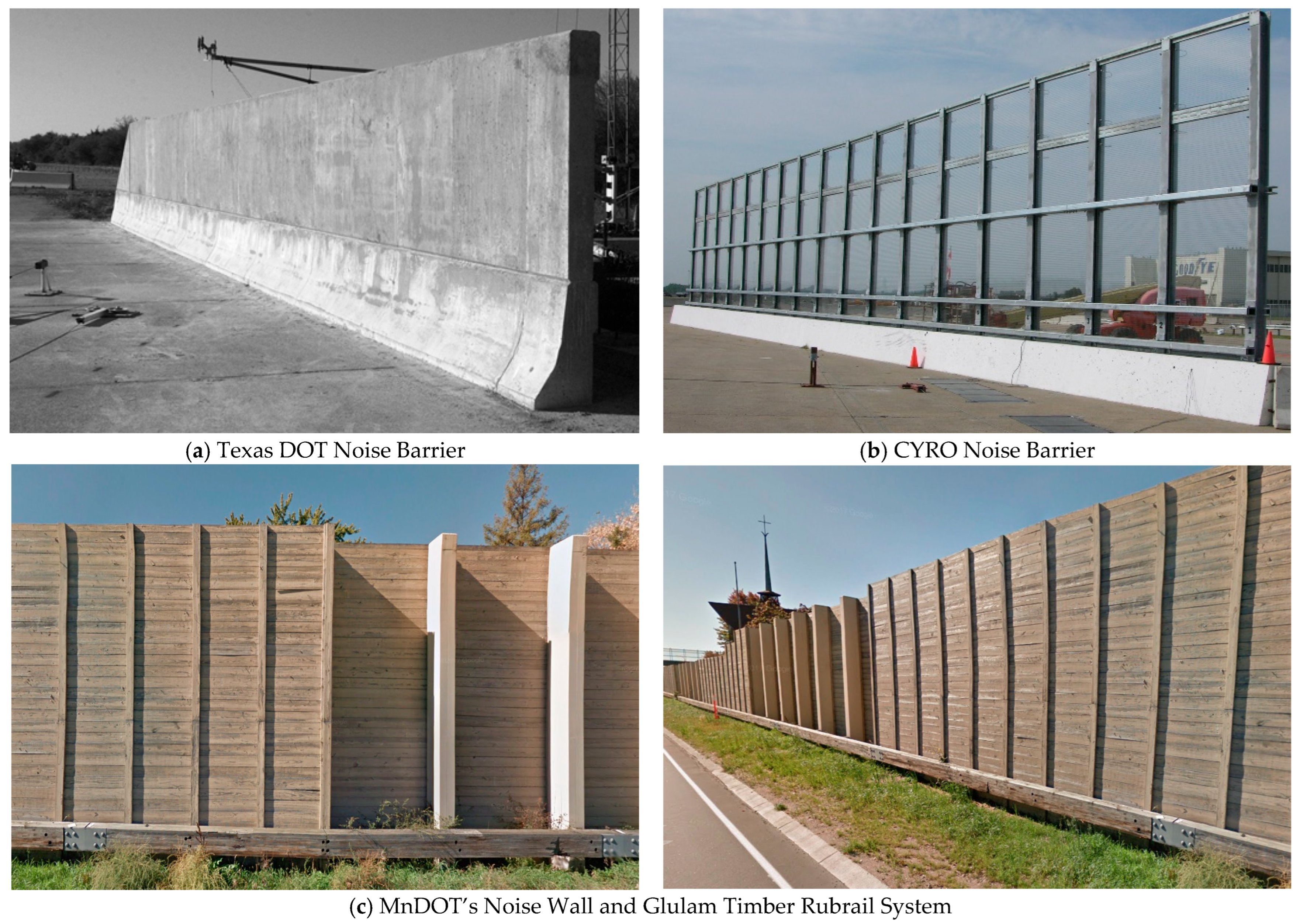
Figure 1. Examples of existing crashworthy noise wall systems: (a) Texas DOT barrier [11], (b) CYRO noise barrier [13,14], and (c) MnDOT noise wall [15].
Infrastructures 10 00226 g001
Figure 2. Details of the noise wall and glulam timber rubrail system. (Numbers in square brackets indicate dimensions in millimeters.).
Infrastructures 10 00226 g002
Figure 3. Redesigned noise wall and glulam timber rubrail system, (a) layout used in tests MNNW-1 and MNNW-2, (b) layout used in test MNNW-3, (c) overhead view of system configuration, and (d) details of rubrail, offset blocks, and splices.
Infrastructures 10 00226 g003
Figure 4. Test vehicles used in Tests MNNW-1 through to MNNW-3, including 2270P pickup trucks and a 1100C small car under MASH TL-3 conditions.
Infrastructures 10 00226 g004
Figure 5. Photograph of SLICE-1 and SLICE-2 accelerometer packages.
Infrastructures 10 00226 g005
Figure 6. Results from test MNNW-1: (a) sequential crash test photos, (b) overall system damage, (c) splice damage, and (d) vehicle damage.
Infrastructures 10 00226 g006
Figure 7. Results from test MNNW-2: (a) sequential crash test photos, (b) overall system damage, (c) splice damage, and (d) vehicle damage.
Infrastructures 10 00226 g007
Figure 8. Results from test MNNW-3 results: (a) sequential crash test photos, (b) overall system damage, (c) splice damage, and (d) vehicle damage.
Infrastructures 10 00226 g008
Figure 9. Estimated lateral barrier impact forces for each full-scale crash test. Test MNNW-1 and MNNW-3 involved the 2270P pickup truck with impact severities of 158.9 kJ and 163.3 kJ, respectively. Test MNTR-1 also involved a 2270P pickup truck but was conducted under NCHRP Report 350 criteria with an impact severity of 138.5 kJ. Test MNNW-2 used an 1100C small car and had an impact severity of 59.7 kJ.
Infrastructures 10 00226 g009
Table 1. Summary of OIV, ORA, THIV, PHD, and ASI values from full-scale vehicle crash tests.
Evaluation CriteriaTest MNNW-1Test MNNW-2Test MNNW-3MASH 2016
Limits
OIV, m/sLongitudinal−7.34−7.23−8.12±12.2 (±40)
Lateral−7.95−8.66−7.46±12.2 (±40)
ORA, g’sLongitudinal−7.59−6.2−8.2±20.49
Lateral−7.33−4.55−6.64±20.49
MAX.
ANGULAR
DISPL.
deg.
Roll26.7−3.36.7±75
Pitch−21−2.96.1±75
Yaw30.1−37.2−33.7not required
THIV, m/s10.349.910.78not required
PHD, g’s9.146.1711.47not required
ASI1.462.141.53not required
Disclaimer/Publisher’s Note: The statements, opinions and data contained in all publications are solely those of the individual author(s) and contributor(s) and not of MDPI and/or the editor(s). MDPI and/or the editor(s) disclaim responsibility for any injury to people or property resulting from any ideas, methods, instructions or products referred to in the content.