1. Introduction
Reinforced concrete (RC) columns are among the most critical load-bearing elements in civil infrastructure, especially in seismically active zones and heavily loaded structures such as bridges, high-rise buildings, and piers. The structural performance and ultimate capacity of these columns under axial or combined axial–flexural loading are highly influenced by the efficiency of lateral confinement, which restrains the lateral expansion of concrete and delays spalling, thereby enhancing strength, ductility, and energy dissipation [
1,
2,
3]. In typical RC construction, confinement is provided by transverse steel reinforcement, usually in the form of closed-loop stirrups or ties spaced along the column height. Adequate confinement has been proven to significantly improve both the peak axial strength and post-peak deformation behavior of RC columns, which is critical in delaying collapse under extreme loads such as earthquakes, impacts, and blasts [
4]. Concrete-Filled Steel Tube (CFT) columns are another well-established confinement solution that provide continuous external restraint to the concrete core, enhancing both strength and ductility under axial and seismic loading [
5,
6,
7]. Ma et al. [
8] showed that precast steel-reinforced grout jackets combining steel and cementitious grout can efficiently increase the strength and ductility of pre-damaged RC columns.
Despite its structural benefits, steel-based confinement presents considerable drawbacks, particularly in corrosive or durability-critical environments. Steel stirrups and steel tubes are prone to corrosion when exposed to chloride-laden air (e.g., marine environments), carbonation, de-icing salts, or cyclic wet–dry conditions [
9]. Corrosion reduces the cross-sectional area, leads to cracking and spalling of concrete, and degrades the confinement pressure, often without early visible signs, ultimately compromising structural integrity [
10]. In addition, seismic design provisions often require closely spaced transverse reinforcement to ensure ductility and shear resistance, which can result in reinforcement congestion that impedes concrete placement and consolidation, increasing the risk of voids, honeycombing, and poor bonding between concrete and reinforcement [
11]. These limitations have led researchers to explore alternative confinement strategies that can offer equivalent or improved structural performance while mitigating the shortcomings of traditional steel.
In this context, fiber-reinforced polymer (FRP) materials have emerged as attractive alternatives to steel in both new construction and retrofit applications. FRPs, such as carbon (CFRP), glass (GFRP), aramid (AFRP), and more recently basalt fiber-reinforced polymer (BFRP), are corrosion-resistant, lightweight, nonmagnetic, and possess high tensile strength [
12,
13,
14,
15]. They have been widely used in the form of external jackets or wraps to retrofit existing columns, enhancing ductility and axial capacity through confinement [
16,
17,
18]. Lam and Teng [
19] and Moussa et al. [
20] demonstrated that externally bonded CFRP wraps significantly increase the strength and energy absorption capacity of RC columns, especially under monotonic and cyclic axial compression. Specifically, Moussa et al. [
20] showed through the testing of nine rectangular RC columns that CFRP confinement could offset strength reductions due to higher aspect ratios; for example, increasing the aspect ratio from 1 to 2 led to a peak stress reduction of up to 29.9% in two-layer CFRP-confined columns compared to square sections. Their work also proposed a refined predictive model for strength enhancement, validated against a database of 127 FRP-confined rectangular column tests. Similar results were observed in GFRP and BFRP-confined columns [
21,
22,
23]. Hou et al. [
23] studied BFRP jacketing for corroded and pre-damaged circular RC columns and reported that adding BFRP layers increased the ultimate strength by up to 98% and the ultimate strain by up to 926%, demonstrating its effectiveness in restoring capacity. However, external confinement is primarily suitable for retrofit, and less so for new construction.
More recent studies have explored the internal application of FRP ties or stirrups, where they serve as direct substitutes for steel ties in new RC members. Elsayed et al. [
24] stated that the internal confinement systems are preferred for constructability and aesthetic reasons. Zhou et al. [
25] and Zeng et al. [
26] showed that concrete columns confined internally with FRP spirals or hoops exhibit improved ductility and strain capacity, although their performance is highly sensitive to tie detailing. For square or rectangular columns, internal FRP ties often suffer from non-uniform confinement pressure, with stress concentrations at the corners that reduce overall effectiveness [
27]. In addition, conventional FRP stirrups, typically manufactured via manual bending of pultruded bars, are prone to premature rupture at bent corners due to fiber damage, delamination, or micro-cracking, which significantly reduces their usable strength in confinement applications [
28,
29]. This limitation has hindered the widespread use of internal FRP confinement, particularly in critical structural elements [
30,
31]. Elsayed and Wu [
32] recently showed that continuous filament wound BFRP ties offer promising improvements in strength retention and practical constructability.
To address these challenges, this study introduces and experimentally investigates an innovative internal confinement system using novel closed rectangular BFRP ties fabricated by a continuous filament winding process. Unlike conventional FRP stirrups that are typically hand-bent from pultruded bars and often suffer from fiber damage or micro-cracking at bent corners, this automated winding method ensures uninterrupted fiber continuity around the entire tie geometry. This significantly improves tensile strength retention at corner regions, minimizes stress concentrations, and reduces the risk of premature rupture, which has been a persistent drawback of hand-bent FRP stirrups in internal confinement applications. Although continuous filament winding is well established for producing round FRP products, its application to rectangular closed ties for internal confinement is rare and fills an important research gap by providing a robust, practical alternative to traditional transverse reinforcement for new RC construction.
The present research evaluates the axial compression behavior of square RC columns confined using three different reinforcement configurations: (1) conventional steel ties, serving as a benchmark, (2) BFRP-only ties at two different vertical spacings (45 mm and 90 mm), and (3) hybrid systems combining steel ties and interleaved BFRP ties. The objective is to assess how confinement material and volumetric ratio influence the failure mode, load-carrying capacity, stress–strain response, ductility, and confinement efficiency of RC columns. Five RC column specimens were constructed and tested under monotonic axial loading. The results are compared to identify the most effective and structurally viable confinement strategy. The novelty of this study lies in the development and experimental validation of a closed-loop rectangular BFRP tie, manufactured to overcome the geometric and strength limitations of traditional FRP stirrups. The ties demonstrate high tensile strength retention at bends, improved energy dissipation, and superior post-peak performance, especially when used in hybrid confinement schemes. This research contributes to the growing interest in hybrid reinforcement systems, offering a pathway to more durable, resilient, and corrosion-resistant structural components for use in aggressive environments and seismic zones.
2. Experimental Program
2.1. Materials’ Properties
This study employed three primary construction materials: normal-weight concrete, deformed steel reinforcement bars, and novel rectangular BFRP ties. All materials were characterized through standardized mechanical testing procedures to ensure consistency across specimens and to enable accurate evaluation of the axial performance of the confined RC columns. The material properties provided the basis for understanding the confinement mechanisms and the structural response under axial loading.
2.1.1. Concrete
All five column specimens were cast using normal-weight concrete with a target 28-day compressive strength of 30 MPa, reflecting typical structural concrete used in RC columns for buildings and bridges. To maintain quality control, concrete was prepared in three separate batches, each assigned to one or two column specimens. Consistent workability was achieved across batches, with an average slump of 100 mm at the time of casting. For each batch, nine cylindrical samples (100 mm × 200 mm) were prepared and cured under laboratory conditions. On the day of column testing, compressive strength tests were performed following ASTM C39/C39M-17 [
33] to determine the actual concrete strength. The measured 28-day compressive strengths ranged from 32 MPa to 36 MPa, confirming the quality and uniformity of the concrete mix. The average unconfined concrete strength (
fco) was used as a baseline for assessing confinement efficiency in each specimen.
2.1.2. Steel Reinforcement
Two types of deformed steel reinforcement bars were used in the fabrication of the RC column specimens: 13 mm diameter bars for longitudinal reinforcement and 10 mm diameter bars for transverse ties. Both types conform to SD345-grade steel, commonly used in structural concrete applications due to its high strength and ductility. To ensure accurate representation of material behavior in the structural performance of the columns, the mechanical properties of the steel bars were determined through monotonic tensile tests conducted in accordance with ASTM A370-17b [
34]. For each bar size, three tensile specimens were tested to capture average material properties. The measured properties are summarized in
Table 1. These values reflect consistent quality across bar sizes and confirm that the steel reinforcement meets the mechanical performance requirements for both axial and confinement roles. The transverse steel ties were formed into closed rectangular loops with 135° hooks at the ends, as per conventional reinforcement detailing practices for effective anchorage. Their configuration was designed to provide confinement to the concrete core and restraint against longitudinal bar buckling under axial loads. The high ductility of the steel ties contributed to the confinement action in the post-yielding phase and influenced the failure modes of the specimens incorporating steel reinforcement.
2.1.3. Proposed Innovative Rectangular BFRP Ties
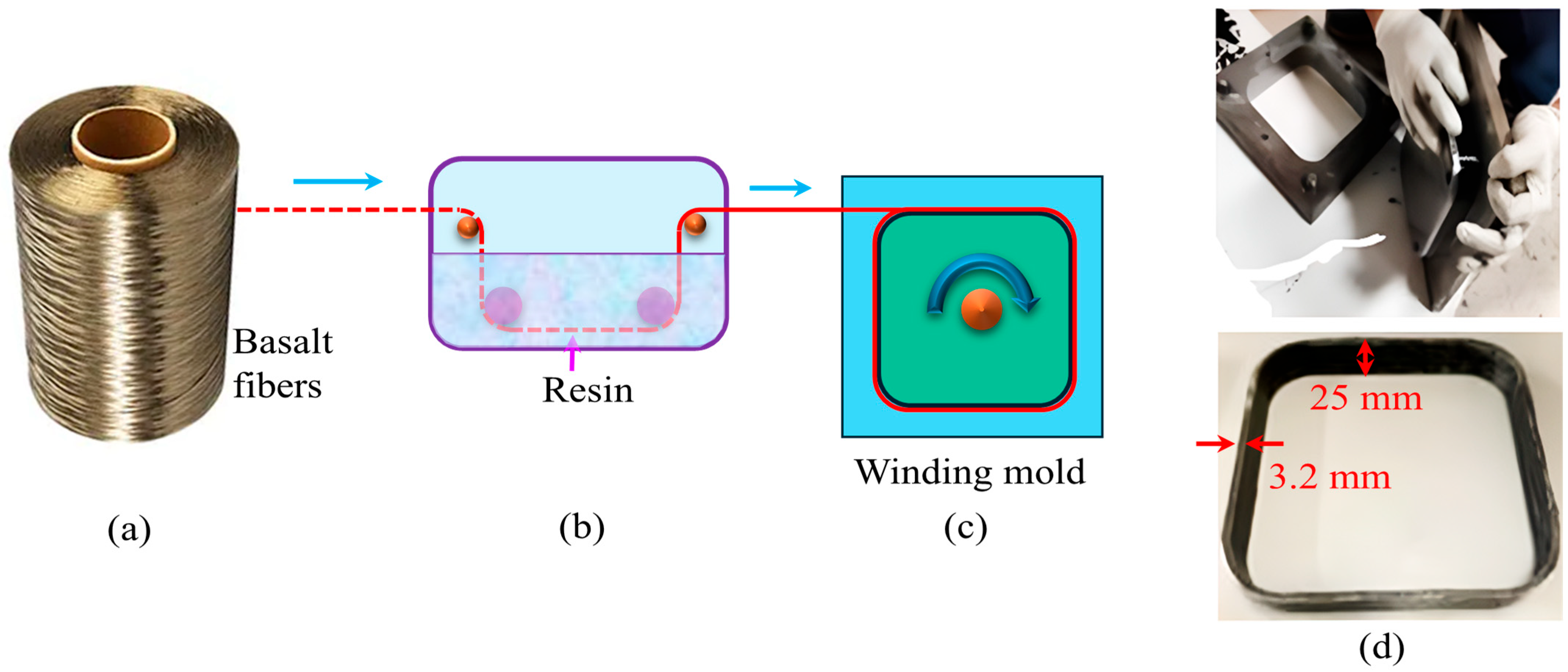
In this study, a novel type of rectangular BFRP tie was developed to serve as an internal confinement reinforcement for RC columns. Unlike conventional FRP stirrups, which are often fabricated by bending straight bars and are prone to premature rupture at corners, the proposed BFRP ties were manufactured using a continuous filament winding process. This automated fabrication method allows for fiber continuity at the corners, eliminates weak zones due to fiber disruption, and results in a single continuous closed loop with no overlaps or splices, ensuring uninterrupted fiber continuity around the entire tie geometry. The ties were fabricated using basalt fiber tows impregnated with epoxy resin and wound around a rectangular steel mold with rounded corners, then cured at room temperature, as shown in
Figure 1. Each tie had an external width of 25 mm, a thickness of 3.2 mm, and a geometry sized to fully encompass the six longitudinal reinforcement bars in the column cross-section. The resulting tie area was designed to be equivalent to that of a 10 mm diameter circular bar to facilitate fair comparison with conventional steel ties.
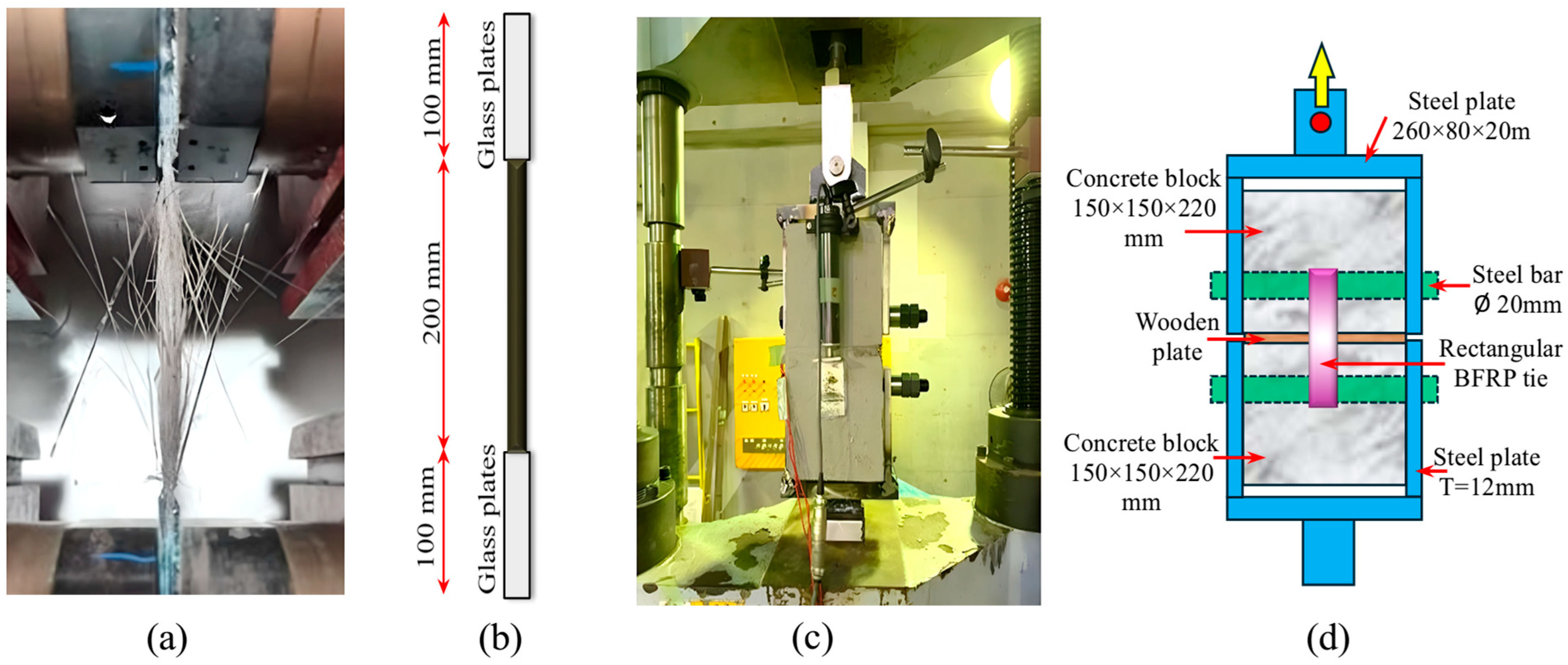
To evaluate the mechanical performance of the BFRP ties, tensile tests were conducted on both straight specimens and bent specimens taken from the corner regions of the rectangular loops, as shown in
Figure 2. The tests followed guidelines from ACI 440.3R [
35] and CSA S806 [
36], which account for the unique linear elastic behavior and brittle failure characteristics of FRP materials. Each set included six samples to ensure statistical reliability. The straight BFRP specimens exhibited a mean tensile strength of 1212.49 MPa, with values ranging from 1181.87 MPa to 1244.53 MPa, and an elastic modulus of 51.39 GPa, as shown in
Table 2. The coefficient of variation (COV) for tensile strength was 2.11%, indicating high manufacturing consistency. The bent BFRP specimens, which were extracted from the corners of the ties with a bend radius of 30 mm, showed a slightly lower average tensile strength of 1133.95 MPa, representing a strength retention of approximately 94% compared to the straight segments. The COV for the bent specimens was 2.88%, also within acceptable limits.
These results demonstrate that the proposed rectangular BFRP ties maintain a high degree of tensile strength and stiffness even at bent regions, which is a key advancement over traditional FRP stirrups. The high corner strength retention confirms the effectiveness of the continuous winding process at minimizing stress concentrations and avoiding early rupture. Additionally, the linear elastic behavior of the BFRP ties until brittle failure allows them to provide reliable confinement pressure without yielding, which enhances their post-peak performance in confined RC columns. The durability, corrosion resistance, and consistent tensile properties of the innovative BFRP ties make them a promising alternative or supplement to conventional steel confinement, particularly in structures exposed to aggressive environmental conditions or requiring enhanced ductility.
2.2. Column Specimen Details
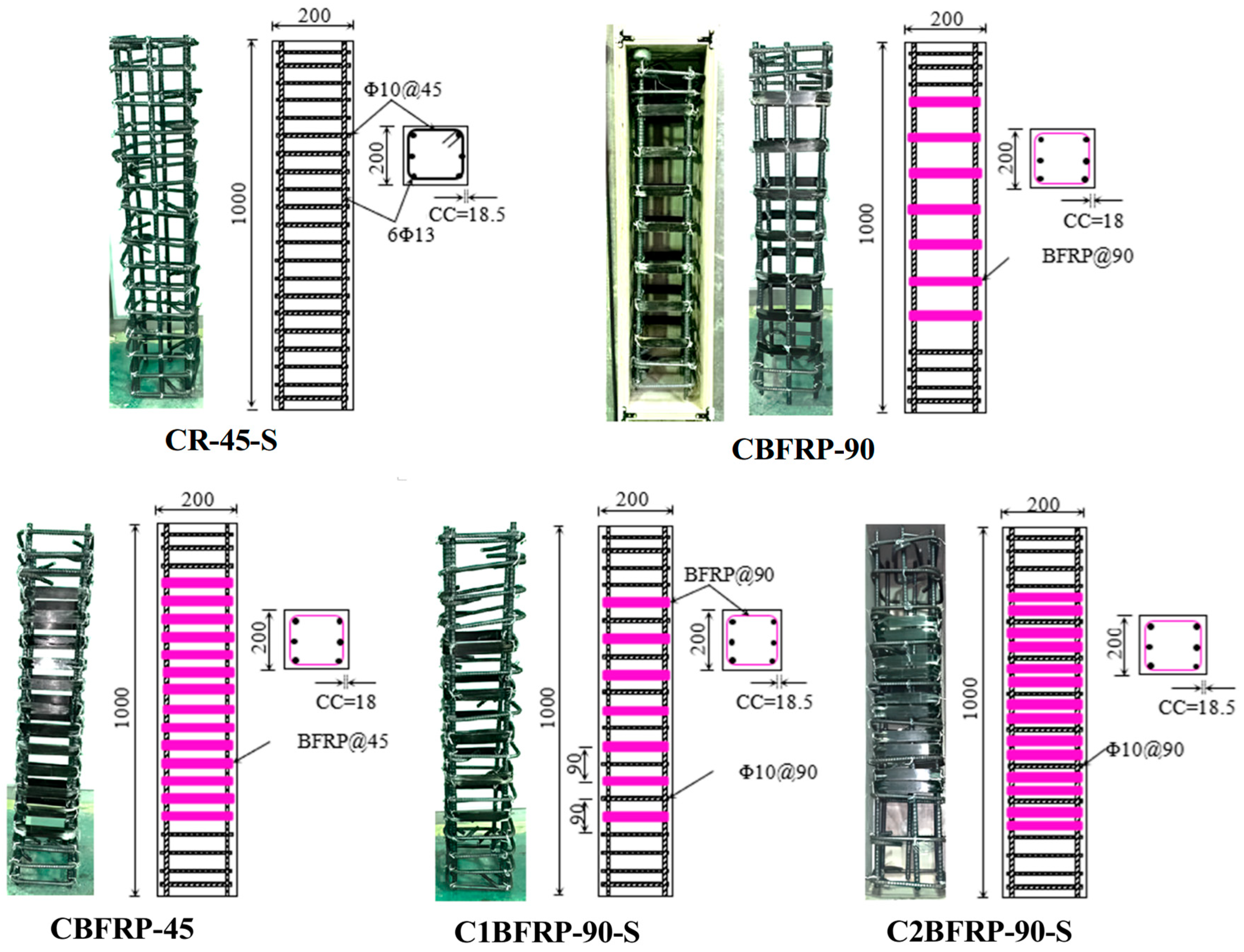
In order to investigate the axial compression performance of RC columns with different confinement systems, a total of five square column specimens were designed and fabricated.
Table 3 provides a summary of the reinforcement layout and geometric details of the tested column specimens. Each specimen had a cross-sectional dimension of 200 mm × 200 mm and a total height of 1000 mm, which was chosen to simulate the critical mid-height region of structural columns while maintaining compatibility with laboratory testing constraints. These dimensions reflect a scale suitable for experimental observation while representing the typical behavior of bridge or building columns subjected to axial loads.
All specimens were identically reinforced with six longitudinal deformed steel bars with a 13 mm diameter, corresponding to a longitudinal reinforcement ratio (
ρl) of 2.00%, as shown in
Figure 3. The layout of longitudinal bars remained constant across all specimens to isolate the effect of transverse confinement. The primary test variable in the experimental program was the type and volumetric ratio of transverse reinforcement, which was altered by varying the material (steel or BFRP), the tie spacing, and the reinforcement configuration. This approach enabled a comprehensive assessment of the confinement effectiveness of novel rectangular BFRP ties in comparison to conventional steel ties and hybrid arrangements. Three confinement schemes were considered: (1) conventional steel-only confinement, (2) BFRP-only confinement using rectangular ties fabricated from basalt fiber-reinforced polymer, and (3) hybrid confinement combining steel and BFRP ties in alternating layers. The steel-only specimen, designated as CR-45-S, was confined by 10 mm diameter closed-loop steel ties with 135° hooks, spaced at 45 mm center-to-center. This configuration provided a transverse steel reinforcement ratio (
ρw) of 2.14% and was intended to serve as a benchmark representing a densely confined conventional column.
To evaluate the performance of the novel BFRP confinement, two additional specimens were reinforced solely with rectangular BFRP ties. These specimens, labeled CBFRP-90 and CBFRP-45, differed in the tie spacing while maintaining the same tie geometry and material. Specimen CBFRP-90 used a tie spacing of 90 mm, resulting in a BFRP reinforcement ratio (ρfw) of 1.09%, while specimen CBFRP-45 used a tie spacing of 45 mm, leading to a ρfw of 2.18%. These configurations allowed for a direct comparison of how tie spacing influences the confinement effectiveness and axial performance of BFRP-confined RC columns. In addition to the steel-only and BFRP-only columns, two hybrid confinement schemes were implemented to assess the synergistic effects of combining steel and BFRP reinforcement. In both hybrid specimens, steel ties were placed at a wider spacing of 90 mm, and rectangular BFRP ties were interleaved between the steel ties. Specimen C1BFRP-90-S incorporated one BFRP tie between each pair of steel ties, yielding a steel ratio (ρw) of 1.07% and a BFRP ratio (ρfw) of 1.09%. Specimen C2BFRP-90-S included two BFRP ties between each pair of steel ties while keeping the same steel layout, resulting in a total BFRP ratio of 2.18%. This progressive increase in the volume of BFRP ties in the hybrid configurations enabled a parametric investigation of their confinement contribution relative to traditional steel ties.
All reinforcement detailing, including bar diameters, tie spacing, and volumetric ratios, was carried out in accordance with the AASHTO LRFD Bridge Design Specifications [
37] and current design guidelines for confined RC columns. Special attention was paid to maintaining uniform concrete cover and minimizing detailing irregularities that could affect test results. The reinforcement arrangements were also carefully designed to allow for meaningful comparisons between different confinement types under identical axial loading conditions in which all column specimens were designed with the same cross-sectional dimensions, concrete strength, and longitudinal reinforcement layout so that the only variables were the type and arrangement of the transverse ties. The configuration of all five specimens provided a balanced and systematic experimental matrix. By comparing columns with steel-only confinement, BFRP-only confinement at two tie spacings, and hybrid confinement with varied BFRP volumes, the study was able to isolate and quantify the contribution of each confinement strategy to the overall axial performance of RC columns.
2.3. Construction and Instrumentation
The five RC column specimens were constructed in a controlled laboratory environment to ensure consistent quality and detailing. Standardized procedures were used for reinforcement placement, formwork assembly, concrete mixing, casting, and curing. Particular care was taken to maintain uniform dimensions, material properties, and reinforcement anchorage, isolating the effects of the different confinement systems under study (
Figure 3).
Reinforcement cages were prepared in advance according to the specifications in
Section 2.2. For specimens with rectangular BFRP ties, the ties were manufactured off-site using a custom filament winding process and integrated into the cages on-site. Mechanical spacers ensured correct vertical spacing (45 mm or 90 mm) and alignment. In hybrid specimens, steel and BFRP ties were alternated as designed. Longitudinal bars were secured within the cages using plastic spacers to maintain clear cover and prevent displacement during casting.
The formwork comprised plywood molds reinforced with steel clamps to resist expansion under concrete pressure. Ready-mix normal-weight concrete was poured vertically in layers and compacted with a high-frequency vibrator to eliminate air pockets, especially around closely spaced ties. After casting, specimens were covered with plastic sheets and kept moist for 24 h before demolding, then cured for 28 days with daily water spraying under standard laboratory conditions.
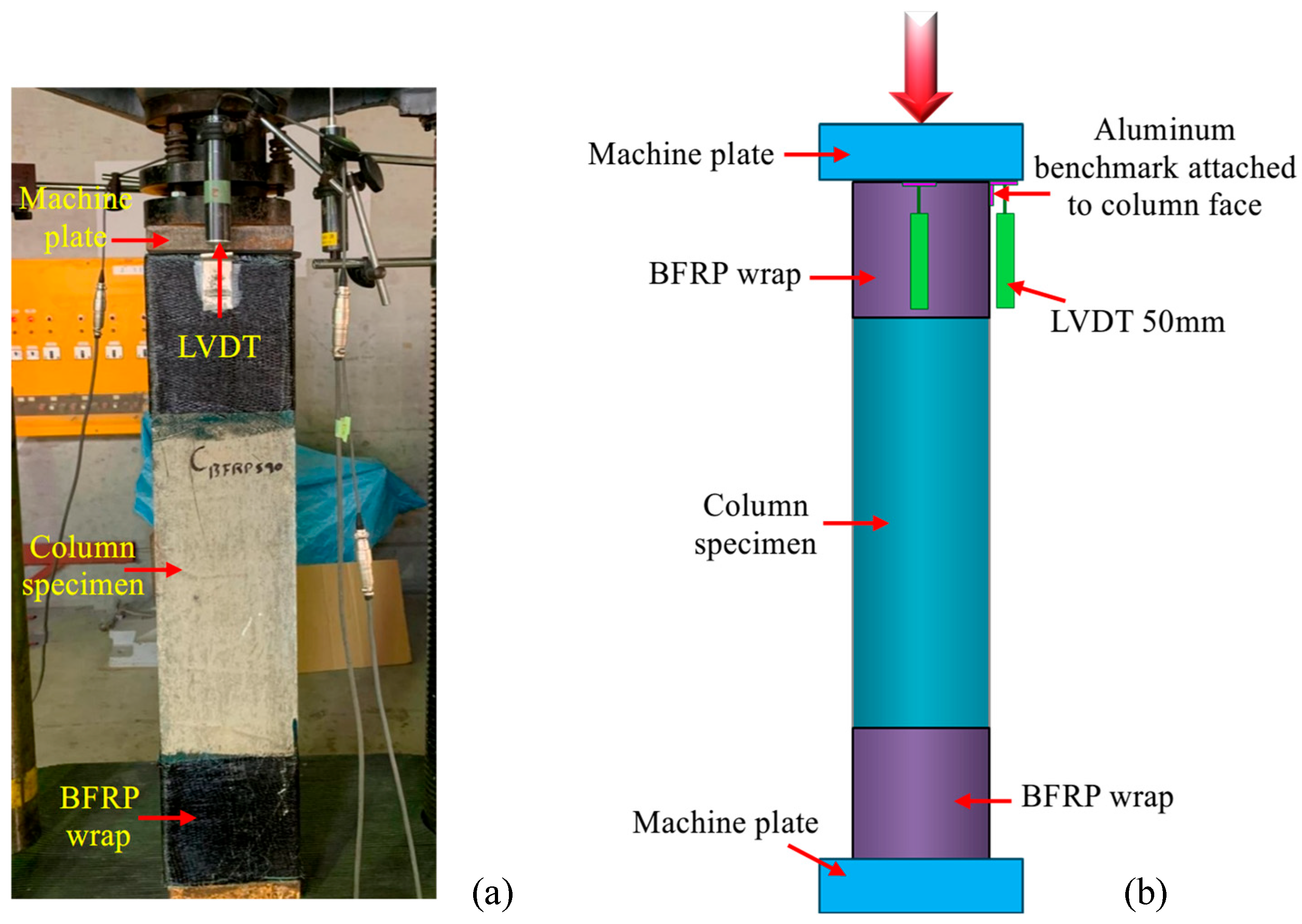
After curing, each specimen was instrumented to monitor axial load, strain, and displacement during testing. A Linear Variable Differential Transformer (LVDT) was mounted at the top of each column to measure axial deformation. Load was tracked using a calibrated load cell integrated into the hydraulic actuator of the compression machine. All instruments were connected to a digital data acquisition system for continuous monitoring and automatic recording. Crack patterns and surface spalling were visually inspected and documented during loading to correlate observed failures with instrument data.
This careful construction and instrumentation approach ensured consistent specimen quality and reliable data for evaluating the axial behavior of RC columns with different confinement systems.
2.4. Testing Procedure
All column specimens were tested under monotonic uniaxial compression using a servo-controlled hydraulic testing machine with a maximum load capacity of 2000 kN. The axial compression tests were conducted at room temperature, following the guidelines of ACI 363R [
38] and ASTM C39 [
33], with modifications appropriate for column testing. The primary objective was to evaluate the effect of confinement type and reinforcement layout on peak load capacity, stress–strain behavior, and failure modes. Each specimen was tested in an upright position between two steel loading platens. The base of the specimen was centered on the lower platen and aligned vertically using laser levels and plumb lines to ensure uniform loading. To ensure that failure occurred in the central test region rather than near the load application zones, the top and bottom 200 mm segments of each specimen were externally wrapped with a single layer of BFRP fabric, as shown in
Figure 4. This end confinement prevented premature crushing or cracking at the loading zones, thereby localizing failure within the unwrapped mid-span region.
The axial load was applied in displacement-controlled mode at a rate of 0.2 mm/min during the initial elastic stage. Once the column reached approximately 75% of its estimated peak capacity, the loading rate was reduced to 0.05 mm/min to capture detailed post-peak behavior. This approach allowed for a more accurate recording of deformation characteristics near and beyond peak load, particularly for specimens expected to exhibit ductile responses due to BFRP or hybrid confinement. Throughout the test, axial load, vertical displacement, and strain data were continuously recorded using the previously installed LVDTs, strain gauges, and load cell. Data was logged at intervals of 1 Hz to ensure a high-resolution stress–strain profile. Each test was continued until either (a) complete crushing and instability of the concrete core occurred, (b) rupture of the transverse reinforcement was observed, or (c) axial load dropped below 35% of the peak value, indicating significant structural degradation.
Visual observations of crack development, concrete spalling, and longitudinal bar buckling were carefully documented during the test. In particular, attention was given to the point and sequence of failure initiation in order to distinguish between different confinement systems. For specimens with BFRP ties, sudden rupture events were accompanied by audible snapping sounds, which were recorded and synchronized with load data to identify the timing of confinement failure. Upon completion of each test, the damaged specimen was examined in detail to identify internal failure mechanisms and to validate the instrumentation data. Selected columns were cut open to inspect the condition of the core concrete, the longitudinal reinforcement, and the residual integrity of the steel and BFRP ties. These post-test observations provided critical insight into the effectiveness of the different confinement configurations in controlling core degradation and resisting axial collapse. The standardized testing protocol ensured that each specimen was subjected to consistent loading and boundary conditions, allowing for reliable comparison across the various confinement strategies evaluated in this study.
3. Results and Discussion
This section presents and discusses the experimental results obtained from the axial compression tests conducted on the five RC column specimens. The primary objective is to evaluate and compare the influence of different confinement strategies, including steel-only ties, novel rectangular BFRP ties at two tie spacings, and hybrid steel–BFRP combinations, on the axial performance of square RC columns. The test results are analyzed to understand how confinement material and detailing affect key structural behaviors such as failure mode, axial load-carrying capacity, stress–strain characteristics, and overall confinement efficiency.
3.1. Failure Behavior of Column Specimens
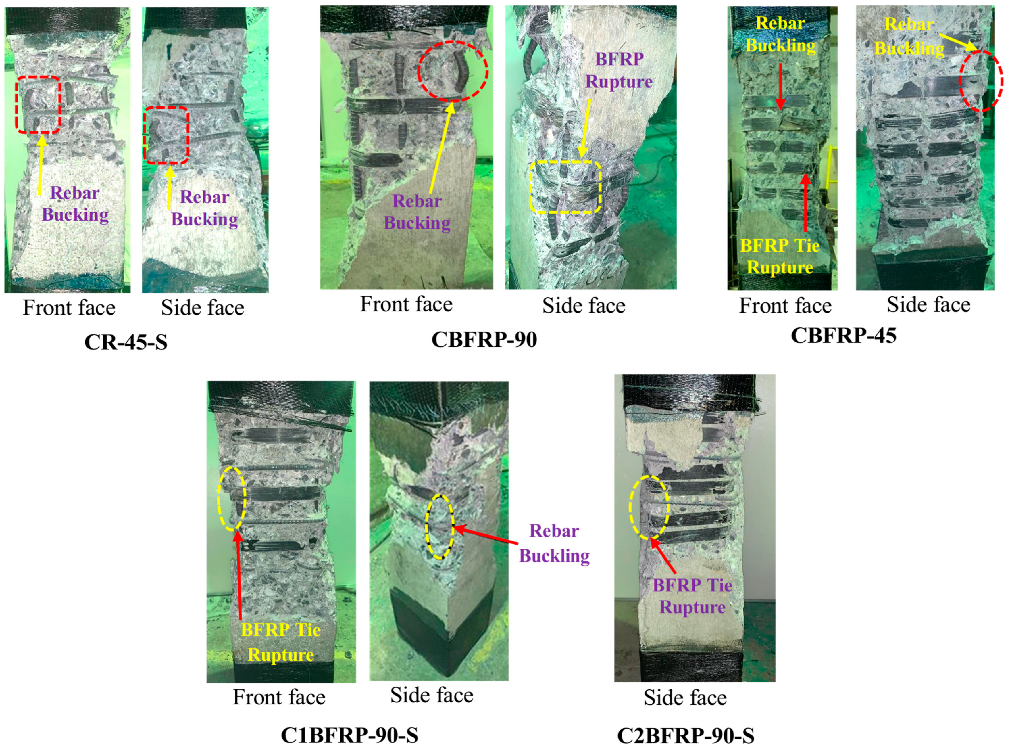
The failure behavior of the tested RC column specimens was closely observed to assess the influence of different confinement systems, namely conventional steel ties, novel BFRP ties at varying spacing, and hybrid steel–BFRP arrangements, on the structural integrity and ductility under monotonic axial loading. All specimens exhibited three distinct loading phases: (1) an elastic phase with linear load–displacement behavior until microcracking began, (2) a cracking and spalling phase marked by visible damage development up to the peak load, and (3) a post-peak degradation phase characterized by abrupt failure in the columns. However, the failure characteristics varied significantly depending on the confinement type, as shown in
Figure 5.
The reference specimen (CR-45-S), reinforced exclusively with closely spaced steel ties at 45 mm intervals, demonstrated high initial stiffness and the greatest peak load among all specimens. However, it exhibited a brittle failure mode shortly after peak strength. Vertical cracks developed along the mid-height as the load approached maximum capacity, followed by sudden spalling of the concrete cover. Failure was abrupt, characterized by pronounced buckling of the longitudinal steel bars and crushing of the core concrete. The loss of axial load capacity occurred rapidly, with limited post-peak deformation. This behavior reflects the classically brittle nature of heavily steel-confined columns under axial compression, where energy dissipation and ductility are limited despite the enhanced strength.
The two specimens confined solely using novel rectangular BFRP ties at 90 mm (CBFRP-90) and 45 mm (CBFRP-45) spacing exhibited more ductile and progressive failure mechanisms compared to the steel-only reference. In both specimens, initial cracking occurred at load levels similar to the control, but concrete cover spalling was delayed and more distributed along the column length. In CBFRP-90, the failure was initiated by the rupture of the BFRP ties near regions of bar buckling. The relatively wide tie spacing reduced lateral restraint, leading to earlier expansion of the core and visible bar instability. Although the post-peak load degradation was smoother than the steel-only case, confinement was only moderately effective. In contrast, CBFRP-45, which incorporated BFRP ties at half the spacing, demonstrated superior confinement action. Bar buckling and concrete crushing were significantly delayed, and the rupture of the FRP ties occurred progressively over a larger region. This specimen exhibited the highest post-peak axial strain among all columns, indicating excellent ductility. The distributed nature of damage, gradual degradation of load, and delayed rupture of the confinement elements confirmed the enhanced performance and improved failure resistance associated with tighter BFRP tie spacing. Overall, the BFRP-only specimens failed in a more controlled and ductile manner compared to the steel-confined specimen. The gradual tie rupture and extended deformation capacity are attributed to the BFRP’s ability to sustain tensile strains without yielding, even though their peak strength was marginally lower.
The hybrid specimens, C1BFRP-90-S with one BFRP tie between each pair of 90 mm-spaced steel ties and C2BFRP-90-S with two interspersed BFRP ties, exhibited the most favorable failure behavior. Both specimens achieved high peak loads close to that of the steel-only control, but with significantly improved post-peak ductility. In C1BFRP-90-S, concrete cover spalling initiated at high load levels but progressed gradually. The specimen sustained substantial axial deformation before failure, with visible buckling of longitudinal steel bars and sequential rupture of BFRP ties. The damage was well-distributed, and the column maintained structural integrity longer after peak load. C2BFRP-90-S, which had a higher volume of FRP reinforcement, showed similar failure characteristics but with even more delayed bar buckling and high post-peak deformation. The rupture of BFRP ties occurred gradually, and the steel ties contributed to restraining the core expansion, resulting in a highly synergistic confinement effect. In both hybrid specimens, the interaction between ductile steel yielding and gradual BFRP tie rupture created a stable post-peak response and avoided sudden collapse. These columns demonstrated superior confinement efficiency, effectively delaying core crushing and enhancing structural resilience.
The failure behavior of the tested columns highlights the critical role of confinement type and detailing. The steel-only specimen, despite its strength, suffered from brittle post-peak failure. The BFRP-only specimens exhibited significantly improved ductility and progressive failure, particularly with reduced tie spacing. The hybrid specimens offered the best overall performance, combining the strength of steel and the ductility of BFRP to deliver a well-balanced and reliable failure response. These findings support the viability of hybrid confinement systems in structural applications requiring both strength and deformation capacity.
3.2. Axial Load Capacity Analysis
The axial load capacity of RC columns is a critical measure of their structural performance under compressive loading. In this study, the axial load capacity of five RC columns with different confinement schemes was evaluated to quantify the influence of tie material and spacing on peak strength, as shown in
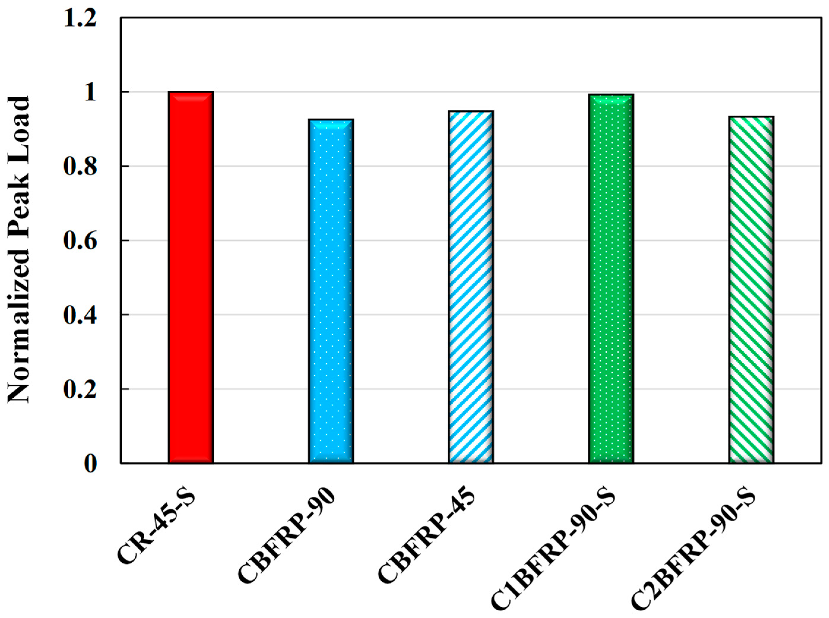
Figure 6. The tested specimens included: (1) a control column confined by closely spaced steel ties, (2) two columns confined solely with novel rectangular BFRP ties at different spacings, and (3) two columns employing a hybrid configuration combining steel and BFRP ties. The results provide insight into how confinement design affects the ultimate load-carrying capacity of square RC columns. To better illustrate these comparative results,
Figure 6 presents the peak axial load of each specimen normalized by the peak load of the steel-confined reference column CR-45-S. This normalized presentation highlights the relative gains or reductions in peak capacity across the different confinement schemes, making it easier to compare the performance effectiveness of each tie configuration.
The control specimen, CR-45-S, was confined using conventional 10 mm steel ties spaced at 45 mm. This configuration was designed to serve as a performance benchmark due to its high transverse reinforcement ratio (ρw = 2.14%). Under axial compression, CR-45-S attained the highest peak load among all specimens, reaching 1793.2 kN. The high confinement level provided by closely spaced steel ties effectively delayed the onset of internal damage and enhanced the core strength of the concrete. However, as noted in the failure analysis, this strength was accompanied by a brittle post-peak response and limited ductility. The high axial capacity observed in CR-45-S is consistent with established behavior of densely steel-confined concrete columns, where enhanced confinement pressure leads to an increase in the effective compressive strength of the core concrete (f′cc). Nonetheless, the trade-off between strength and ductility must be considered in seismic or deformation-controlled applications.
The axial load performance of BFRP-only specimens was significantly influenced by tie spacing. Specimen CBFRP-90, with BFRP ties spaced at 90 mm (
ρfw = 1.09%), achieved a peak axial load of 1659.8 kN, which is approximately 7.4% lower than that of the steel-confined control, as shown in
Table 4. This reduction is attributed to the lower stiffness and confinement pressure of the wider-spaced BFRP ties, which permitted earlier expansion of the core and bar buckling. In contrast, specimen CBFRP-45, which used BFRP ties at a reduced spacing of 45 mm (
ρfw = 2.18%), showed improved performance, reaching a peak axial load of 1699.0 kN. This corresponds to only a 5.3% decrease relative to the control specimen. The enhanced strength in CBFRP-45 reflects the beneficial effect of reduced tie spacing, which increases lateral restraint and delays the degradation of the concrete core under axial loading. Although both BFRP-only columns had slightly lower peak loads than the steel-only reference, they demonstrated comparable confinement effectiveness, especially when tie spacing was minimized. The ability of the novel rectangular BFRP ties to sustain tensile loads and provide confinement was confirmed, particularly in CBFRP-45, where the peak strength approached that of the conventional steel-reinforced column.
The hybrid confinement specimens provided further insight into the synergistic potential of combining steel and BFRP ties. Specimen C1BFRP-90-S, with steel ties at 90 mm spacing and one BFRP tie interspersed between each steel tie (ρw = 1.07%, ρfw = 1.09%), achieved a peak axial load of 1780.0 kN, only 0.7% lower than the steel-only control. This result indicates that the inclusion of BFRP ties effectively compensated for the wider steel tie spacing, maintaining comparable axial strength while also improving ductility, as discussed earlier. Specimen C2BFRP-90-S, which used the same steel configuration but included two BFRP ties between each pair of steel ties (ρfw = 2.18%), attained a slightly lower peak load of 1673.0 kN. While this value is about 6.7% lower than that of CR-45-S, it still represents a strong performance given the reduced amount of steel used. The marginal decrease in strength may be attributed to the increased deformability of the FRP elements and the greater reliance on their confinement effect. Importantly, both hybrid specimens achieved peak loads comparable to or exceeding those of the BFRP-only columns. The results demonstrate that even with wider steel tie spacing, the addition of BFRP ties can restore and, in some cases, enhance the confinement effect, allowing for a more balanced trade-off between material usage, strength, and deformation capacity.
The results confirm that while steel ties provide the highest axial strength, they offer limited post-peak deformation capacity. In contrast, BFRP-only confinement can achieve comparable strength levels, particularly when tie spacing is reduced to enhance lateral restraint. Hybrid confinement systems present a balanced solution by maintaining high load capacity while significantly improving ductility and reducing the dependency on traditional steel reinforcement. These findings validate the structural viability of the novel rectangular BFRP ties and demonstrate that hybrid steel–BFRP configurations can effectively replicate or even surpass the load-bearing performance of conventional steel confinement, particularly when detailed with appropriate spacing and reinforcement ratios.
3.3. Axial Stress–Strain Behavior
The axial stress–strain behavior of confined RC columns provides critical insights into their deformation capacity, ductility, and energy dissipation characteristics under compressive loading. In this study, stress–strain curves were developed for all five specimens based on axial load and displacement measurements recorded during testing. Axial displacement was measured using LVDTs installed at mid-height to capture the full axial shortening of the specimen under loading. The axial strain values reported in this study were calculated by dividing the measured displacement by the clear height of the column. The curves allow for a direct comparison of the confinement effects provided by different reinforcement schemes, namely conventional steel ties, innovative BFRP ties at two spacing intervals, and hybrid steel–BFRP systems.
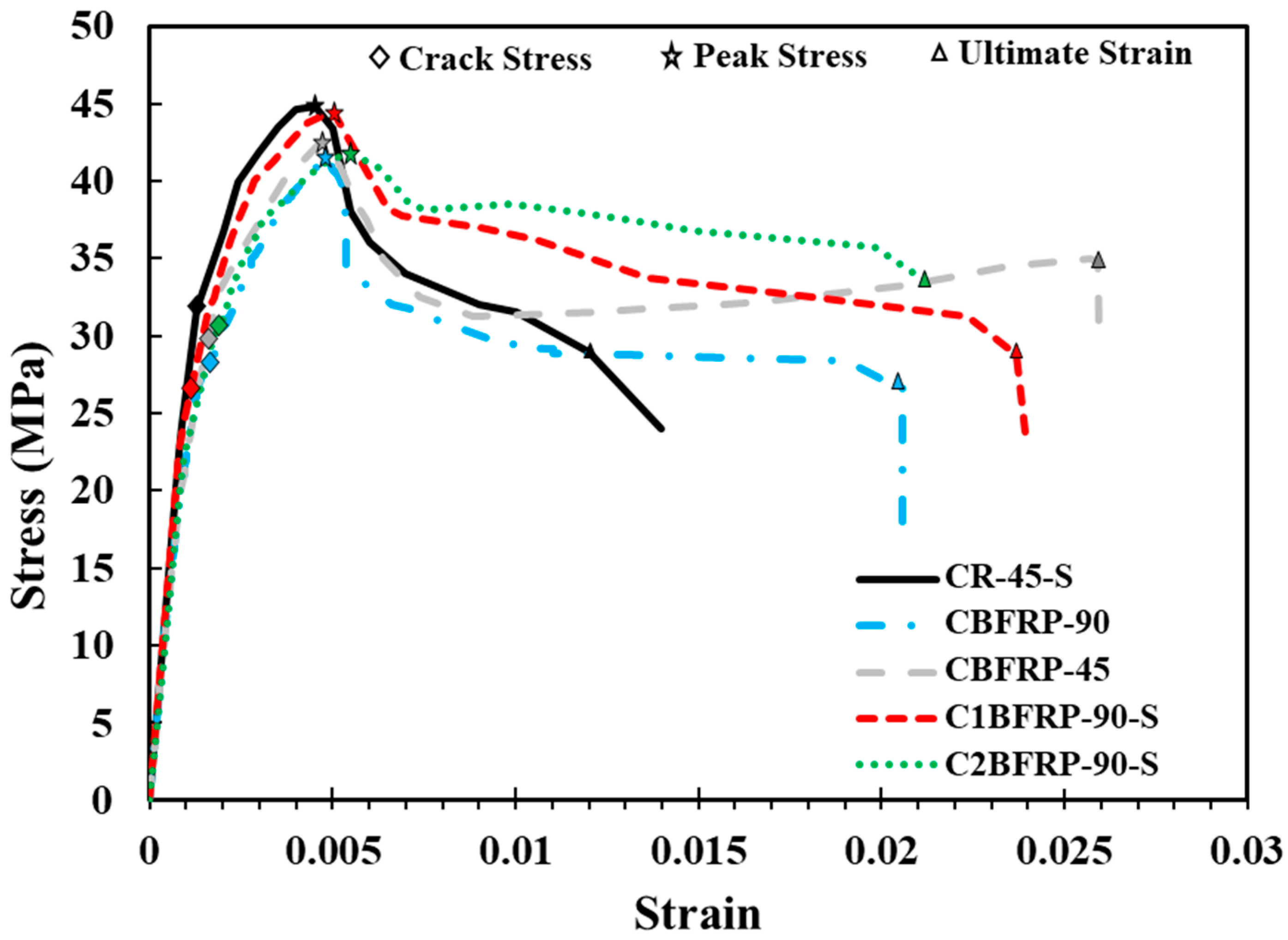
Figure 7 illustrates the complete axial stress–strain profiles of the tested columns. These profiles were analyzed to identify key behavioral parameters including initial stiffness, peak strength, post-peak softening, and ultimate strain capacity. All specimens underwent three distinct phases during axial loading: an initial elastic response, a cracking and spalling stage, and a post-peak softening phase. The boundaries between these phases were identified based on noticeable changes in slope and inflection points on the stress–strain curves, such as the first deviation from linearity indicating cracking onset, and the peak load point marking the transition to the softening phase.
Figure 7 shows these phase boundaries clearly annotated for each specimen. This staged behavior reflects the progressive development of internal cracking, concrete spalling, and core crushing under increasing axial stress. The influence of confinement type and tie spacing on the shape and extent of the stress–strain response is discussed in detail below.
The steel-only specimen (CR-45-S) exhibited a typical tri-linear stress–strain response. The initial portion of the curve demonstrated a steep, linear slope indicative of high stiffness and elastic behavior. As the stress approached the peak value (corresponding to 1793.2 kN), the curve transitioned to a short nonlinear segment followed by a sharp post-peak drop. The most prominent characteristic of CR-45-S’s response was the abrupt strength degradation after peak stress, with minimal deformation capacity beyond the maximum stress point. The axial strain at peak stress (
εc) was 0.45%, while the ultimate strain (
εcu) was limited to 1.12%, as shown in
Table 5. This rapid post-peak decline is associated with brittle failure mechanisms, including bar buckling and core crushing, and reflects limited energy absorption capability. While the specimen achieved the highest confined concrete strength (
f′cc = 44.83 MPa), the lack of ductility significantly reduces its effectiveness in applications requiring deformability, such as seismic design.
The axial stress–strain responses of the BFRP-only confined columns displayed considerably more gradual and ductile behavior. Both specimens experienced a relatively linear elastic phase followed by a broader transition zone leading to peak stress, and a smooth post-peak descending branch. For CBFRP-90, the stress–strain curve peaked at an axial load of 1659.8 kN, with a peak strain (εc) of 0.476% and an ultimate strain (εcu) of 2.05%. The post-peak behavior was characterized by sustained axial deformation, with moderate strength degradation. This reflects the ability of the BFRP ties to restrain lateral expansion and delay core failure, even with wider tie spacing. In contrast, CBFRP-45 showed the most ductile behavior among all specimens. The stress–strain curve reached a peak at 1699.0 kN (f′cc = 42.50 MPa), with an ultimate strain of 2.66%, the highest recorded in the test series. The reduced spacing of the BFRP ties significantly enhanced the lateral confinement pressure, leading to delayed bar buckling and distributed cracking. The post-peak decline was gradual and extended, indicating effective energy dissipation and deformation capacity. These results underscore the importance of tie spacing in BFRP confinement. Closer spacing led to more uniform stress distribution and enhanced confinement effectiveness, as evidenced by the flatter and more extended stress–strain curve of CBFRP-45.
The hybrid-confined specimens combined the yield capacity of steel with the high tensile strength and strain capacity of BFRP ties, resulting in a highly favorable and structurally significant stress–strain behavior. Both specimens exhibited controlled transitions through the elastic, peak, and post-peak phases. C1BFRP-90-S achieved a peak load of 1780.0 kN, with a peak strain of 0.50% and an ultimate strain of 2.24%. The post-peak curve declined gradually, reflecting the delayed rupture of BFRP ties and the progressive yielding of steel ties. The response demonstrated high energy dissipation and a stable deformation pattern. C2BFRP-90-S, which incorporated a higher BFRP reinforcement ratio, exhibited a similar stress–strain profile. The peak load of 1673.0 kN was associated with a peak strain of 0.50% and an ultimate strain of 2.12%. The gentle post-peak slopes in both hybrids indicate that the combination of steel’s ductile yielding and BFRP’s high tensile strain capacity provides a composite confinement mechanism that enhances structural resilience.
This synergy maintains lateral pressure on the concrete core even after the steel ties yield, allowing the BFRP ties to continue restraining expansion until rupture occurs. As a result, the hybrid columns display stable, gradual load degradation instead of sudden collapse, which is especially critical for seismic and impact-resistant design where energy dissipation and deformation capacity are vital. The balance between strength and deformability makes hybrid confinement especially suitable for applications requiring structural resilience under extreme loading conditions.
Figure 8 presents a clear contrast between the confinement schemes. The steel-only column achieved the highest stress but exhibited the sharpest decline post-peak. The BFRP-only columns had slightly reduced peak strengths but sustained large strains, especially at reduced tie spacing. The hybrid specimens effectively combined the advantages of both materials, demonstrating that well-designed hybrid confinement can deliver robust peak capacity along with improved ductility and controlled failure modes—qualities that are indispensable for safe structural performance under seismic or dynamic loads.
In summary, the axial stress–strain behavior of the tested columns indicates that while steel-only confinement provides high strength, it lacks ductility. BFRP-only confinement, especially with reduced tie spacing, significantly improves strain capacity and enables a more gradual failure mode. Most importantly, the hybrid confinement system delivers the most balanced performance, combining the reliable yielding behavior of steel with the sustained tensile strength of BFRP ties to achieve a stable post-peak response that reduces the risk of brittle collapse. This makes hybrid confinement a highly resilient and effective strategy for critical structural applications.
3.4. Confinement Efficiency Evaluation
The efficiency of transverse confinement in RC columns is a critical determinant of both compressive strength and ductility. In this study, the confinement efficiency of various reinforcement schemes, including conventional steel ties, innovative BFRP ties at two spacing intervals, and hybrid steel–BFRP systems, was assessed by analyzing the enhancement of concrete strength due to confinement. This evaluation is based primarily on the confinement effectiveness ratio, defined as the ratio between the confined concrete strength (
f′cc) and the unconfined concrete strength (
fco), i.e.:
This parameter provides a normalized measure of how effectively each transverse reinforcement configuration improved the axial strength of the concrete core beyond its unconfined capacity.
The steel-only confined specimen, CR-45-S, achieved the highest confined concrete strength (
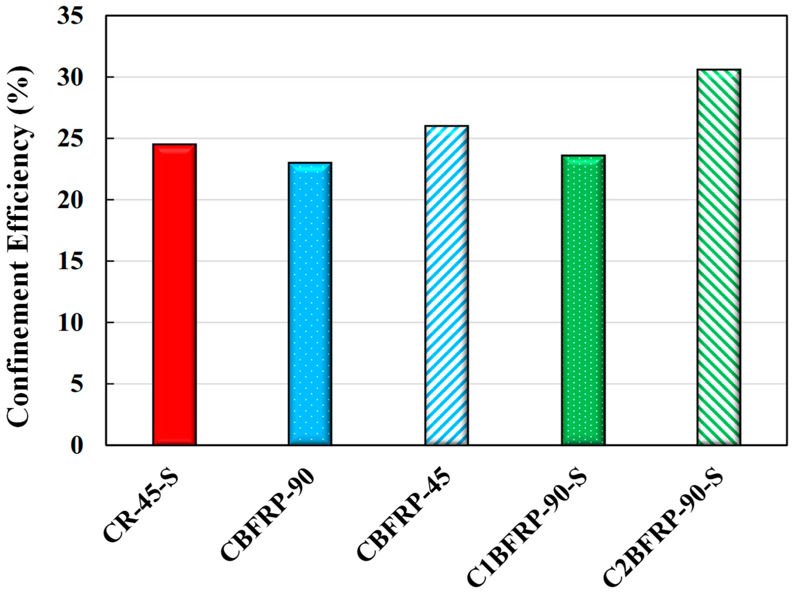
f′cc = 44.83 MPa) among all tested columns. Given an average unconfined concrete strength of approximately 36 MPa, this yielded a confinement effectiveness ratio of 1.245, representing a 24.5% increase in compressive strength due to steel confinement, as shown in
Figure 9. This result confirms the well-established performance of closely spaced steel ties in improving the compressive behavior of RC columns. However, as shown in earlier sections, this increase in strength was accompanied by limited ductility and abrupt post-peak degradation, indicating that high confinement effectiveness does not necessarily imply high deformation capacity.
The confinement effectiveness of the BFRP-only specimens varied significantly with tie spacing. Specimen CBFRP-90, using BFRP ties at a 90 mm spacing, reached a confined concrete strength of 41.50 MPa, resulting in an effectiveness ratio of 1.230. Although slightly lower than the steel-confined column, this demonstrates that even widely spaced BFRP ties can enhance axial strength by over 23%. More notably, specimen CBFRP-45, with tighter BFRP tie spacing, achieved a confined concrete strength of 42.50 MPa, corresponding to an effectiveness ratio of 1.260, nearly matching the steel-confined column. This 26% improvement highlights the critical role of tie spacing in achieving effective lateral restraint. The improved confinement led to delayed core crushing, reduced bar buckling, and superior post-peak performance. The results confirm that novel rectangular BFRP ties, particularly when placed closely, are capable of delivering confinement efficiency on par with traditional steel ties. Additionally, they offer advantages in terms of corrosion resistance and reduced weight.
Hybrid confinement schemes, which combine the yielding behavior of steel ties with the high tensile strength and corrosion resistance of BFRP ties, demonstrated strong performance in terms of both strength and ductility. Specimen C1BFRP-90-S, containing one BFRP tie between every two steel ties, achieved a confined concrete strength of 44.50 MPa, resulting in an effectiveness ratio of 1.236. This is only marginally lower than that of the steel-only specimen but was achieved with a lower volume of steel and enhanced ductility. Specimen C2BFRP-90-S, which included two BFRP ties between each pair of steel ties, recorded a confined concrete strength of 41.80 MPa, yielding the highest effectiveness ratio of 1.306 among all specimens. This 30.6% improvement over the unconfined strength suggests that the combined action of densely arranged BFRP ties and moderately spaced steel ties creates a highly effective and synergistic confinement mechanism. The increase in BFRP tie volume in this configuration played a decisive role in enhancing lateral pressure, delaying core expansion, and extending axial strain capacity. These findings demonstrate that hybrid confinement systems can outperform individual confinement schemes by leveraging the distinct advantages of both reinforcement types. Even when steel ties are spaced at wider intervals, the introduction of intermediate BFRP ties can substantially enhance the confinement effect and result in higher strength and deformation capacity.
The comparative analysis confirms that all confinement systems significantly enhanced the strength of concrete compared to the unconfined case. BFRP ties proved highly effective, especially with reduced spacing, achieving performance levels close to those of steel ties. Hybrid configurations consistently demonstrated high confinement efficiency, with the C2BFRP-90-S specimen delivering the best overall results. Confinement effectiveness was closely linked to ductility, particularly in BFRP and hybrid systems, which showed high ultimate strain capacities. These findings underscore the potential of the novel BFRP ties, both as standalone confinement elements and within hybrid systems, to match or surpass the performance of traditional steel ties. In addition to improving ductility and post-peak behavior, these systems offer enhanced durability and corrosion resistance. For structural design, hybrid reinforcement provides a practical means of optimizing material use, reducing steel congestion, and achieving tailored performance in terms of strength, ductility, and long-term durability, especially in harsh environmental conditions.
3.5. Limitations and Recommendations for Future Work
This study represents a preliminary experimental investigation into the axial compression behavior of square RC columns confined by novel rectangular BFRP ties and hybrid steel–BFRP confinement systems. Due to practical constraints, only a single specimen was tested for each confinement configuration. While this provides valuable initial insights into comparative performance, the lack of replicate specimens means that the natural variability of concrete properties, tie fabrication, and experimental scatter could not be quantified statistically. The findings should therefore be interpreted as indicative rather than definitive. Future experimental work should expand the test matrix with multiple replicates for each configuration to improve statistical reliability and strengthen the basis for design recommendations.
Furthermore, the present study focused solely on experimental testing under monotonic axial loading. It did not incorporate the development or validation of analytical or numerical models capable of predicting the mechanical behavior of RC columns confined by BFRP or hybrid ties. Such models are crucial for extending the experimental results to a wider range of geometries, material properties, and loading conditions. Future work should also focus on developing robust numerical models or simplified analytical models, building on existing numerical frameworks available in the literature [
39,
40,
41,
42]. This would allow parametric studies on key variables such as tie spacing, confinement ratio, and concrete strength, and would provide engineers with practical tools to predict the behavior of BFRP and hybrid-confined RC columns under various loading conditions. Such modeling efforts are essential for translating experimental observations into design charts or code provisions for real-world implementation.
The promising confinement efficiency demonstrated by the novel BFRP and hybrid steel–BFRP tie systems also has potential implications for future design code provisions. Current international design standards, such as ACI 318 [
43] and Eurocode 2 [
44], primarily base transverse confinement requirements on conventional steel stirrups and hoops, with explicit assumptions about yielding, plastic hinging, and ductility under seismic loading. The high tensile strength retention and improved strain capacity observed in this study suggest that continuous filament-wound BFRP ties could be considered a viable internal confinement alternative or supplement, especially for structures exposed to aggressive environments where corrosion of steel ties is a major durability concern. However, to translate this efficiency into design code rules, further research is needed to develop reliable stress–strain models, appropriate confinement effectiveness factors, and clear detailing guidelines that account for the linear elastic–brittle nature of FRP materials. Adoption into codes would also require validating the system’s performance under combined axial–flexural and cyclic loading conditions to ensure it meets ductility demands in seismic design regions.
To this end, future work should also investigate the performance of these confinement systems under low-cycle fatigue or seismic cyclic loading to confirm their ductility and energy dissipation capacity under realistic earthquake conditions. In addition, the promising experimental results allow for some preliminary design recommendations. Based on the observed performance, designers are advised to limit BFRP tie spacing to 45 mm or less to achieve comparable confinement effectiveness to closely spaced steel ties. For hybrid configurations, a wider steel tie spacing (e.g., 90 mm) can be used if supplemented by one or more intermediate BFRP ties to maintain sufficient lateral pressure and ductility. While these spacing guidelines provide a useful starting point, final design should account for concrete strength, expected loading conditions, and durability requirements. Developing detailed design models and practical guidelines for calculating the required confinement ratio, effective lateral pressure, and tie arrangement will be a valuable focus for future research.
Finally, the promising results of the proposed BFRP and hybrid systems indicate the need for further investigation into their long-term durability under environmental exposure as well as their behavior under cyclic and combined axial–flexural loading conditions typical of real-world seismic or bridge column applications. Addressing these aspects in future studies will help validate the practical feasibility of replacing or supplementing conventional steel ties with corrosion-resistant BFRP solutions in durability-critical and seismic regions.
