Article

Thermal Degradation and Microstructural Evolution of Geopolymer-Based UHPC with Silica Fume and Quartz Powder

by
Raghda A. Elhefny
1,
Mohamed Abdellatief
2,*,
Walid E. Elemam
1 and
Ahmed M. Tahwia
1
1
Department of Structural Engineering, Faculty of Engineering, Mansoura University, Mansoura 35516, Egypt
2
Department of Civil Engineering, Higher Future Institute of Engineering and Technology in Mansoura, Mansoura 35516, Egypt
*
Author to whom correspondence should be addressed.
Infrastructures 2025, 10(8), 192; https://doi.org/10.3390/infrastructures10080192
Submission received: 7 May 2025 / Revised: 15 July 2025 / Accepted: 21 July 2025 / Published: 22 July 2025

Abstract

The durability and fire resilience of concrete structures are increasingly critical in modern construction, particularly under elevated-temperature exposure. With this context, the current study explores the thermal and microstructural characteristics of geopolymer-based ultra-high-performance concrete (G-UHPC) incorporating quartz powder (QP) and silica fume (SF) after exposure to elevated temperatures. SF was used at 15% and 30% to partially replace the precursor material, while QP was used at 25%, 30%, and 35% as a partial replacement for fine sand. The prepared specimens were exposed to 200 °C, 400 °C, and 800 °C, followed by air cooling. Mechanical strength tests were conducted to evaluate compressive and flexural strengths, as well as failure patterns. Microstructural changes due to thermal exposure were assessed using scanning electron microscopy (SEM) and energy-dispersive X-ray spectroscopy (EDS). Among the prepared mixtures, the 30SF35QP mixture exhibited the highest compressive strength (156.0 MPa), followed by the 15SF35QP mix (146.83 MPa). The experimental results demonstrated that G-UHPC underwent varying levels of thermal degradation across the 200–800 °C range yet displayed excellent resistance to thermal spalling. At 200 °C, compressive strength increased due to enhanced geopolymerization, with the control mix showing a 29.8% increase. However, significant strength reductions were observed at 800 °C, where the control mix retained only 30.8% (32.0 MPa) and the 30SF25QP mixture retained 28% (38.0 MPa) of their original strengths. Despite increased porosity and cracking at 800 °C, the 30SF35QP mixture exhibited superior strength retention due to its denser matrix and reduced voids. The EDS results confirmed improved gel stability in the 30% SF mixtures, as evidenced by higher silicon content. These findings suggest that optimizing SF and QP content significantly enhances the fire resistance and structural integrity of G-UHPC, providing practical insights for the design of sustainable, high-performance concrete structures in fire-prone environments.

1. Introduction

Annually, the building industry consumes an average of 0.26 billion metric tons of Portland cement (PC), as reported by global statistics [1,2,3]. Limestone, the primary raw material for PC production, will face a significant depletion risk within the next two to four decades [4]. Moreover, producing one metric ton of PC releases approximately an equivalent amount of CO2, posing a substantial environmental threat [5,6]. On the other hand, PC-based ultra-high-performance concrete (PC-UHPC), a composite material rich in PC, is celebrated for its exceptional compressive strength, durability, and toughness [7,8,9]. It is widely utilized in advanced structural projects, including long-lasting bridges, towering skyscrapers, and nuclear facilities exposed to harsh conditions [10,11,12]. However, despite its strengths, PC-UHPC has limitations, particularly due to its high PC content—ranging from 800 to 1150 kg/m3, nearly triple that of conventional concrete—resulting in elevated CO2 emissions [13,14]. Abdellatief et al. [8] reported the successful formulation of a UHPC matrix with a reduced binder content of 650 kg/m3, achieving a 30% reduction in carbon emissions. Likewise, Wu et al. [15] determined that substituting 20% and 40% of PC with fly ash and slag, respectively, significantly enhanced the ultimate flexural strengths of PC-UHPCs. Therefore, increasing awareness of the CO2 emissions generated during PC manufacturing has fueled a push to eliminate PC usage in concrete production. In response, geopolymer-based ultra-high-performance concrete (G-UHPC) has emerged, utilizing geopolymer as a binder instead of PC.
Geopolymers are inorganic binding agents created through a chemical reaction involving aluminosilicate materials, often derived from industrial by-products, offering a lower environmental footprint than PC [16,17,18]. While earlier research predominantly explored normal-strength geopolymer concrete (GPC) [19,20], recent attention has shifted toward high-strength GPC [21], though studies on its fire resistance remain scarce. In this context, Tahwia et al. [22] investigated the impact of high temperatures on the properties of G-UHPC that incorporates waste glass and ceramic as partial aggregates. The research specifically examined compressive strength and microstructural changes in G-UHPC subjected to temperatures ranging from 200 °C to 800 °C. Notably, G-UHPC containing waste glass retained a remarkable 41.0 MPa of residual compressive strength after exposure to 800 °C, while G-UHPC with waste ceramic exhibited only 22 MPa. Additionally, Xie et al. [23] investigated the effects of cellulose nanofiber (CNF) on the mechanical and thermal properties of G-UHPC under different curing conditions. This study found that CNF improved residual compressive strength after exposure to 200–400 °C. Microscopic analyses (XRD, FT-IR, and TGA) confirmed that CNF promoted geopolymerization and C-(A)-S-H gel formation, enhancing both mechanical properties and thermal stability. Additionally, Abdellatief et al. [24] conducted a series of experiments to evaluate the behavior of G-UHPC incorporating fine ceramic waste (FCW) as a partial replacement of fine aggregate. Their findings demonstrated that G-UHPC with FCW exhibited accelerated setting time, reduced slump, and a moderate decline in mechanical properties at higher replacement levels. However, the residual strength of FCW-based G-UHPC improved significantly after exposure to elevated temperatures, particularly at 700 °C. Thermogravimetric analysis (TGA) indicated greater thermal stability up to 650 °C, while microscopic analysis revealed fewer microcracks and enhanced structural integrity compared to control specimens. Fadi et al. [25] also investigated the enhancement of G-UHPC by incorporating nano-silica and polypropylene fibers under high-temperature resistance. The results indicated that specimens retained compressive strength to some extent at 250 °C but experienced a drastic decline at 750 °C. This highlights the need for other materials that can enhance both thermal stability and mechanical performance.
In this context, quartz powder (QP), derived from natural quartz through processes like sorting, crushing, and washing, has emerged as a valuable additive due to its high purity and low iron content [26,27]. Tavares et al. [28] demonstrated that substituting 20% of PC with silica fume (SF) or 20 µm of QP in cementitious composites reduced the heat of hydration at early ages compared to the control paste, though long-term effects on strength development were observed for up to several months of curing. Similarly, Lin et al. [29] explored a PC-QP mortar, revealing that QP primarily contributed to the dilution and nucleation effects during cement hydration without altering the hydration products. These properties suggest that QP could help to counter the thermal deterioration seen in G-UHPC at high temperatures. Additionally, in PC-UHPC, SF significantly enhances both mechanical and long-term properties due to its dense packing effect [26]. Earlier studies have also noted that incorporating 10–15% of SF improves the rheological properties of PC-UHPC [8,27]. In the context of GPC, while multiple studies have indicated that adding SF boosts strength development, it often reduces workability [28,30,31]. Wetzel et al. [32] suggested that an optimal amount of SF can enhance both the workability and compressive strength of G-UHPC. They examined the effects of partially replacing ground granulated blast furnace slag (GGBFS) with SF in the production of G-UHPC while maintaining a constant metakaolin content. Their findings revealed that substituting 12.5% of GGBFS with SF resulted in an optimal compressive strength of 178.6 MPa; however, an increase to 15% SF led to a reduction in strength. Meanwhile, SF plays a complementary role, particularly in PC-UHPC, where its dense packing effect boosts both mechanical strength and long-term durability. However, in G-UHPC, the picture is more complex. While SF often increases strength, it tends to reduce workability.

2. Aim of This Study

Despite the expanding research on geopolymer-based ultra-high-performance concrete (G-UHPC) and its notable thermal resilience compared to conventional Portland cement-based UHPC (PC-UHPC), critical knowledge gaps remain, particularly concerning its microstructural evolution and thermal degradation when exposed to elevated temperatures. Existing studies have primarily focused on the mechanical enhancement of G-UHPC through the addition of SF, as demonstrated by [32], who achieved optimal compressive strength with 12.5% SF substitution, and Althoey et al. [33], who reported improved tensile and flexural strengths with nano-silica. However, these investigations largely address ambient conditions or limited temperature ranges, neglecting the systematic evaluation of thermal degradation mechanisms and microstructural evolution at elevated temperatures (e.g., 200 °C to 800 °C). Furthermore, while SF is recognized for enhancing matrix density and strength in both PC-UHPC and G-UHPC, and QP has been shown to reduce shrinkage and act as a micro-filler in PC-based systems, their combined influence on the geopolymerization process, gel stability (e.g., C-A-S-H and N-A-S-H), and post-fire residual properties remains underexplored. Therefore, this study aims to address these gaps by investigating the microstructural and thermal characteristics of G-UHPC incorporating SF and QP as partial replacements for precursor materials and sand, respectively. We also aim to subject G-UHPC specimens to elevated temperatures (200 °C, 400 °C, and 800 °C) followed by natural cooling and analyze their mechanical properties (compressive and flexural strengths) and microstructural changes via scanning electron microscopy (SEM) and energy dispersive X-ray spectroscopy (EDS).

3. Materials and Methods
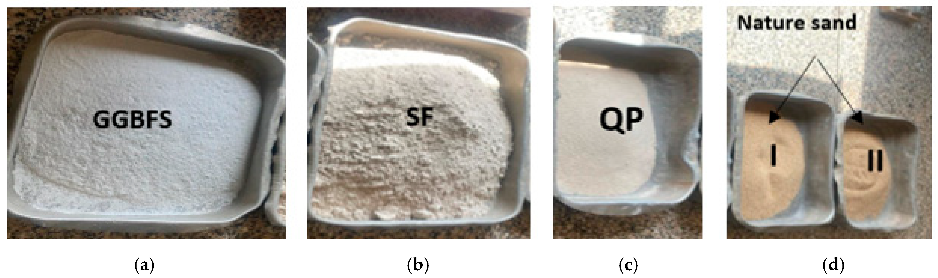
3.1. Materials

The components employed in this investigation consist of GGBFS, SF, natural fine sand categorized into two small particle levels, type I (0.6–0.8) mm and type II (0.15–0.30) mm, and QP, as shown in Figure 1. GGBFS, with a specific gravity of 2.90 and a specific surface area of 390 m2/kg, was employed as the primary binder material. SF, which has a specific gravity of 2.29 and an extensive specific surface area of 27,000 m2/kg with a silica content up to 92.18%, was used as a partial replacement for GGBFS and following ASTM C618-19 [34] and ASTM C1240-05 [35]. SF was used as the secondary precursor. To eliminate the micro-particulate voids in the geopolymer paste, improve packing density, and ultimately enhance durability and strength by producing secondary hydrates through the pozzolanic reaction, as illustrated in Figure 2, G-UHPCs require a pozzolanic material that contains micro-sized particles. Thus, un-densified amorphous SF containing approximately 90–95% SiO2 was provided and used in compliance with ASTM C1240. The chemical compositions of GGBFS and SF are presented in Table 1, while their particle size distributions are illustrated in Figure 3.
Natural fine sand with a specific gravity of 2.65, and following ASTM C33 [36], served as the fine aggregate, with a maximum particle size of 0.8 mm. The proportion of aggregates used in this investigation is detailed in Table 1, where class A, B, and C aggregates denote 25%, 30%, and 35% substitution of natural aggregates, respectively. The GGBFS, SF, and QP specimens were analyzed using X-ray fluorescence (XRF) spectroscopy to determine their chemical compositions, with the results presented in Table 2. The alkali activator in the experiment was composed of sodium silicate (SS), sodium hydroxide (NaOH) reagent (98% purity), and deionized water. The sodium silicate, supplied by Sika Materials Co., Ltd., El Obour, Egypt, was a liquid solution containing 9.57% Na2O and 28.06% SiO2 with a modulus of 3.30. A 20% solid superplasticizer (SP) based on polycarboxylate was employed, with a water-reducing effectiveness of over 30%.

3.2. Mixture Proportions and Specimen Preparation

Prior to usage, the aggregates were first moistened and then dried to attain a saturated surface that was of a dry state, thus preventing workability loss and enhancing bonding efficacy. Before casting, the sodium hydroxide crystals were submerged in deionized water the previous day to obtain the desired alkali concentration and mitigate excessive heat generation. At normal temperature, sodium hydroxide was combined with a sodium silicate solution to create a mixture subsequently employed in the preparation of G-UHPC mixes. The mixtures were formulated using a liquid-binder dosage of 0.30, a sodium hydroxide dosage of 16 molarity, and a silicate-to-hydroxide concentration of 2.5.
Table 3 indicates a detailed composition of binders for each mixture. The combinations were made by substituting SF for GGBFS at proportions of 0%, 15%, and 30%, alongside varying ratios of QP (25%, 30%, and 35%) as a partial substitute for natural sand. The dry components, including GGBFS, SF, QP, and sand, were gradually introduced and blended to create a consistent dry mixture. The materials were first dry mixed, and then 50% of the activator solution was added gently; then, the remaining solution with SP was added. Mixing continued until a homogenous mixture was obtained. All mixtures were designed and adjusted to maintain adequate workability, with flow diameters ranging between 180 mm and 210 mm, measured using the standard flow table test. The prepared mixtures were cast in metal molds in three layers and vibrated using a table vibrator to remove air bubbles. Following the casting process, after 24 h, the specimens were demolded and heated up to 80 °C for 24 h and left to cure at room temperature.

3.3. Test Methods

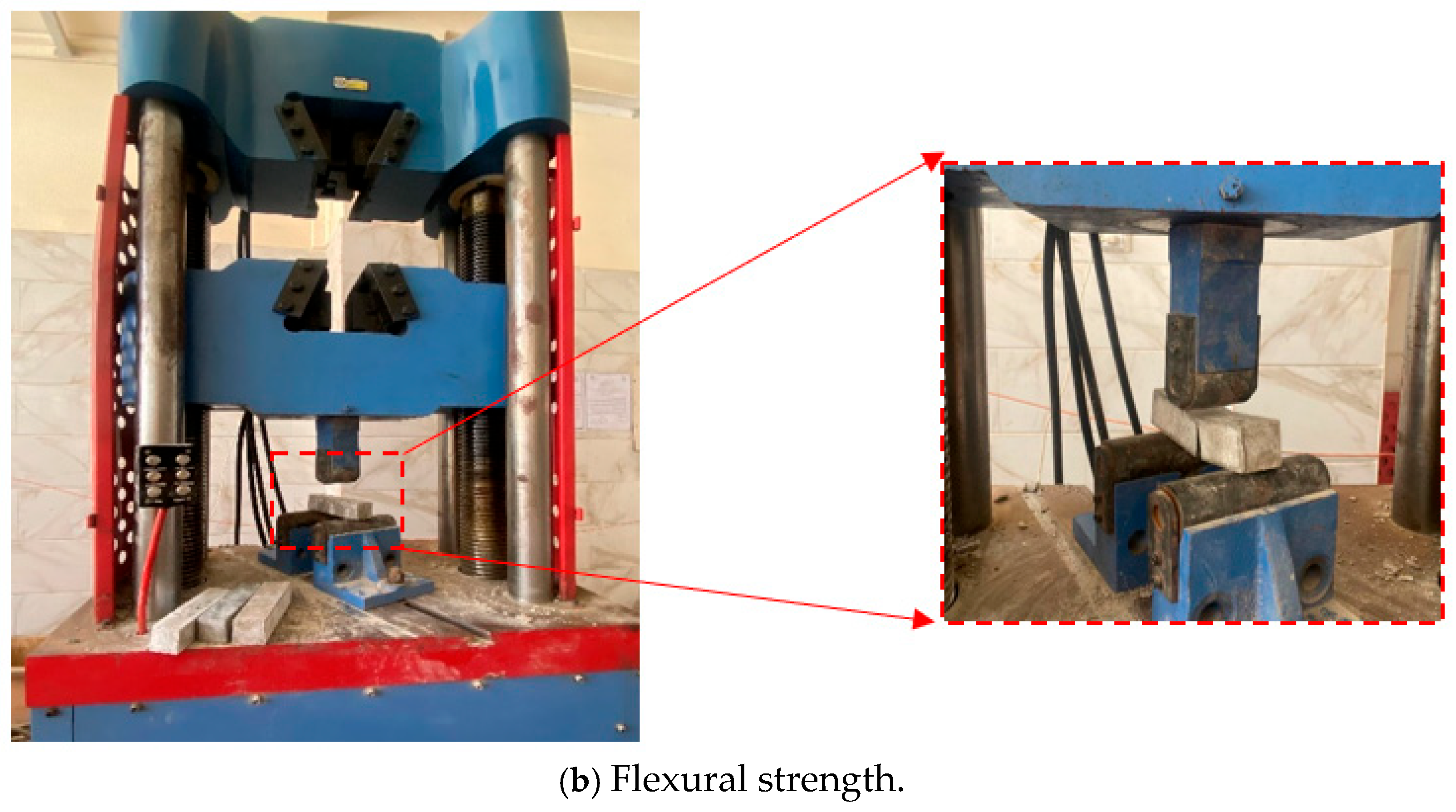
3.3.1. Testing of Flexural and Compressive Strengths

An evaluation of the compression capacity of the mixtures was carried out on days 7, 28, and 56 of casting using 50 × 50 × 50 mm cube specimens. For this, we utilized a compressive testing machine featuring a capacity of 300 tons in accordance with ASTMC109-C109M [37], as shown in Figure 4a. The mixes were prepared and allowed to cure at ambient temperature, with a relative humidity of 72% and temperatures ranging from 27 to 31 °C. Three specimens of each batch were tested. As demonstrated in the ASTMC78/C78M [38] test, prismatic specimens sized 40 × 40 × 160 mm were used to evaluate the flexural strength of the mixed specimens using third-point loading, as shown in Figure 4b.

3.3.2. Thermal Treatment and Specimen Preparation

The prepared specimens were subjected to thermal treatment using an electric furnace capable of reaching 1200 °C, as illustrated in Figure 5a, with targeted temperatures set at 200 °C, 400 °C, and 800 °C. Before heating, the specimens underwent a 28-day curing period. To minimize thermal gradients between the interior and exterior of the G-UHPC, a controlled heating rate of 10 °C/min was applied. This gradual heating promoted steady moisture release within the matrix, enhancing its stability and lowering the risk of spalling. Once the designated temperature was achieved, it was held constant for 1.5 h to ensure uniform heat distribution throughout the specimen, as shown in Figure 5. The thermal exposure procedure is shown in Figure 5, and it should be noted that the cooling process we used was naturally cooling down, as presented in the schematic in Figure 5c. The specimen dimensions (50 × 50 × 50 mm) were specifically chosen to optimize heat transfer, reducing the potential for significant internal temperature variations. Compared to larger G-UHPC components, these smaller cross-sections enabled more consistent heating. After thermal exposure, the specimens underwent natural cooling by being placed in a chamber for 24 h until they returned to ambient temperature. This approach mimicked the gradual cooling of G-UHPC in real-world conditions, after which the mechanical and microstructural properties were evaluated.

3.3.3. Microscopic Investigations

The morphology and microstructure of powdered G-UHPC specimens were examined using a Jeol-JSME6510LV scanning electron microscope (SEM). For the SEM analysis, specimens were prepared by sectioning a flaky solid measuring 1 cm in length and 1 cm in breadth from the test block. Each specimen was coated with a thin layer of gold to enhance electron conduction and secured in a copper holder. Imaging was performed with a secondary electron detector operating at 15 kV. Additionally, SEM coupled with energy dispersive spectroscopy (EDS) was employed to investigate the microstructure of both the starting materials and the resulting geopolymer matrices. This microstructural analysis was conducted using an FEI Quanta 450 FEG focused ion beam system equipped with an EDAX Genesis EDS, providing detailed insights into the compositional and structural characteristics of the specimens.

4. Results and Discussion

4.1. Compressive Strength

This study evaluates the compressive strength of G-UHPC mixtures incorporating varying proportions of SF, GGBFS, and QP as substitutes. Liu et al. [39] demonstrated that incorporating steel fibers and SF (5–30%) in G-UHPC improved the mechanical and fracture properties, with 20–30% SF enhancing performance the most, though 10% SF reduced mechanical strength despite increasing flowability. Thus, the following subsections analyze the compressive strength variations based on SF and QP replacement levels and curing duration in the current study, with the results illustrated in Table 4.

4.1.1. The Impact of Silica Fume

The results in Figure 6 and Figure 7 demonstrate that the SF content significantly enhances the compressive strength of G-UHPC, irrespective of QP presence. At 28 days, mixes with 15% (Figure 6) and 30% SF (Figure 7) combined with 25% QP exhibited strength increases of 17.5% and 31.95%, respectively, relative to the control mix (M0). For 30% QP, compressive strength rose by 25.82% (15% SF) and 44.96% (30% SF) compared to 25% QP mixes. Similarly, mixes with 35% QP showed increases of 31.4% (15% SF) and 56.23% (30% SF) over their 15% SF counterparts [39]. The peak compressive strength was recorded at 156 MPa for the 30SF35QP mix at 56 days, demonstrating the synergy between high SF and QP levels. This strength enhancement is primarily due to SF’s space-filling effect, which densifies the microstructure [40]. Wu et al. [41] corroborate this, reporting improved compressive strength with SF replacements up to 20%. However, Karthikeyan and Dhinakaran [42] noted a peak at 10% SF, with a decline at 15%, contrasting with our findings. At 35% SF, the activator generates higher concentrations of (SiO4)4−, boosting reactivity and yielding maximum strength [43]. Compared to the control (M0), the 35% QP mix with 30% SF increased strength by approximately 20%, despite potential microstructural weakening at higher replacement levels due to reduced particle density and weaker interparticle bonding [44]. SF reacts with calcium hydroxide from hydration to form calcium silicate hydrate (C-S-H), filling voids and refining the pore structure, as explained in Figure 2 [44]. Its fine particles and large surface area reduce the water or paste layer thickness around particles, enhancing gel formation via geopolymer hydration and pozzolanic reactions [45]. Liu et al. [39] found that 30% SF maximized compressive strength, while 20% SF optimized elastic modulus, suggesting that higher SF content could offset reduced steel fiber use without compromising performance. Unlike Aisheh et al. [46], who observed a strength drop beyond 5% SF, our study shows consistent gains up to 30% SF, peaking at 156 MPa with 35% QP. This disparity may reflect differences in the mix design or curing conditions. The superior surface-area-to-mass ratio of SF compared to GGBFS increases packing density, reducing water demand for hydration and limiting space for new hydration products [47]. This denser matrix enhances compressive strength, aligning with the observed trends [48].

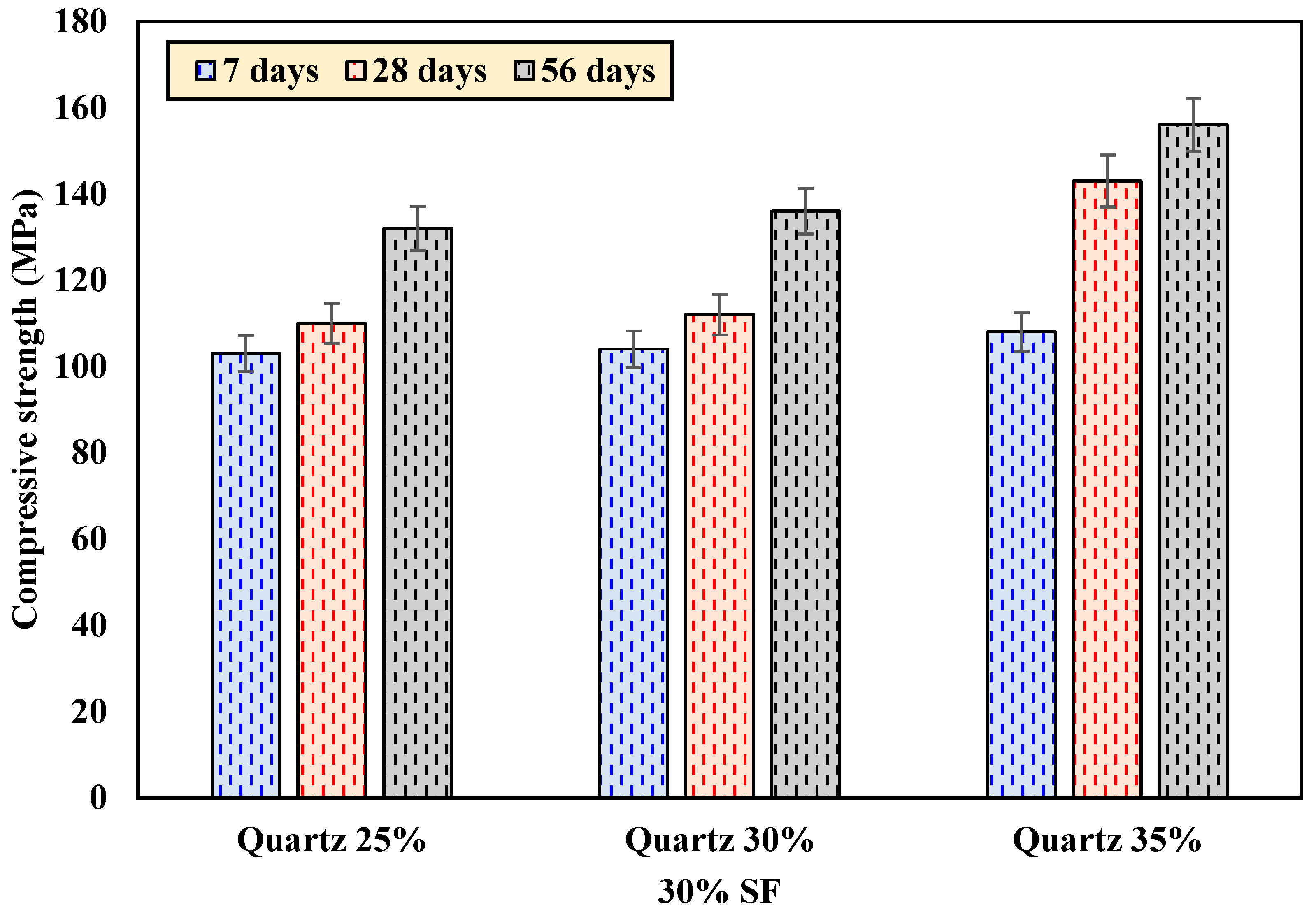
4.1.2. The Effect of Quartz Powder

Figure 6 and Figure 7 illustrate the significant influence of QP on G-UHPC compressive strength. Mixes with 15% SF showed strength increases of 24%, 29.8%, and 40% at QP levels of 25%, 30%, and 35%, respectively, compared to M0. For 30% SF, the increases were 27.9%, 30.76%, and 50% at the same QP levels. The 30SF35QP mix exhibited the highest strength (156 MPa at 56 days), outperforming lower QP variants. This enhancement stems from QP’s smaller particle size, which improves packing density and strengthens the matrix. Jiao et al. [49] reported similar findings, noting enhanced compressive strength with glass sand as an aggregate in G-UHPC. Another study [50] found that 20% and 30% quartz increased strength by 33.7% and 34.6%, respectively, with a peak of 152 MPa at 40% quartz and 2% steel fibers. In our study, the 7-day strengths ranged from 65% to 74% of the 28-day values, resembling cement-based concrete behavior. While elevated curing temperatures (40–60 °C) enhance geopolymer strength, Zhang [51] observed comparable 28-day strengths between high- and ambient-temperature curing.

4.2. Flexural Strength

The flexural strength of G-UHPC mixtures was assessed using a third-point loading test on prismatic specimens (40 × 40 × 160 mm) after 56 days of curing, as presented in Figure 8. The control mix (M0), lacking SF, exhibited a flexural strength of 9.82 MPa. In contrast, mixes with 15% SF and 35% QP (15SF35QP) and 30% SF and 35% QP (30SF35QP) achieved significantly higher flexural strengths of 16.0 MPa and 20.3 MPa, respectively. The incorporation of SF, particularly at 30%, markedly improved bending strength compared to the SF-free mix. This enhancement is attributed to the pozzolanic reactivity of SF, which refines the pore structure, strengthens the interfacial transition zone, and increases the composite’s resistance to bending stresses, as discussed later. Additionally, the replacement of slag with SF contributed to the densification of the binder matrix, improving microstructural integrity [52]. These findings are consistent with Liu et al. [39], who observed a comparable flexural strength of ~23 MPa for a mix with 30% SF substitution. The highest flexural strength of 20.3 MPa in the 30SF35QP mix highlights the synergistic benefit of combined high SF and QP contents in enhancing G-UHPC’s flexural performance. Nevertheless, it is important to note that the results are based on specific mix proportions and specimen dimensions. Broader mix ranges and larger-scale tests are required to validate the generalizability of these flexural performance improvements under field-like conditions.

4.3. Thermal Performance

4.3.1. Physical Appearance

Visual inspection of the G-UHPC specimens revealed thermophysical changes, including color alterations, surface cracking, and spalling, following exposure to elevated temperatures. Figure 9 illustrates the appearance of the control mix (M0), as well as mixes with 15% SF and 35% QP (15SF35QP) and 30% SF and 35% QP (30SF35QP), after heating to 800 °C. No significant changes in color or surface integrity were observed across all specimens when the temperature increased from 27 °C to 200 °C, with all specimens retaining a uniform grayish tint. Between 200 °C and 400 °C, the control mix and the SF-containing mixes maintained their shape but darkened slightly to a deeper gray shade, indicating the onset of thermal effects. At 800 °C, a substantial reduction in water content led to a noticeable lightening of the specimens’ color, shifting from a darker gray to a lighter hue across all of the mixes [53]. Surface cracks became evident in the control mix (M0) and other specimens at this temperature, with the control mix exhibiting more pronounced cracking and spalling, as seen in Figure 9a. In contrast, the addition of QP in the 15SF35QP and 30SF35QP mixes reduced the propensity for cracking, with the 30SF35QP mix showing the least surface deterioration (Figure 9c). This improved thermal stability is attributed to the enhanced microstructural integrity provided by QP, which mitigates crack formation under high temperatures.

4.3.2. Compressive Strength After High-Temperature Exposure

The compressive strength of G-UHPC mixes was evaluated after exposure to elevated temperatures (27 °C, 200 °C, 400 °C, and 800 °C) at 56 days of curing. Figure 10 illustrates the variation in compressive strength for mixes with (a) 15% SF and (b) 30% SF, each with varying QP contents. At 200 °C, the control mix (M0) exhibited a residual compressive strength of 135 MPa, a 29.8% increase compared to its ambient strength of 104 MPa. Similarly, mixes with 15% SF (15SF25QP, 15SF30QP, 15SF35QP) showed increases of 11.8%, 6.5%, and 3.5%, respectively, while mixes with 30% SF (30SF25QP, 30SF30QP, 30SF35QP) increased by 18.2%, 16.2%, and 2.6%, respectively, compared to their 27 °C strengths. This initial strength enhancement at 200 °C is attributed to the accelerated geopolymerization and densification of the matrix [54]. At 400 °C, the compressive strength of all mixes decreased relative to their 200 °C values. The control mix retained 91.3% of its ambient strength (95 MPa), while 15% SF mixes experienced reductions of 20.5% (15SF25QP), 22.2% (15SF30QP), and 24.2% (15SF35QP). For 30% SF mixes, the reductions were 13.6% (30SF25QP), 15.4% (30SF30QP), and 25.0% (30SF35QP). At 800 °C, a significant decline in compressive strength was observed across all mixes due to thermal degradation and pore structure development [55]. The control mix retained only 30.8% of its ambient strength (32 MPa), while 15% SF mixes retained 27.7% (15SF25QP), 25.7% (15SF30QP), and 23.8% (15SF35QP). In contrast, 30% SF mixes showed better retention, with 28.8% (30SF25QP), 25.7% (30SF30QP), and 24.4% (30SF35QP), aligning with the finding of 28% retention for 30SF25QP outlined in the Abstract.
Figure 11 presents the residual compressive strength as a percentage of ambient (27 °C) strength. At 800 °C, the control mix retained 30.8% of its original strength, while 15% SF mixes retained 27.7% to 23.8%, and 30% SF mixes retained 28.8% to 24.4%. The higher residual strength in 30% SF mixes is attributed to the enhanced microstructural stability provided by SF, which fills voids and promotes the formation of additional C-A-S-H gel through geopolymerization [55]. The incorporation of QP further mitigated cracking, with 30SF35QP showing the least surface deterioration (as observed in Figure 9), contributing to better strength retention compared to the control mix. Yu et al. [56] reported that steel fibers enhance the residual compressive strength of geopolymer concrete at elevated temperatures, particularly between 300 °C and 500 °C, by reducing strength degradation under thermal stress. Although our mixes did not include fibers, the 30% SF mixes demonstrated superior performance at 800 °C compared to 15% SF mixes, suggesting that higher SF content compensates for the absence of fibers to some extent. Additionally, the lower cracking and absence of spalling in SF- and QP-containing mixes indicate improved thermal resistance compared to the control mix.

4.4. Microscopic Analysis Before Heating

The microstructure of G-UHPC specimens before exposure to elevated temperatures was examined using SE, as shown in Figure 12. All specimens exhibited a dense microstructure, which contributes to their exceptional compressive strengths at ambient conditions (27 °C). The control mix achieved a compressive strength of 104 MPa at 56 days (Table 4), while mixes with 15% SF and varying QP content (15SF25QP, 15SF30QP, 15SF35QP) reached 126.56 MPa, 139 MPa, and 146.83 MPa, respectively. The SEM analysis revealed minimal unreacted material in all specimens, indicating a high degree of reaction between GGBFS and other raw materials. The control mix (Figure 12a) displayed a relatively dense matrix but with some visible unreacted particles and minor voids, correlating with its lower compressive strength compared to SF-containing mixes. In contrast, the 15SF25QP specimen (Figure 12b) showed a more compact structure with fewer voids, attributed to the pozzolanic activity of SF, which fills pores and enhances matrix density. This densification aligns with its higher compressive strength (126.56 MPa) compared to M0 [21,25,57]. The 15SF35QP specimen (Figure 12c) exhibited an even denser microstructure with a smoother surface, reflecting the combined effect of 15% SF and 35% QP. The fine QP particles act as a filler, further reducing porosity, which corresponds to its compressive strength of 146.83 MPa, the highest among 15% SF mixes. For 30% SF mixes, the 30SF25QP (Figure 12d) and 30SF35QP (Figure 12e) specimens displayed highly compact matrices with minimal unreacted slag, consistent with their compressive strengths of 132 MPa and 156 MPa, respectively. The dense microstructure is attributed to the formation of geopolymer gels, primarily calcium aluminosilicate hydrate (C-A-S-H) and sodium aluminosilicate hydrate (N-A-S-H) [21,25]. The C-A-S-H gel, resulting from the reaction of SF with slag, enhances matrix density by filling voids, while N-A-S-H, formed from the aluminosilicate precursors, contributes to the overall binding strength. The presence of highly crystalline hydro silicates and hydro aluminates, detected alongside these gels, further supports the observed mechanical performance.
The energy-dispersive X-ray spectroscopy (EDS) analysis of G-UHPC mixes before exposure to elevated temperatures, as shown in Figure 13, reveals variations in elemental composition across the M0, 15SF25QP, 15SF35QP, 30SF25QP, and 30SF30QP specimens. The M0 (Figure 13a) exhibits prominent peaks for calcium (Ca), silicon (Si), and aluminum (Al), indicative of calcium aluminosilicate hydrate (C-A-S-H) formation, with minor iron (Fe) presence likely from unreacted slag [21,58]. The 15SF25QP (Figure 13b) and 15SF35QP (Figure 13c) specimens show increased Si peaks due to the addition of silica fume (SF), reflecting enhanced C-A-S-H gel formation, which correlates with their higher compressive strengths (126.56 MPa and 146.83 MPa, respectively) compared to M0 (104 MPa). For 30% SF mixes, 30SF25QP (Figure 13d) and 30SF30QP (Figure 13e) display even higher Si and reduced Ca peaks, suggesting a greater proportion of sodium aluminosilicate hydrate (N-A-S-H) alongside C-A-S-H, aligning with their superior strengths (132 MPa and 136 MPa). The presence of sodium (Na) and potassium (K) in all mixes confirms the geopolymerization process, with 30% SF mixes showing a more balanced elemental distribution, contributing to their enhanced microstructural density (Section 4.3).

4.5. Microscopic Analysis After Heating

The microstructure of the G-UHPC specimens after exposure to 800 °C at 56 days of curing was analyzed using SEM and EDS, as shown in Figure 14. Micrographs of four specimens—control mix (M0), 15SF25QP, 15SF35QP, 30SF25QP, and 30SF35QP—revealed significant changes compared to their pre-heating state (Section 4.5). The control mix (Figure 14a) exhibited a highly porous microstructure with numerous voids and cracks, reflecting the decomposition of calcium aluminosilicate hydrate (C-A-S-H) gels and the release of water vapor during heating. This increased porosity aligns with its drastic compressive strength reduction to 32 MPa at 800 °C, a 69.2% loss from its ambient strength of 104 MPa (Table 4). The 15SF25QP and 15SF35QP specimens (Figure 14b,c) showed fewer voids and cracks compared to M0, attributed to the stabilizing effect of SF and QP. The 15SF35QP mix displayed a slightly denser matrix with semi-crystalline morphology, correlating with its residual compressive strength of 35 MPa (23.8% retention). Similarly, the 30SF25QP and 30SF35QP specimens (Figure 14d,e) exhibited greater compactness and fewer pores than M0, with 30SF35QP showing the least microstructural disruption. This enhanced thermal stability corresponds to their higher residual strengths of 38 MPa (28.8% retention for 30SF25QP) and 38 MPa (24.4% retention for 30SF35QP). The reduced cracking in SF- and QP-containing mixes is consistent with visual observations (Figure 10), confirming the protective role of these additives at high temperatures. Wan et al. [59] noted that G-UHPC indicates that small cracks may have formed in the tested specimens during compression testing, as these specimens originated from crushed specimens. Microcracks result from detrimental chemical reactions within the pores, as geopolymers release alkalis into the pore solution, which could contribute to strength [60]. Cai et al. [30] revealed that alkali-activated ternary binders formulated with slag, fly ash, and SF using a simplex centroid design exhibited strength gains at 200 °C in mixes with over 30% fly ash, attributed to the heat-induced densification of potassium–aluminosilicate–hydrate (K-A-S-H) gels, though higher SF fractions led to greater mechanical degradation at 600 °C and above due to extensive dehydration cracking, the formation of akermanite and anorthite phases, and increased susceptibility to softening in fly ash-rich mixes at 800 °C.
The EDS analysis revealed changes in the elemental composition of the geopolymer matrix post-heating. The control mix (M0) showed a high calcium-to-silicon (Ca/Si) ratio, indicating residual C-A-S-H decomposition products, with reduced sodium (Na) and aluminum (Al) peaks due to the breakdown of sodium aluminosilicate hydrate (N-A-S-H) gels. In contrast, 15SF25QP and 15SF35QP exhibited increased Si and Al peaks, suggesting the partial retention of N-A-S-H gels, while 30SF25QP and 30SF35QP displayed the highest Si content, reflecting greater stability of their geopolymer matrix. The increased porosity and microstructural disruption at 800 °C, driven by volumetric expansion, water vapor release, and gel decomposition, explain the significant strength loss observed across all mixes [61]. Despite the thermal degradation, G-UHPC specimens demonstrated resilience in sulfate solutions, attributed to the incorporation of SF with slag. The fine SF particles fill voids, enhancing the microstructure through geopolymerization, even after high-temperature exposure. The improved microstructural stability in SF- and QP-containing mixes, even after 800 °C exposure, suggests their potential for applications requiring combined thermal and chemical durability.

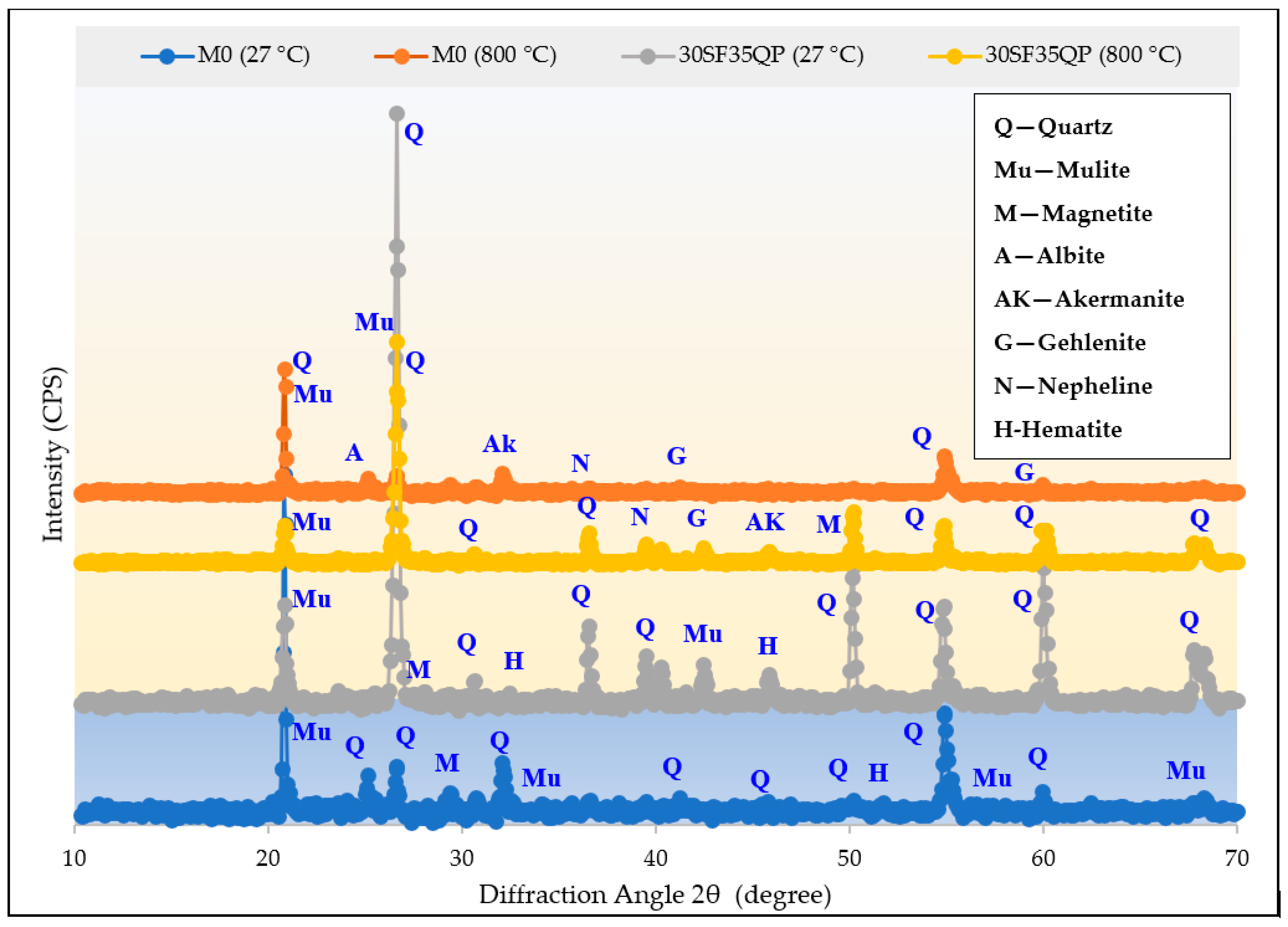
4.6. XRD Analysis Before and After Heating

The XRD patterns of the G-UHPC samples before and after exposure to 800 °C are shown in Figure 15. At ambient temperature (27 °C), both the control mix (M0) and optimal mix (30SF35QP) contained similar features of a broad amorphous hump between 20° and 35° 2θ characteristic of C-A-S-H and N-A-S-H gels and small crystalline peaks associated with quartz (Q), mullite (Mu), and hematite (H). The amorphous broad peaks indicate that geopolymer gel products dominated the matrix. Exposure to 800 °C resulted in an observable phase change. For M0, the intensity of the amorphous hump significantly lessened and crystalline phases of mullite (Mu), albite (A), akermanite (Ak), and gehlenite (G) were generated, signifying some decomposition of the gel products and regrowth into crystalline aluminosilicate phases. The formation of nepheline (N) and hematite (H) indicates thermal reconstitution that is in agreement with the strength loss, increased porosity, and cracking seen in the SEM.
For the 30SF35QP mixture, although there was again a common transformation of phases at 800 °C, the corresponding XRD pattern had more amorphous content and slightly sharper quartz peaks with less intense secondary crystalline phases. This suggests high material structure stability possibly due to densification and inhibiting silica fume and quartz powder effects. The changes in phases could also indicate less development of akermanite and nepheline phases compared to M0. These dynamics explain the retention of thermal resistance and strength for the 30SF35QP mixture. Thus, the evidence shows that silica fume and quartz powder do improve mechanical performance at ambient conditions, and their inclusion actively mitigates thermal degradation through stabilization of the geopolymer matrix at elevated temperatures.

4.7. Further Discussion

At ambient conditions (27 °C), G-UHPC exhibits negligible mass loss with no thermal degradation, achieving compressive strengths ranging from 104 MPa for the control mix to 156 MPa for the 30SF35QP mix (Table 5). SEM analysis (Section 4.5) reveals a dense microstructure with minimal unreacted particles, driven by C-A-S-H and N-A-S-H gels, which contribute to high strength and durability, aligning with [21,25,30,62], who noted enhanced matrix density with SF and nano-silica additives. At 200 °C, minimal mass loss (1–3%) occurs due to free water evaporation, as reported in previous studies [24], while residual compressive strength increases across all mixes. This enhancement, attributed to accelerated geopolymerization and matrix densification, is supported by SEM images showing a compact structure with no visible cracking, consistent with [22], who observed strength gains at 200 °C due to improved gel formation. At 400 °C, moderate mass loss (5–10%) emerges from bound water evaporation and the onset of gel decomposition, reducing compressive strength to 91.3% retention for M0 (95 MPa), 75.6% for 15SF35QP (111 MPa), and 75.0% for 30SF35QP (117 MPa). The SEM analysis reveals minor voids and cracks due to dehydration and thermal stress, yet the material remains serviceable under reduced loading, as noted by [23,24,25]; they reported significant load-bearing capacity up to 500 °C with SF additives. At 800 °C, significant mass loss (15–20%) occurs due to intense dehydration, the breakdown of aluminosilicate bonds, and decomposition of C-A-S-H and N-A-S-H gels, leading to a drastic strength drop—M0 retains 30.8% (32 MPa) and 30SF35QP retains 24.4% (38 MPa) of their ambient strengths. The SEM images show extensive porosity and cracking, particularly in M0, while 30SF35QP exhibits greater compactness and fewer voids, explaining its better strength retention (24.4–28.8% for 30% SF mixes). The EDS analysis indicates a higher Ca/Si ratio and reduced Na/Al peaks, confirming gel breakdown, a trend consistent with [22,24,32], who reported a 70–80% strength loss at 800 °C, and Althoey et al. [25,33], who noted that sodium-based activators mitigate microstructural damage to some extent.
On the other hand, when subjected to elevated temperatures, G-UHPC demonstrates a complex interplay of chemical transformations and physical changes that collectively impact its mechanical strength. Research indicates that the residual strength of geopolymer systems after high-temperature exposure is governed by two competing mechanisms: matrix densification, which enhances strength, and crack formation, which leads to strength loss [19,22,30,61]. However, the strength evolution mechanism in G-UHPC is more complex due to the combined influence of SF and QP on its thermal behavior. To indicate the specific roles of SF and QP in the high-temperature performance of geopolymer systems, this study compares the physicochemical transformations and their competing effects on the thermal behavior of G-UHPC with varying SF and QP contents. Conceptual models illustrating the degradation mechanisms of G-UHPC mixtures under elevated temperatures are presented in Figure 16.
Prior to high-temperature exposure, the G-UHPC sample displays a porous structure containing numerous unreacted GGBFS particles and residual water. In contrast, G-UHPC mixtures with an optimal amount of SF exhibit a denser matrix with reduced porosity, fewer unreacted GGBFS particles, and noticeable microcracks. This densification is primarily due to SF addition, which significantly enhances the activation process, resulting in a compact matrix with lower ductility. Upon exposure to 200 °C, the porous structure of G-UHPC allows for the release of water as internal thermal stress increases, preserving the matrix with only minor microcracks. However, in G-UHPC with optimal SF, the dense structure and lower pore connectivity cause existing microcracks to widen and lengthen, with independent cracks starting to link through the interfacial transition zone (ITZ), as seen in SEM images (Figure 14). Meanwhile, the elevated temperature promotes further geopolymerization in both 30SF25QP and 30SF35QP samples, a process verified by EDS analysis and retained strength. This further geopolymerization is critical in preventing spalling, a common issue in OPC binders under high temperatures. It achieves this by consuming free water, thereby reducing internal thermal stress, and by forming additional geopolymer gel that fills cracks, pores, and voids, ultimately reinforcing the matrix. Consequently, the crack formation caused by free water evaporation is offset by this enhanced geopolymerization, leading to an overall strength increase at this temperature.
Between 200 °C and 400 °C, the geopolymer binder in G-UHPC maintains good stability, with further geopolymerization keeping the dominant process at up to 400 °C. Additionally, the binder phase demonstrates rearrangement, forming macropores due to binder shrinkage and sintering at 400 °C, though no decomposition of the binder gel is observed. For instance, Cai et al. [30] highlighted that G-UHPC matrices can undergo densification at moderate temperatures (e.g., 200–400 °C) due to continued geopolymerization, which enhances mechanical strength. However, at higher temperatures, the same study noted that thermal stresses and dehydration lead to crack formation, resulting in significant strength loss. In G-UHPC, however, the dehydration and decomposition of the hybrid gel exert a significant influence on the matrix. This effect stems from the incorporation of SF and QP, which enables calcium to substitute sodium in the N-A-S-H gel, forming a less thermally stable hybrid N-C-A-S-H gel [22,30]. During this temperature range, complete evaporation of moisture within the matrix occurs, accompanied by heightened internal thermal stress, leading to the widening and lengthening of pre-existing cracks (Figure 16). Simultaneously, the depolymerization of the hybrid gel results in the formation of numerous small, evenly distributed cracks that widen over time. The rapid increase in crack numbers introduces more micro-defects into the G-UHPC matrix, while the decomposition of the binder creates large voids. These processes contribute to an increase in macropore and megapore fractions, as well as greater pore interconnection, as confirmed by the SEM analysis. Between 400 °C and 800 °C, G-UHPC reveals simultaneous recrystallization and viscous sintering processes, as explained by [30,63,64]. According to XRD analysis from our prior studies [19,58], new crystalline phases such as nepheline, akermanite, and gehlenite emerge during this stage. Notably, the formation of porous crystalline phases like nepheline negatively impacts matrix compactness, weakening the gel skeleton, as indicated by a significant reduction in skeleton density, as shown in Figure 14. Concurrently, viscous sintering utilizes the remaining GGBFS and SF to fill small pores and fine cracks, leading to a noticeable shift from a rough to a smooth texture. However, in the control mix (M0), larger voids and cracks persist compared to the 30SF35QP mixture due to severe matrix degradation (Figure 16). Ultimately, viscous sintering mitigates the detrimental effects of crack formation and recrystallization, contributing to the retention of mechanical strength in this temperature range. As a result, G-UHPC mixtures experience a significant reduction in strength within this temperature range. This indicates that crack formation is the primary factor driving the strength deterioration of G-UHPC under elevated temperatures.

5. Conclusions

This study comprehensively evaluated the thermal and microstructural performance of geopolymer-based ultra-high-performance concrete (G-UHPC) incorporating silica fume (SF) and quartz powder (QP) under elevated temperatures ranging from 200 °C to 800 °C. This research focused on elucidating how varying SF and QP contents influence mechanical strength retention, microstructural evolution, and degradation mechanisms under thermal exposure. Through the detailed analysis of compressive and flexural strength, SEM/EDS observations, and physicochemical transformations, this study identifies optimal SF–QP combinations that significantly enhance thermal resistance. These improvements are primarily attributed to matrix densification, reduced porosity, and improved geopolymerization, which collectively mitigate crack propagation and strength loss under thermal stress. The following key conclusions can be drawn:
(a)
The incorporation of SF and QP as partial substitutes for GGBFS and sand, respectively, significantly enhanced the mechanical performance of G-UHPC. SF improved matrix density through pozzolanic reactions, while QP acted as a micro-filler, reducing voids and improving packing. The optimal mix for achieving maximum mechanical performance was determined to be 30% SF and 35% QP, yielding the highest compressive strength among all of the tested mixes.
(b)
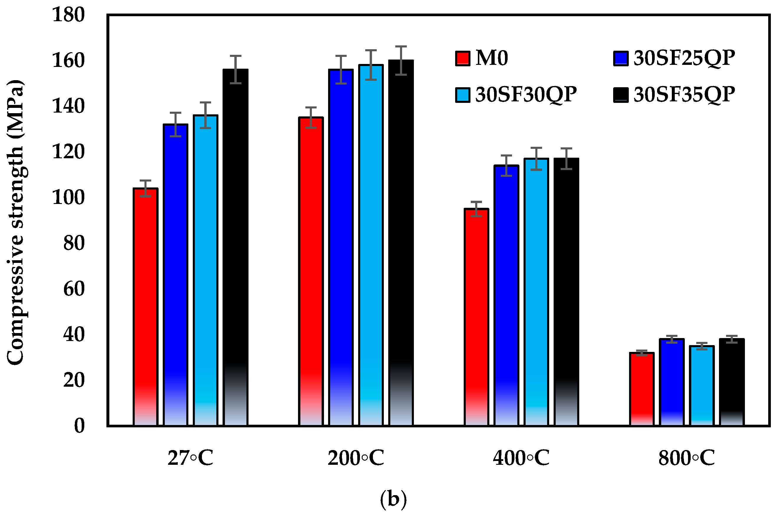
Under ambient conditions (27 °C), G-UHPC mixtures incorporating 30% SF consistently outperformed those with 15% SF and the control mix (M0). Notably, the 30SF35QP mix achieved a peak compressive strength of 156 MPa, compared to 146.83 MPa for 15SF35QP and 104 MPa for M0, underscoring the synergistic effect of higher SF content and QP addition in enhancing matrix densification and strength development.
(c)
G-UHPC with 30% SF and 35% QP attained an impressive compressive strength of 156 MPa at ambient temperature, demonstrating the potential of this formulation for high-strength applications.
(d)
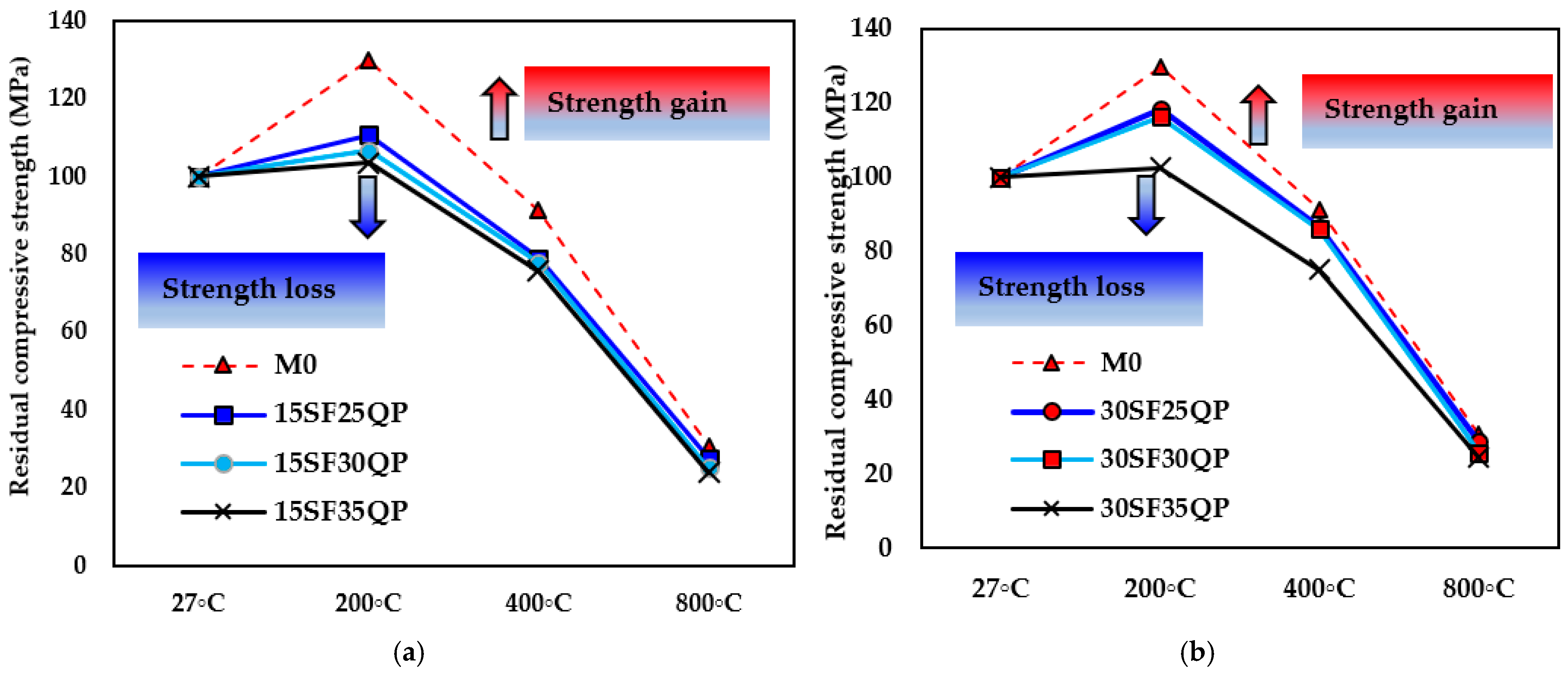
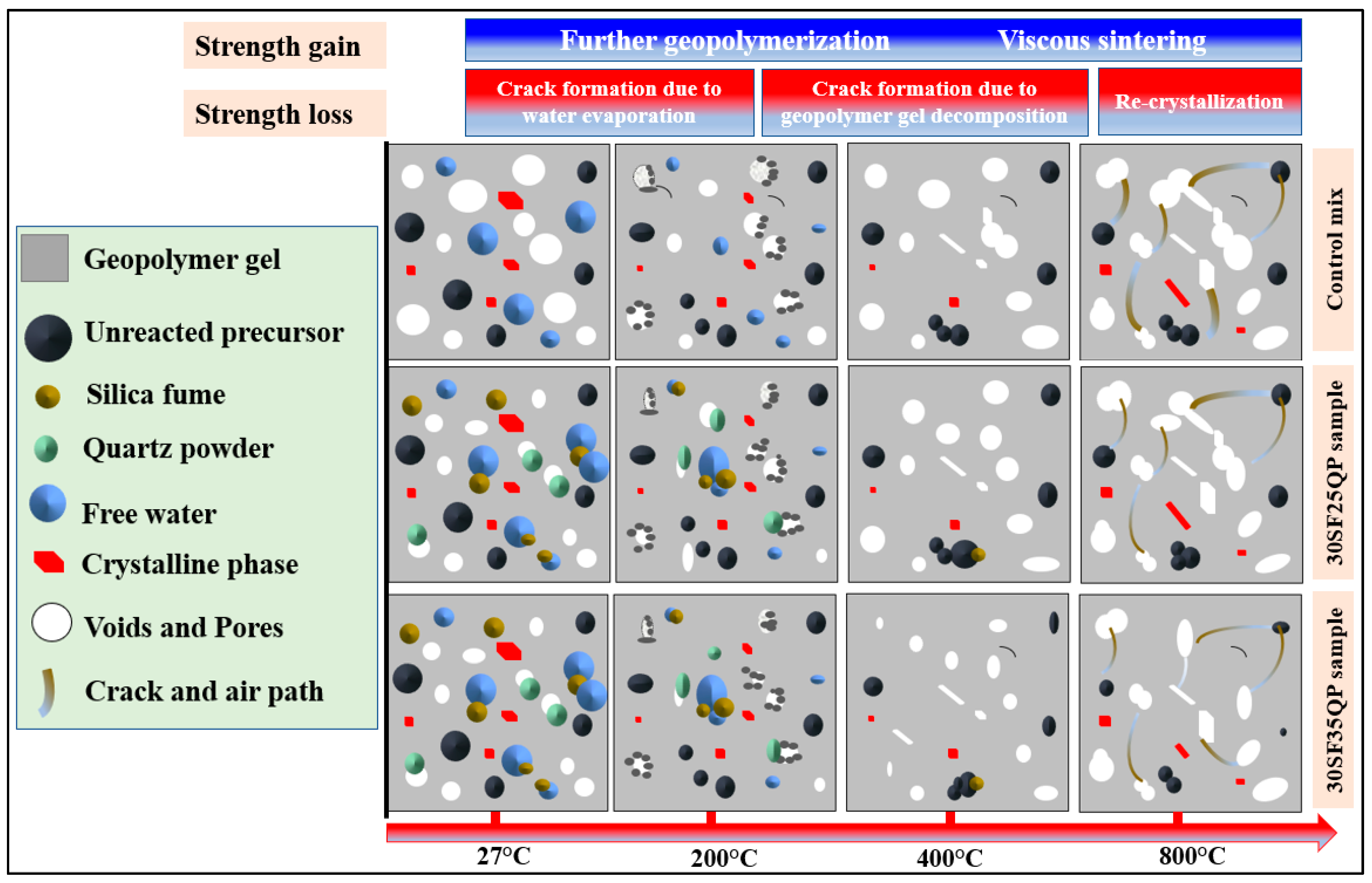
At 200 °C, all mixes exhibited enhanced compressive strength due to accelerated geopolymerization, with the control mix gaining 29.8% (135 MPa). This improvement is attributed to the formation of denser C-A-S-H and N-A-S-H gels during thermal treatment.
(e)
At 800 °C, the 30SF35QP mix retained 38 MPa of its initial strength, corresponding to 24.4% of its ambient compressive strength—a reduction of 75.6%. Similarly, the 30SF25QP mix also retained 38 MPa, equating to 28% strength retention. Both outperformed the control mix, which retained only 30.8% (32 MPa). These results highlight the superior thermal stability of G-UHPC incorporating 30% SF and 35% QP, demonstrating enhanced resistance to thermal degradation compared to lower SF content mixtures.
(f)
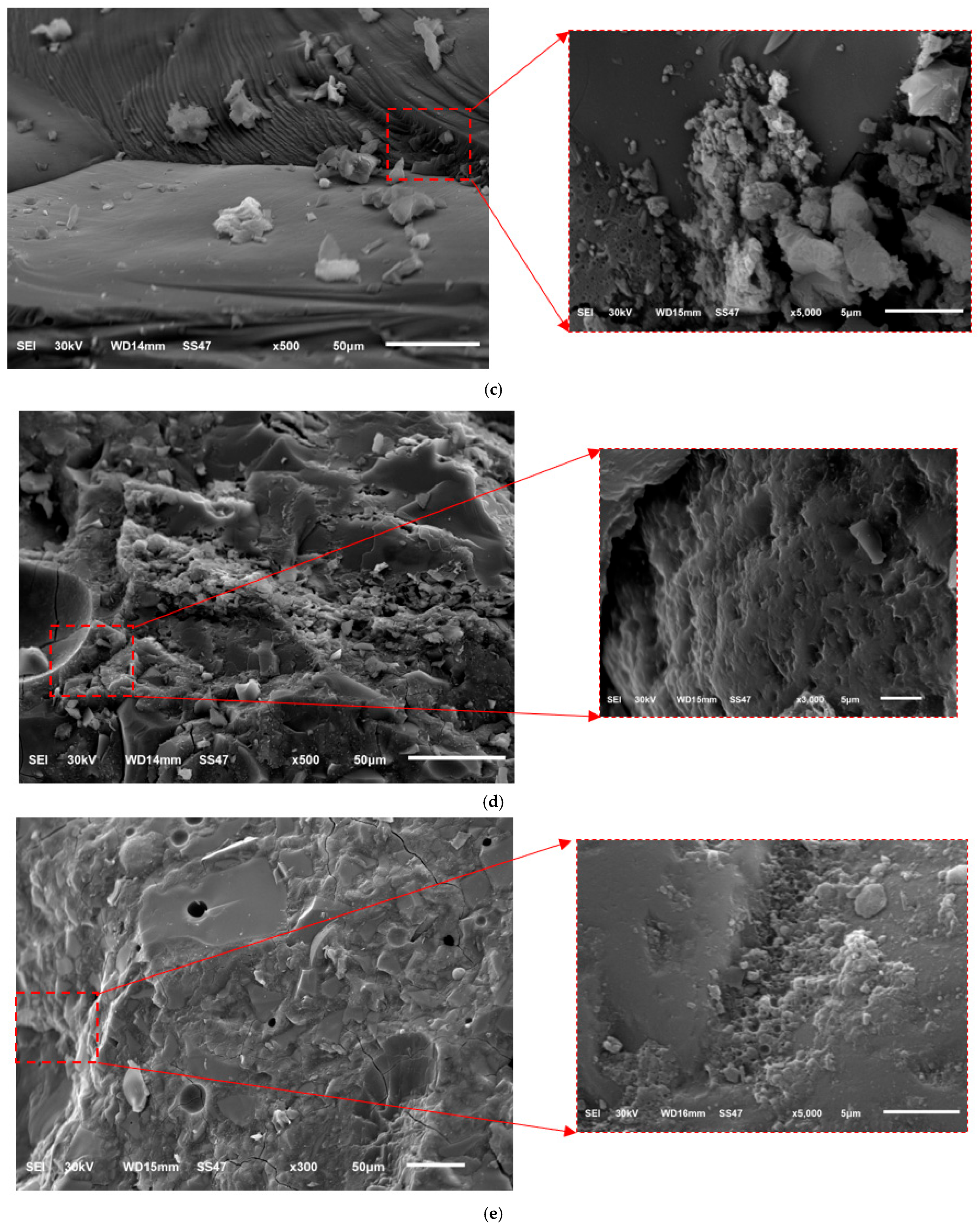
Microstructural analysis via SEM revealed that the strength reductions at 400 °C and 800 °C were due to increased porosity and crack formation, driven by the decomposition of C-A-S-H and N-A-S-H gels, water vapor release, and volumetric expansion. However, 30SF35QP exhibited greater compactness and fewer voids, correlating with its superior residual strength.
In general, the 30SF35QP mix offers a robust solution for G-UHPC applications requiring high mechanical strength and thermal resistance, even without fiber reinforcement. These findings underscore the potential of G-UHPC for use in extreme environments, such as fire-exposed structures, while providing a foundation for further research into fiber-reinforced formulations.

Author Contributions

Conceptualization, R.A.E. and A.M.T.; methodology, W.E.E.; software, M.A.; validation, M.A., W.E.E. and A.M.T.; formal analysis, R.A.E.; investigation, R.A.E.; resources, M.A.; data curation, A.M.T.; writing—original draft preparation, R.A.E.; writing—review and editing, M.A.; visualization, A.M.T.; supervision, A.M.T.; project administration, W.E.E.; funding acquisition, A.M.T. All authors have read and agreed to the published version of the manuscript.

Funding

This research received no external funding.

Data Availability Statement

The original contributions presented in this study are included in the article. Further inquiries can be directed to the corresponding authors.

Conflicts of Interest

The authors declare no conflict of interest.

References

  1. Shoukry, H.; Perumal, P.; Abadel, A.; Alghamdi, H.; Alamri, M.; Abdel-Gawwad, H.A. Performance of limestone-calcined clay cement mortar incorporating high volume ferrochrome waste slag aggregate. Constr. Build. Mater. 2022, 350, 128928. [Google Scholar] [CrossRef]
  2. Dong, Y. Performance assessment and design of ultra-high performance concrete (UHPC) structures incorporating life-cycle cost and environmental impacts. Constr. Build. Mater. 2018, 167, 414–425. [Google Scholar] [CrossRef]
  3. Stengel, T.; Schießl, P. 22—Life cycle assessment (LCA) of ultra high performance concrete (UHPC) structures. In Eco-Efficient Construction and Building Materials; Pacheco-Torgal, F., Cabeza, L.F., Labrincha, J., de Magalhães, A., Eds.; Woodhead Publishing: Sawston, UK, 2014; pp. 528–564. [Google Scholar] [CrossRef]
  4. Papadakis, V.G.; Fardis, M.N.; Vayenas, C.G. Effect of composition, environmental factors and cement-lime mortar coating on concrete carbonation. Mater. Struct. 1992, 25, 293–304. [Google Scholar] [CrossRef]
  5. Elfadaly, E.; Othman, A.M.; Aly, M.H.; Elgarhy, W.A.; Abdellatief, M. Assessing performance and environmental benefits of high-performance geopolymer mortar incorporating pumice and rice straw ash. Sustain. Chem. Pharm. 2025, 44, 101918. [Google Scholar] [CrossRef]
  6. Pasupathy, K.; Berndt, M.; Sanjayan, J.; Rajeev, P.; Cheema, D.S. Durability of low calcium fly ash based geopolymer concrete culvert in a saline environment. Cem. Concr. Res. 2017, 100, 297–310. [Google Scholar] [CrossRef]
  7. Althoey, F.; Zaid, O.; Martínez-García, R.; de Prado-Gil, J.; Ahmed, M.; Yosri, A.M. Ultra-high-performance fiber-reinforced sustainable concrete modified with silica fume and wheat straw ash. J. Mater. Res. Technol. 2023, 24, 6118–6139. [Google Scholar] [CrossRef]
  8. Abdellatief, M.; AL-Tam, S.M.; Elemam, W.E.; Alanazi, H.; Elgendy, G.M.; Tahwia, A.M. Development of ultra-high-performance concrete with low environmental impact integrated with metakaolin and industrial wastes. Case Stud. Constr. Mater. 2023, 18, e01724. [Google Scholar] [CrossRef]
  9. Abdellatief, M.; Murali, G.; Dixit, S. Leveraging machine learning to evaluate the effect of raw materials on the compressive strength of ultra-high-performance concrete. Results Eng. 2025, 25, 104542. [Google Scholar] [CrossRef]
  10. Plevny, Z. Applications of Ultra-High Performance Concrete; IdeaExchange@UAkron: Akron, OH, USA, 2020. [Google Scholar]
  11. Abdal, S.; Mansour, W.; Agwa, I.; Nasr, M.; Abadel, A.; Özkılıç, Y.O.; Akeed, M.H. Application of Ultra-High-Performance Concrete in Bridge Engineering: Current Status, Limitations, Challenges, and Future Prospects. Buildings 2023, 13, 185. [Google Scholar] [CrossRef]
  12. Anunike, G.S.; Tarabin, M.; Hisseine, O.A. Ultra-high-performance concrete for nuclear applications: A review of raw materials and mix design approaches. Constr. Build. Mater. 2024, 438, 136938. [Google Scholar] [CrossRef]
  13. Shi, C.; Wu, Z.; Xiao, J.; Wang, D.; Huang, Z.; Fang, Z. A review on ultra high performance concrete: Part I. Raw materials and mixture design, Constr. Build. Mater. 2015, 101, 741–751. [Google Scholar] [CrossRef]
  14. Amran, Y.H.M.; Alyousef, R.; Alabduljabbar, H.; El-Zeadani, M. Clean production and properties of geopolymer concrete; A review. J. Clean. Prod. 2020, 251, 119679. [Google Scholar] [CrossRef]
  15. Wu, Z.; Shi, C.; He, W. Comparative study on flexural properties of ultra-high performance concrete with supplementary cementitious materials under different curing regimes. Constr. Build. Mater. 2017, 136, 307–313. [Google Scholar] [CrossRef]
  16. Kioupis, D.; Zisimopoulou, A.; Tsivilis, S.; Kakali, G. Development of porous geopolymers foamed by aluminum and zinc powders. Ceram. Int. 2021, 47, 26280–26292. [Google Scholar] [CrossRef]
  17. Li, B.; Jiang, G.; Hu, J.; Li, Y.; Wu, F.; Qin, Z.; Wang, S. Specimen size effect on compressive and splitting tensile strengths of sustainable geopolymeric recycled aggregate concrete: Experimental and theoretical analysis. J. Clean. Prod. 2024, 434, 140154. [Google Scholar] [CrossRef]
  18. Khale, D.; Chaudhary, R. Mechanism of geopolymerization and factors influencing its development: A review. J. Mater. Sci. 2007, 42, 729–746. [Google Scholar] [CrossRef]
  19. Tahwia, A.M.; Abdellatief, M.; Salah, A.; Youssf, O. Valorization of recycled concrete powder, clay brick powder, and volcanic pumice powder in sustainable geopolymer concrete. Sci. Rep. 2025, 15, 11049. [Google Scholar] [CrossRef] [PubMed]
  20. Beltrame, N.A.M.; Dias, R.L.; Witzke, F.B.; Medeiros-Junior, R.A. Effect of carbonation curing on the physical, mechanical, and microstructural properties of metakaolin-based geopolymer concrete. Constr. Build. Mater. 2023, 406, 133403. [Google Scholar] [CrossRef]
  21. Abdellatief, M.; Elrahman, M.A.; Abadel, A.A.; Wasim, M.; Tahwia, A. Ultra-high performance concrete versus ultra-high performance geopolymer concrete: Mechanical performance, microstructure, and ecological assessment. J. Build. Eng. 2023, 79, 107835. [Google Scholar] [CrossRef]
  22. Tahwia, A.M.; Ellatief, M.A.; Bassioni, G.; Heniegal, A.M.; Elrahman, M.A. Influence of high temperature exposure on compressive strength and microstructure of ultra-high performance geopolymer concrete with waste glass and ceramic. J. Mater. Res. Technol. 2023, 23, 5681–5697. [Google Scholar] [CrossRef]
  23. Xie, Y.; Wang, C.; Guo, Y.; Cui, H.; Xue, J. Improved mechanical and thermal properties of sustainable ultra-high performance geopolymer concrete with cellulose nanofibers. J. Build. Eng. 2025, 102, 112068. [Google Scholar] [CrossRef]
  24. Ellatief, M.A.; Abadel, A.A.; Federowicz, K.; Elrahman, M.A. Mechanical properties, high temperature resistance and microstructure of eco-friendly ultra-high performance geopolymer concrete: Role of ceramic waste addition. Constr. Build. Mater. 2023, 401, 132677. [Google Scholar] [CrossRef]
  25. Althoey, F.; Zaid, O.; Alsulamy, S.; Martínez-García, R.; de Prado-Gil, J.; Arbili, M.M. Experimental study on the properties of ultra-high-strength geopolymer concrete with polypropylene fibers and nano-silica. PLoS ONE 2023, 18, e0282435. [Google Scholar] [CrossRef] [PubMed]
  26. Xiong, X.; Wu, M.; Shen, W.; Li, J.; Zhao, D.; Li, P.; Wu, J. Performance and microstructure of ultra-high-performance concrete (UHPC) with silica fume replaced by inert mineral powders. Constr. Build. Mater. 2022, 327, 126996. [Google Scholar] [CrossRef]
  27. Abdellatief, M.; Elrahman, M.A.; Elgendy, G.; Bassioni, G.; Tahwia, A.M. Response surface methodology-based modelling and optimization of sustainable UHPC containing ultrafine fly ash and metakaolin. Constr. Build. Mater. 2023, 388, 131696. [Google Scholar] [CrossRef]
  28. Tavares, L.R.C.; Junior, J.F.T.; Costa, L.M.; da Silva Bezerra, A.C.; Cetlin, P.R.; Aguilar, M.T.P. Influence of quartz powder and silica fume on the performance of Portland cement. Sci. Rep. 2020, 10, 21461. [Google Scholar] [CrossRef] [PubMed]
  29. Lin, R.-S.; Wang, X.-Y.; Zhang, G.-Y. Effects of Quartz Powder on the Microstructure and Key Properties of Cement Paste. Sustainability 2018, 10, 3369. [Google Scholar] [CrossRef]
  30. Cai, R.; Wu, T.; Fu, C.; Ye, H. Thermal degradation of potassium-activated ternary slag-fly ash-silica fume binders. Constr. Build. Mater. 2022, 320, 126304. [Google Scholar] [CrossRef]
  31. Mashri, M.O.M.; Johari, M.A.M.; Ahmad, Z.A.; Mijarsh, M.J.A. Enhancing the properties of UPOFA-based geopolymer mortar via the incorporation of eggshell ash and silica fume. J. Build. Eng. 2023, 65, 105677. [Google Scholar] [CrossRef]
  32. Wetzel, A.; Middendorf, B. Influence of silica fume on properties of fresh and hardened ultra-high performance concrete based on alkali-activated slag. Cem. Concr. Compos. 2019, 100, 53–59. [Google Scholar] [CrossRef]
  33. Althoey, F.; Zaid, O.; Alsulamy, S.; Martínez-García, R.; de Prado Gil, J.; Arbili, M.M. Determining engineering properties of ultra-high-performance fiber-reinforced geopolymer concrete modified with different waste materials. PLoS ONE 2023, 18, e0285692. [Google Scholar] [CrossRef] [PubMed]
  34. ASTM C618-22; Standard Specification for Coal Fly Ash and Raw or Calcined Natural Pozzolan for Use in Concrete. ASTM International: West Conshohocken, PA, USA, 1995; Volume 14. pp. 4–5. [CrossRef]
  35. E 778-87; Standard Test Methods for Nitrogen in the Analysis Sample of Refuse-Derived Fuel. iTeh Standards: San Francisco, CA, USA, 2004; pp. 3–5.
  36. ASTM C33/C33M; Standard Specification for Concrete Aggregates, ASTM C33-86. ASTM Standards: West Conshohocken, PA, USA, 2008; Volume 11. p. 11.
  37. ASTM C109/109M; Standard test Method for Compressive Strength of Hydraulic Cement Mortars (Using 2-in. or cube specimens). ASTM Standards: West Conshohocken, PA, USA, 2016; pp. 1–10.
  38. ASTM C78/C78M-22; Standard Test Method for Flexural Strength of Concrete (Using Simple Beam with Third-Point Loading) 1, Hand The C78-02. ASTM Standards: West Conshohocken, PA, USA, 2010; pp. 1–4.
  39. Liu, Y.; Shi, C.; Zhang, Z.; Li, N.; Shi, D. Mechanical and fracture properties of ultra-high performance geopolymer concrete: Effects of steel fiber and silica fume. Cem. Concr. Compos. 2020, 112, 103665. [Google Scholar] [CrossRef]
  40. Murali, G.; Nassar, A.K.; Swaminathan, M.; Kathirvel, P.; Wong, L.S. Effect of silica fume and glass powder for enhanced impact resistance in GGBFS-based ultra high-performance geopolymer fibrous concrete: An experimental and statistical analysis. Def. Technol. 2024, 41, 59–81. [Google Scholar] [CrossRef]
  41. Wu, Z.; Shi, C.; Khayat, K.H. Influence of silica fume content on microstructure development and bond to steel fiber in ultra-high strength cement-based materials (UHSC). Cem. Concr. Compos. 2016, 71, 97–109. [Google Scholar] [CrossRef]
  42. Karthikeyan, B.; Dhinakaran, G. Influence of ultrafine TiO2 and silica fume on performance of unreinforced and fiber reinforced concrete. Constr. Build. Mater. 2018, 161, 570–576. [Google Scholar] [CrossRef]
  43. Tayeh, B.A.; Akeed, M.H.; Qaidi, S.; Bakar, B.H.A. Influence of microsilica and polypropylene fibers on the fresh and mechanical properties of ultra-high performance geopolymer concrete (UHP-GPC). Case Stud. Constr. Mater. 2022, 17, e01367. [Google Scholar] [CrossRef]
  44. Behnood, A.; Ziari, H. Effects of silica fume addition and water to cement ratio on the properties of high-strength concrete after exposure to high temperatures. Cem. Concr. Compos. 2008, 30, 106–112. [Google Scholar] [CrossRef]
  45. Li, L.G.; Kwan, A.K.H. Concrete mix design based on water film thickness and paste film thickness. Cem. Concr. Compos. 2013, 39, 33–42. [Google Scholar] [CrossRef]
  46. Aisheh, Y.I.A.; Atrushi, D.S.; Akeed, M.H.; Qaidi, S.; Tayeh, B.A. Influence of steel fibers and microsilica on the mechanical properties of ultra-high-performance geopolymer concrete (UHP-GPC). Case Stud. Constr. Mater. 2022, 17, e01245. [Google Scholar] [CrossRef]
  47. Xi, Y.; Siemer, D.D.; Scheetz, B.E. Strength development, hydration reaction and pore structure of autoclaved slag cement with added silica fume. Cem. Concr. Res. 1997, 27, 75–82. [Google Scholar] [CrossRef]
  48. de Azevedo, A.R.G.; Cruz, A.S.A.; Marvila, M.T.; de Oliveira, L.B.; Monteiro, S.N.; Vieira, C.M.F.; Fediuk, R.; Timokhin, R.; Vatin, N.; Daironas, M. Natural fibers as an alternative to synthetic fibers in reinforcement of geopolymer matrices: A comparative review. Polymers 2021, 13, 2493. [Google Scholar] [CrossRef] [PubMed]
  49. Jiao, Y.; Zhang, Y.; Guo, M.; Zhang, L.; Ning, H.; Liu, S. Mechanical and fracture properties of ultra-high performance concrete (UHPC) containing waste glass sand as partial replacement material. J. Clean. Prod. 2020, 277, 123501. [Google Scholar] [CrossRef]
  50. Kathirvel, P.; Sreekumaran, S. Sustainable development of ultra high performance concrete using geopolymer technology. J. Build. Eng. 2021, 39, 102267. [Google Scholar] [CrossRef]
  51. Zhang, H.; Li, L.; Yuan, C.; Wang, Q.; Sarker, P.K.; Shi, X. Deterioration of ambient-cured and heat-cured fly ash geopolymer concrete by high temperature exposure and prediction of its residual compressive strength. Constr. Build. Mater. 2020, 262, 120924. [Google Scholar] [CrossRef]
  52. Niu, M.; Zhang, P.; Guo, J.; Wang, J. Effect of Municipal Solid Waste Incineration Fly Ash on the Mechanical Properties and Microstructure of Geopolymer Concrete. Gels 2022, 8, 341. [Google Scholar] [CrossRef] [PubMed]
  53. Huang, L.; Liu, J.C.; Cai, R.; Ye, H. Mechanical degradation of ultra-high strength alkali-activated concrete subjected to repeated loading and elevated temperatures. Cem. Concr. Compos. 2021, 121, 104083. [Google Scholar] [CrossRef]
  54. Ouda, A.S.; Gharieb, M. Behavior of alkali-activated pozzocrete-fly ash paste modified with ceramic tile waste against elevated temperatures and seawater attacks. Constr. Build. Mater. 2021, 285, 122866. [Google Scholar] [CrossRef]
  55. Cai, R.; Ye, H. Clinkerless ultra-high strength concrete based on alkali-activated slag at high temperatures. Cem. Concr. Res. 2021, 145, 106465. [Google Scholar] [CrossRef]
  56. Yu, M.; Wang, T.; Chi, Y.; Li, D.; Li, L.Y.; Shi, F. Residual mechanical properties of GGBS-FA-SF blended geopolymer concrete after exposed to elevated temperatures. Constr. Build. Mater. 2024, 411, 134378. [Google Scholar] [CrossRef]
  57. Swathi, B.; Vidjeapriya, R. Influence of precursor materials and molar ratios on normal, high, and ultra-high performance geopolymer concrete—A state of art review. Constr. Build Mater. 2023, 392, 132006. [Google Scholar] [CrossRef]
  58. Abdellatief, M.; Adel, B.; Alanazi, H.; Tawfik, T.A. Multiscale optimization analysis of high strength alkali-activated concrete containing waste medical glass under exposure to carbonation and elevated temperatures. Dev. Built Environ. 2024, 19, 100492. [Google Scholar] [CrossRef]
  59. Wan, X.; Shen, C.; Wang, P.; Zhao, T.; Lu, Y. A study on fracture toughness of ultra-high toughness geopolymer composites based on Double-K Criterion. Constr. Build. Mater. 2020, 251, 118851. [Google Scholar] [CrossRef]
  60. Gholampour, A.; Ho, V.D.; Ozbakkaloglu, T. Ambient-cured geopolymer mortars prepared with waste-based sands: Mechanical and durability-related properties and microstructure. Compos. B Eng. 2019, 160, 519–534. [Google Scholar] [CrossRef]
  61. Albidah, A.; Alqarni, A.S.; Abbas, H.; Almusallam, T.; Al-Salloum, Y. Behavior of Metakaolin-Based geopolymer concrete at ambient and elevated temperatures. Constr. Build. Mater. 2022, 317, 125910. [Google Scholar] [CrossRef]
  62. Tahwia, A.M.; Ellatief, M.A.; Heneigel, A.M.; Elrahman, M.A. Characteristics of eco-friendly ultra-high-performance geopolymer concrete incorporating waste materials. Ceram. Int. 2022, 48, 19662–19674. [Google Scholar] [CrossRef]
  63. Huang, J.; Li, J.; Shao, R.; Wu, C. Effect of high temperature and cooling method on compression and fracture properties of geopolymer-based ultra-high performance concrete. J. Build. Eng. 2025, 105, 112433. [Google Scholar] [CrossRef]
  64. Luo, Y.; Li, S.H.; Klima, K.M.; Brouwers, H.J.H.; Yu, Q. Degradation mechanism of hybrid fly ash/slag based geopolymers exposed to elevated temperatures. Cem. Concr. Res. 2022, 151, 106649. [Google Scholar] [CrossRef]
Figure 1. Raw materials employed in this investigation. (a) GGBFS, (b) SF, (c) QP and (d) Nature sand.
Infrastructures 10 00192 g001
Figure 2. Role of SF in enhancing microstructure of G-UHPC.
Infrastructures 10 00192 g002
Figure 3. PSD of GGBFS and SF. (a) GGBFS; (b) SF.
Infrastructures 10 00192 g003
Figure 4. Mechanical properties tests. (a) Compressive strength and (b) flexural strength.
Infrastructures 10 00192 g004aInfrastructures 10 00192 g004b
Figure 5. (a,b) denote the specimens heated in the furnace, and (c) shows the schematic diagram of the heating curve for different target temperatures.
Infrastructures 10 00192 g005aInfrastructures 10 00192 g005b
Figure 6. Compressive strength results at 15% SF with different ratios of QP.
Infrastructures 10 00192 g006
Figure 7. Compressive strength results at 30% SF with different ratios of QP.
Infrastructures 10 00192 g007
Figure 8. The flexural strength of G-UHPC at optimized mixtures.
Infrastructures 10 00192 g008
Figure 9. Visual appearance of specimens after exposure to high temperature. (a) M0; (b) 15SF35QP; (c) 30SF35QP.
Infrastructures 10 00192 g009
Figure 10. The variation in compressive strength after exposure to elevated temperatures at (a) 15%SF and (b) 30%SF.
Infrastructures 10 00192 g010aInfrastructures 10 00192 g010b
Figure 11. Residual compressive strengths of G-UHPC at elevated temperatures: (a) 15%SF and (b) 30%SF.
Infrastructures 10 00192 g011
Figure 12. SEM for different G-UHPC mixes before exposure to elevated temperatures. (a) M0. (b) 15SF25QP specimen. (c) 15SF35QP specimen. (d) 30SF25QP specimen. (e) 30SF35QP specimen.
Infrastructures 10 00192 g012aInfrastructures 10 00192 g012b
Figure 13. EDS comparison of G-UHPC before exposure to elevated temperatures. (a) M0. (b) 15SF25QP specimen. (c) 15SF35QP specimen. (d) 30SF25QP specimen. (e) 30SF35QP specimen.
Infrastructures 10 00192 g013aInfrastructures 10 00192 g013b
Figure 14. SEM for different G-UHPC mixes after exposure to elevated temperatures at 800 °C. (a) M0. (b) 15SF25QP specimen. (c) 15SF35QP specimen. (d) 30SF25QP specimen. (e) 30SF35QP specimen.
Infrastructures 10 00192 g014aInfrastructures 10 00192 g014b
Figure 15. XRD for different G-UHPC mixes before and after exposure to elevated temperatures at 800 °C.
Infrastructures 10 00192 g015
Figure 16. Schematic representation of the degradation mechanism of G-UHPC mixtures at elevated temperatures.
Infrastructures 10 00192 g016
Table 1. Chemicals of GGBFS, SF, and QP.
Oxides (%)CaoSiO2Al2O3MgOFe2O3SO3
GGBFS38.8032.6015.606.021.361.83
SF1.4592.180.680.760.570.50
QP0.0499.650.0850.0030.01-
Table 2. Proportioning of aggregates (% by weight).
ClassQPType IType II
A255025
B304525
C354025
Table 3. Characteristics for the proportion of mix (kg/m3).
Mix IDGGBFSSFAggregatesNaOHSSSP
QPSand
M098000110011419119
15SF25QP83511627582511419119
15SF30QP83511633077011419119
15SF35QP83511638571511419119
30SF25QP68623327582511419119
30SF30QP68623333077011419119
30SF35QP68623338571511419119
Table 4. Compressive strength results of G-UHPC.
Mix ID7 Days28 Days56 Days
M095.0100.0104.0
15SF25QP109.06120.5126.57
15SF30QP104.67127.46139.03
15SF35QP112.67132.8146.83
30SF25QP103.0110.0132.0
30SF30QP104.0112.0136.0
30SF35QP108.0143.0156.0
Table 5. Summary of G-UHPC performance at ambient and elevated temperatures.
Temp.Mass LossResidual Compressive StrengthObservable Material BehaviorRef.
AmbientNegligible104–156 MPaDense microstructure with minimal unreacted particles; intact matrix with C-A-S-H and N-A-S-H gels.[24,25,33]
200 °CMinimal (1–3%)Increased by 3.5–29.8%Slight densification due to enhanced geopolymerization; no visible cracking; matrix remains intact.[22,24,30]
400 °CModerate (5–10%)75.0–91.3% retentionOnset of microstructural damage; minor voids and cracks form due to bound water evaporation; material remains serviceable.[24,25,33]
800 °CSignificant (15–20%)23.8–30.8% retentionSevere degradation with extensive porosity and cracking; breakdown of C-A-S-H and N-A-S-H gels; compromised structural integrity.[22,24,30]
Disclaimer/Publisher’s Note: The statements, opinions and data contained in all publications are solely those of the individual author(s) and contributor(s) and not of MDPI and/or the editor(s). MDPI and/or the editor(s) disclaim responsibility for any injury to people or property resulting from any ideas, methods, instructions or products referred to in the content.

