Article

Comparison of Pulse-Echo Tomography and Through-Transmission Ultrasonic Test for UPV Characterization of Building Materials

1
Institute of Heritage Science (ISPC), National Research Council (CNR), Via per Monteroni, 73100 Lecce, Italy
2
Department of Engineering for Innovation, University of Salento, Via per Monteroni, 73100 Lecce, Italy
3
Institute of Methodologies for Environmental Analysis (IMAA), National Research Council (CNR), C.da S. Loja (Zona Industriale), 85050 Tito Scalo, Italy
*
Author to whom correspondence should be addressed.
Infrastructures 2025, 10(7), 162; https://doi.org/10.3390/infrastructures10070162
Submission received: 14 May 2025 / Revised: 18 June 2025 / Accepted: 25 June 2025 / Published: 27 June 2025
(This article belongs to the Section Infrastructures Materials and Constructions)

Abstract

Ultrasonic pulse velocity (UPV) is a widely used technique for diagnosis and structural safety assessment of existing buildings. The main difficulties in UPV tests on-site are due to one-sided accessibility of materials and degraded/irregular surfaces. Pulse-echo ultrasonic tomography (PE-UT) can overcome the problem. Though it has been widely applied for detecting inhomogeneities within concrete, few works use the instrument to assess UPV. The present paper aims to fill the gap by comparing PE-UT results with those of through-transmission ultrasonic tests (TT-UT) commonly used for UPV characterization. TT-UT measurements were performed with cylindrical and exponential transducers. The latter are used on irregular surfaces or when coupling gel is forbidden. Few data are in the literature comparing exponential and cylindrical transducers’ results. This is a further element of novelty of the paper. PE-UT and TT-UT results were compared considering the effect of material compositeness, water, transmission mode, and transducer type. It was found that PE-UT allows for reliable and rapid one-sided measurements on concrete and stone in different conditions. The differences between PE-UT and TT-UT results were between 1 and 3%. Exponential transducers gave reliable results on fine-grained stone in direct transmission, with differences lower than 4% with cylindrical transducer results.

1. Introduction

In structural safety assessment of existing buildings, ultrasonic measurements are commonly used diagnostic tools to evaluate the quality and properties of the materials employed [1]. Indeed, ultrasonic velocities can be correlated to several material properties like strength, elastic constants, density, and porosity [2,3]. The method is also used to detect the presence of cracks and inhomogeneous or degraded regions within the materials [4,5,6]. Practitioners and engineers often use ultrasonic pulse velocity (UPV) to assess concrete strength within existing buildings. Knowing the strength of building materials is a key challenge in many situations, such as quality control during building construction, design of repair and/or strengthening measurements, and evaluation of residual mechanical properties after the effect of aging or damage on existing structures. Thus, ultrasonic techniques may be a solution to estimate concrete strength, reducing the number of cores extracted from the buildings and the invasiveness of diagnosis [3]. In this regard, the accuracy and reliability of the UPV measurement are essential to estimate material strength for structural purposes.
One of the major difficulties in UPV measurements onsite is the one-sided accessibility of the structural members. When through-transmission ultrasonic tests (TT-UT) are performed, the direct method is the most desirable arrangement of transducers because the maximum energy of the pulse is transmitted and received. On the other hand, it is not always possible to access both sides of the element. In these cases, indirect transmission measures should be performed [7]. When this measurement method is used, the pulse propagates in the superficial layers of the material that are sometimes of a composition slightly different from the material in the volume. Thus, the velocities measured by the indirect (surface) transmission method are typically lower than those measured with direct transmission [8]. It was found that the extent of the differences between direct and indirect UPV results varied depending on the material’s properties and state of conservation [9,10,11].
Another one-sided ultrasonic measurement technique that has spread in the last two decades is pulse-echo ultrasound tomography (PE-UT). The pulse-echo method introduces a stress pulse from a transmitter into an object at an accessible surface. The pulse propagates into the test object and is reflected by flaws or interfaces. The surface response caused by the arrival of reflected waves, or echoes, is monitored by receivers. Tomography gives visualization, either by cross-section or 3D images, of the interior structure of the object to find anomalies and determine the material’s physical properties [12]. PE-UT employs dry-point contact transducers (DPCT), which allow good coupling with irregular or degraded surfaces without coupling gel, and transverse S-waves instead of longitudinal P-waves because it has been proved that they give more reliable results for degraded concrete and in the presence of defects [13]. In the literature, there are several studies in which tomographic images are used to detect the presence of defects in structural members [14,15,16]. In these cases, a reference value of UPV is assumed. On the contrary, few studies use PE-UT images to determine UPV in building materials [17,18,19]. Thus, the appropriateness and reliability of this technique to assess UPV are still under investigation due to the lack of a sufficient number of published experimental studies.
Based on the above considerations, the present paper aims to investigate the reliability of PE-UT measurements by comparing their results with those of TT-UT, commonly used for UPV assessment. The influence of different variables has been considered: The compositeness of the material, the presence of water, the TT-UT measuring mode (direct, indirect), and the type of velocity determination (superficial, calibration) from PE-UT images.
The influence of material compositeness can be examined in concrete by varying the water-cement ratio, the maximum aggregate size, the type of cement, and the air content in the mix. These factors affect the grain and pore dimensions of the material, and thus its compositeness. In this research, we chose to investigate this aspect by testing two different materials: concrete and stone (Lecce stone). This approach allows us to extend the research results to masonry structures. Lecce stone, a soft calcarenite widely used in the baroque architecture of Salento in southern Italy, has smaller grain and pore dimensions than concrete, along with lower stiffness and mechanical resistance.
Concrete and Lecce stones were examined in ambient and saturated conditions to assess the impact of water on PE-UT and TT-UT results. Indeed, water is a parameter frequently encountered on-site, and its presence significantly influences UPV measurements [11].
TT-UT measurements were performed with two kinds of transducers, cylindrical and exponential. Exponential transducers have the same constructive characteristics as cylindrical ones but with an added tip with an exponential shape [20,21]. The result is a contact point of dimensions typically lower than 1 mm. Exponential transducers have the advantage of not requiring the use of coupling agents. Due to the small tip, they adapt to all surfaces independently of their roughness. They are widely used on-site with degraded, irregular, or rounded surfaces, or when coupling gel is forbidden, as in the case of architectural heritage. On the other hand, the exponential tip reduces the signal power and causes higher registered times of wave arrival [20,21]. Increasing the gain setting can improve the readability of the signal and its arrival time determination. In the literature, there are few works on the comparison of exponential transducer results with those of cylindrical ones [11,22]. In this contest, performing the tests with both transducers and comparing their results with each other is a further element of novelty of the paper.
TT-UT measurements with cylindrical and exponential transducers were performed in direct and indirect transmission modes, and the results of the tests were analyzed and discussed in the first part of the paper.
The PE-UT test was performed on the same specimens investigated by TT-UT. The effect of the material tested, concrete or stone, the influence of water, and the mode in which velocity was determined from tomographic images were discussed. The S-wave velocity results of PE-UT were then converted into P-wave velocity to compare the results with those of TT-UT in direct and indirect transmission modes.
Based on experimental results, the paper aims to improve knowledge on the PE-UT technique for UPV characterization of building materials, allowing practitioners and engineers to use it with awareness of its advantages and limitations. Additionally, more information will be obtained from the research on exponential transducers on concrete and stone members.

2. Materials and Methods

Concrete and Lecce stone specimens were investigated in ambient and saturated conditions. TT-UT tests, direct (Figure 1b) and indirect (Figure 1c) modes, were first performed, followed by PE-UT tests (Figure 1a). The following paragraphs include the details on the material investigated and UPV measuring techniques.

2.1. Materials

Concrete and Lecce Stone specimens were used in this work.
The concrete formulation was 293 kg/m3 of 32.5 R cement type [23], 753 kg/m3 of sand (0–4 mm), 350 kg/m3 of 8–16 mm gravel, 332 kg/m3 of 12–20 mm gravel, and 5 kg/m3 of superplasticizer based on modified polycarboxylates. The water-cement ratio was fixed at 0.52. The compressive strength of the concrete was 35.80 ± 1.81 MPa, as determined on cubic specimens according to [24].
Lecce stone is classified as a fine-grained biocalcarenite. It consists of fine microfossil fragments (mainly planktonic foraminifera), fossil debris, micritic groundmass, and dispersed clay minerals. The porosity is mostly intergranular, sometimes intragranular with microfossil cavities [2]. The maximum grain dimension of the stone is 2 mm, and its porosity, measured by Mercury Intrusion Porosimetry, ranges between 30% and 43% [25]. The compressive strength of cubic specimens varies between 15 and 30 MPa [2].

2.2. Through-Transmission Ultrasonic Tests

UPV measurements in direct and indirect transmission modes were performed according to the UNI EN 12504-4:2005 standard [26]. The Pundit PL 200 (Proceq—Screening Eagle, Zurich Switzerland) instrument was used to acquire ultrasonic wave signals in direct and indirect transmission modes. The instrument has a bandwidth between 20 and 500 kHz, a measuring resolution of 0.1 μs, and a range of measuring time between 0.1 and 7930 μs. The time of the first arrival of the P-waves was determined on the instrument display at the intersection between the wavefront and the gate positioned at about 10% of the maximum amplitude of the signal. The gain was fixed to have the best readability of the signals and was kept constant during all the measurements.
UPV was determined in direct transmission mode by dividing the distance between the transducers by the registered times. In the indirect transmission mode, the location of the transmitting transducer was fixed, and that of the receiver was changed to fixed increments along a line on the same side of the transmitter. Thus, a series of transit time readings were taken and plotted on the x-axis of a graph in which the distances were reported on the y-axis. The slope of the obtained linear correlation was the indirect pulse velocity along the line [26].
Two types of transducers were used for UPV direct and indirect transmission measurements: The 54 kHz cylindrical and exponential transducers. Cylindrical transducers needed coupling gel, while the exponential ones were point contact transducers that did not employ gel. A preliminary calibration of the transducers was performed before UPV measurements using a calibrated bar. In the case of exponential transducers, the instrument accounts for the higher wave traveling time due to the tips’ presence in the zero-signal setting. On the other hand, the time readings were further corrected to account for the effect of the absence of coupling gel and the inclination of the transducers [20]. To account for the first effect, cylindrical transducers were calibrated with and without gel. A difference of 0.9 μs was obtained. The inclination of exponential transducers was considered by performing calibration of 54 kHz exponential transducers with and without the accessories to hold the transducers perpendicular to the surface. A difference of 1.1 μs was obtained. Thus, the times registered by the instrument with exponential transducers were reduced by 2 μs (0.9 + 1.1 μs) to account for these effects.

2.3. Pulse Echo Tomography

Pulse-echo ultrasound tomography was performed by PUNDIT PD 8050 (Proceq—Screening Eagle). The instrument has a bandwidth between 20 and 80 kHz, a measuring resolution of 1 μs, a pulse voltage from ±50 to ±150 V (UPE) and a receiver gain from 1 to 10,000 (0 to 80 dB). It had a DPCT array of eight channels of three piezoelectric transducers that emit shear wave pulses (S-wave). Shear waves offered advantages compared to compression waves in reducing the amount of backscattering and signal attenuation in the direction parallel to the propagating wave [15]. DPCTs were equipped with springs that ensure contact by pushing transducers toward the surface investigated without using coupling gel.
The pulse-echo ultrasound tomography method detects material defects thanks to the analysis of reflected waves [17]. The technique combines pulse-echo measurements at several transmitter/receiver locations to form an image of the ultrasonic reflectivity of the test area under investigation [14]. The image is obtained thanks to a mathematical algorithm called SAFT (synthetic aperture focusing technique) [27] that combines the multiple signals obtained by the array of transmitting and receiving transducers. The SAFT performs a spatial averaging of all the single measurements. In other words, the space under investigation is discretized into many pixels to which SAFT assigns a reflectivity value by analyzing all the pulse-echo measurements. The result of the measurement is an image with a colored scale, evidencing defects and inhomogeneities, and the back wall of the object.
The instrument was preset on both concrete and stone blocks before measurements to ensure a good quality of the image and a visible back wall. The same presetting parameters were used for both materials (analog gain, analog time gain compensation, and pulse delay). Due to the low thickness of the specimens, the near-field mode was used. It consists of a frequency of 60 kHz, a voltage of 50 V, and a maximum transmission time of 500 μs. The instrument allows for three modes of determination of S-wave velocity. The first is the superficial mode used when the object thickness is unknown. The calibration 1 mode is used when only one backwall echo is visible on the image. The calibration 2 mode is used when two backwall echoes are visible. In both cases, the user assigned the object thickness, and the instrument calibrated the corresponding S-wave velocity to obtain the backwall in the assigned position.

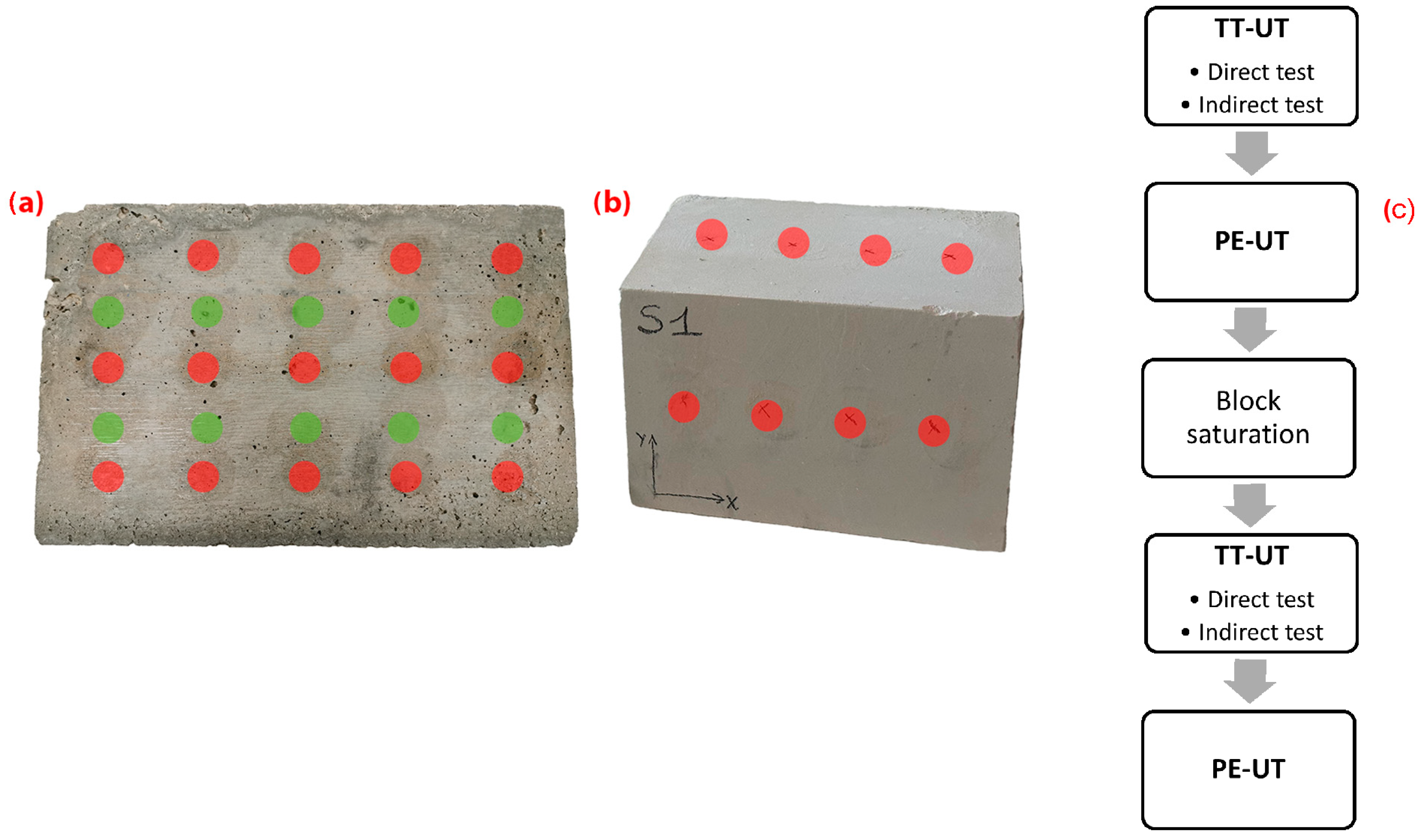
2.4. Specimen Dimensions and Testing Program

The concrete samples were six 30 × 20 × 12 cm blocks, while the Lecce stone samples were six 25 × 17 × 17 cm quarry blocks. The blocks were tested in ambient and saturated conditions. They were saturated by immersing them in water for one month.
TT-UT and PE-UT measurements were performed on concrete and stone blocks in ambient and saturated conditions. For each concrete block, fifteen measurement points were defined on the major faces (30 × 20 cm) to carry out fifteen direct transmission measures (Figure 2a, red dots). Two lines of five points were defined for the indirect ultrasonic measurements on the two major faces (Figure 2a, green dots). Thus, four indirect pulse velocities were obtained for each concrete block. A line of four measurement points on the major faces (25 × 17 cm) was defined for direct and indirect ultrasonic tests on stone blocks (Figure 1b). Thus, eight and four UPV values were obtained for each block in direct and indirect mode configurations. Three scans were performed on the major faces of each concrete and stone block with the PE-UT technique. The algorithm of the experimental tests performed on each block is reported in Figure 2c.

3. Results and Discussion

3.1. Through-Transmission Ultrasonic Tests

The 54 kHz exponential transducer results were compared to those of cylindrical ones. The transducers had the same frequency to evaluate the effect of the exponential tip on the results, avoiding the frequency influence. The results were compared considering direct and indirect transmission mode measurements.

3.1.1. Direct Transmission Mode

The results of the direct transmission measures are reported in Table 1. The exponential transducers measured UPV values lower than cylindrical ones in all the specimens, following literature results [20,21]. The reason was the lower power of the signal of exponential transducers and the consequent uncertainty of measurement in the presence of defects and inhomogeneities. In these cases, the shape of the onset of the pulse became more rounded, and consequently, higher transmission times were registered. This effect was proved by the different behavior observed in concrete and stone elements. Concrete elements embedded aggregates of a maximum diameter of 2 cm, while the maximum grain size of the Lecce stone was 2 mm. The higher compositeness of concrete than stone due to the presence of aggregates caused higher differences between UPV means of exponential and cylindrical transducers. The difference was 2.6% for stone and 4.4% for concrete in ambient conditions (Table 1). Furthermore, a higher coefficient of variation (CoV) for exponential transducers was obtained in concrete (5%) than in stone (2%).
The exponential transducer results varied less with water than cylindrical ones, causing an increase in the UPV mean difference in concrete and stone blocks (8.2% and 3.9%, respectively) (Table 1). In the case of concrete blocks, cylindrical and exponential transducer means were 15% and 11% higher in the presence of water, respectively. The water, substituting the air in the material porosity, caused UPV to increase in concrete blocks [8]. Variable values of UPV increase were obtained in the literature depending on the concrete porosity, and those obtained in the present research followed some of the literature results [28,29,30,31]. In the case of Lecce stone, there was a reduction in UPV due to water [2]. It was equal to 20% and 17% for cylindrical and exponential transducers, respectively. The UPV reduction is mostly due to clay minerals present in the Lecce stone. Water changes the structure of clay minerals with an expandable lattice by promoting swelling phenomena; ultrasonic velocity in expandable clay minerals is lower in wet conditions than in dry ones [32], and their presence in rocks contributes to the UPV decrease in saturated conditions [33]. This effect contrasts with the increase in the P-wave velocity in the pores filled by water, leading to the overall velocity decrease.

3.1.2. Indirect Transmission Mode

Indirect measurements were carried out on the casting surface of concrete blocks and the opposite one (smooth hereafter). The first had higher roughness than the second. Cylindrical transducers had worse contact with the casting surface than exponential ones because of their larger dimensions (3.7 cm). Indeed, considering the cylindrical transducer results, the measurements performed on the casting surfaces were more dispersed with higher registered transit times than those on the smooth surface at all measurement distances (Figure 3a). Exponential transducer results were more homogeneous, with comparable results and dispersions obtained on the two surfaces (Figure 3b). The roughness of the surface less influenced the results of exponential transducers, as expected, due to the low dimension of their contact point (0.4 cm).
The mean values of arrival times were calculated at each measurement distance and linearly correlated to obtain the UPV indirect results (Figure 4, Table 2), according to the procedure described in [26]. The slope of the linear correlation corresponded to the indirect UPV result.
The UPV of exponential transducers was 18% lower than that of cylindrical transducers (Figure 4a, Table 2). This difference was sensibly higher than that observed in direct mode measurements (4.4%). This was due to the lower power of the signal of the exponential transducer, which experienced higher attenuation over longer distances. Thus, the differences between the time means of the two transducers increased at higher path lengths, causing a lower slope and consequently a lower UPV value for exponential transducers.
Considering the casting and smooth surface data separately (Figure 4b), exponential transducer results were closer to those of cylindrical ones (15% lower) on the casting surface. The difference increased for the UPV means of the smooth surface (22%).
Indirect measurements were also performed on saturated blocks. A higher difference (24%) was obtained in saturated conditions between the two transducer results than in ambient conditions (18%) (Table 2). Water caused a reduction in registered times of wave arrival, independently of the type of transducer or the surface finishing (Figure 5). In the case of exponential transducers, there was a lower UPV increase due to water (4%) compared to cylindrical ones (12%) (Table 2). Indeed, the exponential transducers were less influenced by water than cylindrical ones, following the direct measurement results.
As for the measurement at ambient conditions, there was no significant difference between the measurement performed on the casting and smooth surfaces for exponential transducers (Figure 5b). The slope of the linear correlations did not change sensitively in the case of cylindrical transducers on the smooth surface (1%), and it increased by 15% on the casting surface (Figure 5a). Thus, the difference between the results obtained on the two surfaces was lower than in ambient conditions. This could be explained by the higher porosity of the casting surface than on the opposite side. The pores were filled with water, causing reduced arrival times, especially at longer path lengths.
In the case of Lecce stone, the higher homogeneity of the material and smoothness of the surfaces caused a lower dispersion of results with reduced standard deviations for cylindrical transducers than in concrete blocks (Figure 6a). UPV indirect values were obtained by linearly correlating the results at the different measuring points, following the procedure adopted for concrete (Figure 6b, Table 2). The UPV mean of the 54 kHz exponential transducers was 24% lower than cylindrical ones (Table 2). The result followed that obtained for concrete (22% on the smooth surface). It differed sensitively from those obtained for UPV measured in direct mode for exponential transducers (2.6%). Indeed, the differences between the arrival times increased with increasing distances due to higher attenuation of the signal at longer path lengths.
In the presence of water, the indirect ultrasonic velocities were reduced for both transducers (Table 2, Figure 7). The difference between the results of the two transducers increased in the presence of water, as in the case of concrete. In contrast with concrete, a higher variation with water was observed in exponential transducer results (24%) than in cylindrical ones (16%). The time readings of exponential transducers at the first distance were comparable in dry and saturated conditions, while they differed more at larger distances than for cylindrical transducers.
The differences in UPV variation with water between stones and concrete were due to a different mechanism that caused UPV variation. In the case of concrete, it was due to pore filling, which decreases the effect of inhomogeneities on exponential transducers, which were less affected by water than cylindrical transducers. In the case of stone, water influenced the material’s microstructure due to the swelling of clay minerals. This caused higher effects on exponential transducers than cylindrical ones at higher distances.

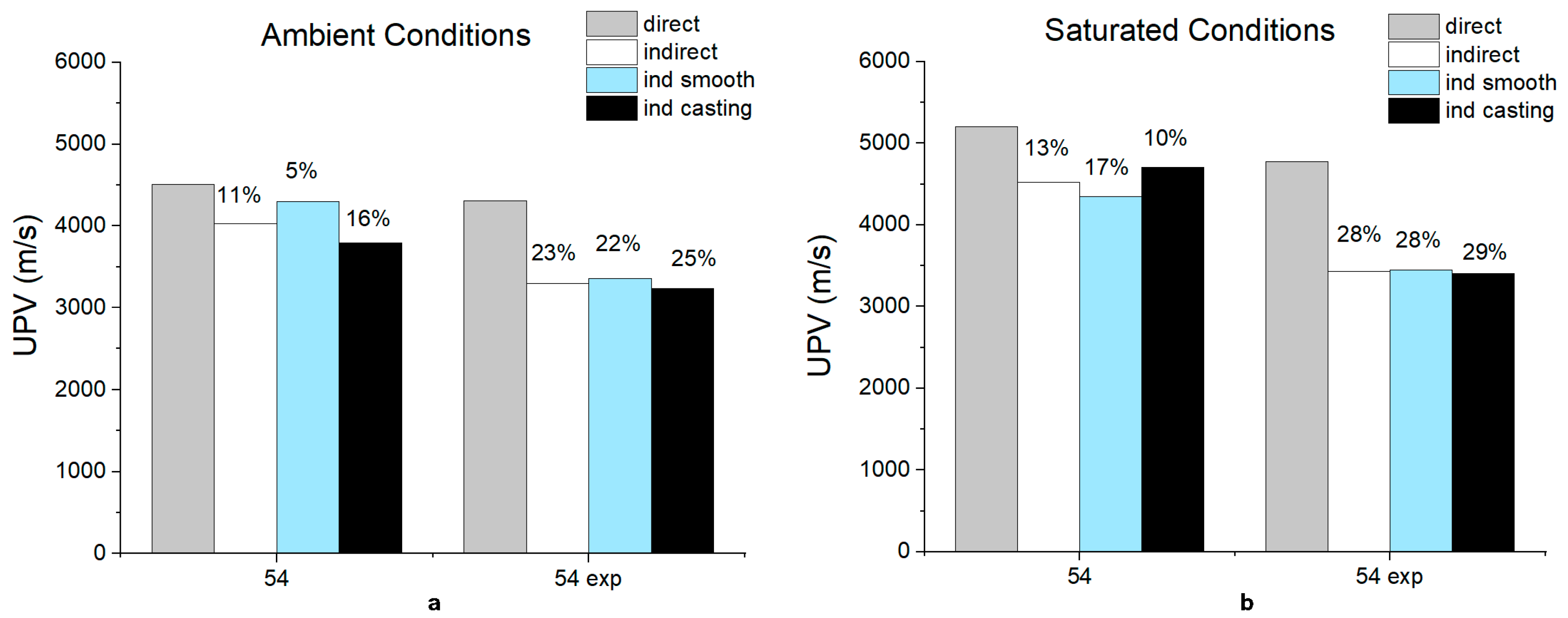
3.1.3. Comparison Between Indirect and Direct Transmission Mode Results

Direct and indirect transmission UPV results were compared for concrete and stone blocks (Figure 8 and Figure 9, respectively). It is known from literature that indirect measurement leads to unreliable results when the properties of the surface are different from those of the volume of the material [8].
Regarding concrete, the differences between indirect and direct results were higher for exponential transducers (22%) than for cylindrical ones (11%) (Figure 8a). The difference was 5% and 16% if casting and smooth surfaces were considered separately (Figure 8a). The results of 54 kHz cylindrical transducers could be regarded as reliable on the smooth surface because 5% is a value comparable with measurement variation. On the other hand, UPVs indirect results of casting surface were influenced by the surface roughness. Differences between direct and indirect results slightly increased in the presence of water from 11% to 13% (Figure 8b) for 54 kHz cylindrical transducers. Different behaviors were observed in UPV for casting and smooth surfaces. In the case of casting surface, the indirect results increased more than the direct ones in the presence of water, and their difference reduced from 16% to 10%. The opposite was for the smooth surface, passing from 5% to 17% difference. This circumstance depends on the higher content of voids and defects of the casting surface layers compared to the volume of the material, causing a higher increase in indirect results than direct ones in the presence of water [10]. The opposite was true for the smooth surface, which was more compact than the material in volume, causing a higher increase in direct UPV results than indirect ones. In the case of exponential transducers, the difference between direct and indirect test results increased with water independently of the surface tested.
In the case of Lecce stone, the difference between direct and indirect results of exponential transducers was the highest (Figure 9). It was 28% and 31%, respectively, in dry and saturated conditions. Cylindrical transducers used on Lecce stone in indirect mode gave results comparable to the direct ones in both saturated and dry conditions.
Thus, it can be concluded that exponential transducers gave unreliable results in the indirect mode independently of the material tested and surface conditions.

3.2. Pulse Echo Tomography Test Results

Impulse echo tomography measurements were performed on concrete and stone blocks. The instrument caused ultrasonic S-waves to travel within the object and returned an image obtained based on the SAFT algorithm. Starting with the tomographic image, ultrasonic velocity can be determined by knowing the thickness of the object investigated. Indeed, backwall echoes are evident in the tomographic images and represent the points where there is an interface between the material and the air (Figure 10). By fixing the depth of this interface corresponding to the object thickness, the instrument calibrates the ultrasonic velocity within the material. There are two ways of doing this operation. The first mode (Cal 1) is when only one backwall echo is visible, and the second one (Cal 2) is when two or more echoes are visible (Figure 10). The instrument can measure another S-wave velocity value when the object’s thickness is unknown. Indeed, it measures a superficial velocity (Sup), namely the pulse velocity of signals traveling near the object’s surface.
The superficial velocity results in concrete and stone blocks in ambient conditions were lower than both velocities determined with calibration modes (Figure 11). This was probably due to the different properties between the near-surface area and the volume, which also caused the UPV to vary. The higher difference was between superficial and Cal 2 velocities, especially in stone blocks (Table 3). A less accurate superficial velocity determination can be hypothesized in stone blocks because of the low value of UPV in stone. Indeed, the S-wave velocity of stone is closer to the full scale of the instrument (around 1100 m/s) than the UPV of concrete.
Differences between the velocities determined with the two calibration modes varied between 3% and 6% (Table 3) in dry conditions. To evaluate the significance of the result, the coefficient of variation of the measurement should be considered. In contrast with P-wave velocity measurements, the variation coefficient did not change when a more homogeneous material was considered. Velocity obtained with Cal 1 mode had a coefficient of variation of 3–4%. A slightly higher variability of results was obtained for those of the Cal 2 mode (4–7%) (Table 3). Thus, the differences between the values obtained by the two calibration modes were within the measurement variability.
The effect of water was to increase the S-wave velocity in concrete, as it was for P-wave velocities. The highest increase (6%) was obtained for superficial results, while the lowest was for Cal 1 results (3%) (Figure 11). Comparing the differences with those obtained for P-wave velocities, it can be concluded that S-waves were less sensitive to the presence of water [24]. The superficial velocity of the concrete blocks in saturated conditions was still lower than the Cal 1 and Cal 2 results. The instrument did not measure superficial velocity in the case of Lecce stone in saturated conditions. It was because the velocity values were under the full scale of the instrument. The Cal 2 mode was not used because only one backwall was visible due to the low velocity values in the presence of water, which caused attenuation of the signal. Thus, only the Cal 1 result was available for Lecce stone, and its value was lower than in dry conditions, following P-wave results.

Comparison Between Pulse-Echo and Through-Transmission Ultrasonic Test Results

Pulse echo tomography results were compared to direct (Table 1) and indirect (Table 2) transmission modes results. The comparison was possible by converting the S-wave velocity of PE-UT to P-wave velocities, knowing the Poisson’s ratio of the materials investigated. Indeed, it is known that S and P wave velocities can be used to determine the dynamic elastic constants of a linear elastic and isotropic material. In particular, the dynamic Poisson’s ratio (ν) is equal to
ν = V p 2 2 V s 2 2 ( V p 2 V s 2 )
Vp and Vs are the P and S wave velocities, respectively [34]. Knowing the S-wave velocity and the value of the dynamic Poisson’s ratio of the material, it is possible to determine the corresponding P-wave velocity and vice versa, based on Equation (1).
The relation (1) is valid for homogeneous and isotropic material. In the case of concrete or rocks, the type of experimental method used to determine Poisson’s ratio influences its value. It is known from the literature that Poisson’s ratio determined by Equation (1) differs from that calculated from static tests or impact resonance frequency tests [34,35,36,37]. It is widely accepted in the literature that the static Poisson’s ratio of concrete varies between 0.15 and 0.2 [38]; the latter is the value commonly used in design codes [39]. The dynamic Poisson’s ratio is generally greater than the static value. It is affected by many parameters like the presence of water, the aging of concrete, and the amount and type of aggregates [40,41].
A variability interval of Poisson’s ratio can be obtained from the literature, namely 0.15–0.25 and 0.2–0.3 for concrete and Lecce stone, respectively [35,40,41]. Thus, P-wave velocity can be estimated considering these intervals (Figure 12) starting from S-wave values and applying Equation (1). A maximum error in Vp estimation of 10% and 14% would result in the case of concrete and stone, respectively, due to an incorrect Poisson’s ratio estimation. Thus, a good Poisson’s ratio estimation is needed to obtain reliable P-wave velocity values starting from S-wave results.
Based on these considerations, an expeditious experimental survey was performed on four concrete cubic samples (10 cm side) of the same composition used for blocks. P- and S-wave velocity measurements were performed by direct mode using an Epoch 4 Plus (Olympus) instrument and P- and S-wave probes with a central frequency of 100 kHz. The value of Poisson’s ratio was estimated by applying Equation (1) to the results of the measurements. A value of 0.21 was obtained, comparable to that suggested by the pulse-echo instrument producer for good-quality concrete (User Manual Pundit PD 8050). The value fell within the literature interval of variation. The measurements were repeated on cubic samples in saturated conditions, and Poisson’s ratio of 0.29 was found. Similar measurements were performed in a previous experimental campaign in our laboratories on Lecce stone cubic samples (7 cm side) [42], and values of 0.23 and 0.25 were obtained in dry and saturated conditions.
It was possible to estimate P-wave velocities starting from S-wave velocities obtained with superficial, Cal 1, and 2 modes by applying the obtained Poisson’s ratio values. In particular, the P-wave velocities obtained using S-wave Sup (Vps) were compared to the results of indirect transmission measurements. Cal 1 (Vp_cal1) and Cal 2 (Vp_cal2) P-wave velocities were compared to direct transmission results by different transducer types (Figure 13, Table 4).
Considering concrete blocks, P-wave velocities obtained with Cal 1 mode differed by 2–7% from direct transmission velocities. The differences were lower if Cal 2 velocities were considered (1–3%). In the case of stone blocks, the differences were 3–4% and 0–2% for Vp_cal1 and Vp_cal2 velocities, respectively. Thus, for both materials, the Cal 2 mode better fit the results of direct transmission.
Superficial wave results were in line with the 54 kHz indirect measurement in the case of concrete. In the case of stone, the differences increased to unacceptable values (10%). It was probably because of the low velocity values registered by the superficial mode in Lecce stone, which were near the full scale of the instrument, causing an increased error in UPV estimation. Exponential transducer results differed from the superficial P-wave velocities obtained with the pulse-echo instrument for both concrete and stone.
As expected, a higher value of Poisson’s ratio was obtained for saturated concrete [40,41], equal to 0.29. The P-wave velocities obtained from pulse-echo S-wave measurements were compared with direct and indirect P-wave measurements (Figure 14, Table 5). Cal 2 results fit better than Cal 1, the results of 54 kHz cylindrical transducers (7% and 1%, respectively). The opposite was for exponential transducer results. It is because Cal 1 results are lower than Cal 2, being closer to exponential transducer results. Superficial mode results were comparable to 54 kHz cylindrical transducers’ results in indirect mode (2% difference), while they strongly differed from the results of exponential transducers.
Poisson’s ratio of Lecce stone in saturated conditions was equal to 0.25. The difference between Vp_cal1 and direct transmission results was 2%. Thus, it followed both cylindrical and exponential transducer results.

4. Conclusions

One of the most important limitations in performing ultrasonic pulse velocity on building materials on-site is the one-sided accessibility of materials and the presence of degraded and irregular surfaces. In this regard, pulse-echo tomography can be used to overcome the problem. There are few works in the literature on the reliability of this technique in the UPV assessment of building materials. In the paper, the results of UPV measurements, performed with the PE-UT and TT-UT, were compared. Exponential and cylindrical transducers of the same frequency were used for TT-UT measurements. Exponential transducers are widely used on-site when cylindrical ones cannot be used, as in the case of degraded, irregular, or rounded surfaces, or when the coupling gel is forbidden, as in architectural heritage. On the other hand, few works in the literature compare the results of cylindrical and exponential transducers to evaluate their reliability. This is another element of novelty of the paper.
Comparing the results of exponential and cylindrical transducers, it was found that
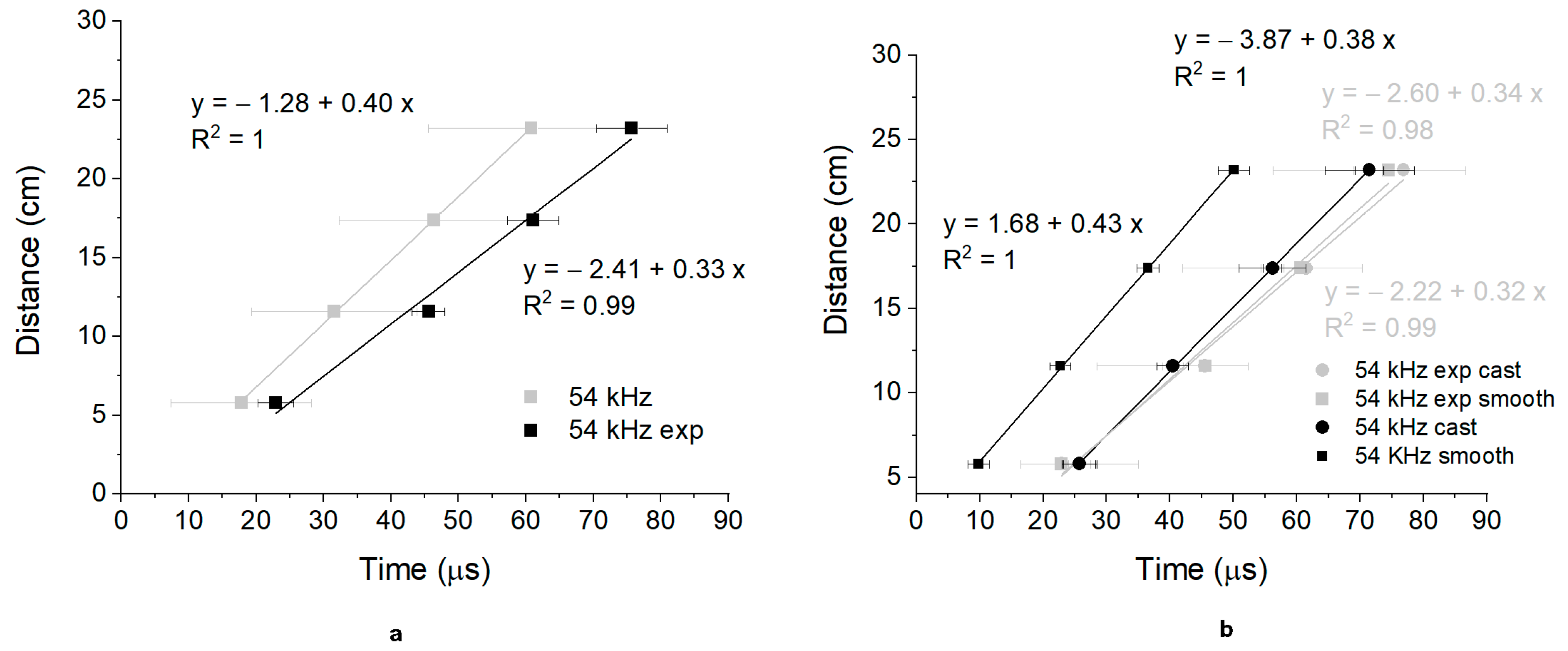
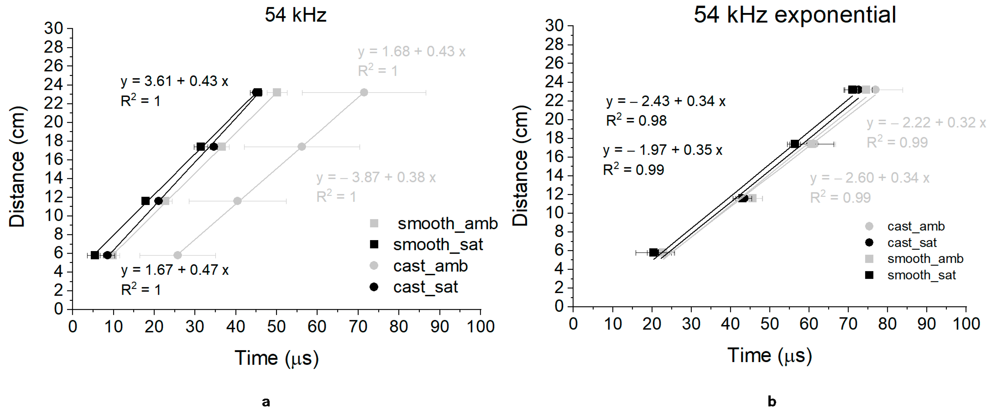
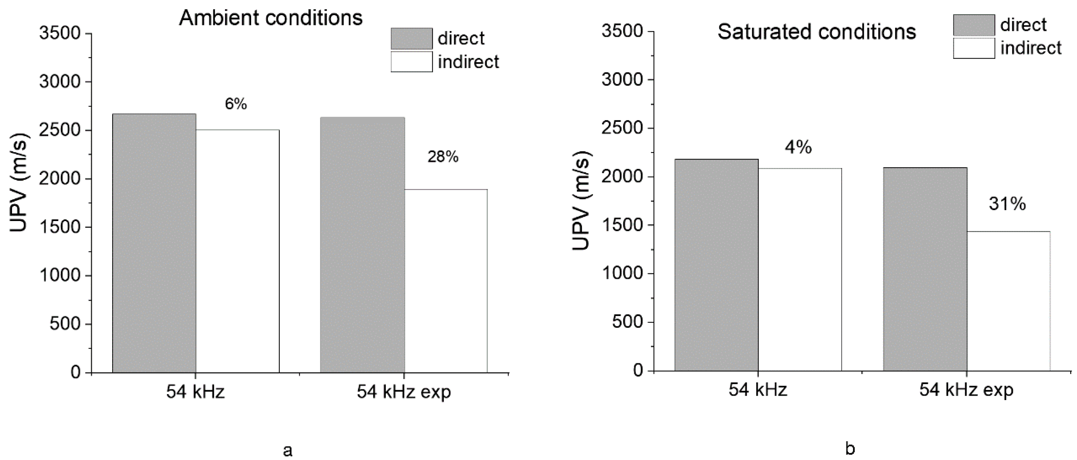
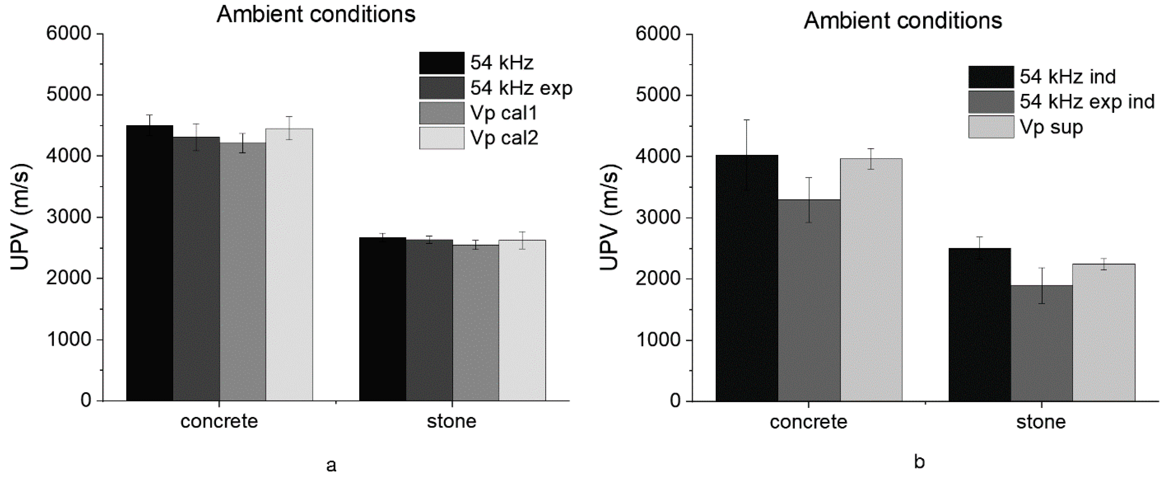
  • Exponential transducer results were less affected by water and surface roughness than the cylindrical transducer in direct transmission mode. On the other hand, the lower power of the signal due to the presence of the exponential tip caused measurement uncertainty, especially in concrete. Differences between UPV of exponential and cylindrical transducers were higher in concrete (4.4%) than in stone (2.6%).
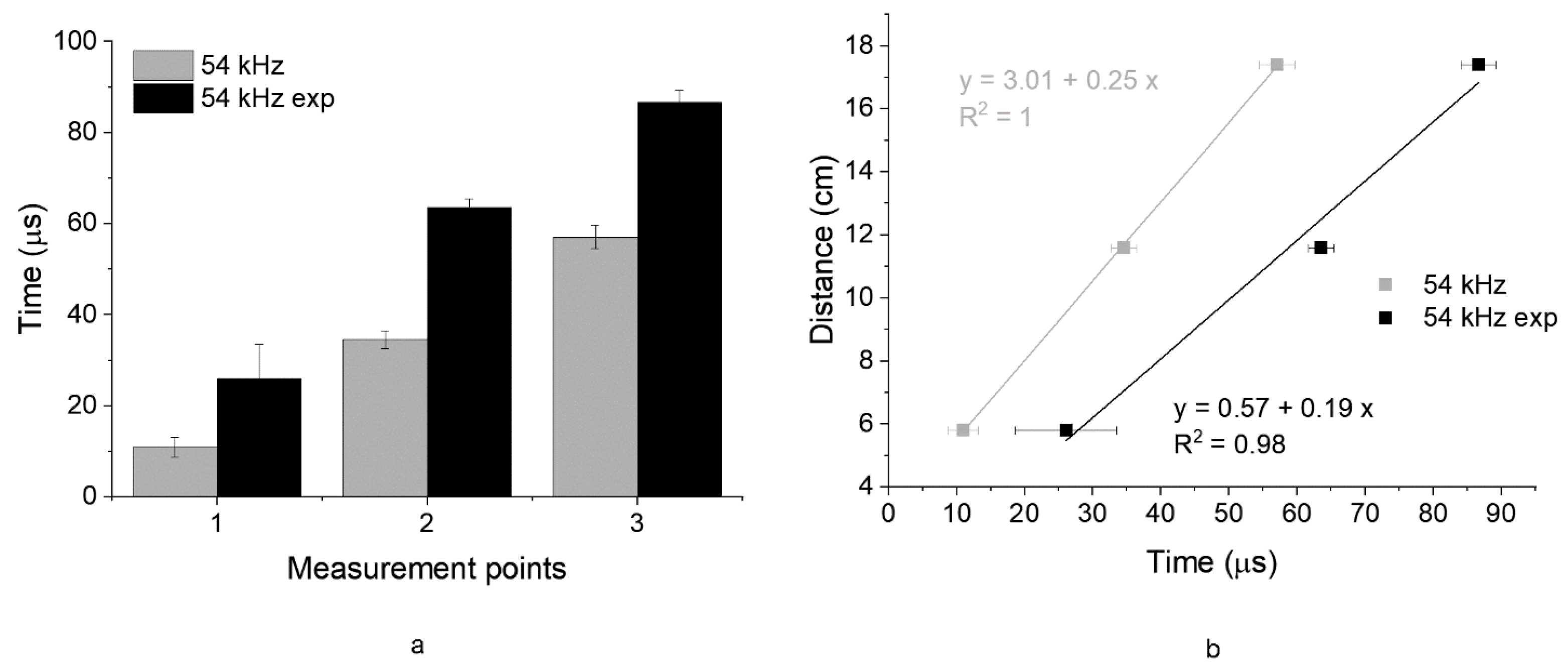
  • In the case of indirect measurements, exponential transducers experienced higher attenuation of the signal over higher distances than cylindrical ones. Thus, differences between the time means of the two transducers increased at higher path lengths, causing a lower indirect UPV value for exponential transducers than cylindrical ones (differences in results of 24% and 22% for stone and concrete, respectively).
  • By comparing the results of UPV measured by direct and indirect transmission modes, it was found that exponential transducers gave unreliable results in the indirect mode independently of the material tested. Indeed, differences between 23% and 29% were found between the results of the two measurement modes.
Regarding PE-UT measurements, three modes were used to determine the S-wave velocities. The superficial mode investigated the most superficial layers of the material. Cal 1 and Cal 2 velocities were determined by fixing the thickness of the specimen using one back wall or more back walls, respectively, in the images. From the experiments, it was found that
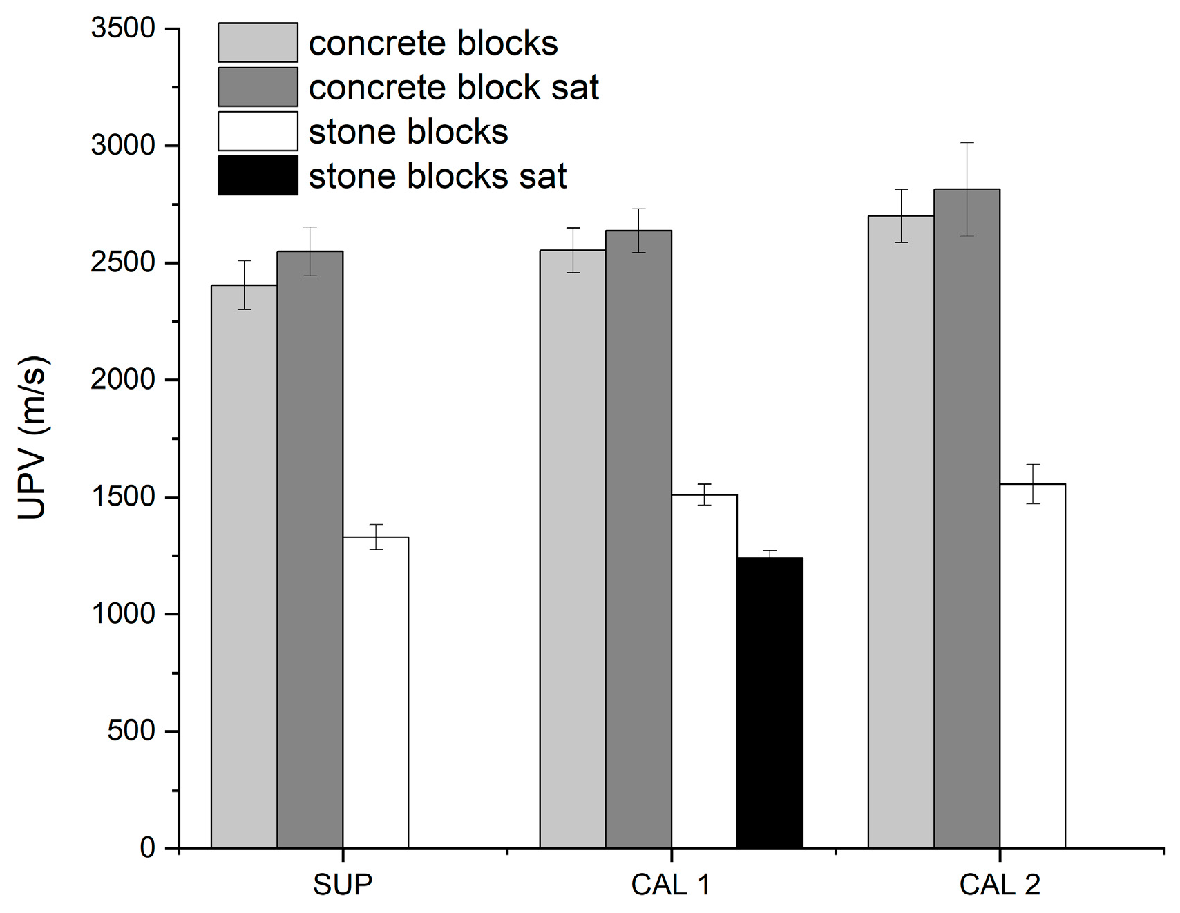
  • The superficial velocities were lower than those obtained by the calibration mode for both concrete and stone specimens.
  • The differences between the UPV values obtained by the two calibration modes were within the measurement variability.
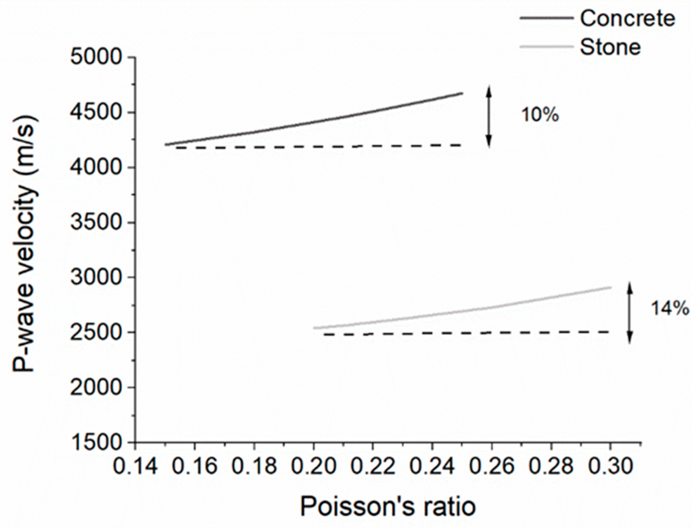
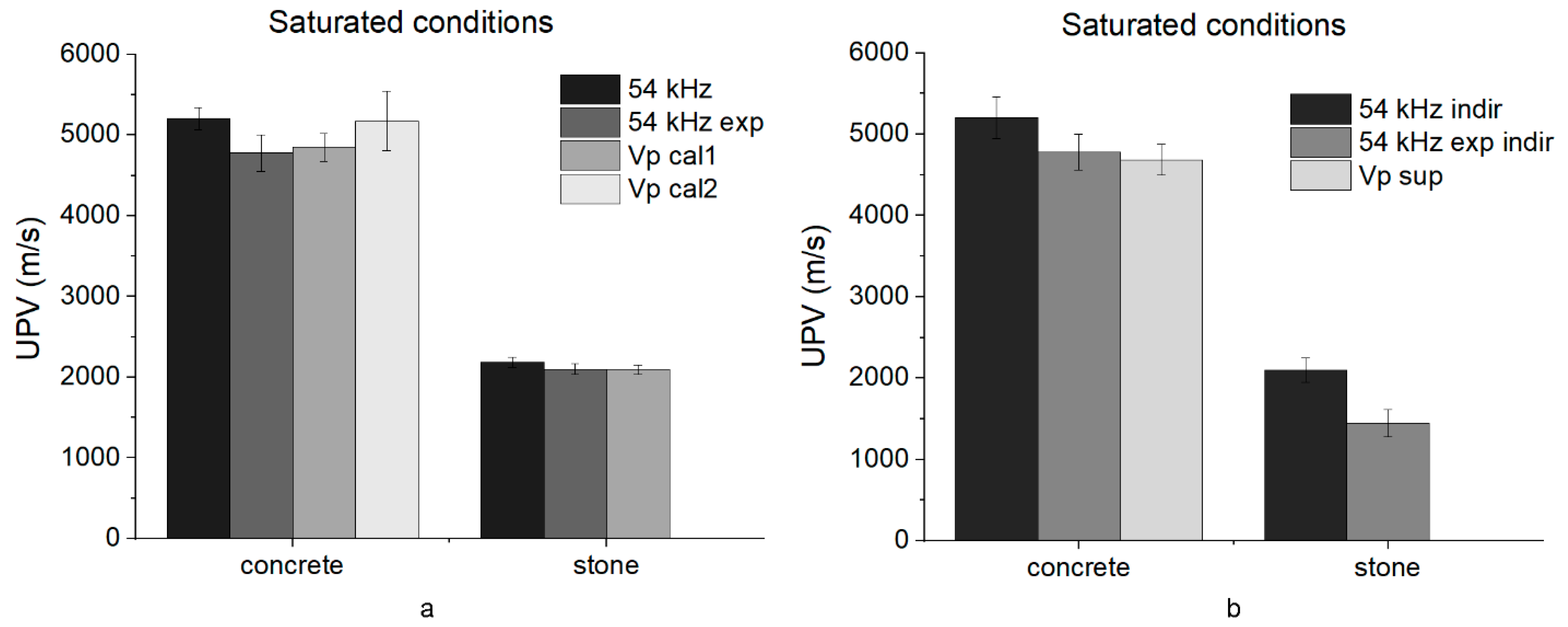
  • The presence of water increased the S-wave velocities in concrete, but less than the P-wave velocities. The superficial velocity of the concrete blocks in saturated conditions was still lower than the Cal 1 and Cal 2 results.
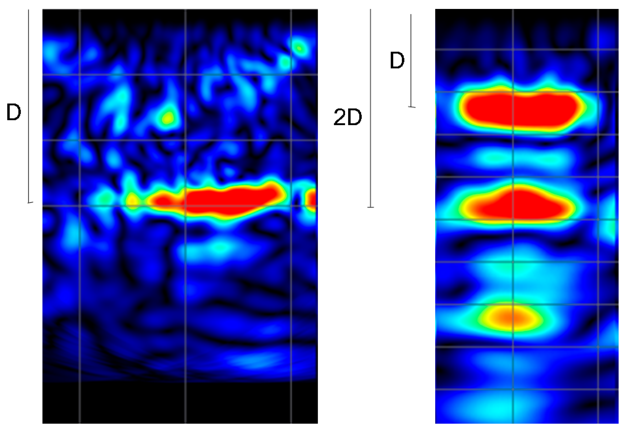
  • In the case of Lecce stone in saturated conditions, the instrument did not measure superficial velocity because its value was below the full scale of the instrument. Furthermore, only one backwall was visible in the tomographic image. Thus, only the calibration 1 result was available, and its value was lower than in dry conditions, following the P-wave results.
P-wave velocities were estimated starting from superficial Cal 1, and Cal 2 S-wave velocities, knowing Poisson’s ratio of the materials investigated. By comparing the results of PE-UT and TT-UT, it was found that
  • Cal 2 mode velocities better fit than Cal 1 mode the direct transmission results of concrete with and without water. Furthermore, superficial wave results followed those of the 54 kHz indirect measurement.
  • In the case of stone in ambient conditions, the Cal 2 results fit better than Cal 1 with the results of the direct transmission mode. Superficial mode results differed from the indirect transmission ones of unacceptable values for both transducers. Probably, the superficial mode was inaccurate in the case of Lecce stone due to velocity values near the full scale of the instrument. The results in the presence of water were comparable to TT-UT in direct mode.
  • Exponential transducer results in indirect transmission mode significantly differed from the superficial P-wave velocities obtained with the pulse-echo instrument. The results confirmed the previous conclusions on indirect mode results using these transducers.
The experimental results confirmed that the impulse-echo technique could be employed for UPV measurements based on imaging results. Thus, the method allows for rapid and reliable one-sided tests on building materials. The limitation of the technique lies in the impossibility of testing building materials of low ultrasonic velocity (lower than 1000 m/s). More research is needed to investigate the instrument performance in the presence of rebars within concrete and plaster. Furthermore, the influence of concrete composition (aggregate dimension, type of cement, and water-cement ratio) on PE-UT results should be further explored in the future.

Author Contributions

Conceptualization, E.V.; methodology, E.V. and L.C.; validation, E.V., L.C. and G.B.; formal analysis, E.V.; investigation, D.D.G., M.S. and E.V.; resources, L.C.; data curation, D.D.G., M.S. and E.V.; writing—original draft preparation, E.V.; writing—review and editing, E.V., D.D.G., M.S., L.C. and G.B.; funding acquisition, L.C. and E.V. All authors have read and agreed to the published version of the manuscript.

Funding

Authors acknowledge financial support under the National Recovery and Resilience Plan (NRRP), Mission 4, Component 2, Investment 1.1, Call for Tender No. 104 published on 2 February 2022 by the Italian Ministry of University and Research (MUR), funded by the European Union—NextGenerationEU—Project Title ICARUS (Multiscale integrated approach for the deterioration assessment of reinforced concrete structures)—CUP B53D23005520006—Grant Assignment Decree No. 961 adopted on 30 June 2023 by the Italian Ministry of University and Research (MUR). The publication has been funded by EU—Next Generation EU Mission 4, Component 2—CUP B53C22002150006—Project IR0000032—ITINERIS—Italian Integrated Environmental Research Infrastructures System.

Data Availability Statement

The raw data supporting the conclusions of this article will be made available by the authors on request.

Conflicts of Interest

The authors declare no conflicts of interest. The funders had no role in the design of the study; in the collection, analyses, or interpretation of data; in the writing of the manuscript; or in the decision to publish the results.

List of Abbreviations

UPVUltrasonic Pulse Velocity
PE-UTPulse Echo Ultrasonic Tomography
TT-UTThrough Transmission Ultrasonic Test
Δ (cyl-exp)difference between the UPV values of cylindrical and exponential transducers
VpP-wave velocity
VsS-wave velocities
Vp_cal1PE-UT P-wave velocity results from calibration 1 measurements
Vp cal2PE-UT P-wave velocity results from calibration 2 measurements
Vp supPE-UT P-wave velocity results from superficial measurements

References

  1. McCann, D.; Forde, M. Review of NDT methods in the assessment of concrete and masonry structures. NDT & E Int. 2001, 34, 71–84. [Google Scholar] [CrossRef]
  2. Vasanelli, E.; Colangiuli, D.; Calia, A.; Sileo, M.; Aiello, M.A. Ultrasonic pulse velocity for the evaluation of physical and mechanical properties of a highly porous building limestone. Ultrasonics 2015, 60, 33–40. [Google Scholar] [CrossRef]
  3. Breysse, D.; Balayssac, J.-P.; Alwash, M.; Biondi, S.; Chiauzzi, L.; Corbett, D.; Garnier, V.; Gonçalves, A.; Grantham, M.; Gunes, O.; et al. In-situ strength assessment of concrete: Detailed guidelines. In Non-Destructive In Situ Strength Assessment of Concrete: Practical Application of the RILEM TC 249-ISC Recommendations; Springer: Cham, Switzerland, 2021; pp. 3–56. [Google Scholar] [CrossRef]
  4. Saleem, M.; Gutierrez, H. Using artificial neural network and non-destructive test for crack detection in concrete surrounding the embedded steel reinforcement. Struct. Concr. 2021, 22, 2849–2867. [Google Scholar] [CrossRef]
  5. Karaiskos, G.; Deraemaeker, A.; Aggelis, D.G.; Van Hemelrijck, D. Monitoring of concrete structures using the ultrasonic pulse velocity method. Smart Mater. Struct. 2015, 24, 113001. [Google Scholar] [CrossRef]
  6. Lee, J.H.; Park, W.S.; Popovics, J.S.; Achenbach, J.D. Application of one-sided stress wave velocity measurement technique to evaluate freeze-thaw damage in concrete. Rev. Prog. Quant. Nondestruct. Eval. 1999, 18A–18B, 1935–1942. [Google Scholar]
  7. Yaman, I.O.; Inci, G.; Yesiller, N.; Aktan, H.M. Ultrasonic pulse velocity in concrete using direct and indirect transmission. ACI Mater. J. 2001, 98, 450. [Google Scholar]
  8. Malhotra, V.M.; Carino, N.J. Handbook on Nondestructive Testing of Concrete; CRC Press: Boca Raton, FL, USA, 2003. [Google Scholar]
  9. Turgut, P.; Kucuk, O.F. Comparative relationships of direct, indirect, and semi-direct ultrasonic pulse velocity measurements in concrete. Russ. J. Nondestruct. Test. 2006, 42, 745–751. [Google Scholar] [CrossRef]
  10. Biondi, S.; Valente, C.; Zuccarino, L. Concrete Strength Evaluation through indirect UPV. In Proceedings of the Concrete Solutions, 5th International Conference on Concrete Repair, Belfast, UK, 1–3 September 2014; pp. 771–778. [Google Scholar] [CrossRef]
  11. Lee, C.H.; Jo, Y.H. Correlation and correction factor between direct and indirect methods for the ultrasonic measurement of stone samples. Environ. Earth Sci. 2017, 76, 477. [Google Scholar] [CrossRef]
  12. Chai, H.K.; Momoki, S.; Kobayashi, Y.; Aggelis, D.G.; Shiotani, T. Tomographic reconstruction for concrete using attenuation of ultrasound. NDT & E Int. 2011, 44, 206–215. [Google Scholar] [CrossRef]
  13. Silva, F.A.; Nogueira, C.L.; Silva, J.A.; Araújo, A.V.; Azevedo, A.C.; Delgado, J.M. Ultrasonic assessment of damage in concrete under compressive and thermal loading using longitudinal and transverse waves. Russ. J. Nondestruct. Test. 2019, 55, 808–816. [Google Scholar] [CrossRef]
  14. De La Haza, A.O.; Samokrutov, A.A.; Samokrutov, P.A. Assessment of concrete structures using the Mira and Eyecon ultrasonic shear wave devices and the SAFT-C image reconstruction technique. Constr. Build. Mater. 2013, 38, 1276–1291. [Google Scholar] [CrossRef]
  15. Wang, Q.; Chen, D.; Zhu, K.; Zhai, Z.; Xu, J.; Wu, L.; Hu, D.; Xu, W.; Huang, H. Evaluation Residual Compressive Strength of Tunnel Lining Concrete Structure after Fire Damage Based on Ultrasonic Pulse Velocity and Shear-Wave Tomography. Processes 2022, 10, 560. [Google Scholar] [CrossRef]
  16. Kwon, H.; Joh, C.; Chin, W.J. 3D Internal Visualization of Concrete Structure Using Multifaceted Data for Ultrasonic Array Pulse-Echo Tomography. Sensors 2021, 21, 6681. [Google Scholar] [CrossRef]
  17. Ivanchev, I. Experimental determination of dynamic modulus of elasticity of concrete with ultrasonic pulse velocity method and ultrasonic pulse echo method. IOP Conf. Ser. Mater. Sci. Eng. 2022, 1252, 012018. [Google Scholar] [CrossRef]
  18. Felicetti, R. Assessment of a fire-damaged concrete overpass: The Verona bus crash case study. J. Struct. Fire Eng. 2022, 13, 293–306. [Google Scholar] [CrossRef]
  19. Abreu Filho, M.A.; Moreno, C.; Luso, E. The Use of Ultrasonic Echo Pulse Velocity as an NDT Method to Predict the Concrete Strength and Uniformity. Russ. J. Nondestruct. Test. 2022, 58, 277–288. [Google Scholar] [CrossRef]
  20. Gudra, T.; Stawiski, B. Non-destructive strength characterization of concrete using surface waves. NDT & E Int. 2000, 33, 1–6. [Google Scholar] [CrossRef]
  21. Stawiski, B.; Kania, T. Tests of Concrete Strength across the Thickness of Industrial Floor Using the Ultrasonic Method with Exponential Spot Heads. Materials 2020, 13, 2118. [Google Scholar] [CrossRef]
  22. Hager, I.; Carré, H.; Krzemień, K. Damage assessment of concrete subjected to high temperature by means of the ultrasonic pulse velocity–UPV method. Stud. Res. 2013, 32, 197–211. [Google Scholar]
  23. UNI EN 197-1:2011; Cement—Part 1: Composition, Specifications and Conformity Criteria for Common Cements. European Committee for Standardization: Brussels, Belgium, 2011.
  24. UNI EN 12390-3:2019; Testing Hardened Concrete—Part 3: Compressive Strength of Test Specimens. European Committee for Standardization: Brussels, Belgium, 2019.
  25. Calia, A.; Tabasso, M.L.; Mecchi, A.M.; Quarta, G. The study of stone for conservation purposes: Lecce stone (southern Italy). Geol. Soc. Lond. Spéc. Publ. 2014, 391, 139–156. [Google Scholar] [CrossRef]
  26. UNI EN 12504-4:2005; Testing Concrete—Part 4: Determination of Ultrasonic Pulse Velocity. European Committee for Standardization: Brussels, Belgium, 2005.
  27. Schickert, M.; Krause, M.; Müller, W. Ultrasonic Imaging of Concrete Elements Using Reconstruction by Synthetic Aperture Focusing Technique. J. Mater. Civ. Eng. 2003, 15, 235–246. [Google Scholar] [CrossRef]
  28. Candelaria, M.D.E.; Kee, S.-H.; Yee, J.-J.; Lee, J.-W. Effects of Saturation Levels on the Ultrasonic Pulse Velocities and Mechanical Properties of Concrete. Materials 2020, 14, 152. [Google Scholar] [CrossRef] [PubMed]
  29. Yaman, I.O.; Hearn, N.; Aktan, H.M. Active and non-active porosity in concrete Part I: Experimental evidence. Mater. Struct. 2002, 35, 102–109. [Google Scholar] [CrossRef]
  30. Güneyli, H.; Karahan, S.; Güneyli, A.; Yapιcι, N. Water content and temperature effect on ultrasonic pulse velocity of concrete. Russ. J. Nondestruct. Test. 2017, 53, 159–166. [Google Scholar] [CrossRef]
  31. Godinho, J.P.; Júnior, T.F.D.S.; Medeiros, M.H.F.; Silva, M.A. Factors influencing ultrasonic pulse velocity in concrete. Rev. IBRACON Estruturas Mater. 2020, 13, 222–247. [Google Scholar] [CrossRef]
  32. Basma, A.A.; Al-Homoud, A.S.; Malkawi, A.I.H.; Al-Bashabsheh, M.A. Swelling-shrinkage behavior of natural expansive clays. Appl. Clay Sci. 1996, 11, 211–227. [Google Scholar] [CrossRef]
  33. Karakul, H.; Ulusay, R. Empirical Correlations for Predicting Strength Properties of Rocks from P-Wave Velocity Under Different Degrees of Saturation. Rock Mech. Rock Eng. 2013, 46, 981–999. [Google Scholar] [CrossRef]
  34. Pal, P. Dynamic poisson’s ratio and modulus of elasticity of pozzolana Portland cement concrete. Int. J. Eng. Technol. Innov. 2019, 9, 131–144. [Google Scholar]
  35. Shen, S.; Gao, Y.; Jia, L. A Comparison of the Relationship between Dynamic and Static Rock Mechanical Parameters. Appl. Sci. 2024, 14, 4487. [Google Scholar] [CrossRef]
  36. Popovics, S. Verification of relationships between mechanical properties of concrete-like materials. Mat. Constr. 1975, 8, 183–191. [Google Scholar] [CrossRef]
  37. Andayani, S.W.; Suratman, R.; Imran, I. Mardiyati Polymer Modified Concrete of Blended Cement and Natural Latex Copolymer: Static and Dynamic Analysis. Open J. Civ. Eng. 2018, 8, 205–220. [Google Scholar] [CrossRef]
  38. Anson, M.; Newman, K. The effect of mix proportions and method of testing on Poisson’s ratio for mortars and concretes. Mag. Concr. Res. 1966, 18, 115–130. [Google Scholar] [CrossRef]
  39. Model Code 2010-First Complete Draft-Volume 2: Model Code; FIB (Fédération Internationale du Béton): Lausanne, Switzerland, 2010.
  40. Swamy, R.N. Dynamic Poisson’s ratio of portland cement paste, mortar and concrete. Cem. Concr. Res. 1971, 1, 559–583. [Google Scholar] [CrossRef]
  41. Ahmed, L. Dynamic Measurements for Determining Poisson’s Ratio of Young Concrete. Nord. Concr. Res. 2018, 58, 95–106. [Google Scholar] [CrossRef]
  42. Sileo, M. Individuazione e Caratterizzazione Geologica, Chimico-Mineralogica e Petrofisica di Calcareniti Tenere della Puglia e della Basilicata in Relazione alle Problematiche di Provenienza e Conservazione dei Beni Culturali; Basilicata University–IBAM (Institute of Archaeological and Monumental Heritage), CNR: Matera, Italy, 2012. (In Italian) [Google Scholar]
Figure 1. Ultrasonic measurement with PE-UT (a), TT-UT direct (b), and indirect (c) transmission modes. Stone blocks are illustrated as an example to show the different measurement techniques.
Infrastructures 10 00162 g001
Figure 2. (a) Measuring points on concrete blocks: direct transmission measurement points are in red, and indirect ones are in green. (b) Measuring points on Lecce stone blocks. (c) Algorithm of the experimental campaign on each block.
Infrastructures 10 00162 g002
Figure 3. Time readings at measurement points of concrete blocks, using 54 kHz cylindrical (a) and exponential (b) transducers. Data are reported considering casting and smooth surfaces together (all) and separately (smooth and casting).
Infrastructures 10 00162 g003
Figure 4. (a) Linear correlations between measuring point distances and time readings for 54 kHz cylindrical (54 kHz) and exponential transducers (54 kHz exp). (b) Results of casting (cast) and smooth surfaces. The slopes of the lines are the indirect ultrasonic velocities of 54 kHz cylindrical and exponential transducers (cm/μs).
Infrastructures 10 00162 g004
Figure 5. Linear correlations between measuring point distances and time readings for 54 KHz cylindrical (a) and exponential (b) transducers on smooth and casting (cast) surfaces in ambient (amb) and saturated (sat) conditions. The slopes of the lines are the indirect ultrasonic velocities (cm/μs).
Infrastructures 10 00162 g005
Figure 6. Time readings at each measurement point of Lecce stone for 54 kHz cylindrical transducers (54 kHz) and 54 kHz exponential (54 kHz exp) transducers (a). Linear correlations between measuring point distances and time readings for exponential and cylindrical transducers (b).
Infrastructures 10 00162 g006
Figure 7. Linear correlations between measuring point distances and time readings for 54 KHz cylindrical and exponential transducers in ambient (amb) and saturated (sat) conditions for Lecce stone. The slopes of the lines are the indirect ultrasonic velocities (cm/μs).
Infrastructures 10 00162 g007
Figure 8. Comparison between direct and indirect transmission UPV results of concrete blocks in ambient (a) and saturated (b) conditions. Results of indirect measurements are reported considering the smooth (ind smooth) and casting (ind casting) surfaces separately and together (indirect).
Infrastructures 10 00162 g008
Figure 9. Comparison between direct and indirect UPV results of stone blocks in ambient (a) and saturated (b) conditions.
Infrastructures 10 00162 g009
Figure 10. Tomographic image examples with one backwall and two backwalls at object thickness D.
Infrastructures 10 00162 g010
Figure 11. S-wave velocity obtained by superficial (SUP), calibration 1 (CAL 1), and calibration 2 (CAL 2) measurement modes for concrete and stone blocks in ambient and saturated (sat) conditions.
Infrastructures 10 00162 g011
Figure 12. P-wave velocity variation with Poisson’s ratio by applying Equation (1) starting from Cal 2 S-wave velocities. Dotted lines are drawn to evidence the maximum variability in P-wave velocity by varying the Poisson’s ratio in the ranges of 0.15–0.25 and 0.2–0.3 for concrete and Lecce stone, respectively.
Infrastructures 10 00162 g012
Figure 13. P-wave velocity comparison among TT-UT direct measurements and PE-UT results from Cal 1 (Vp cal1) and Cal 2 (Vp cal2) in ambient conditions (a). P-wave velocity comparison among TT-UT indirect measurements and PE-UT results from superficial (Vp sup) mode in ambient conditions (b).
Infrastructures 10 00162 g013
Figure 14. P-wave velocity comparison among TT-UT direct measurements and PE-UT results from Cal 1 (Vp cal1) and Cal 2 (Vp cal2) in saturated conditions (a). P-wave velocity comparison among TT-UT indirect measurements and PE-UT results from superficial (Vp sup) mode in saturated conditions (b).
Infrastructures 10 00162 g014
Table 1. Mean values (coefficient of variation%) of UPV measurements performed with cylindrical (54 kHz) and exponential (54 kHz exp) transducers in ambient and saturated conditions. The difference between the UPV values of cylindrical and exponential transducers (Δ (cyl-exp)) is reported in the last row of the table.
Concrete Blocks AmbientConcrete Blocks SaturatedStone Blocks AmbientStone Block Saturated
54 kHz4510 (4%)5204 (3%)2671 (3%)2183 (3%)
54k Hz exp4310 (5%)4777 (5%)2601 (2%)2100 (4%)
Δ (cyl-exp)4.4%8.2%2.6%3.9%
Table 2. Mean values (coefficient of variation%) of UPV measurement performed in indirect mode with cylindrical (54 kHz) and exponential (54 kHz exp) transducers in ambient and saturated conditions. The difference between the UPV values of cylindrical and exponential transducers (Δ (cyl-exp)) is reported in the last row of the table.
Concrete Blocks AmbientConcrete Blocks SaturatedStone Blocks AmbientStone Block Saturated
54 kHz4032 (14%)4523 (6%)2506 (7%)2091 (7%)
54 kHz exp3297 (11%)3432 (6%)1893 (15%)1442 (11%)
Δ (cyl-exp)18%24%24%31%
Table 3. Differences in S-wave velocity results between superficial (Sup), calibration 1 (Cal 1), and calibration 2 (Cal 2) measurement modes. The results’ coefficient of variation (CoV) is reported in the lower part of the table for the different measurement modes.
Concrete Blocks AmbientStone Blocks AmbientConcrete Blocks SaturatedStone Blocks Saturated
UPV difference (%)
Sup-Cal 1−6−14−4-
Sup-Cal 2−12−17−10-
Cal 1-Cal 2−6−3−7-
CoV (%)
Sup444-
Cal 14433
Cal 2476
Table 4. Differences in P-wave velocity results between direct and indirect (ind) TT-UT and PE-UT superficial (Vps), calibration 1 (Vp_cal1), and calibration 2 (Vp_cal2) measurement modes for concrete and stone blocks in ambient conditions.
Concrete Blocks Ambient
Cal 1Cal 2Sup
54 kHz-Vp_cal17%54 kHz-Vp_cal21%54 kHz ind-Vps2%
54 kHz exp-Vp_cal12%54 kHz exp-Vp_cal2−3%54 kHz exp ind-Vps−20%
Stone Blocks Ambient
Cal 1Cal 2Sup
54 kHz-Vp_cal14%54 kHz-Vp_cal22%54 kHz ind-Vps10%
54 kHz exp-Vp_cal13%54 kHz exp-Vp_cal20%54 kHz exp ind-Vps−19%
Table 5. Differences in P-wave velocity results between direct and indirect (ind) transmission mode and PE-UT superficial (Vps), calibration 1 (Vp cal1), and calibration 2 (Vp cal2) modes for concrete blocks in saturated conditions.
Concrete Blocks Saturated
Cal 1Cal 2Sup
54 kHz-Vp_cal17%54 kHz-Vp_cal21%54 kHz ind-Vps2%
54 kHz exp-Vp_cal1−1%54 kHz exp-Vp_cal2−8%54 kHz exp-Vps−20%
Stone Blocks Saturated
Cal 1Cal 2Sup
54 kHz-Vp_cal12%54 kHz-Vp_cal2-54 kHz ind-Vps-
54 kHz exp-Vp_cal1−2%54 kHz exp-Vp_cal2-54 kHz exp-Vps-
Disclaimer/Publisher’s Note: The statements, opinions and data contained in all publications are solely those of the individual author(s) and contributor(s) and not of MDPI and/or the editor(s). MDPI and/or the editor(s) disclaim responsibility for any injury to people or property resulting from any ideas, methods, instructions or products referred to in the content.

