Article

Assessment of the Residual Life of the Repaired Arousa Bridge

by
José Antonio Becerra-Mosquera
1,
Diego Carro-López
2,*,
Manuel F. Herrador
2 and
Javier Eiras-López
2
1
Neto Structure & Heavy Lift Design, 15683 A Coruña, Spain
2
CITEEC (Centro de Innovación Tecnolóxica en Edificación e Enxeñería Civil), Universidade da Coruña, 15008 A Coruña, Spain
*
Author to whom correspondence should be addressed.
Infrastructures 2025, 10(6), 141; https://doi.org/10.3390/infrastructures10060141
Submission received: 5 May 2025 / Revised: 1 June 2025 / Accepted: 4 June 2025 / Published: 6 June 2025
(This article belongs to the Special Issue Structural Health Monitoring in Bridge Engineering)

Abstract

This study focuses on the evolution of the Arousa Island Bridge, a critical infrastructure connecting, in northwestern Spain, the Arousa island to the Galician coast. Since its commissioning in 1985, the bridge has experienced damage due to corrosion, culminating in a major repair intervention in 2011 using hybrid galvanic cathodic protection. This repair was essential in addressing identified pathologies and ensuring the safety of the structure. In 2021, additional repairs needed to be completed, and a thorough study and testing campaign was conducted in 2023 which included the extraction of zinc anode samples from the bridge. The present work evaluates the effectiveness of the repair measures implemented since the intervention, with particular attention to corrosion risk and the durability of the cathodic protection system installed to mitigate corrosion risks in the reinforced concrete exposed to a harsh marine environment. A key aspect of this study is the correlation established between the indirect measurements utilized to evaluate zinc consumption within the cathodic protection system and the direct assessment obtained from the extraction of the anodes, which provides a tangible measure of this consumption. The calculated service life was updated with the measurement, and the integrity of the system was assessed.

1. Introduction

Corrosion of reinforced structures is one of the major sources of damage and deterioration on the structures. Inspection and maintenance are needed to keep the safety factors under control within the design criteria [1]. There are general estimations of the annual cost of corrosion; worldwide, up to of 3–4% of GDP (gross domestic product) is destined for repairs and retrofitting or for structural substitutions [2]. In addition, many reinforced and prestressed concrete structures, such as bridges, tunnels, retention walls, and coastal defences were constructed in the 1960s to 1990s. As they age, their cost of maintenance, especially when they are exposed to aggressive environments, is rapidly raising. The older an structural element is, the higher the probabilities are that it will need intense repair interventions to maintain service and safety [3,4]. For example, Polder et al. [3] stated that in Netherlands, broadly 5% of highway structures built between 1960 and 1980 show cracking and spalling of concrete, which implies that many structures will need extensive repairs in the next few years. Another reported problem is that many repaired structures need rehabilitation in the 10 years following the most recent intervention [3].
There are a few reports on the long-term behavior of hybrid cathodic protection with sacrificial anodes and impressed current [5,6]. However, the number of published studies is limited, and this information is very relevant to correctly assessing the challenge of aging infrastructure.
Once a given structure is damaged, options for its repair are limited. The two basic approaches are as follows: (1) conventional repair that could include some measures to reduce the penetration of chloride and permeability; (2) the use of cathodic protection. The latter can be carried out in different forms such as impressed current—a sophisticated system that needs intense monitoring—or sacrificial anodes that produce a galvanic difference which protects the steel [7]. A mix of both strategies can also be used, relying primarily on the sacrificial anodes and, for short periods, using impressed current; this is called hybrid protection [1]. The applicability of this approach is supported by on-site experiments in which impressed current was interrupted for long periods of time (up to 3 years), during which no corrosion was initiated even though the measured corrosion risk was increased and high levels of chloride were found at the depth of the rebars [8].
Another question about the performance of the sacrificial anodes is the aging of the anodes [4,9]. As the surface of the anode is covered with the deposits of the galvanic reaction, the current that the anode can produce to feed the system is reduced; protection capacity is thus reduced with age.
This research analyzes the evolution of a repaired 40 year-old, 1980 m long reinforced concrete bridge in a marine environment.
The bridge was repaired in 2011 with a hybrid galvanic cathodic protection system.
During this treatment, a sacrificial anode is used as both an impressed current and galvanic anode. Initially, a constant voltage power supply is used to drive a high current from the installed anode to repassivate the corroding steel, typically for one week. The same anode is then connected directly to the steel to provide maintenance-free cathodic protection by means of a galvanic current. The hybrid system means that the requirement for a permanent power supply is eliminated, and the hybrid galvanic cathodic protection system offers the advantages of a galvanic anode system, requiring little to no maintenance.
In 2021, some unrepaired areas needed additional interventions, showing uncertainty and limited information about the corrosion status. This work analyzes the situation of the corrosion risk in this critical infrastructure and assesses the residual life that the cathodic protection system can offer.

2. Service History of and Repair Interventions on Arousa Bridge

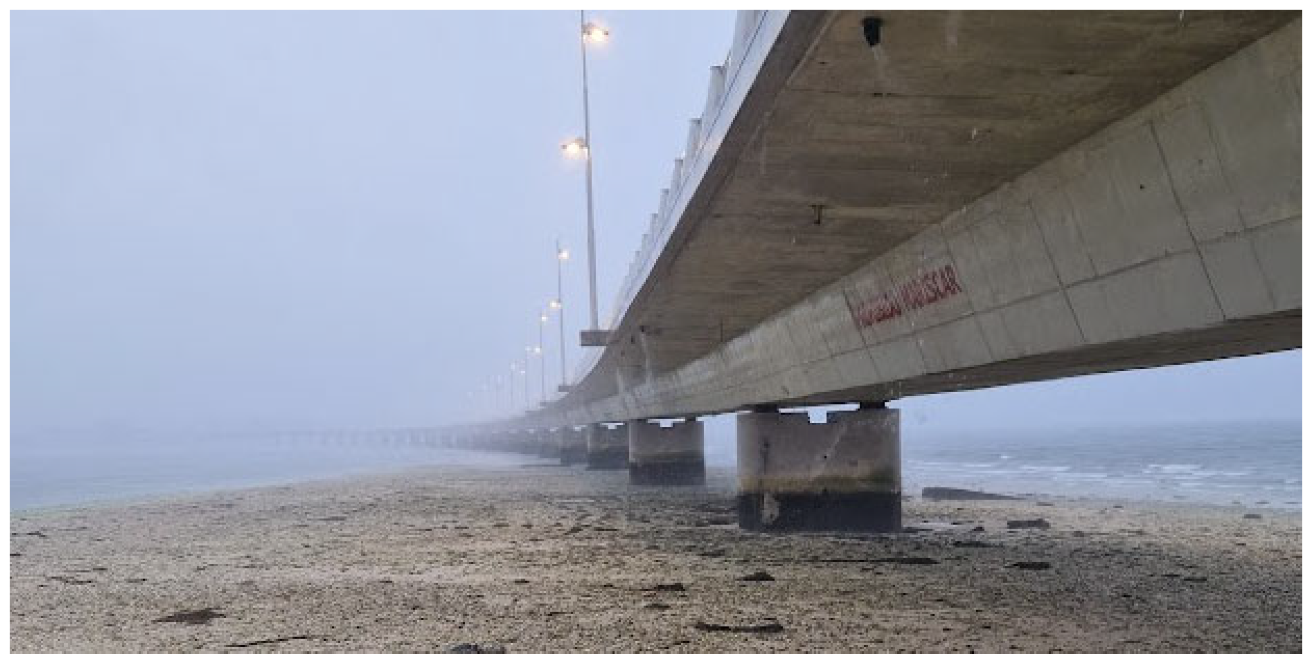
2.1. Description of the Arousa Bridge

The subject of this research is a bridge that connects the island of Arousa with the coast of Galicia, located in the northwest of Spain. This reinforced concrete structure was designed and constructed in the mid-1980s and commissioned in 1985. This structure falls under the jurisdiction of Galicia’s regional government [10].

2.2. Structural Typology and Materials

The bridge has an overall length of 1980 m and is designed within a circular radius of 2.5 km. It comprises 40 spans over 39 piers. Of these spans, 38 measure 50 m, while the 2 terminal spans are 40 m each. Notably, expansion joints are present only at the abutments.
The deck features a single box girder, with a height of 2.30 m, incorporating two transverse projections. The total width of the roadway is 13.00 m, allocated as follows: two sidewalks of 1.50 m each, two shoulders of 1.50 m, and two traffic lanes of 3.50 m [11].
The deck was cast in situ using the mobile scaffolding system technique with a typical construction cycle of one span per week, casting on Fridays and prestressing on Sunday-Monday. The standard concrete mix included 485 kg/m3 of Portland cement without additions.
Prestressing strands were composed of wires made of specially stabilized steel with a guaranteed minimum ultimate strength of 1860 MPa kg/cm2 and a relaxation ratio of less than 3% under 1300 MPa tension applied for 1000 h.
For the construction of the piers and abutments, reinforced concrete was employed. In addition, the piles and abutments utilized a cement mix with added pozzolan, maintaining a total dosage of 332 kg/m3 of concrete (full details in [11]). The original cover depth was only 30 mm; during the repairs, the value was increased to 40 mm [11,12].

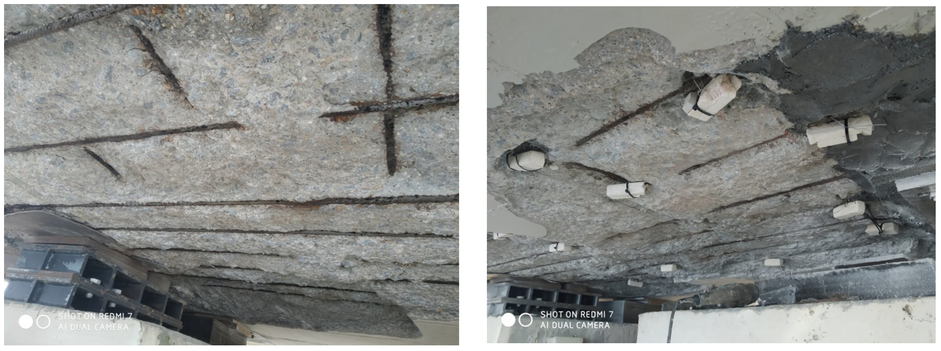
2.3. Summary of 2007 Inspection: Observations and Intervention Program

The bridge underwent a comprehensive inspection in 2007, which led to the conclusion that a full intervention was necessary. The identified pathologies included (1) corrosion damage in the deck and piers; (2) shear cracks and compatibility issues within the deck; (3) the presence of gravel nests in the piers and abutments; (4) corrosion of the bearing plates; (5) deterioration due to inadequate surface drainage; (6) degradation of neoprene pot bearings; and (7) damage to lighting fixtures.
The overall structural condition of the bridge was assessed as satisfactory; however, certain salient durability issues which were to be expected given the time elapsed since construction and the harshness of the marine environment were noted. This environment, characterized by a high saturation of chloride ions (Cl), has caused localized corrosion of the reinforcement in specific areas; mainly focused in the tidal and splash zones. While this corrosion did not compromise the structural integrity, significant visible damage affects the aesthetic appearance of the bridge.
In concrete rehabilitation, the traditional approach is to implement localized repairs. This technique was executed with satisfactory results in pier 1, selected for this treatment due to ease of access from the island abutment, which served as reference for the ulterior analysis of the evolution of the repair. Nevertheless, due to the aggressive nature of the environment, a decision was made to also employ cathodic protection methods alongside the localized patch repairs to enhance long-term durability. The property decided to use two different technologies. On some of the piers, it was decided to use Fosroc technology. This system is based on a fiberglass jacket that is wrapped around the pier and includes within its inner face the sacrificial zinc and the titanium mesh; once the jacket is in position, the gap is filled with self-compacting repair mortar. This solution was installed in piers 18 to 25. However, due to the elongated shape of the piers (Figure 1), the application of the system proved to be challenging to the point that proper working order was never achieved. Taking stock of the situation, it was then decided to use DuoGuard CPT discrete anodes—which were already being installed in some sections of the deck—in the rest of the piers, namely 2 to 17 and 26 to 38.

2.4. Design and Implementation of the DuoGuard CPT System

The density of application of anodes is calculated from the density of the steel reinforcement following the supplier recommendation. The objective of the anode installation is to protect selected areas of the reinforcing steel in the piers of the bridge. A description of the procedure to calculate the density of steel reinforcement and thus the density of anode units can be calculated as follows for the piers:
It is assumed that the protected area on the piers is 1.5 m above high tide down to variable levels dependent on the size of the individual pier.
The reinforced concrete in the region of high tide is considered to be atmospherically exposed; i.e., sufficient oxygen diffusion to the steel occurs in order to facilitate significant corrosion activity. This region would be treated with DuoGuard at the recommended spacing. This is identified as Zone 1 and spans a full length of 1.5 m.
Reinforced concrete in the region below high tide is assumed to increasingly have significantly reduced oxygen access and higher chloride content diffused into the concrete matrix, compared with the high-tide zone (Zone 1), due to being submerged in saltwater for an appreciable proportion of time. The level of corrosion activity in this area is likely to be relatively lower compared with the high-tide area. Polarization of the steel is relatively easier in this area due to the lower concentration of oxygen present. This, and the increased conductivity of the concrete, allows the spacing of the DuoGuard units to be increased. This is identified as Zone 2 which comprises from 1 m below high tide to just below mid tide, for a full length of 2.2 m.
Below mid tide, reinforced concrete is substantially immersed in sea water. Oxygen ingress into concrete and thus to the reinforcing steel is limited by the presence of high moisture levels, and thus, the likelihood of aerobic corrosion is lower. In addition, the concrete conductivity is higher due to chloride salt saturation. Consequently, a decision was made to further reduce the DuoGuard density in this area, identified as Zone 3 and defined from just below mid tide to below low tide, for a full length of 3.5 m.
The steel surface density of the column is assumed to be the same throughout and is calculated as follows:
(1)
Vertical steel surface: 12 mm rebar diameter, at 250 mm spacing 4 bars/m × 0.012 m × 3.14 × 1 m = 0.15 m2.
(2)
Horizontal steel surface: 10 mm rebar diameter, at 200 mm spacing 5 bars/m × 0.010 m × 3.14 × 1 m = 0.16 m2.
The total steel surface is 0.31 m2 steel surface/m2 concrete surface, which, notably, is a low value in comparison with other infrastructures. Taking into account that the perimeter of a pier is approximately 12.4 m, the following anode distributions, split into three areas and designed to fit reinforcement spacing (Figure 2), ensue:
(1)
Zone 1—500 mm × 400 mm mesh over a surface area of 31 m2, resulting in approximately 150 units per pier, in six rows.
(2)
Zone 2—500 mm × 600 mm mesh over 27.2 m2, resulting in approximately 100 units per pier, in four rows.
(3)
Zone 3—800 mm × 600 mm mesh over 43.4 m2, resulting in approximately 80 units per pier.
Figure 2. Corrosion protection of the piers: disposition of discrete anodes in zones 1, 2, and 3.
Infrastructures 10 00141 g002
The zone below low tide is oxygen-starved and is influenced by the sacrificial anodes positioned in the concrete above; it is therefore suggested that additional DuoGuard anodes may not presently be required in this area.
On application, the conductive titanium wire connecting all the DuoGuard anode units on each pier should be run into a water-tight connection box along with the steel connections—this allows re-access to the system at any future date if further current delivery is required.
As a monitoring complement to the corrosion protection system, MnO reference electrodes were installed in piers 1, 4, 9, 14, 18, and 37. These piers were the structural elements with most corrosion damage; therefore, it was decided that they would be the monitoring target. Connection boxes for ease of readout were installed inside the main girder.
Protection criteria were set according to ISO 12696:2022 standard, Section 8.6 [13]. When any of the following conditions are met, the structure is considered adequately protected against corrosion:
(1)
An instant off potential more negative than −720 mV with respect to Ag/AgCl/0.5 M KCl.
(2)
A potential decay over 2 h and up to 24 h of at least 100 mV from “Instantaneous OFF”.
(3)
A potential decay over a 24 h period or longer of at least 150 mV from the instant off.
Corrosion risk through potentials
As the initial status report indicates high chloride contents, short periods of impressed current were applied in the first weeks after the repair. Once sufficient alkalinization and chloride migration was attained, the external current was stopped, and the system was connected in passive configuration. Thus, the galvanic difference of steel and zinc was responsible for protection. León et al. [12,14] published in detail the initial repair works and Becerra-Mosquera et al. [10,15,16] the following supervision of the cathodic protection functioning.

2.5. Inspection of 2021

In 2021, a routine visual inspection of the bridge revealed several anomalies that warranted further investigation (Figure 3). Notably, significant displacement was observed in the bearings of pier No. 38, alongside indications of localized corrosion damage in the abutment. Those parts were not repaired in the 2011 intervention. These observations raised concerns regarding the structural integrity and performance of the bridge, prompting the need for a more thorough examination of its overall condition.
As a consequence of these initial findings, a detailed assessment was conducted to evaluate not only the current state of the bridge but also to assess the long-term effectiveness of the repair interventions implemented over the previous decade. This comprehensive evaluation aimed to analyze the performance of the repair strategies employed, identifying potential deficiencies and areas requiring additional remedial action.
The investigation involved a multi-faceted approach, incorporating advanced diagnostic tools and methodologies to ensure a thorough analysis of the structural components. By examining factors such as material degradation, load-bearing capacity, and the overall resilience of the bridge against environmental influences, the study aimed to provide insights into the longevity and efficacy of past interventions.
Ultimately, the findings from this detailed investigation are intended to inform decision-making regarding future maintenance strategies, ensuring that the bridge continues to meet safety standards while effectively addressing the challenges posed by its operational environment. This proactive approach to structural assessment underscores the importance of regular monitoring and evaluation in maintaining the integrity of critical infrastructure.

3. Materials and Methods

3.1. Inspections and Protection Criteria

The routine inspections of Arousa Bridge are visual; inspectors complete conventional reports about evidence of damage. Every 3 to 5 years, there is a corrosion assessment of the structural health. In these inspections, some control piers are inspected in further detail using their MnO reference electrodes. In these piers, reinforcement corrosion potential against the reference electrode, the instant off, and the 2 h and 24 h decay can be measured. The initial monitoring was intense until 2014 (every single pier every 3 months) [10,15], at which point it was confirmed that the system was operating effectively. Consequently, the monitoring process was scaled down, limiting data collection to fewer piers and extending the time intervals between assessments (only piers with reference electrodes and an interval of nearly 2 years on average).
The long-term evaluation of the bridge followed a standard protocol, including frequent visual inspections to detect potential issues. These inspections were supplemented by basic measurements of electrical potentials in the repaired areas. However, rather than monitoring all system components, the protocol required sampling at least one element from each type of repair zone. For instance, in a 2017 inspection, only three piers were assessed: pier 1 (conventional repair), pier 4 (CPT technology), and pier 18 (Fosroc technology).
To assess the effectiveness of the cathodic protection systems, the UNE-EN ISO 12696:2022 standard for cathodic protection of steel in concrete was used as the primary reference [13]. This European standard establishes the necessary parameters to confirm the correct operation of cathodic protection systems. Additionally, the ASTM C876-15 standard was applied to provide additional verification regarding corrosion activity [17].
Each repaired pier contained a junction box, allowing direct measurements as specified in ISO 12696:2022. These readings provided essential data on the performance of the cathodic protection system. Furthermore, reference electrodes installed in some of the piers permitted the measurement of corrosion potential, offering statistical indicators of steel corrosion risk in accordance with ASTM C876-15.
Only some of the piers presented potential decays of 100 mV at 2 h and/or 150 mV at 24 h. Therefore, there was uncertainty about the protection of the system. To complete this, the ASTM C876-15 provides guidance for interpreting corrosion potential values [17]:
(1)
If potentials over an area are more positive than −0.20 V CSE, there is a greater than 90% probability that no reinforcing steel corrosion is occurring in that area at the time of measurement.
(2)
If potentials over an area are in the range of −0.20 to −0.35 V CSE, corrosion activity of the reinforcing steel in that area is uncertain.
(3)
If potentials over an area are more negative than −0.35 V CSE, there is a greater than 90% probability that reinforcing steel corrosion is occurring in that area at the time of measurement.

3.2. Core and Sacrificial Anode Extraction

As additional repairs were needed in 2021, it was decided to reevaluate the residual life assessment of the initial repair. For this reason, six cores were extracted from the reference, conventionally repaired pier 1, and from piers 4 and 37 with the CPT system. In each of these three piers, two positions were considered: Zone 1 (high tide and splash) and Zone 2 (tidal range), where the corrosion was more intense before the repair. Additionally, the cores were bored in the center of a set of four discrete anodes in the CPT piers 4 and 37. The goals were to determine whether the system was functioning correctly in Zone 1 and whether there would be a need, in the near future, for significant interventions on the already repaired sections.
These cores were used to evaluate chloride ingress and carbonation. The chloride was measured through three different tests. First, on a fresh surface, micro-FRX was used to map the total chloride content. Then, silver nitrate (AgNO3) was sprayed for visual detection of chloride penetration. Finally, the chloride profile was determined in the laboratory according to EN 14629 [18]. A carbonation check was performed in freshly fractured fragments of the cores using the phenolphthalein method.
Alongside the core extraction campaign, recovery of zinc sacrificial anodes to evaluate directly the consumption of zinc was planned. It was possible to recover 10 anodes in total: four from pier 4, three from pier 9, and three from pier 37.
Zinc anode consumption was measured following the recommendations of DNV-RP-B401 [19]. The recovered anodes are first mechanically cleaned of oxidation products and attached mortar. Once the surface is exposed, the anodes are immersed for 2 h in ammonium chloride (saturated). After this, the anodes are washed in water and immersed in ethanol. The result is the mass loss estimation of the anode during its cathodic protection. It is compared with the original mass of the anode at installation.

4. Results and Discussion

4.1. Structural Health Assessment

Following the partial inspection of the structure in 2021, a comprehensive study was initiated to assess its service life. There were new measurements of corrosion potentials making a map all over the pier surface, extraction of concrete cores for analysis, and verification of the residual zinc content in the system.

4.1.1. Corrosion Risk and Potential Values

The evaluation criteria of the risk of corrosion that was established was the measurement of potential against the reference electrodes installed during 2011 repair. In Figure 4, it can be seen that in the last assessment in 2022—after some specific repairs in the continental abutment—the potential values are shifting towards the risk of corrosion according to ASTM C876. This is a criterion taken into consideration only as reference, as ASTM C876 does not apply under CP.
One thing that also arose was that these values offer a limited view of the corrosion status, as they are missing important data. They can serve as indicator but should not serve as the unique evaluation method [20]. For instance, the potential in pier 1—which was repaired with conventional patch repairs—was consistently measured as presenting values indicating reduced risk; however, as can be seen in Figure 5, it presented visual indications of the initiation of corrosion. The hypothesis for this disagreement is that the reference electrode was installed in a large, repaired patch, and this corrosion was happening in less repaired areas. So, the values measured against this reference electrode might be reflecting a more favorable situation than they would in a thorough characterization. The new measurements of corrosion potentials show that the system is not working properly.

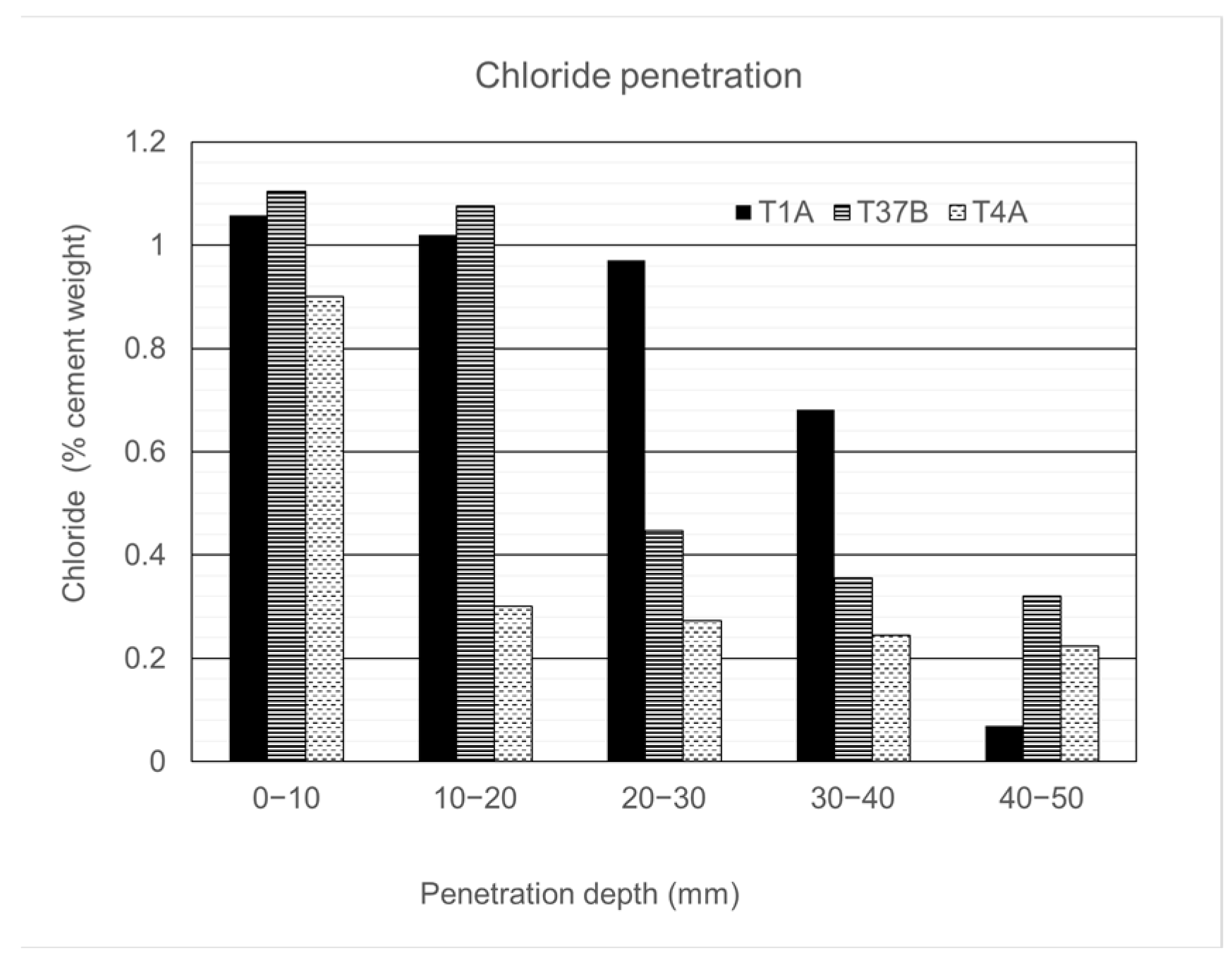
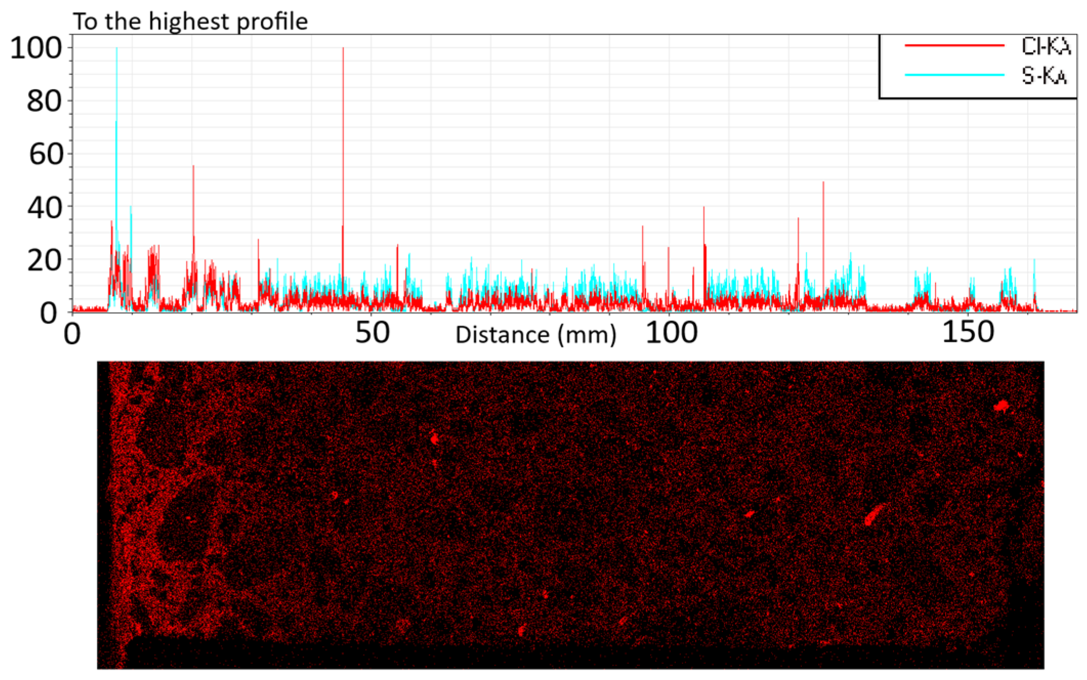
4.1.2. Chloride Penetration and Carbonation

In order to evaluate chloride penetration, six cores were extracted from repaired areas from the piers 1, 4, and 37. The samples from each pier were named A and B; A were obtained in the splash zone and B in the submerged zone. Each core was tested for its chloride profile up to a depth of 40 mm (Figure 6).
Prior to the repair, chloride content ranged between 1.05% and 1.35% by weight of cement. Following the repair, chloride levels in the exterior part recovered to saturation point. It is important to remark that pier 1, with conventional repair, exhibited very high chloride concentrations after the repair, opening the way to restart corrosion propagation in the short term.
The lowest chloride concentration which initiates corrosion was estimated for the initial intervention to be 0.6% Cl by the mass of cement using the EHE reference [21]. Based on different results, it was suggested that the chloride threshold level was lower than 1% Cl by the mass of cement for samples exposed to static moisture conditions, and lower chloride concentration can initiate corrosion in dynamic moisture conditions. Under severe environmental exposures or dynamic moisture conditions, reported values as low as 0.2% to 0.4% emerge [22]. There is significant variability in the literature about the chloride threshold, with an average value of 0.68 (% Cl/weight of cement) with a standard deviation of 0.47 [23].
Bertolini et al. [23] state that cathodic protection offers a significant increase in the chloride threshold to initiate the corrosion and refers to levels of 0.7% with respect to cement mass. If the cathodic protection reaches high current densities, values up to 3% can be tolerated without corrosion (this level is only possible with impressed current).
Chloride content is high near the surface, and in pier 1, it seems that it reaches the reinforcement; in piers 4 and 37, the initiation levels reach 20 mm in depth, and the corrosive effect of the chloride is not yet activated. The pit re-alkalinization applied at the beginning of the repair seems to have been effective.
The penetration of chloride by silver nitrate was inconclusive and—from the authors’ perspective—it is not recommended in this case and might not be useful in repaired elements (Table 1). Similar conclusions could be indicated with the microFRX (Figure 7, Figure 8 and Figure 9); this semiquantitative technique at least indicates a homogeneous front of chloride penetration; however, it does not provide conclusive results in terms of the depth of the penetration of the chloride. Another aspect that it reveals is the presence of trace amounts of chloride at all depths, meaning that the chloride is present in all the concrete profile—however, not at initiation levels.
The carbonation of the samples was measured with the phenolphthalein method in freshly broken fragments; in all core samples, the results indicated a carbonation depth between 8 and 12 mm. The risk of carbonation corrosion is therefore still low in the piers.

4.1.3. Anode Consumption

As part of the evaluation, it was possible to recover 10 anodes from piers 4, 9, and 37. Figure 10 shows the recovered anodes alongside one of the original anodes that was preserved for comparison. Table 2 reports the remaining zinc mass percentage.
As the results are very similar in the different piers, it is important to assess the uncertainty of the measured anodes. In this case, the mean value of all the recovered sacrificial anodes would be 84.9% of remaining zinc. This is consistent with the annual consumption published by Sergi [5] and when taking into account the dispersion of the total of 10 recovered anodes.

4.2. Repassivation of the Galvanic System

As signs of corrosion were detected, it was decided to assess whether it was convenient to perform the repassivation operation in the system, consisting of connecting impressed current for a short period, namely, 1 week [24].
To that end, a test was performed on piers 4 and 37. The potential was measured in a grid of points with an external MnO reference electrode. These values were divided into zones 1, 2, and 3 (respectively, high-tide and splash, medium tide, and mostly submerged). The results are provided in Figure 11.
Corrosion potential values measured in pier 1 (which has no cathodic protection) indicate a high risk of corrosion, corresponding to high risk with potential values more negative than −350 mV (ASTM C876-15 reference). Even piers 4 and 37 in the most attacked zone present a risk of corrosion at heights exceeding 3 m above sea level. After the application of 12 V for 1 week of impressed current to the system (with the use of a power supply and measuring the daily register according to the suppliers’ specification [25]), the parameters shifted towards positivity, indicating the effectiveness of the repassivation and activation of the sacrificial anodes. This enhancement indicates that the application of impressed current positively affected the system, promoting a higher level of protection for the structure.
In piers 4 and 37, corrosion potential values improved throughout the entire pier height, with notable enhancement in the splashing area.
After the application of impressed current, the current intensity values within the system significantly decreased for both pier 4 and pier 37. Specifically, measurements in pier 4 reduced from 40 mA to 8 mA, while those in pier 37 decreased from 13 mA to 3 mA. These reductions indicate a lower galvanic current requirement by the system following the application of impressed current, suggesting that the impressed current has effectively repassivated the system [2].
Because of this analysis, the elaboration of intensity (measured at the system’s junction box) vs. time curves has been set as a new goal in the monitoring procedure. These could facilitate the evaluation of the necessity of impressed current applications during routine inspections of the system’s junction boxes.

4.3. Residual Life Estimation of the GCP System

4.3.1. Initial Calculation

The charge capacity of a single anode can be calculated from the charge capacity of 760 Ah/kg and using the following calculation to take into account practical usage factors:
  • Available charge = charge capacity (Ah) × efficiency (85%) × utilization (85%), according to supplier specification [25].
With an anode weight of 200 g, this provides a charge capacity of 110 Ah for a single anode. Since each anode is assumed to consume 5% of the anode mass in delivering the impressed current in the first week, this provides an available charge capacity of 110 Ah × 0.95 = 104 Ah. The charge capacity of each of the three zones on each pier is provided in Table 3.
The lifetime of the anodes can then be calculated as follows:
  • Lifetime = available charge capacity (mAh)/current output (mA)
The typical current output of the anode system was reported by Byrne et al. [1]. Those data, taken from site installations, indicate a service life between 50 and 340 years dependent on the local conditions in which the concrete structure is situated. The most aggressive anode consumption rates reported, 0.11 mA current delivery per anode, are assumed in these calculations, and an additional engineering safety factor of 2 is incorporated to allow for increased temperatures anticipated in Spain versus the UK (reference for this manufacturer). This provides current outputs per m2 of steel surface and lifetime estimated as shown in Table 4.

4.3.2. Residual Life of the Repaired Bridge

At this stage, the evaluation of the remaining zinc in the cathodic protection system has been conducted based on the assumption that each anode consumes 5% of the anode mass in delivering the impressed current in the first week. Daily measurements of the current carried out during this first week of impressed current provided evidence that this assumption is correct.
Electrical charge assessments were performed in accordance with the current intensities measured during each of the inspections conducted (details in Section 4.1.3). In 2024, the anodes presented a remaining zinc mass of 84.9%, with a 95% probability interval of [79.2%, 90.6%].
The data presented in Table 5 reveal that the consumption values derived from the current measurements are significantly higher than the average remaining zinc quantity from the anodes that were removed from the piers for testing and analysis. At first glance, this finding seems to indicate a conservative estimation of the system’s zinc consumption, thereby providing reassurance regarding the structure’s anticipated service life. Such an interpretation suggests that, from a preliminary standpoint, the cathodic protection system remains robust enough to extend the lifespan of the structure beyond initial expectations.
In light of these findings, we conclude that the estimated lifetime values, which are derived from the observed galvanic current consumption during ongoing system evaluations, fall within the anticipated orders of magnitude when compared to the zinc content of the anodes that were retrieved and subsequently analyzed. Given that the cathodic protection system was originally designed with a lifespan of 50 years, our analysis suggests that the actual operational longevity may extend to approximately 52–70 years (plus 13 years since the repairs, resulting in a real total of 65–83 years upon project decision time). This substantial increase in expected useful life highlights the effectiveness of the cathodic protection strategy employed. This is very important for decision-making in future interventions in similarly damaged structures.
These initial considerations are based on the assumptions that the aggressiveness remains constant, which can be unrealistic considering that chlorides will continue to penetrate and corrosion can reappear due to insufficient cathodic protection. Assuming a life cycle of 10 years for the reappearance of the corrosion, an additional consumption of 5% of zinc for pit re-alkalinization/repassivation every 10 years should be considered, which means 20% over 50 years. Taking this consideration into account in the calculations, our analysis suggests that the actual operational longevity may extend to approximately 40–58 years (plus 13 years since the repairs, resulting in a real total of 53–70 years upon project decision time)
Furthermore, based on our evaluations, the engineering safety factor associated with this system appears to range between 0.99 and 1.29. This implies that the system not only meets but exceeds its design specifications, providing an additional margin of safety. This additional safety margin can be applied in successive repassivations of the system. As previously observed in both piers 4 and 37, such repassivations are necessary to restore corrosion potential values to safer levels.
Such insights are crucial for future maintenance planning and resource allocation, ensuring that the integrity and performance of the structure are upheld for years to come.

5. Conclusions

The following conclusion can be drawn from this study:
(1)
The assessments conducted since the repair of Arousa Bridge in 2011 demonstrate that the applied cathodic protection systems effectively reduced corrosion risks. While some localized corrosion issues emerged in non-repaired areas, no significant deterioration was found in the protected sections.
(2)
The main indicator used to assess the corrosion risk was the potential against installed reference electrodes. This offers incomplete information, and it should be complemented with visual inspection and detailed analysis to complete the corrosion risk assessment.
(3)
There are indications that the cathodic protection system installed in the bridge could benefit from another period of impressed current to repassivate the steel and reactivate the sacrificial anode. The periodicity of this intervention was not defined previously and should be protocolized.
(4)
Reactivating the system with impressed current is likely advantageous in areas with lower humidity levels. Future research should concentrate on these regions, exploring options such as increasing the number of anodes or reducing the anode spacing, analyzing the medium’s electrical transmissivity, examining the impact of humidity on electrical transmissivity, and identifying key factors influencing system performance to recommend impressed current application for repassivation.
(5)
A more detailed investigation into the corrosion status of the bridge, including the elaboration of intensity vs. time curves (where available) is needed. Based on the measured differences in corrosion potentials at the installed control electrodes and the increased signs of corrosion, it is possible that a new shot of impressed current for re-alkalinization should be applied to the entire bridge as a preventative measure.
(6)
The cathodic protection system was originally designed with a lifespan of 50 years. Our analysis suggests that the actual operational longevity may extend to a real total since repair of 65–83 years. This increase in expected service life highlights the effectiveness of the cathodic protection strategy employed. This follow-up information is very important for decision-making in future interventions on similarly damaged structures.

Author Contributions

Conceptualization, J.A.B.-M. and D.C.-L.; methodology D.C.-L. and M.F.H.; validation, J.A.B.-M. and J.E.-L.; formal analysis, J.A.B.-M. and D.C.-L.; investigation, J.A.B.-M.; data curation, J.E.-L.; writing—original draft preparation, J.A.B.-M. and D.C.-L.; writing—review and editing, M.F.H.; visualization, J.E.-L.; supervision, D.C.-L. and M.F.H. All authors have read and agreed to the published version of the manuscript.

Funding

This research received no external funding.

Data Availability Statement

All available data are presented in the document.

Acknowledgments

We would like to thank the administration—Xunta de Galicia, Property of the Arousa Bridge, for providing access to the gathered data of Arousa Bridge, and we would especially like to thank José Enrique Pardo Landrove, head of Road Safety and Maintenance.

Conflicts of Interest

Author José Antonio Becerra-Mosquera was employed by the company Neto Structure & Heavy Lift Design. Other authors declare no conflicts of interest.

References

  1. Byrne, A.; Norton, B.; Holmes, N. State-of-the-art review of cathodic protection for reinforced concrete structures. Mag. Concr. Res. 2016, 68, 664–677. [Google Scholar] [CrossRef]
  2. Glass, G.K.; Roberts, A.C.; Davison, N. Hybrid corrosion protection of chloride-contaminated concrete. Proc. Inst. Civ. Eng. Constr. Mater. 2008, 161, 163–172. [Google Scholar] [CrossRef]
  3. Polder, R.; Pan, Y.; Courage, W.; Peelen, W. Preliminary study of life cycle cost of preventive measures and repair options for corrosion in concrete infrastructure. Heron 2016, 61, 1–13. [Google Scholar]
  4. Sergi, G. Life extension of existing steel reinforced structures by simple cathodic protection techniques for sustainable durability. In Life-Cycle of Structures and Infrastructure Systems, Proceedings of the 8th International Symposium on Life-Cycle Civil Engineering, Milan, Italy, 2–6 July 2023; CRC Press: Boca Raton, FL, USA, 2023; Volume 2023, pp. 2839–2846. [Google Scholar] [CrossRef]
  5. Sergi, G. Ten-year results of galvanic sacrificial anodes in steel reinforced concrete. Mater. Corros. 2011, 62, 98–104. [Google Scholar] [CrossRef]
  6. Stone, C.; Donadio, M.; Christodoulou, C.; Davison, N. Case studies of hybrid and galvanic systems on bridge structures. In MATEC Web of Conferences, Proceedings of the Concrete Solutions 2019—7th International Conference on Concrete Repair, Cluj-Napoca, Romania, 30 September–2 October 2019; EDP Sciences: Jules, France, 2019; Volume 289. [Google Scholar] [CrossRef]
  7. Astuti, P.; Rafdinal, R.S.; Yamamoto, D.; Andriamisaharimanana, V.; Hamada, H. Effective Use of Sacrificial Zinc Anode as a Suitable Repair Method for Severely Damaged RC Members Due to Chloride Attack. Civ. Eng. J. 2022, 8, 1535–1548. [Google Scholar] [CrossRef]
  8. Christodoulou, C.; Sharifi, A.; Das, S.; Goodier, C. Cathodic protection on the UK’s Midland Links motorway viaducts. Proc. Inst. Civ. Eng. Bridg. Eng. 2014, 167, 43–53. [Google Scholar] [CrossRef]
  9. Whitmore, D.; Sergi, G. Long-term Monitoring Provides Data Required to Predict Performance and Perform Intelligent Design of Galvanic Corrosion Control Systems for Reinforced Concrete Structures. In Proceedings of the CORROSION 2021, Virtual, 19–30 April 2021; NACE: Houston, TX, USA, 2021; pp. 1–10. [Google Scholar]
  10. Mosquera, J.A.B.; Landrove, J.E.P.; Pérez, J.M.M.; Carro-Lopez, D. Structures with chloride attack. Application of cathodic protection in the bridge to Illa de Arousa. Hormigón Acero 2017, 68, 201–207. [Google Scholar] [CrossRef]
  11. Pérez-Fadón Martínez, S. Puente a la Isla de Arosa. Hormigón Acero 1985, 36, 192–217. Available online: https://www.hormigonyacero.com/index.php/ache/issue/view/197 (accessed on 1 September 2021).
  12. González, J.L.; Aguilera, F.P.; García, F.R. Proyecto de rehabilitación del puente de la isla de Arosa. Hormigón Acero 2013, 270, 75–89. [Google Scholar]
  13. ISO 12696:2022; AENOR, Protección Catódica del Acero en el Hormigón. ISO: Geneva, Switzerland, 2022.
  14. León González, J.; Prieto Aguilera, F. Rehabilitación del Puente de Acceso a la Isla de Arosa; ACHE, Ed.; V Congr. ACHE: Barcelona, Spain, 2011. [Google Scholar]
  15. Becerra-Mosquera, J.A.; Carro-López, D.; Landrove, J.E.P.; Pérez, J.M.M. Comparison data between hybrid and galvanic anode installation in the Arousa Island Bridge. In Proceedings of the 6th International Conference on Durability of Concrete Structures (ICDCS 2018), Leeds, UK, 18–20 July 2018; pp. 729–735. [Google Scholar]
  16. Becerra-Mosquera, J.A.; Carro-López, D.; Herrador, M.F. The Arousa Island bridge. Complete refurbishment and 10 years analysis description. Struct. Concr. 2024, 25, 1554–1570. [Google Scholar] [CrossRef]
  17. ASTM C876-15; Corrosion Potentials of Uncoated Reinforcing Steel in Concrete. ASTM Standard: West Conshohocken, PA, USA, 2015; Volume 14, pp. 4–5. [CrossRef]
  18. UNE-EN 14629:2007; Products and Systems for the Protection and Repair of Concrete Structures—Test Methods—Determination of Chloride Content in Hardened Concrete. CEN: Brussels, Belgium, 2007.
  19. DNV-RP-B401; Cathodic Protection Design. Det Norske Veritas: Høvik, Norway, 2005. Available online: http://www.dnv.com (accessed on 1 September 2021).
  20. Lee, D.; Jeong, J.A. Investigation of the Effective Range of Cathodic Protection for Concrete Pile Specimens Utilizing Zinc Mesh Anode. Corros. Sci. Technol. 2024, 23, 195–202. [Google Scholar] [CrossRef]
  21. AENOR, EHE-08 Regulation of Structural Concrete. Spain, 2008. Available online: https://www.fomento.gob.es/MFOM/LANG_CASTELLANO/ORGANOS_COLEGIADOS/CPH/instrucciones/EHE_es/ (accessed on 1 September 2021). (In Spanish).
  22. Ahlström, J. Corrosion of Steel in Concrete at Various Moisture and Chloride Levels, 2014. Available online: https://portal.research.lu.se/en/publications/corrosion-of-steel-in-concrete-at-various-moisture-and-chloride-l (accessed on 21 March 2025).
  23. Bertolini, L.; Bolzoni, F.; Gastaldi, M.; Pastore, T.; Pedeferri, P.; Redaelli, E. Effects of cathodic prevention on the chloride threshold for steel corrosion in concrete. Electrochim. Acta 2009, 54, 1452–1463. [Google Scholar] [CrossRef]
  24. Page, C.L.; Sergi, G. Developments in Cathodic Protection Applied to Reinforced Concrete. J. Mater. Civ. Eng. 2000, 12, 8–15. [Google Scholar] [CrossRef]
  25. Davison, N. Duoguard 500 Specification; Specification Numbre CPT523; Concrete Preservation Technologies: Nottingham, UK, 2010. [Google Scholar]
Figure 1. Arousa Bridge, Galicia, Spain. View from Arousa island.
Infrastructures 10 00141 g001
Figure 3. Repair made on the deck around pier 38 during the 2021 repair.
Infrastructures 10 00141 g003
Figure 4. Corrosion potential after 24 h off in piers 1, 4, 9, 14, 32, and 37 in the period 2010–2022 [17].
Infrastructures 10 00141 g004
Figure 5. Signs of corrosion initiation in pier 1.
Infrastructures 10 00141 g005
Figure 6. Chloride penetration profile in core samples 1A, 4A, and 37B (UNE EN 14629).
Infrastructures 10 00141 g006
Figure 7. Sample 1-B: FRX mapping of the Cl-content and detail of the semiquantitative approximation of the Cl- and S content in a profile.
Infrastructures 10 00141 g007
Figure 8. Sample 37-A: FRX mapping of the Cl-content and detail of the semiquantitative approximation of the Cl- and S content in a profile.
Infrastructures 10 00141 g008
Figure 9. Carbonation depth in sample 37A.
Infrastructures 10 00141 g009
Figure 10. Detail of the recovered anodes from pier 9 compared with an original unused anode (top).
Infrastructures 10 00141 g010
Figure 11. Corrosion potentials of pier 1, 4, and 37 before and after the application of impressed current (applied in piers 4 and 37 that have CPT anodes).
Infrastructures 10 00141 g011aInfrastructures 10 00141 g011b
Table 1. Penetration of chloride (AgNO3 reveal).
SampleDepth (mm)
1A8
1B25
4A40
4B15
37A8
37B25
Table 2. Remaining mass of zinc in the recovered sacrificial anodes.
PierRemaining Mass of Zinc (%)
485.8
984.2
3784.3
Table 3. Charge capacities.
ZoneAnode Units/m2 Concrete SurfaceAh Capacity/m2 Concrete Surface
15520
23.3340
32.1215
Table 4. Current output and lifetime.
ZoneEngineering Safety FactorAnode Current Output (mA/m2) Steel SurfaceAnode Lifetime-Years
123.454
222.254
321.554
Table 5. Current output and estimated lifetime.
PierCapacityEstimated ConsumptionEstimated Lifetime *Measured ConsumptionUpdated Lifetime *
426,510 Ah5439.57 Ah61 years3870.46 Ah56–64 years
927,500 Ah6814.82 Ah56 years4317.50 Ah52–59 years
3732,780 Ah5468.96 Ah66 years5179.24 Ah61–70 years
* Residual lifetime values.
Disclaimer/Publisher’s Note: The statements, opinions and data contained in all publications are solely those of the individual author(s) and contributor(s) and not of MDPI and/or the editor(s). MDPI and/or the editor(s) disclaim responsibility for any injury to people or property resulting from any ideas, methods, instructions or products referred to in the content.

