1. Introduction
Culverts play a crucial role in transportation drainage infrastructure, carrying waterways beneath roads and highways. However, 45% of all culverts in the United States are currently rated in fair or poor condition [
1]. This increases to 56% when focusing on corrugated metal pipe (CMP) culverts, and it reaches a concerning 69% in New England [
1]. The urgency for strategic interventions and investments in culvert maintenance and rehabilitation is underscored by the American Society of Engineer’s most recent report card giving a grade of C- to infrastructure in the United States [
2]. One of the most prominent issues for CMP culverts is deterioration of the base or invert [
3]. There is a wide range of protective systems to prevent the initiation of corrosion, including galvanization, asphalt coating, and polyethylene coating. However, rushing water and rough silt can cause severe deterioration of the invert on a culvert that is otherwise structurally sound [
3]. As such, robust rehabilitation methods for a variety of site conditions must be available to restore the capacity and functionality of culverts while minimizing cost and disruption to travelers.
There are currently several rehabilitation methods available for CMP culverts. This includes concrete invert lining, shotcrete coating, and grouted slip lining [
3,
4]. Invert lining is focused on the rehabilitation of the base of the culvert where most deterioration occurs. Typically, 3–6 in of reinforced concrete must be placed to restore the structural capacity of the culvert. The thickness is required to provide adequate cover for the rebar as well as to prevent future corrosion and maintain the integrity of the lining, with Ohio specifying a minimum of 3 in thickness for paved invert linings [
5]. This method has its drawbacks: the thickness of the concrete can change the hydraulic properties of the culvert, which not only affects sedimentation, but also wildlife passage through the waterway [
6,
7]. Slip lining is another common repair method and involves inserting a smaller diameter high-density polyethylene pipe into the culvert then injecting grout into the space in between [
8,
9]. Typically, a low-density grout is injected, but research has been conducted on multiple types of infill [
10]. The inserted pipe acts as a stay-in-place form and provides both reinforcement and corrosion resistance to the infill that acts as the main structural component. While the slip-lining method is very effective, it can significantly affect the hydraulic capacity of the culvert [
11]. Research supports the idea that this can be mitigated by the smooth surface of the slip liner, permitting higher water velocity than the corrugated surface from the CMP culvert [
12]. While the smooth surface allows for the same flow capacity, the higher water velocity can significantly affect the wildlife that travels through the culvert [
13]. A third method of rehabilitation is shotcrete coating. Shotcrete was developed around 1910 and has been used for a wide range of applications [
14], including as a protective coating for either fireproofing or corrosion resistance [
15]. Shotcrete is a sprayed, low-slump concrete that retains its shape once placed, allowing it to be sprayed on vertical and overhead surfaces. The final surface is typically rough and porous, but when applied in multiple passes and troweled it can achieve a solid, smooth mass [
16]. For a wet-mix shotcrete, a flowable concrete is first mixed, then poured into a pump where it is transferred to the sprayer [
17]. The process of spraying typically reduces the moisture of the concrete as it exits into the air. This process helps the shotcrete stay in place on the substrate and prevents it from flowing down. This is critical for culvert lining with shotcrete to ensure a consistent layer around the perimeter is achieved [
18].
One promising method of culvert repair is the use of ultra-high performance concrete (UHPC) shotcrete for culvert lining, which was first tested in France in 2017 [
19]. UHPC, with its high strength and durability, holds promise for achieving thinner linings, thereby mitigating the hydraulic and ecological drawbacks of conventional methods. UHPC is a cementitious composite material characterized by its dense aggregate matrix, a water-to-cement ratio below 0.25, and the inclusion of internal fiber reinforcement [
20,
21]. Compared to traditional concrete, UHPC has a compressive strength exceeding 17,500 psi and a post-cracking tensile strength greater than 750 psi [
22]. The post-cracking tensile strength is largely due to the integration of small-diameter steel fibers within the mix [
23,
24] which reduce the need for conventional rebar reinforcement. UHPC also boasts exceptional durability, as its dense microstructure and low permeability significantly enhance its resistance to environmental degradation, including freeze–thaw cycles, chemical attacks, and abrasion [
25,
26,
27,
28], and allow for thinner casts since additional cover for rebar is not required. These attributes position UHPC as an ideal material for infrastructure subjected to harsh conditions and promises an extended service life with minimal maintenance. While one large-scale pilot testing of UHPC shotcrete application has been completed in France [
19], and ongoing research at Florida International University focuses on UHPC mix development for pneumatically applied UHPC for culvert strengthening [
29], this approach does not have an extensive track record for use in other applications.
This research project focuses on a proof-of-concept investigation of ultra-high performance concrete (UHPC) invert linings for the repair of deteriorating CMP culverts. The project is inspired by an ellipsoid CMP culvert in Connecticut that has reached an advanced level of deterioration.
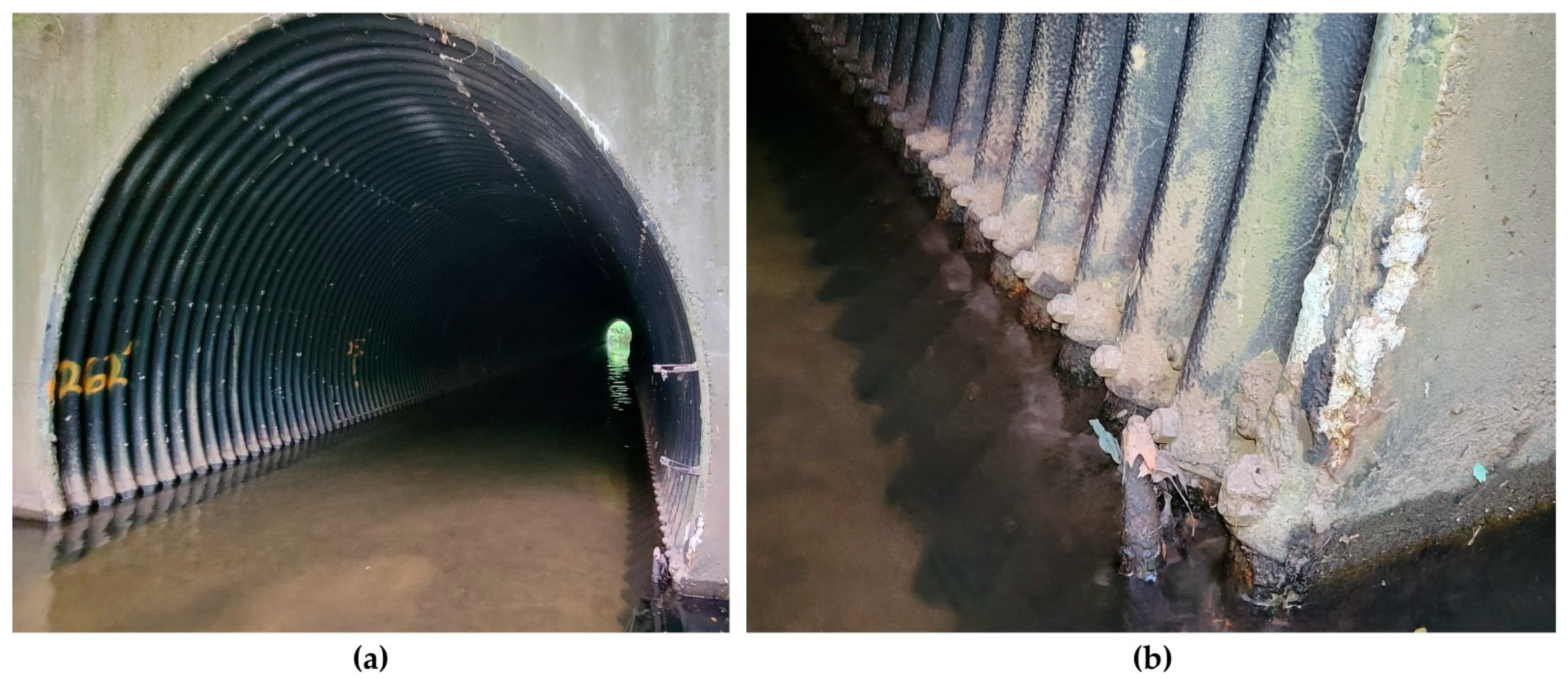
Figure 1a shows a deteriorated, in-service culvert, and
Figure 1b shows a close up of deterioration and sediment built up along the waterline. Due to the centralized deterioration at only the base of the culvert, an invert lining has been proposed for rehabilitation. The Connecticut Department of Transportation (CTDOT) and project designers proposed a 2-inch thick UHPC invert lining to restore the structural capacity of the culvert and provide a long lasting, durable protective coating.
Bridge No. 06537, a CMP culvert in Wallingford, CT, was selected for the pilot implementation of a UHPC invert lining and was the basis of the experimental study presented in this paper. It was constructed in 1965 and lies underneath the Warton Brook connector, which connects CT Route 5 and Interstate 91, and carries an average daily traffic of 15,300 vehicles per day [
30]. The culvert is an ellipsoid that is 15 feet tall, 13 feet wide (
Figure 2a), and 262 feet long (
Figure 2b). It is constructed from seven-gauge galvanized steel with corrugations that have a six-inch pitch and a peak-to-valley depth of two inches. The 2022 inspection report categorized this bridge as structurally deficient due to the level of deterioration present on the structure [
30], with an overall structural evaluation appraisal of four. Approximately 40% of the asphaltic coating has undergone erosion along the entire length of the culvert, concentrated at the bottom of the culvert at and below the waterline. Inspection of the steel surface at the waterline reveals heavy laminar rust, measuring up to 28 inches in vertical rise from the base, accompanied by section loss along the entire length of the culvert at the waterline. Moreover, examination below the water surface reveals localized perforations in the steel near the culvert floor, ranging from 0.375-inch diameter perforations to approximately 1 inch by 4 inch perforations.
Figure 2a shows the extent of the corrosion, both thinning due to laminar rust and perforations, aggregated along the length of the culvert.
During the hydrology study for Bridge No. 06537, the natural conditions that would be present if there was no existing culvert were studied as a baseline for any proposed construction. The 2000 CTDOT Drainage Manual is utilized as the governing document for water handling structures in Connecticut [
31]. Bridge No. 06537 carrying the Wharton Brook is classified as an intermediate structure, meaning it provides waterway for the drainage of areas between one square mile and ten square miles. The Drainage Manual Section 9.3.5 recommends that the proposed 100-year design discharge water surface elevation (WSE) should not be more than one foot over what is achieved in the natural conditions’ scenario [
31]. The current deteriorated culvert did not meet this requirement and exhibits a WSE of 6.4 feet above the natural profile in the 100-year design discharge scenario. It was thus deemed impractical to satisfy this criterion within the scope of the rehabilitation project, as this would require a full replacement of the culvert or multiple parallel conduits. However, it was preferred that the rehabilitation did not raise the 100-year design discharge WSE above the current conditions.
Two options were initially proposed for the design of the rehabilitation. The first option was a 4-inch-thick fiber reinforced concrete invert lining, with baffles included to mitigate an increase in flow velocities caused by the smoother surface and reduced diameter. The second option was a 12.5 ft diameter CMP slip lining, with a similar surface roughness as the existing culvert. Since both options would not only reduce the pipe’s inside diameter but also raise the effective invert elevation, the CMP slip lining option was immediately removed from consideration as it would equate to a nearly 15 inch constriction on the culvert’s flow area compared to the concrete invert lining and further affect 100- and 500-year flood discharge capacity. The second option was thoroughly investigated and showed significant promise initially.
The next main limitation was the passage of fish through the culvert. At least nine different fish species have been observed to pass through the culvert, with several using it as a migratory passage. As such, it was critical that the 2-way fish passage be maintained. This could be done by either limiting the water velocity or adding a resting area at a midpoint in the culvert. As the creation of a resting area was beyond the scope of the project, the designers focused on limiting the velocity of water through the culvert. The proposed 4-inch concrete invert lining would restrict flow and increase the velocity, decreasing the percentage of fish passing from over 87% to below 50% during the spring season. Designers countered this by proposing baffles on the top surface of the concrete invert lining. This design choice did effectively reduce the velocity of water and allow for fish migration but had the adverse effect of increasing the 100-year WSE by 0.7 ft. A final modification was proposed by adding a secondary conduit of a 60-inch reinforced concrete pipe culvert parallel to the main culvert. Unfortunately, this design choice was determined to increase the project cost approximately three times the initial budget and would not be economically feasible.
After significant discussion and investigation of alternatives, a 2-inch UHPC invert lining with no baffles was proposed. This option only slightly reduces the area of flow, with the constriction counteracted by the smooth surface of the lining to allow a very similar water output. It would reduce the 100-year WSE from the existing 6.4 feet above natural conditions to only 6.3 feet above natural conditions. While this is still above the recommended maximum elevation, it was deemed permissible within the scope of a rehabilitation project to maintain the same or better conditions than the existing structure. Additionally, while spring season fish passage would reduce to approximately 70%, this was deemed acceptable as it was for a limited time and would allow over 95% passage during yearly average conditions. UHPC was chosen over standard concrete as it allows for much greater durability and strength even at reduced thickness. Without the need for structural rebar and corresponding clear cover, UHPC is ideal for a much thinner cast. The increased durability and water impenetrability posits UHPC as an ideal material for marine applications such as culvert linings.
Although there have been two documented attempts at culvert rehabilitation with UHPC, both lack practical depth for immediate implementation, and both focus only on spray-applied UHPC shotcrete. Huynh et al. describes the first mockup implementation in the literature and focuses on the mix properties of the UHPC, with some discussion of the need for new culvert rehabilitation methods and benefits of UHPC [
19]. Afzal et al. describes a comprehensive project for developing a UHPC shotcrete, with culvert rehabilitation listed as its main use case [
29]. The researchers in that study extensively developed a mix design for pneumatic spraying, as well as equipment specifically for UHPC spraying. However, its narrow focus on shotcrete UHPC and non-proprietary UHPC make it less relevant in many states that exclusively use proprietary mix designs. This limitation is due to the variability of UHPC and necessity for on-site modifications depending on temperature, placement method, and mixing equipment. These papers show a significant research gap in the practical implementation of a UHPC invert lining, as well as real-world construction challenges that can occur outside of the tightly controlled research environment. For owners and designers hoping to implement a UHPC invert lining in the field, there is a need for hands-on tests and mockups to show the practical limitations, challenges, and design constraints. Additionally, there is a lack of documented projects showing conventional UHPC with formwork being used for culvert rehabilitation and thixotropic UHPC being used outside of bridge deck overlays [
32,
33]. As overlays typically have a low grade requirement, the viscosity for a nearly vertical surface of an invert lining is significantly higher.
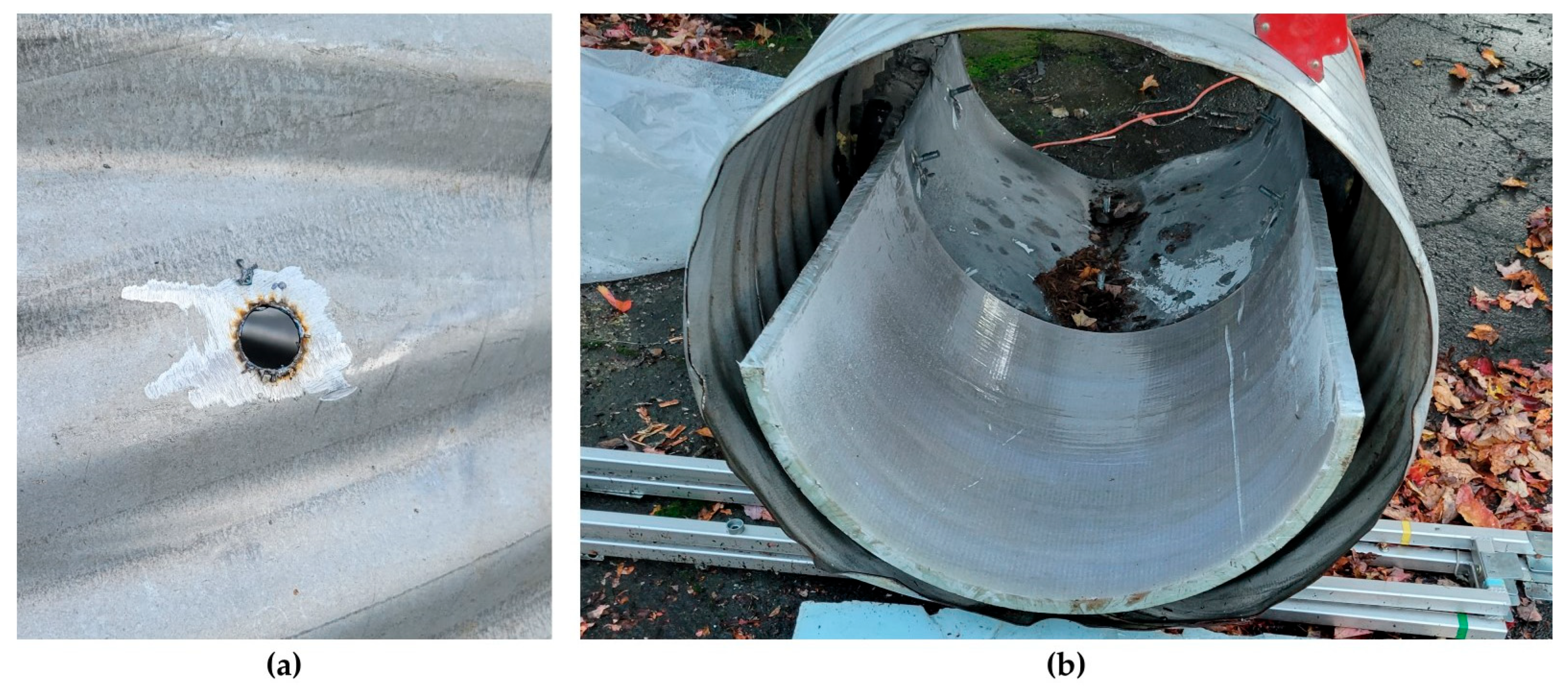
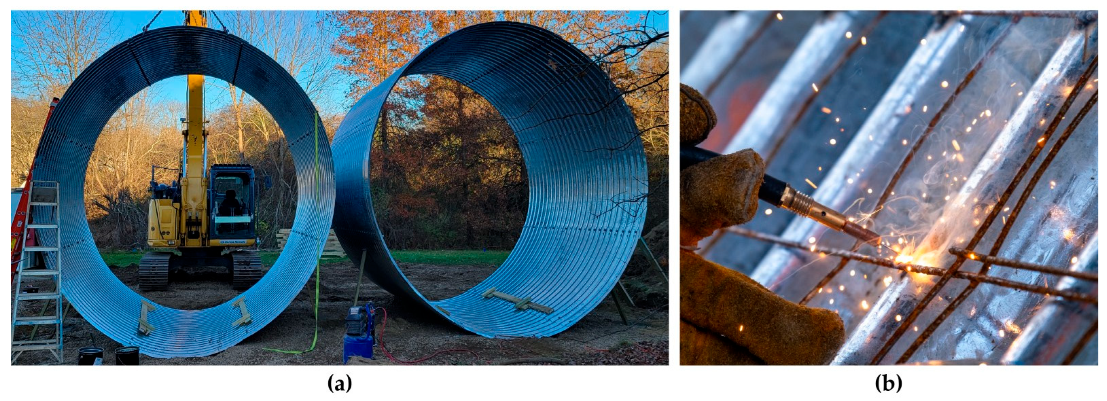
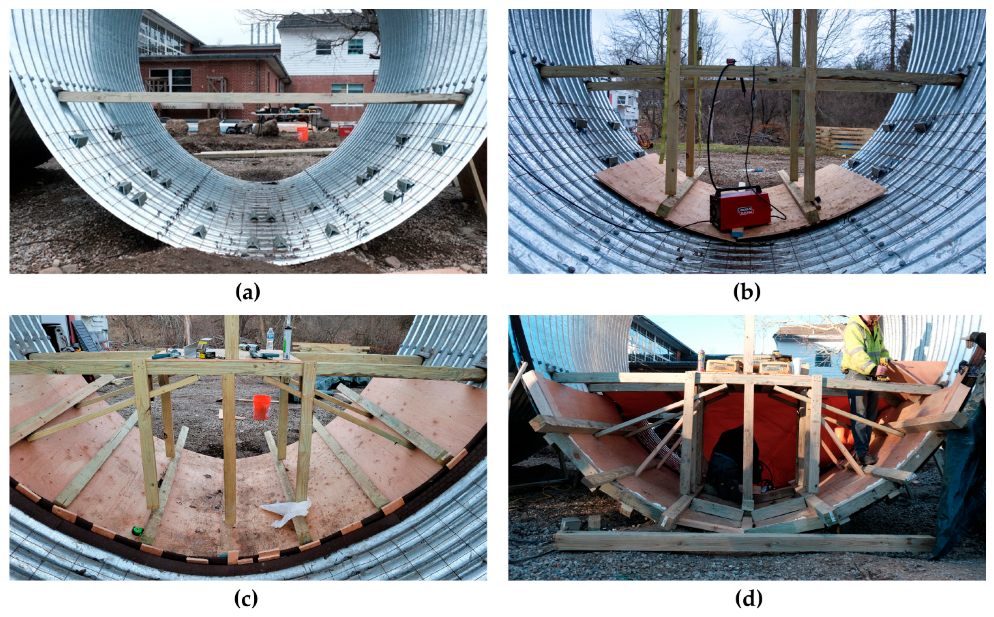
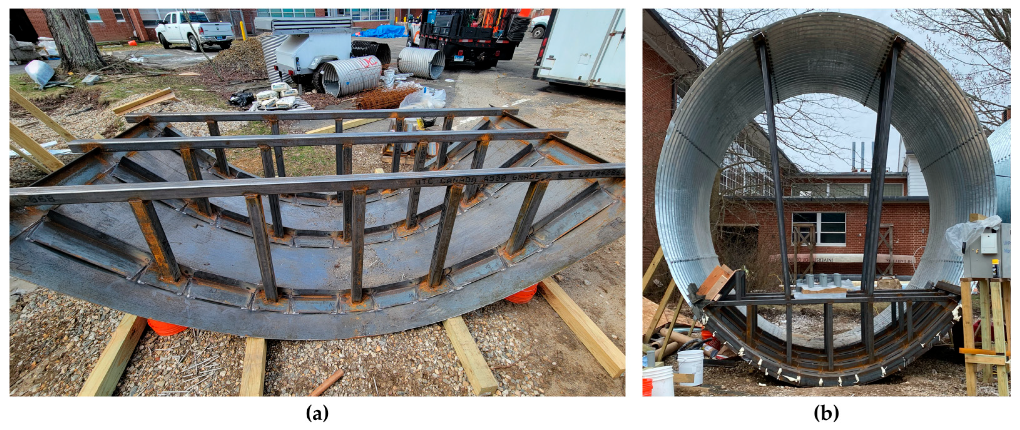
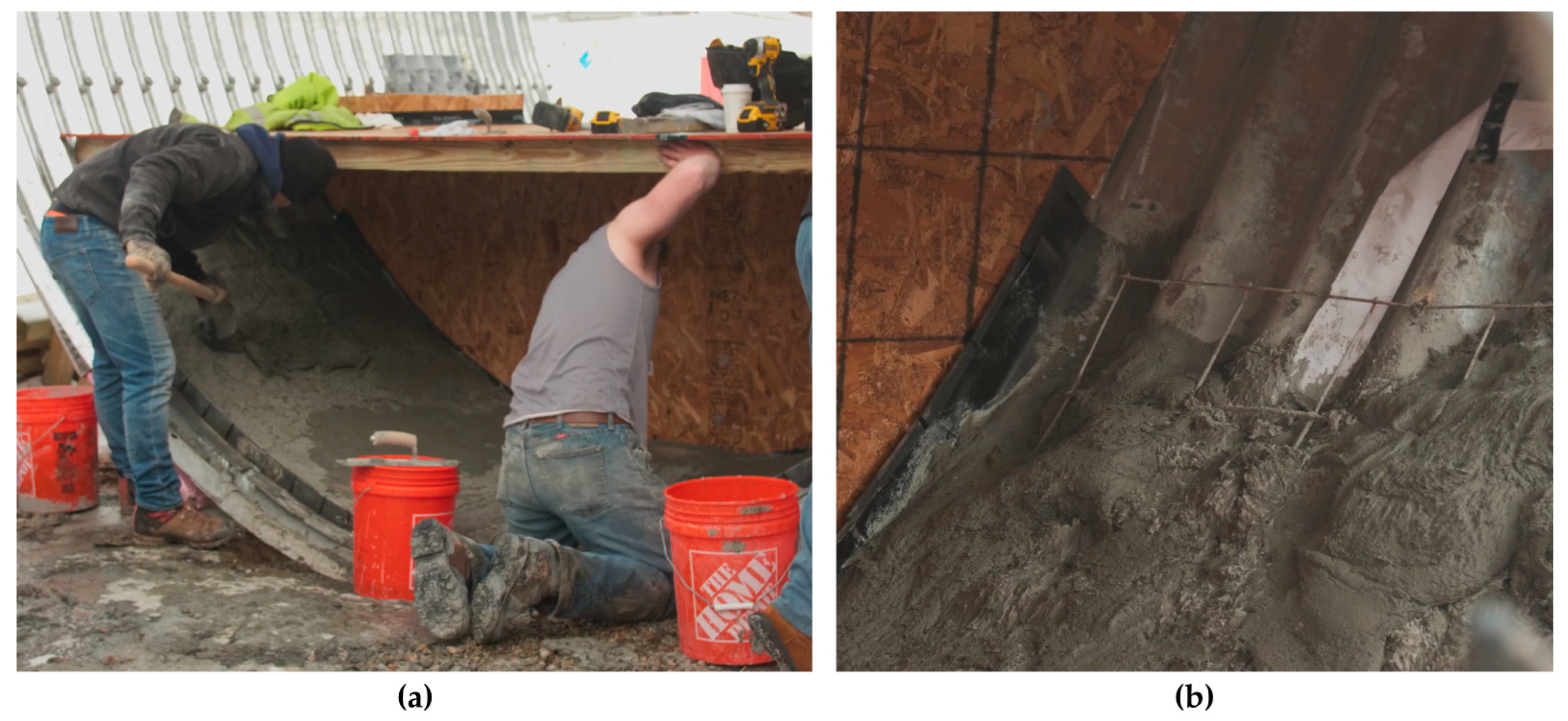
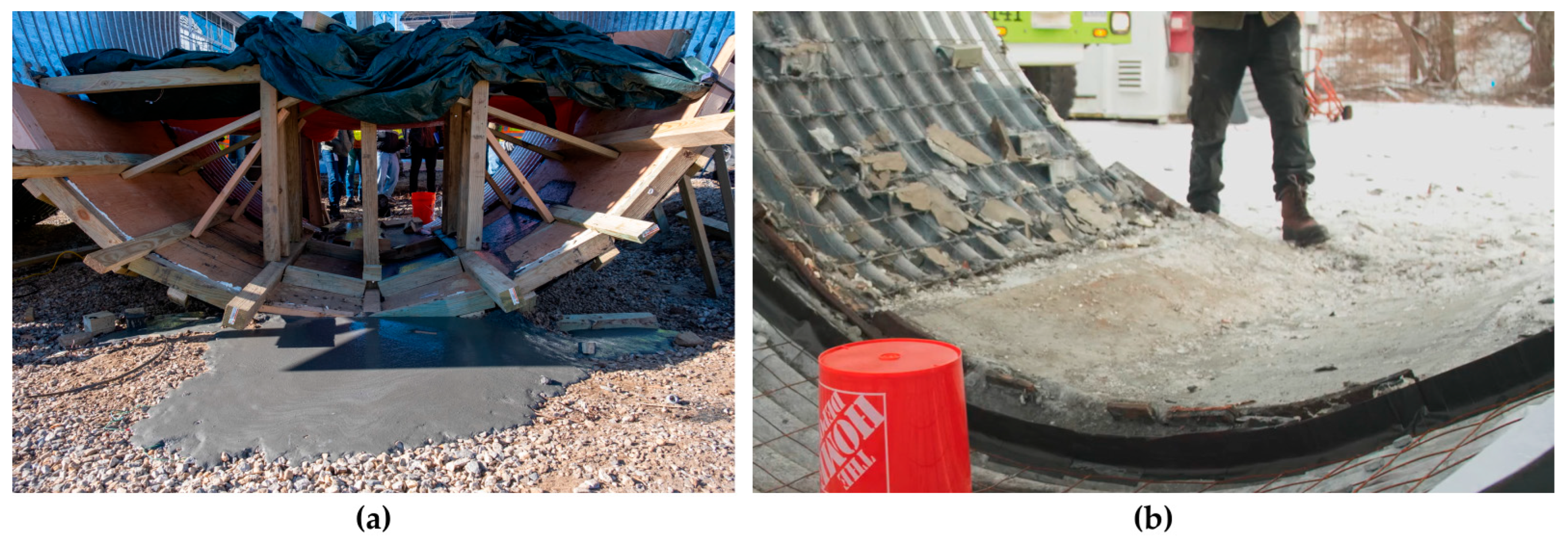
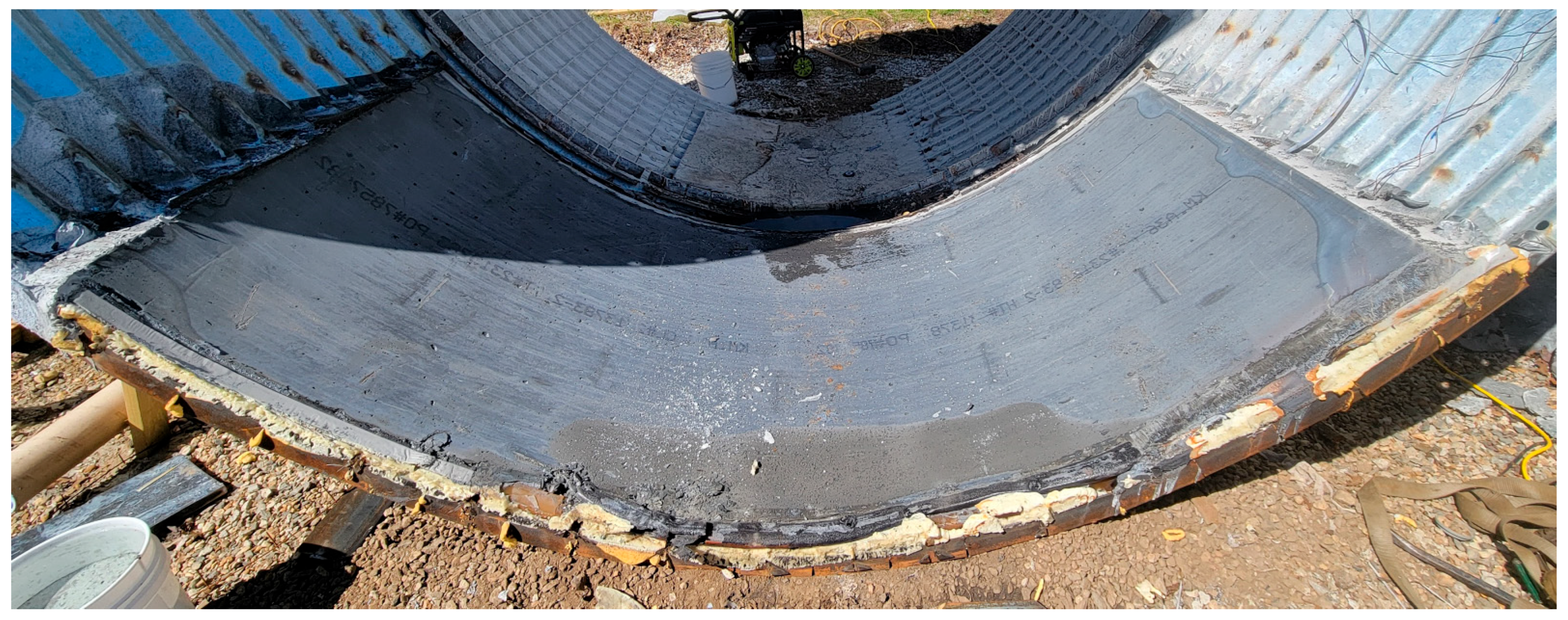
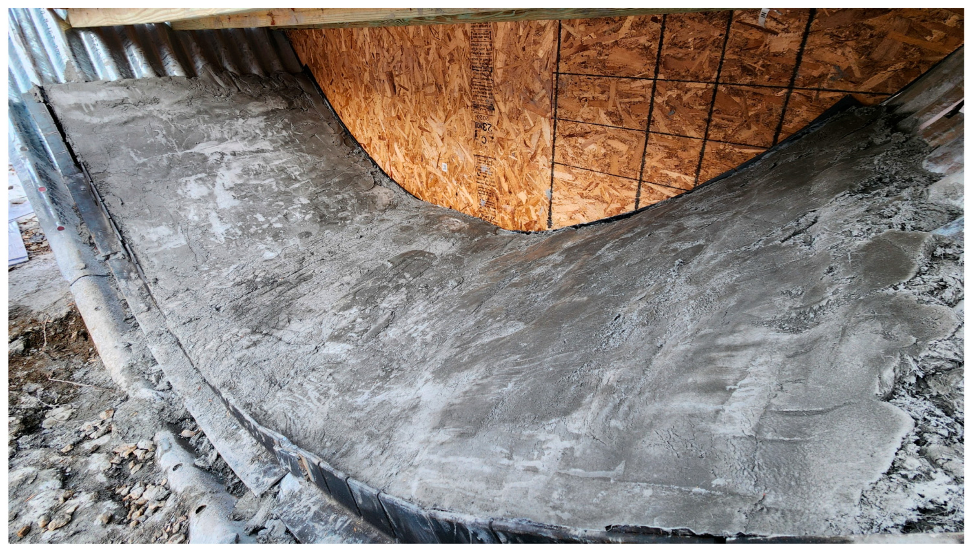
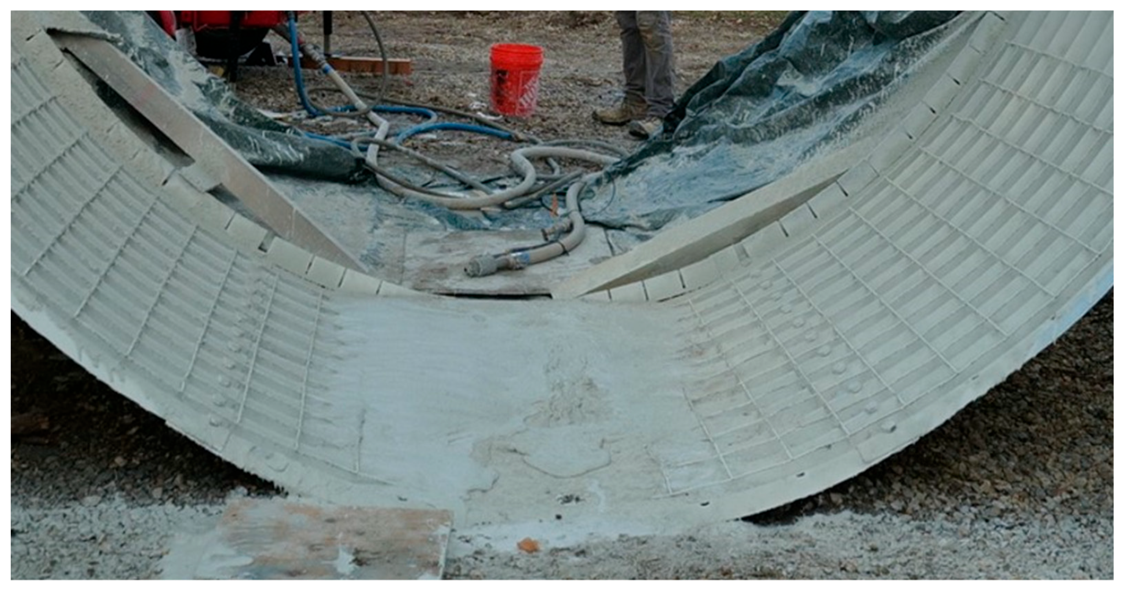
Researchers at CTDOT and the University of Connecticut have performed several mockups for the investigation of a UHPC invert lining for the rehabilitation of large CMP culverts. The first phase of the project is a proof-of-concept investigation focused on trial placements at UConn’s Depot Campus, where large scale culverts were fabricated for testing. Three small-scale mock-ups were performed on 30-inch diameter culverts, and four large-scale mockups were performed on fabricated culverts of similar circumferential dimensions to the Wallingford culvert. The small-scale mockups investigated basic properties of galvanized steel culverts, including weldability to the surface, challenges with curved formwork, and casting methods. The large-scale mockups addressed constructability constraints and evaluated three different forming and casting approaches including traditional UHPC mixes with top forming and two methods that did not require top forming, a thixotropic UHPC and shotcrete UHPC.
Table 1 summarizes the seven total mockups, showing the differences in size, UHPC mixture type, formwork type, bulkhead, and formwork standoffs when applicable. Five of the mockups used a standard, self-leveling UHPC with formwork to develop the curved shape and required thickness, while two used experimental UHPC consistencies for formless placement. This paper documents all the mockups conducted for this project, with lessons learned from each trial. Ultimately, this project identified two feasible placement methods for UHPC invert linings: a conventional UHPC mixture with engineered steel formwork and thixotropic UHPC with no formwork. Conventional UHPC with top forming was found to have the highest quality invert lining, with a smooth, consistent finish, at the cost of increased time and complexity for both the formwork design and fabrication. Thixotropic UHPC with no top forming also successfully achieved 2-inch thickness with reduced fabrication time, at the cost of a less smooth and consistent finish.
While the goal of this project was to support a specific implementation of culvert rehabilitation in Wallingford, CT, it is the author’s intent to provide actionable lessons and methods to designers and contractors for the implementation of UHPC invert linings. For each of the mockups, a 2-inch-thick invert lining was attempted. The mockups in this paper were designed to replicate the equipment, design, and construction methods commonly seen during real-world construction. CTDOT owners, engineers, and construction managers were regularly consulted to ensure that all activities were as realistic and feasible in field implementations. While not all the mockups were successful in developing a full invert lining, the results, methods, and lessons are included to provide a baseline for future projects attempting the same methods.
4. Discussion
Each of the small- and large-scale placements provided insight into important factors for the implementation. The small-scale placements provided initial insight into the use of shear studs for thin-walled culvert sections and complications with building up the bulkheads at the ends of formwork. The first main consideration when designing a UHPC invert lining is whether to use a formed or formless cast. For formed casts, engineers must carefully consider the strength, flexibility, and reusability of formwork, in addition to the bulkheads and standoffs to achieve consistent thickness. For formless casts, engineers must carefully test the consistency of the mix and the speed of application to ensure it can be completed with reasonable effort and to desired surface condition.
Formed casts may be the most logical method to attempt when a high-quality finish is desired. While preparation, design, and fabrication require significantly more effort, an engineered steel form can be designed to mitigate the risk of bad finish or inconsistent UHPC mixes. Typical UHPC is self-consolidating and highly flowable and must be modified heavily for thixotropic or shotcrete applications, which introduces variability between material suppliers and even individual batches. It is much more sensitive to temperature and vibration and requires contractors to be more experienced with the material before working with it hands-on. Designed for quick demolding and movement, steel formwork can be viable. It is critical to plan for any deviations in the culvert shape due to long term deflections, however, as many in-service culverts can deviate by several inches in elevation and local radius over their length. CMP culverts are particularly sensitive to soil shifting below, above, and to the sides that may cause areas to bend within their structural tolerance. This poses a challenge to prefabricated formwork as it must be able to adapt to these variations and still provide a consistent concrete thickness.
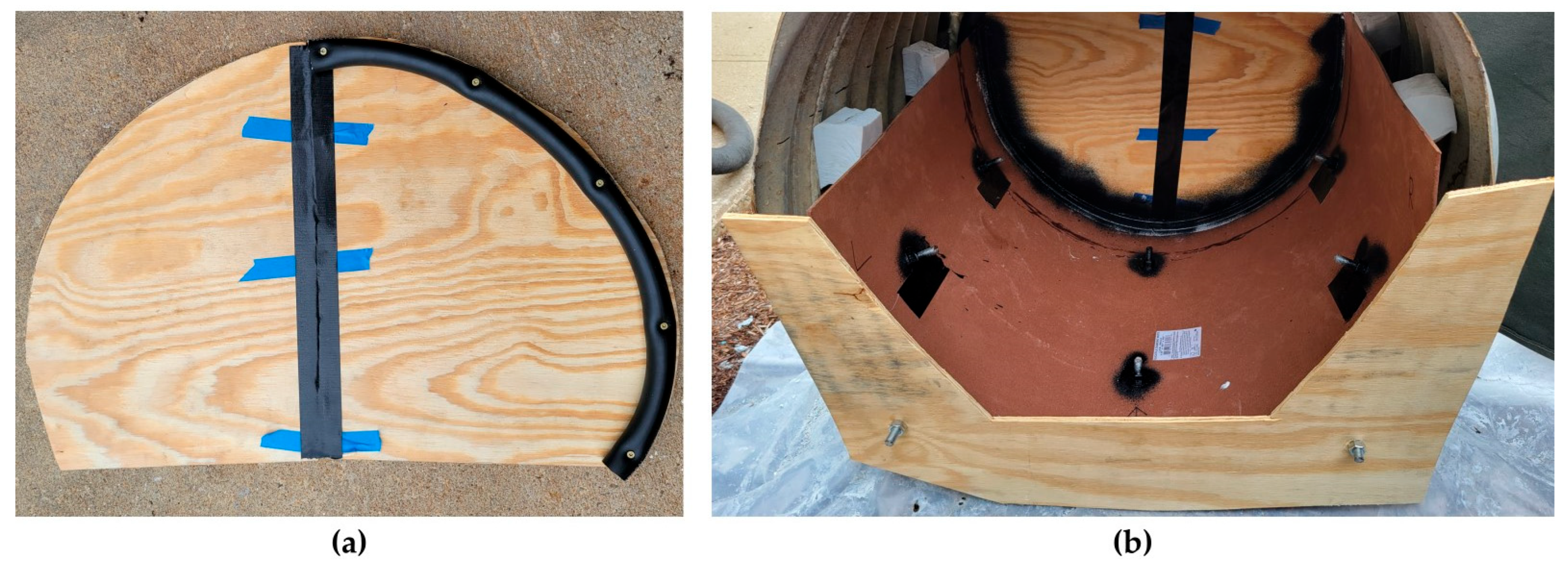
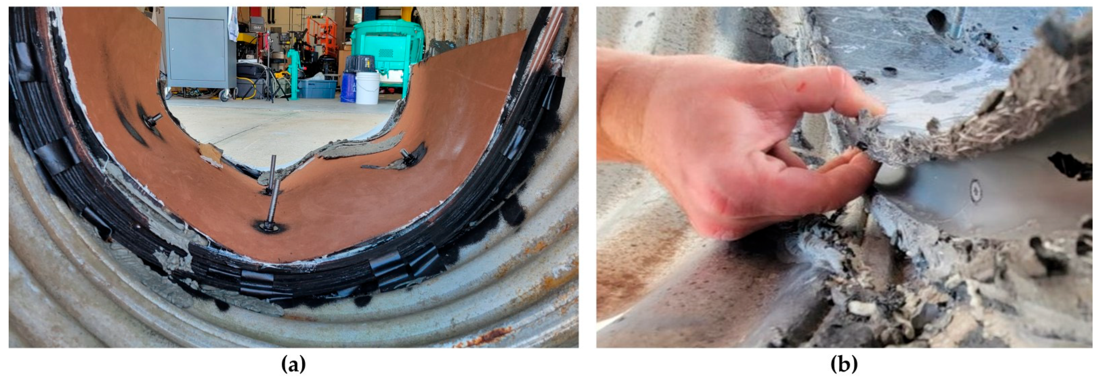
Details such as bulkheads, cold joints, and standoffs are also important to consider when designing formwork for UHPC invert lining. Due to the curvature of the culvert section, the bulkhead must be flexible, durable, and easy to insert. The MDF strips were both flexible and durable, but very time consuming to place, especially in a helically corrugated culvert, seen in the small-scale tests (
Figure 19a), as opposed to a circumferential corrugations seen in the large tests. The second small test, with a plywood bulkhead and attached rubber tube, exhibited a very clean keyway for subsequent UHPC pours to flow into (
Figure 19b). Ultimately, the rubber strips in the large-scale steel formed placement were ideal and did not break even after stripping the formwork and may be the most feasible for large scale implementation. The only drawback was a lack of intrusion into the UHPC that could form a mechanical joint.
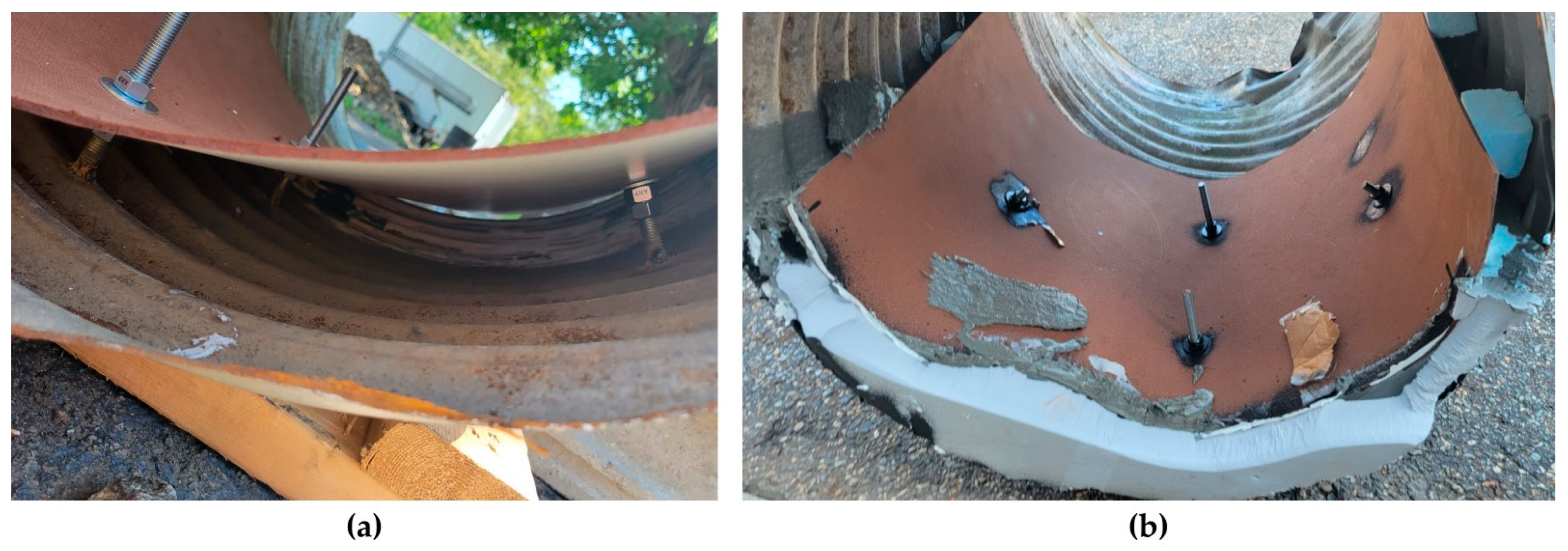
Formwork standoffs are another challenge that must be considered when designing a formed UHPC invert lining. Headed shear studs were very promising as they could act as both a formwork standoff and mechanical attachment for the UHPC, but due to the thickness of the culvert plate, it would be very difficult to utilize a standard stud welding gun due to the mechanized process involved in stud welding [
39,
40]. Additionally, the best practice for welding to galvanized steel recommends first surface grinding all zinc material off, which would further reduce the thickness. Although the tops of the studs were visible through the UHPC, raising concerns about potential corrosion paths, mitigative measures such as coating the studs or using stainless steel studs may be considered for future implementations. Threaded rods with nuts and washers can be considered a viable stand-off and hold-down method for wooden formwork, but may be less reliable for any other material, as they would require very exact placement to correctly pass through the formwork and be bolted in place. Fiberglass angles were successful in the large-scale wooden formwork and can be considered a long-term solution for a durable, high-strength standoff. In this project, the fiberglass angles were attached only to the welded wire mesh through twisted rebar ties, making them a non-structural component that could only act as a standoff. Alternative attachment methods, such as a 2” × 2” angle bolted directly to the culvert wall, may be able to act as structural attachments as well, but designers should carefully consider all options.
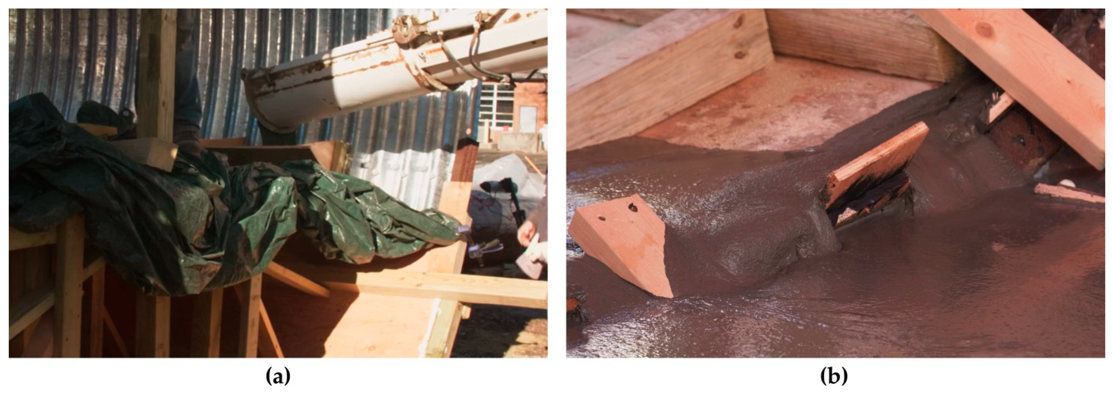
Formless casts for UHPC invert linings have the potential to greatly simplify the design and overhead of a culvert rehabilitation project. However, they are much more sensitive to the rheology of the UHPC, which in turn is sensitive to temperature, vibration, chemistry, and working time. Thixotropic UHPC was a promising solution to the task, and the researchers were successfully able to cast an invert lining over the test area. Preparation of the culvert was minimal, requiring only the welded wire mesh that was installed in each of the other tests. Mixing and moving the UHPC was a critical step that required the constant attention of the material supplier to ensure consistency and make on-site adjustments to the mix. The final step of mixing was completed in small batches, individually adjusted with admixtures to make it thixotropic. While this allowed the material supplier complete control and the ability to adjust the admixtures based on communication with the finishing crew, it is critical that this step be performed by personnel with significant experience. The fast-setting nature of UHPC, accelerated by the admixtures to reduce flowability, makes full experimental testing of each small batch difficult. The material supplier representative conducted empirical tests during mixing by picking up a handful of UHPC to feel its consistency and visually check how its rate of flow. This method requires significant knowledge and experience with the material, along with regular feedback from the finishing team to quickly make any adjustments. The thixotropic UHPC must be flowable enough to be discharged from the mixer but stiff enough to remain in place once cast. Upon recommendation from the material supplier, touchups and movement of the material once in place must be minimized, as an energy input increases and extends the flowability of the mixture [
41,
42]. However, due to the surface requirements of a culvert, the UHPC must be as smooth as possible to minimize the restrictions on water velocity. Any other smoothing or leveling techniques such as vibration may worsen the stiffness of the material. Overall, thixotropic UHPC is feasible as an invert and should be considered by designers, but with the caveat that the final surface may not be as smooth as top forming and must have an engineer with significant experience in mix design and placement.
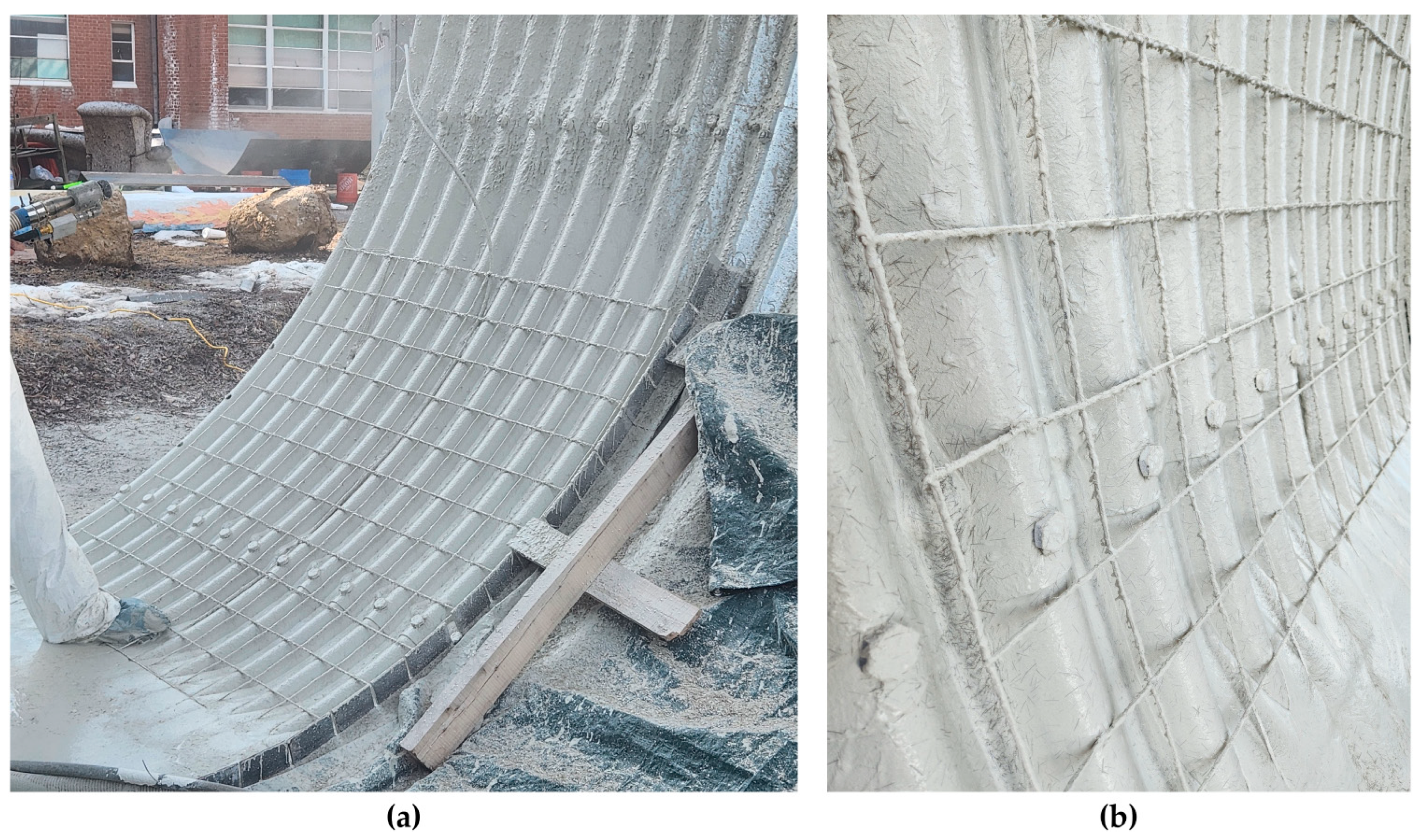
One of the final lessons from the placements was that UHPC shotcrete requires further development or mockup installation prior to field application. The consistency of UHPC is vital in the repair process. UHPC shotcrete needs a combination of high flowability through the pump and blower system and high stiffness upon contact with the culvert wall substrate. Two main issues were encountered in this project: the slow discharge of the UHPC and the flowability upon contact with the substrate. Due to the high concentration of fibers in UHPC compared to other shotcrete mixtures, the volume of UHPC that can be sprayed over a unit time is much lower than conventional shotcrete, greatly slowing down the process. The flowability of the mixture aids in the spraying process but causes the UHPC to flow down the sides of the culvert once placed and be unable to build up the required thickness. During testing, the UHPC was only able to build up a single layer of approximately 0.25 inches on the culvert wall. This was largely aided by the fibers providing some structure to the UHPC once they hit the wall of the culvert. There was no noticeable difference in UHPC build-up in places where the culvert steel was roughened with an angle grinder as recommended by the material supplier. Ultimately, only a quarter of the planned volume of UHPC was sprayed as it flowed down to the very base of the culvert and had extended to nearly three inches with no noticeable improvement on the wall layers.
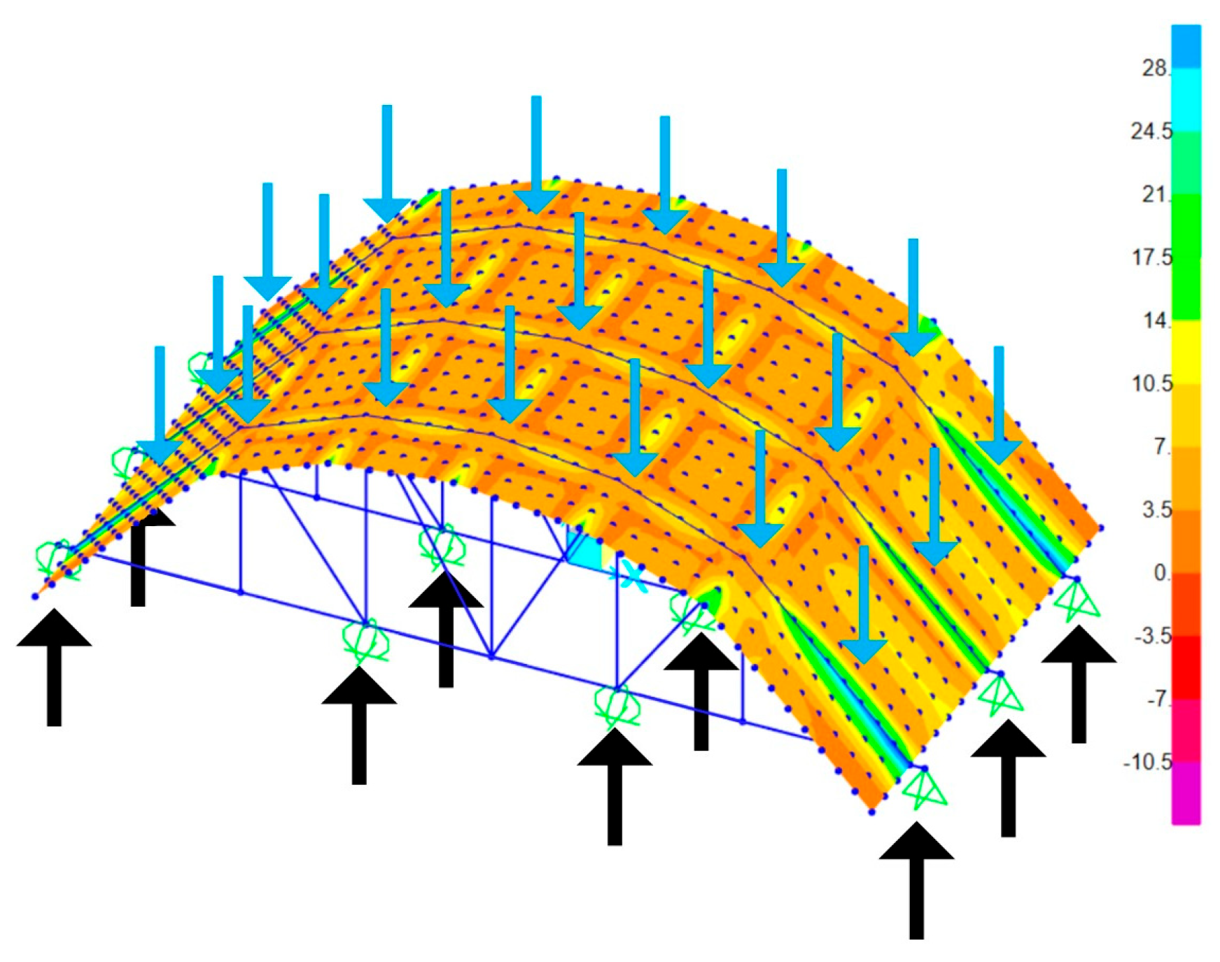
The findings from this study highlight several important future research needs to advance the application of UHPC invert linings in culvert rehabilitation. Further investigation is required to quantify the structural performance of the rehabilitated systems under service and extreme loading conditions, including both experimental load testing and advanced numerical simulations. Additional studies should also examine long-term durability, bond behavior, and interface performance between UHPC and existing substrates to ensure reliable field implementation. Finally, there is a need to evaluate construction methods and quality control procedures across a wider range of geometries, materials, and environmental conditions to support the eventual development of standardized design practices for UHPC rehabilitation systems.
