1. Introduction
The use of spiral curves promotes driver comfort and safety by ensuring consistency between the path intended by design and the actual steering path, while also enhancing the recognizability of the geometric layout. However, many existing primary and secondary roadways have been designed and constructed without the use of spiral curves between tangent and circular arc segments. Even today, numerous detailed design studies continue to directly connect tangents and circular arcs, as this approach is considered safe under certain conditions and does not significantly compromise driver comfort in all cases, and remains permissible under current geometric design guidelines.
The method proposed in this study is based on an analysis of vehicle dynamics and the required safety margins in curves, ensuring safety even under icy conditions—when the friction coefficient provided by the road surface is low—for maximum longitudinal slopes up to 9% in vertical alignment. It is also recommended for application on existing rural roads on mountainous terrain lacking spiral curves and exhibiting a high accident history.
The novelty of this methodology lies in its approach, which does not rely solely on driver behavior assessment but also incorporates established safety margins from existing design principles. The design is adjusted in such a way that drivers are not exposed to risk due to inconsistencies between the design and vehicle dynamics.
Requirements for design without spirals
AASHTO [
1], AUSTROADS [
2], RGDM [
3], and RDM [
4] guidelines specify an upper radius limit for the use of spiral curves, determined by an acceptable level of lateral acceleration experienced by drivers, typically around 1.3 m/s
2. Therefore, the minimum radius (R) at which a spiral curve can be omitted is derived by using the basic curve equation (Equation (1)), setting the side friction coefficient (fr) equal to 0.133 (1.3 m/s
2), and varies depending on the superelevation rate (q). India’s guidelines for expressways [
5] follow the same approach, but by setting zero friction factor (fr)/lateral acceleration.
where
V (km/h) is the design speed;
R (m) is the design radius of the curve;
FR is the side friction coefficient, which is converted to unbalanced lateral acceleration by multiplying with the acceleration due to gravity (g = 9.81 m/s2);
q is the design superelevation rate of the curve.
Existing methods for changing the superelevation rate
In the absence of spiral curves, all manuals recommend splitting the superelevation runoff length between the tangent and the curve. AASHTO [
1] guidelines advise a transition on the tangent section ranging from 50% to 80%, with 67% being the most adopted value. RGDM [
3] and RGM [
4] primarily adopt the 67% transition on the tangent. AUSTROADS [
2] prescribes a tangent transition of 70–80%, provided that the runoff section within the curve does not exceed 1 s at the design speed or a length of 30 m. The OMOE-X [
6], RAL [
7], and RAA [
8] recommend dividing the superelevation runoff length equally across the point of curvature without using a tangent runout section. The term runoff refers to the section where the pavement surface is rotated as a plane.
Safety assurance measures in design guidelines
The utilization factor (n) has been adopted by most road design manuals to ensure a greater safety margin. The performance-based rationale underlying this approach is consistent with driver behavior on curves with large radii and, more broadly, on curves with radii exceeding the minimum allowable, where the required design superelevation rate is lower than the maximum permissible value. Various studies [
9,
10,
11] report that on large radius values, road users tend to drive at speeds greater than the design speed. This implies that if the speed increases, then, according to Equation (1), the side friction demanded will also increase, and consequently, the demanded utilization factor will rise, reducing the safety margin in the longitudinal direction.
The side friction coefficient and the utilization factor are directly interrelated, as described by Equations (2) and (3). As the demanded side friction coefficient increases during the vehicle’s traversal of the curve, the utilization factor also increases. Consequently, the tangential friction coefficient provided (ft) decreases, an impact that is confirmed through Equation (4).
where
pt is the amount of the total friction coefficient provided in the tangential direction;
n is the amount of the total friction coefficient provided in the side direction and is widely called the utilization factor;
maxfr is the maximum allowable side friction coefficient;
maxf is the maximum total friction coefficient provided by the road pavement surface.
The OMOE-X [
6], RAL [
7], and RAA [
8] guidelines introduce an additional multiplicative factor of 0.925 into the original equation to account for tire characteristics, although this factor may be considered negligible.
Table 1 includes the design utilization factor values depending on the superelevation rate, the network context, and the roadway type (rural freeway or non-freeway highway, rural major or secondary arterial), setting some guidelines.
Since all methods recommended by international road design guidelines permit a portion of the runoff length to occur within the curve when spirals are omitted, the constraints mentioned above for the maximum allowable side friction (fr) are negated.
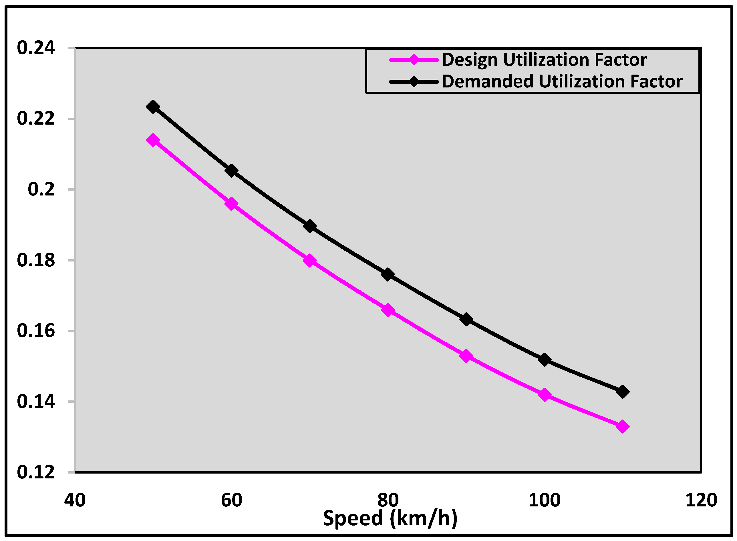
Figure 1 presents the average difference between the design and demanded utilization factors, as derived from the design guidelines, assuming the driver has already adjusted the steering to a constant path at the point of curvature. The demanded utilization factor values were obtained using Equation (3). Initially, Equation (1) was employed to calculate the side friction required at the point of curvature, which was then integrated into Equation (3) for the final computation.
According to the rationale of design manuals, the design utilization factor is assumed to take a lower value than the maximum, depending on the transition length, the differential superelevation, the design speed, and the geometric design. In contrast, based on the rationale of the present study, the demanded utilization factor resulting from the application of the manual-based methods is computed for a constant curvature—equal to the minimum one—and takes a value higher than the maximum. For these reasons, the resulting values are variable rather than constant, as currently assumed by the design manuals for the circular arc section.
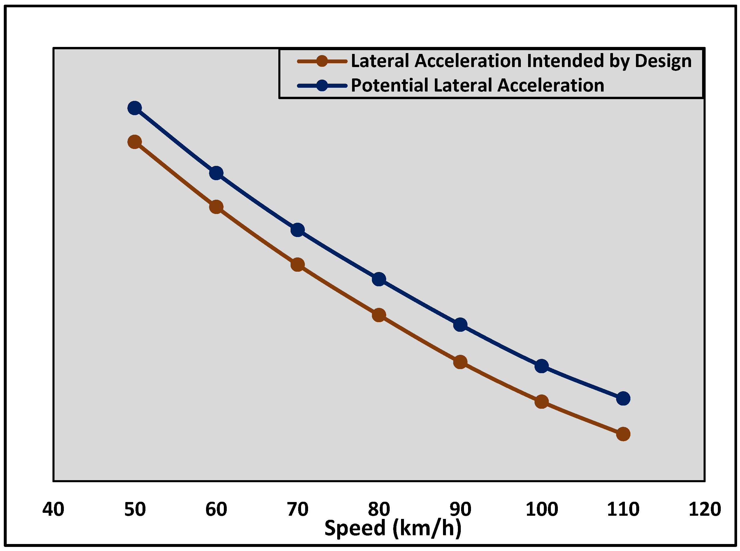
Figure 2 illustrates the potential impact on the lateral acceleration experienced by drivers due to the mismatch between the design and demanded utilization factors.
For both
Figure 1 and
Figure 2, values are indicative and are computed based on Equations (2) and (1), respectively, depending on the critical vehicle dynamics and geometric design parameters. The friction coefficient values were derived from either the Greek [
6] or German [
7,
8] design guidelines.
Figure 1 and
Figure 2 highlight the necessity of revising the rationale behind the horizontal placement of the runoff length. To avoid the additional lateral acceleration that results in an increased demanded utilization factor, the change in superelevation rate should occur entirely within the tangent section. The feasibility of such a method must be assessed by considering a set of critical parameters and driving scenarios.
Key parameters to be examined include the preservation of safety margins under wet pavement conditions and the effects of compound slopes, with the aim of ensuring that the vehicle remains fully stable under icy conditions, which represent the most adverse pavement surface scenario. Previous studies [
12,
13] have shown that the average coefficient of friction on icy surfaces is approximately 0.10, which supports the rationale behind standards such as OMOE-X [
6], adopting a maximum allowable compound slope of 10%.
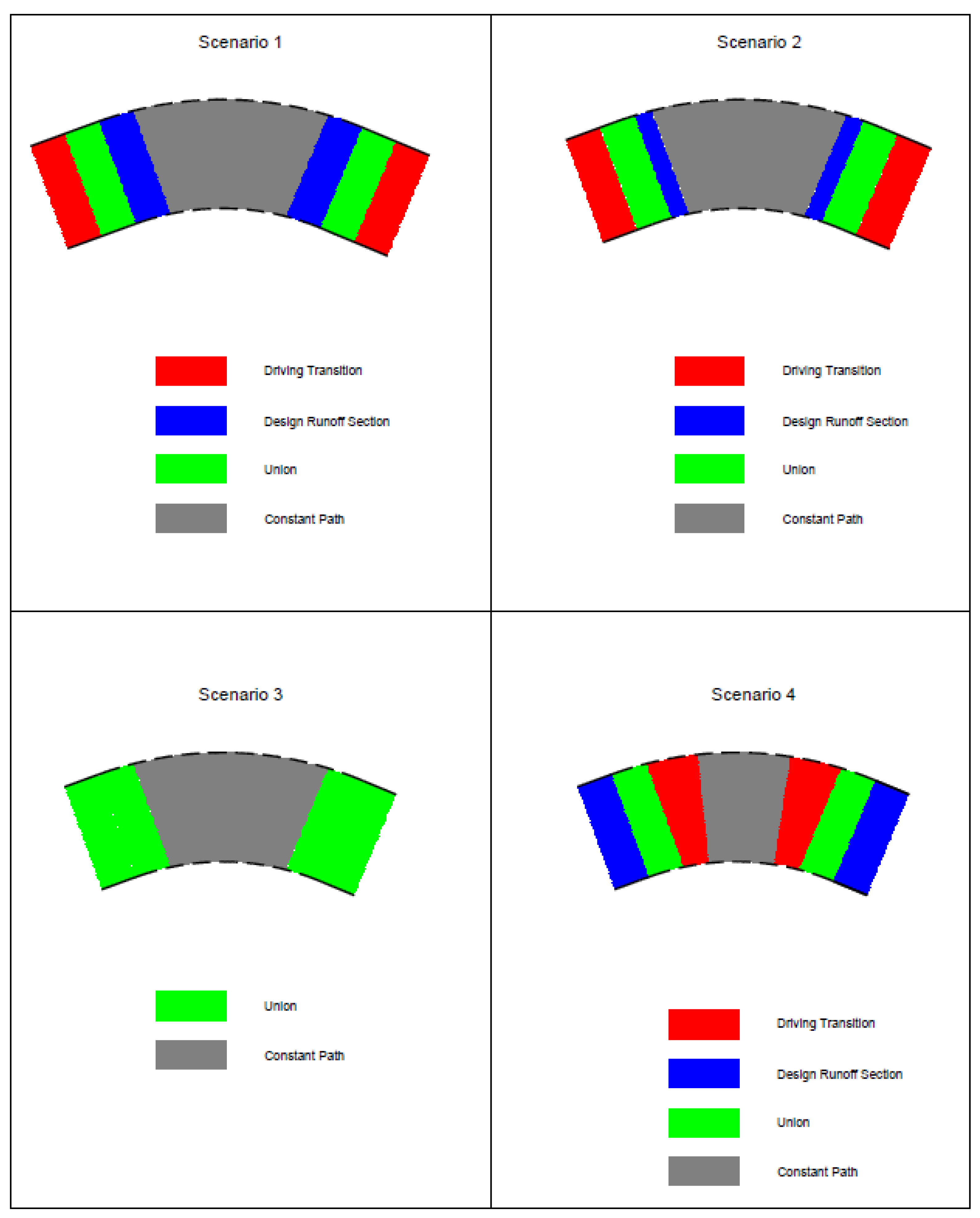
In the absence of spiral curves, there are four scenarios related to the driver’s transition path endpoint upon entering and an initial point upon exiting the curve.
Scenario 1: Transition Completion at the Point of Curvature
This represents the worst-case scenario and corresponds directly to the conditions illustrated in
Figure 1 and
Figure 2, given that the demanded utilization factor significantly exceeds the design value. The driver follows a constant curvature trajectory, while the design superelevation rate is lower than the required value. As a result, lateral acceleration reaches its maximum value, exceeding the design threshold at the point of curvature. In this scenario, the entry transition ends precisely at the point of curvature, while the exit transition begins at the corresponding point symmetric to the midpoint of the arc.
Scenario 2: Transition Completion within the Circular Arc but in Harmful Mismatch with the Runoff Section
This is the second most adverse scenario. The driver follows a variable curvature transition at the point of curvature. However, in the case of entry, the path completes before the maximum superelevation is attained, and in the case of exit, the transition begins after the initial point of the runoff section. Consequently, the driver still experiences a peak in lateral acceleration at the segment of constant curvature with an inadequate superelevation rate (lower than in Scenario 1), but higher than what is permitted by the geometric design.
Scenario 3: Transition Completion at the Start or End of the Runoff Section
This is the scenario upon which most design guidelines are based. The driver maintains a constant path within the circular arc segment, where the superelevation rate is also constant, and adjusts the steering in the same manner as the runoff section. In practice, however, an exact alignment between the theoretical design runoff section and the actual transition path is unattainable, especially in the absence of spiral curves.
Scenario 4: Transition Completion within the Circular Arc but in Beneficial Mismatch with the Runoff Section
This is the most favorable scenario. The driver’s constant path begins or ends within the section where the superelevation rate has already attained the maximum value, thereby reducing the length over which the maximum design lateral acceleration is experienced. This scenario is only realistic in cases of large curve radii and small deflection angles.
Numerous intermediate scenarios may be formed through various combinations of design runoff section and actual transition. However, the classification into these four scenarios effectively covers the full methodology and reasoning behind identifying the appropriate runoff section.
Figure 3 illustrates these four scenarios over a simple horizontal curve between two tangent sections. The “driving transition” section corresponds to the portion of the alignment where the driver follows a variable curvature steering, while the “runoff” section refers to the segment where the design manuals consider appropriate for changing the superelevation rate. For simplicity, the standards of OMOE-X [
6], RAL [
7], and RAA [
8] are used to represent the method. The union of the aforementioned sections in the figure indicates that changes in both the superelevation rate and the driving curvature occur simultaneously. Hence, as the length of the constant curvature path within the circular arc decreases, the associated risk also diminishes.
2. Methodology
Considering the most critical of the analyzed scenarios (Scenario 1), it was deemed necessary to investigate the implications of applying the maximum superelevation rate at the point of curvature, given that the design superelevation rate does not exceed 5%. This enables the implementation of longitudinal gradients up to 9%, a value deemed acceptable for alignments in mountainous terrain with design speeds of up to 80 km/h, according to the Greek OMOE-X [
6] guidelines.
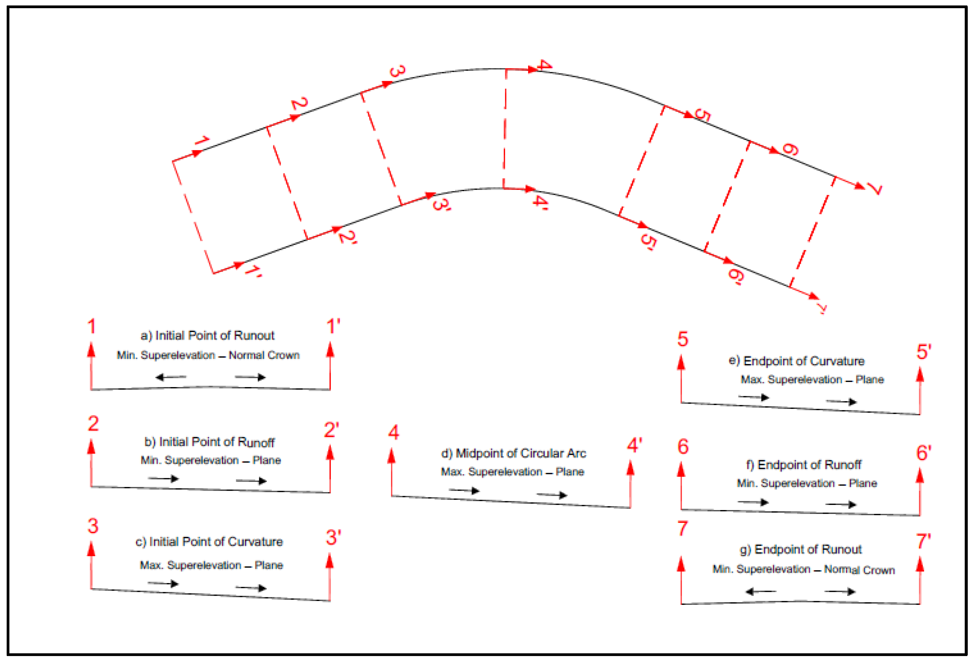
The method illustrated in
Figure 4 effectively shifts the runoff section outside the circular arc, allowing the driver to experience a constant lateral acceleration equal to the maximum design value within the arc, without requiring an increase in the demanded utilization factor. In this manner, the proposed method encourages a revision of design manual rationales regarding superelevation rate changes, setting the tangent section as the critical segment and minimizing changes within the circular arc whenever possible.
The most adverse cases that may arise include either (i) the driver following a less consistent transition path upon curve entry, which induces an abrupt splicing with a sharper radius or (ii) completing the transition path either before the point of curvature during curve entry or after it during curve exit, respectively.
The first case cannot be addressed through runoff design alone, as only the implementation of spiral curves can adequately optimize this condition. The second case could potentially be mitigated by further moving the runoff section away from both points of curvature, particularly in curves with large deflection angles, where such incidents are more likely.
Setting the convention of a one-way road for simplifying the terms of initial, mid, and end points, seven critical cross sections are distinguished:
Initial Point of Runout: It is in the tangent section. This point exists only when the tangent section has a normal crown or a planar cross slope with a superelevation direction opposite to that required in the circular arc. In all other cases, it is eliminated.
Initial Point of Runoff: Located in the tangent section preceding the circular arc. This point marks the beginning of the superelevation critical transition. It is defined as either of the following:
Last cross section with a superelevation rate recommended for exclusive tangent sections (in the case of planar normal cross slopes, irrespective of superelevation direction);
First point at which the entire roadway surface begins to rotate as a plane (in the case of normal crown cross slopes).
Initial Point of Curvature: It is the point at which the maximum superelevation rate is attained, coinciding with the end of the runoff section. It marks the beginning of the circular arc.
Midpoint of Circular Arc: This point represents the typical condition of the superelevation design within the circular arc. It is often used as a reference for evaluating geometric consistency and lateral acceleration.
Endpoint of Curvature: This is the point at which the maximum superelevation rate is still maintained and, in this case, coincides with the beginning of the runoff section leading into the exit tangent.
Endpoint of Runoff: It is a point of tangent section, which could constitute the
The final point at which the roadway surface is rotated as a plane;
The point where the superelevation direction aligns with that of the preceding curve, adopting the typical value for a tangent section but oriented opposite to the typical cross slope;
The point where the tangent regains its typical superelevation value and direction.
Endpoint of Runout: Similarly to the initial point of runout, this point only exists in cases with a normal crown or a planar cross slope whose superelevation direction is opposite to that of the preceding circular arc. Otherwise, it is omitted.
Those cross sections could be reduced to the four, provided that the relative gradient (Δs, Equation (5)) maintains a constant value and the following combined conditions are met:
- (i)
The length of the runoff section is the same for both the entry and exit sections.
- (ii)
The differential superelevation rate is also equal.
- (iii)
The normal cross slope at the tangent sections is either identical, a normal crown, or a plane.
- (iv)
The base width of the cross section does not vary across the circular arc.
Δs is the relative gradient (positive or negative, depending on the sign of the gradient in the axis of rotation);
Δq is the differential superelevation rate during the full roadway rotation;
L is the length of runoff sections;
A is the distance between each edge and the axis of rotation.
3. Results
The applicability of the proposed method and its impact on driver comfort and safety can only be evaluated by examining its effects on the demanded utilization factor, the deviation between the lateral acceleration intended by design and the one experienced by drivers, and the safety margins maintained under icy pavement conditions.
The comparative assessment between the design and demanded utilization factor is presented in
Table 2, and the results are based on the superelevation rate attained at the point of curvature (
Table 3). It is observed that the method proposed in this study contributes to a balanced relationship between the demanded and design utilization factors in all cases where the design superelevation rate on the curve is up to 5%.
For the European guidelines, the most critical direction analyzed is the one on the outer side of the curve ahead or behind. For those guidelines (OMOE-X [
6], RAL [
7], and RAA [
8]), the proposed method yields a demanded utilization factor at least 30% lower, even under the most critical Scenario 1. When compared to non-European guidelines, the demanded utilization factor is found to be approximately 15% lower.
By applying Equation (3), a corresponding reduction is also observed in the demanded side friction coefficient, which, when multiplied by gravitational acceleration, represents the lateral acceleration experienced by drivers at the point of curvature.
The comparative evaluation of the methods in terms of the safety they provide under icy pavement conditions is not conducted using any of the four realistic scenarios analyzed above, as all assume a curved driving path at the points of curvature, which, according to Equation (1), entails a certain level of lateral acceleration depending on vehicle speed.
However, when evaluating marginal conditions on icy road surfaces, where speeds on curves are typically low, the presence of lateral acceleration may, in many cases, have a beneficial effect, as it prevents vehicle sideslip toward the inner side of the curve due to excessive superelevation.
For this reason, a fifth, more critical scenario is considered, which assumes that the driver has not yet initiated the steering path at the point of curvature.
Table 4,
Table 5 and
Table 6 present the resulting values of compound slope, composed of the longitudinal grade and the superelevation (traversal slope), for various longitudinal slope values up to the most common upper allowable threshold of 9%.
It is observed that even for the maximum longitudinal slope of 9%, the maximum allowable compound slope of 10% is practically not exceeded. Furthermore, the deviation between the maximum compound slope allowed by current international design guidelines and the one resulting from the proposed method ranges between 0.5% and 1%. This corresponds to a difference of approximately 0.005 to 0.01 in the total demanded friction coefficient.
4. Discussion
The proposed methodology can significantly enhance safety and comfort in the design of direct tangent-to-curve transitions, particularly on existing two-lane rural roads in mountainous terrain without substantial increases in construction cost. In such rural roads (one lane per direction), implementation can be achieved with minimal construction impact, primarily involving the replacement of asphalt pavement layers and, if necessary, partial removal of the upper base course layer, replacement of shallow triangular gutters, and possibly inclusion of localized widening or higher-capacity drainage channels.
Its applicability extends to new roads where spiral curves are omitted. This methodology can be successfully applied to new roadway projects constructed on bridges, particularly in urban environments where the use of precast beam structures limits the available deck width and construction tolerances, thereby preventing the implementation of spiral curves. However, its application to existing bridge or tunnel facilities is challenging due to operational constraints and the concurrent reconstruction of the surrounding network.
Adoption of this method would eliminate sections where driver safety may be compromised under wet conditions, especially when speeds exceed the design speed and design parameters approach critical limits, as well as sections where lateral acceleration adversely impacts driver comfort.
Regarding safety and comfort under wet pavement conditions, this method outperforms current geometric design guidelines, especially European standards such as OMOE-X [
6], RAL [
7], and RAA [
8]. Although other international guidelines [
1,
2,
3,
4] may better approximate safety concerns, the proposed method still offers notable advantages.
The compound slopes calculated in
Table 4,
Table 5 and
Table 6 correspond to the demanded side friction coefficient needed to prevent vehicle sliding, assuming a constant tangential driving path at the point of curvature. Despite the conservative nature of this scenario—requiring special conditions under which the driver has not yet initiated the steering path (transition or constant) due to limited sight distance from vertical alignment constraints—this methodology still meets the safety requirements for the maximum demanded side friction coefficient.
Special attention is required for low-volume rural roads, where the relative gradient (Δs) may be increased, potentially affecting the compound slope in the vehicle’s motion axis near the point of curvature.


