Article

A Systematic Approach for Selection of Fit-for-Purpose Low-Carbon Concrete for Various Bridge Elements to Reduce the Net Embodied Carbon of a Bridge Project

by
Harish Kumar Srivastava
*,
Vanissorn Vimonsatit
and
Simon Martin Clark
School of Engineering, Macquarie University, Macquarie Park, NSW 2113, Australia
*
Author to whom correspondence should be addressed.
Infrastructures 2025, 10(10), 274; https://doi.org/10.3390/infrastructures10100274
Submission received: 22 July 2025 / Revised: 21 September 2025 / Accepted: 9 October 2025 / Published: 13 October 2025
(This article belongs to the Special Issue Sustainable Bridge Engineering)

Abstract

Australia consumes approximately 29 million m3 of concrete each year with an estimated embodied carbon (EC) of 12 Mt CO2e. High consumption of concrete makes it critical for successful decarbonization to support the achievement of ‘Net Zero 2050’ objectives of the Australian construction industry. Portland cement (PC) constitutes only 12–15% of the concrete mix but is responsible for approximately 90% of concrete’s EC. This necessitates reducing the PC in concrete with supplementary cementitious materials (SCMs) or using alternative binders such as geopolymer concrete. Concrete mixes including a combination of PC and SCMs as a binder have lower embodied carbon (EC) than those with only PC and are termed as low-carbon concrete (LCC). SCM addition to a concrete mix not only reduces EC but also enhances its mechanical and durability properties. Fly ash (FA) and granulated ground blast furnace slag (GGBFS) are the most used SCMs in Australia. It is noted that other SCMs such as limestone, metakaolin or calcinated clay, Delithiated Beta Spodumene (DBS) or lithium slag, etc., are being trialed. This technical paper presents a methodology that enables selecting LCCs with various degrees of SCMs for various elements of bridge structure without compromising their functional performance. The proposed methodology includes controls that need to be applied during the design/selection process of LCC, from material quality control to concrete mix design to EC evaluation for every element of a bridge, to minimize the overall carbon footprint of a bridge. Typical properties of LCC with FA and GGBFS as binary and ternary blends are also included for preliminary design of a fit-for-purpose LCC. An example for a bridge located in the B2 exposure classification zone (exposed to both carbonation on chloride ingress deterioration mechanisms) has also been included to test the methodology, which demonstrates that EC of the bridge may be reduced by up to 53% by use of the proposed methodology.

1. Introduction

The Australian Government has committed to achieving net-zero emissions by 2050. It is reported that in 2023, the transport sector was the third-largest greenhouse gas (GHG) emitter and was responsible for 21% of Australia’s greenhouse gas emissions. The estimated embodied emissions from the delivery and construction of transport infrastructure are 3% of Australia’s total greenhouse gas emissions [1]. The life cycle embodied carbon comprises upfront carbon associated with the product and construction stages (A1–A5), in-use stage (B1–B5), and end-of-life stage (C1–C4) [2]. The embodied carbon associated with the product development stage (A1–A3) is 84% of the total upfront carbon. Out of this, the contribution of concrete and reinforcing steel is 55% and 26%, respectively [2]. This implies that lower-carbon materials need to be used for the decarbonization of the construction sector.
Australia consumes approximately 29 million m3 of concrete each year with an estimated embodied carbon (EC) of 12 Mt CO2e. Portland cement (PC) constitutes only 12–15% of a concrete mix but is responsible for approximately 90% of concrete’s EC. High consumption of concrete inter alia PC makes it critical for successful decarbonization and supporting the achievement of ‘Net Zero 2050’ objectives of the Australian construction industry. Australian annual consumption of PC was approximately 10.2 million tonnes in 2020–2021 (https://cement.org.au, accessed on 13 September 2025). In Australia, 60% of PC is manufactured using domestic clinker, and 40% is based on imported clinker. CO2 emission factor for domestically produced clinkers is 791 kg CO2/t of clinkers [3]. This report envisages that CO2 emissions may be reduced by up to 41% by adopting innovative design and construction methods and concrete/PC material technology [3]. CO2 emission factor of Australian PC varies from 696 to 1098 kg CO2/t [4]. Conventionally, concrete is produced using PC as binder, and supplementary cementitious materials (SCMs) are added to enhance fresh, hardened, and durability properties without any consideration to EC reduction. The mix design for concrete is typically focused on compliance with standards and specifications.
Low-carbon concrete (LCC) is produced utilizing SCMs to replace PC to enhance the fresh, mechanical, and durability properties of concrete while maximizing the embodied carbon (EC) reduction for the sustainability benefits. Fly ash (FA), granulated ground blast furnace slag (GGBFS), and silica fume (SF) are conventionally used SCMs in Australia. Australian Technical Infrastructure Committee (ATIC) specification, Section SP43 [5] limits the maximum replacement of PC by FA, GGBFS, and SF to 40%, 70%, and 10% in binary blends and FA + SF, GGBFS + SF, and FA + GGBFS to 34%, 54%, and 70%, respectively, from mechanical and durability performance considerations. These limits specified by ATIC SP43 may potentially be used for designing a fit-for-purpose LCC to maximize the PC replacement with SCMs, inter alia, minimizing the EC of concrete. Australian concrete suppliers have developed low-carbon concrete mixes such as Ecotera [6], Envisia [7], etc., using a high proportion of SCMs in the binder. These mixes have primarily been developed for building infrastructures, which are typically designed for a 50-year service life, and further investigations will be required to confirm their suitability for use for bridges with a ≥100-year design life. This research paper presents a systematic approach for selecting a fit-for-purpose LCC suitable for a 100-year design life bridge structure elements without compromising their functional performance. This approach is likely to minimize the overall EC of a bridge structure. This methodology may be used for other infrastructures, including buildings, concrete retaining walls, liquid retaining structures, and general concrete structures.

2. Performance Requirements for Concrete Bridges

2.1. Performance Requirements Establishment Process

A conceptual process for establishing the performance requirements for a bridge is given in Figure 1. These requirements may be used for selecting a fit-for-purpose concrete mix for various elements of a bridge or any other infrastructure.

2.2. Design Life

The performance requirements for a bridge are established considering the mode of transport for which the bridge is required to service, the environment the bridge is to be constructed, the construction methodology program, etc. In Australia the minimum design life of rail and road bridges is specified as 120 years and 100 years, respectively, specified by Australian Standards AS 5100.2 [8] and transport authorities’ specifications, including Transport for New South Wales (TfNSW) QA Specification TS 01733.1 (B80) [9], Queensland Department of Transport and Main Roads [10], etc.

2.3. Material Characteristics

The properties of concrete constituents, including aggregates and SCMs, vary significantly. The quality and consistency of constituents are critical for achieving the required mechanical strength and durability properties of concrete. It is therefore prudent to implement a project-specific quality control and testing protocol to ensure compliance with critical material characteristics specified in relevant standards and authority specifications, as given below.
  • Aggregates
    The quantity passing the 75 µm sieve shall not exceed 2% of the total coarse aggregate (by mass).
    The maximum water absorption shall be 2.5% except for slag aggregate, where the maximum water absorption may be up to 6%.
    The quantity of clays in fine aggregates shall not exceed 5% by mass, and the quantity of reactive clays shall not exceed 2.0% when the fine aggregate is tested by X-ray diffraction (XRD)/X-ray fluorescence (XRF).
  • Alkali–aggregate reaction (AAR) expansion in 21 days, measured by accelerated mortar bar test (AMBT) as per AS 1141.60.1 [11], shall be <0.1% for non-reactive aggregates, between 0.1% to 0.3% for slowly reactive aggregates, and >0.3% for reactive aggregates. For reactive aggregates, blended cement with a minimum of 25% FA or 50% GGBFS is used in production of concrete.
  • FA used as SCM in concrete shall be of grade 1 as per AS/NZS 3582.1 [12] with fineness (% passing 45 µm sieve) < 75%, loss of ignition (LOI) < 4%, moisture content < 1% and SO3 content < 3%. Total content of SiO2, Al2O3, and Fe2O3 in FA, determined by XRF tests, shall be >70%. The reactivity of FA, measured as the strength index, shall be >75%.
  • GGBFS used as SCM in concrete shall comply with AS 3582.2 [13]. The sulfide sulfur (S), magnesia (MgO), and alumina (Al2O3) content in GGBFS, determined by XRF tests, shall not exceed 1.5%, 15% and 18%, respectively.

2.4. Exposure Classification and Minimum Requirements

The durability of the bridge depends on the climatic zone and sub-soil conditions at the bridge site. Australian Standard AS 5100.5 [14] subdivides the country into three zones, viz., tropical, temperate, and arid zones, to assign exposure classifications as presented in Table 1. The minimum requirements for the concrete mix envisaged by AS 5100.5 for various environmental exposure classifications are presented in Table 2. It is noted that these minimum requirements do not cover the special requirements for precast concrete, for which early strength demand is higher than that for in situ concrete. Precast concrete requires accelerated heat curing to achieve the early strength demand. However, cast-in situ concrete is subjected to curing by normal water or curing compound addition. It is noted that the minimum requirements given in Table 2 do not include requirements for the infrastructures subjected to abrasion, freezing—thawing cycles, and concrete structures exposed to chemically aggressive soil conditions. Transport Authority specifications, including TfNSW-B80, 2020 [9], provide separate requirements for cast-in-place and precast concrete for managing fresh and durability properties of concrete to achieve the envisaged service life as given in Table 3. In addition to the minimum requirements, it also specifies maximum binder content as 400 to 550 kg/m3 for cast-in-place and 600 kg/m3 for precast concrete.
AS 5100.5 and Transport Authorities specifications allow the use of SCMs in concrete mixes but limit the maximum percentage of SCMs in the binder as presented in Table 4, to ensure that both fresh and hardened concrete meet performance requirements during the service life. SCMs also help in mitigating the alkali aggregate reactivity (AAR) in concrete (TfNSW-B80, 2020). AS 5100.5 specifies a minimum percentage of FA, GGBFS, and SF as 25%, 50%, and 8%, respectively, to mitigate AAR. Australian Standards allow the use of pozzolans other than FA, GGBFS, and SF if they comply with AS 3582.4 [15] Supplementary Cementitious Materials (Pozzolans–Manufactured).
AS 5100.5 recommends the required cover to reinforcement for each exposure classification zone mentioned in Table 1 for various types of formworks to ensure protection against carbonation and chloride ingress. The required cover for reinforcement for standard formwork and compaction is presented in Table 5.

3. Embodied Carbon (EC)

EC refers to ‘cradle to gate’ carbon emission from the material production stage and includes the GHG emission during raw material harvesting/ supply (A1 stage), transport (A2 stage), and manufacturing (A3 stage). EC represents equivalent greenhouse gas (CHG) emission and is expressed as kgCO2e. The AusLCI database [16] is considered the most appropriate database in the Australian context because it includes the Australian material production process, is updated regularly, and is being used by sustainability rating agencies such as the Infrastructure Sustainability Council of Australia (ISCA) [4]. In this study, EC of concrete mixes has been assessed considering the carbon emission factors from the AusLCI database supplemented with additional data sourced from shadow databases and the published literature, as given in Table 6. This table shows that EC of FA and GGBFS, which are commonly used SCMs in Australia, are only 2% and 21% of PC and will be effective in lowering the EC of concrete when used to replace PC in binary or ternary blends.
A simplified embodied carbon calculator based on Equation (1) has been used for evaluating the embodied carbon of concrete mixes.
E C C o n c r e t e = k = 0 n W k   ×   X k
W = weight of constituent, Xk = EC factor of constituent (Table 6), k = material id, and n = number of constituents in concrete mix.
The effect of replacement of PC with FA and GGBFS is presented in Figure 2 below, considering a total binder content of 450 kg CO2e/m3. It may be seen from this figure that the EC of concrete will not become zero even if PC is fully replaced by SCMs. It is noted that some PC will be required in a concrete for initiating the pozzolanic reaction. Alternatively, an alkali activator may be added to initiate the pozzolanic reaction.

4. Alternative Concrete Mixes with SCMs

4.1. Fly Ash Concrete

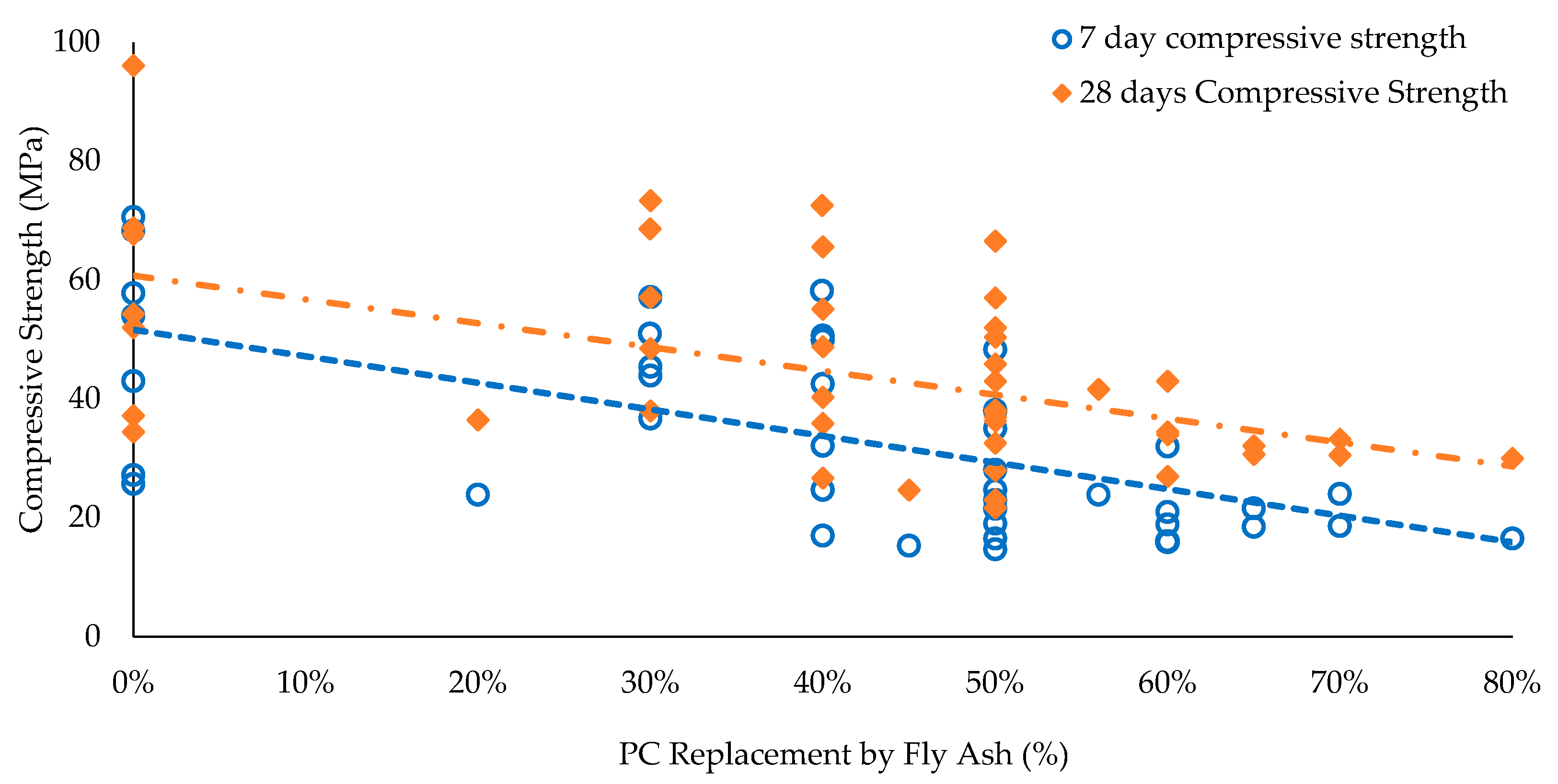
Fly ash (FA) is a by-product of coal-fired electric and steam-generating plants. Class F fly ash (CaO content < 10%) is generally used in concrete as a pozzolan or SCM to partially replace PC. EC of FA is only 20 kg CO2e/t, which is only 2.2% of PC and therefore is very effective in reducing the EC of concrete. The benefits of FA addition to PC concrete include improved fresh, mechanical, and durability properties (viz. improved workability, reduced bleeding, reduced heat of hydration, higher ultimate strength, reduced shrinkage, reduced permeability, increased resistance to sulfate attack and alkali–silica reactivity (ASR), and increased durability), and lowered cost and embodied carbon. The compressive strength of concrete mixes with various w/b and various levels of replacement of PC with FA is given in Figure 3. It is noted that typically, the compressive strength of concrete with a low w/b ratio is higher than that with a higher w/b.
Figure 3 presents the compressive strength of concrete for w/b from 0.24 to 0.6. The compressive strength varying from 21 MPa to 96 MPa was observed due to w/b variation at various levels of replacement of PC with FA. This is depicted by multiple compressive strength data points at a PC replacement level. It is noted that some variation in compressive strength may also be attributed to the variation in physical and chemical properties of FA used by various researchers.
Figure 3 may be used for designing a fit-for-purpose FA concrete mix, considering the strength requirements at various ages. This data will assist in planning formwork stripping and load transfer stages.
The chloride diffusion coefficient is a key indicator of concrete durability, as it governs the rate at which chlorides penetrate the substrate material and determines the time required for initiating the corrosion. Reinforced concrete with steel bars can be damaged due to chloride attacks, as chloride ions destroy the passive oxide layer of steel. Chloride-induced corrosion damage mostly occurs in structures exposed to aggressive marine environments. Test method ASTM C1202 is generally used for Rapid chloride permeability testing (RCPT), which involves measuring the electrical conductivity of concrete samples. Table 7 is used for interpreting the vulnerability of concrete.
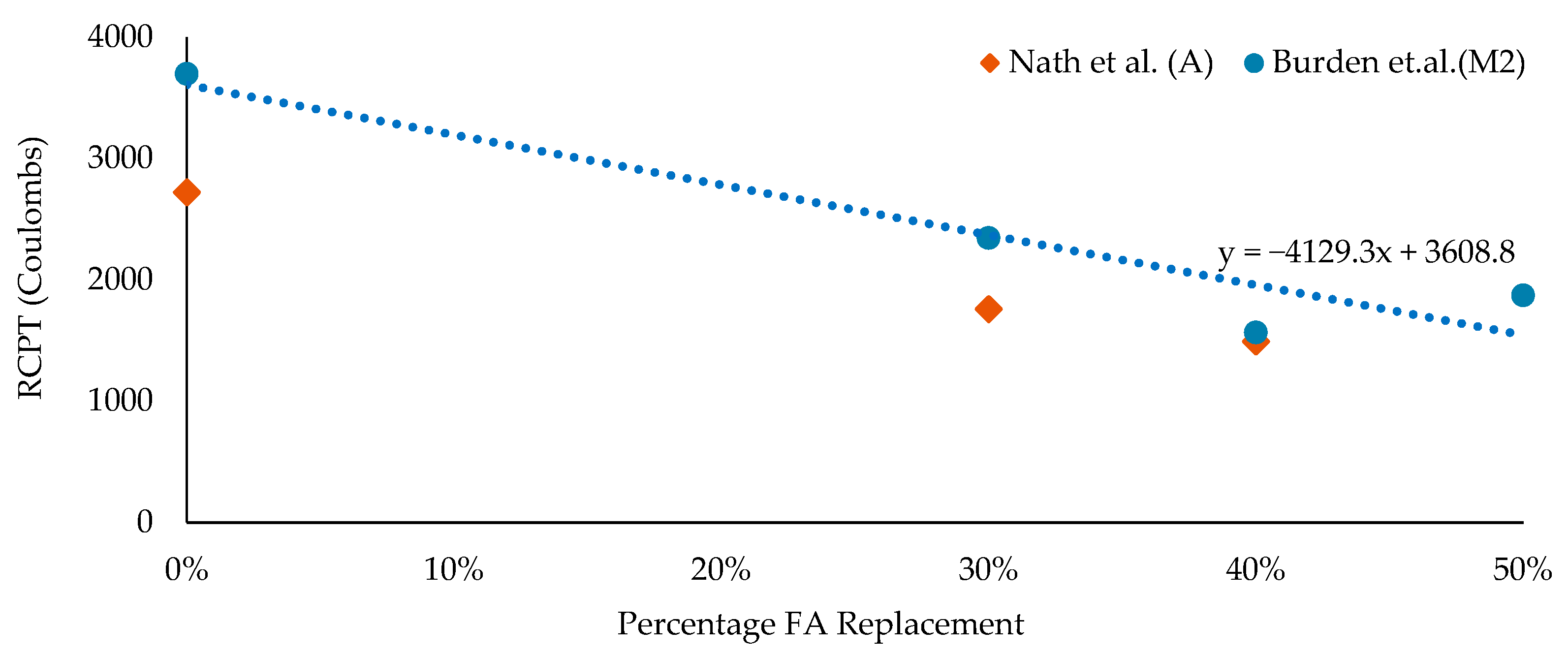
Figure 4 shows the relationship between RCPT and percentage of PC replacement with FA, which may be used for assessing relative chloride resistance of FA concrete mixes.
It was reported by (von Greve-Dierfeld et al., 2020) [25] that in PC-based systems, the carbonation proces involves reaction of dissolved carbonates with cementitious products, mainly through interaction with calcium ions that are extracted from hydrate phases. Once CO2 enters the substrate material, at pH > 10, gaseous CO2 rapidly dissolves into the alkaline pore solution and subsequently hydrolyses to bicarbonate (HCO3) and carbonate ions (CO3). During the carbonation process mono-carbonate is consumed first, followed by portlandite, strätlingite, and hydrotalcite, and the pH reduces from approximately 12.5 to 8.5, and C-S-H decalcifies to a Ca/Si of around 0.67. Fick’s first law of diffusion, as given in Equation (2), is generally used for determining the carbonation rate.
X c t = 2 · D c   ·   c s   ·   t a c = 2 ·   c s   ·   t R c a r b = k ·   t
  k t = k 0   ·   t n
where Xc = carbonation depth (m); Dc = diffusion coefficient of CO2 (m2/s); cs = CO2 concentration at the concrete surface (kg/m3); ac = amount of carbonatable material per unit volume (kg/m3); t = time (s); Rcarb = carbonation resistance ((kg/m3)/(m2/s)) = ac/Dc, k = carbonation coefficient (m/s1/2) = (2.cs /Rcarb); and n = 0 to −0.2 (to account for the pore blockage by reaction products).
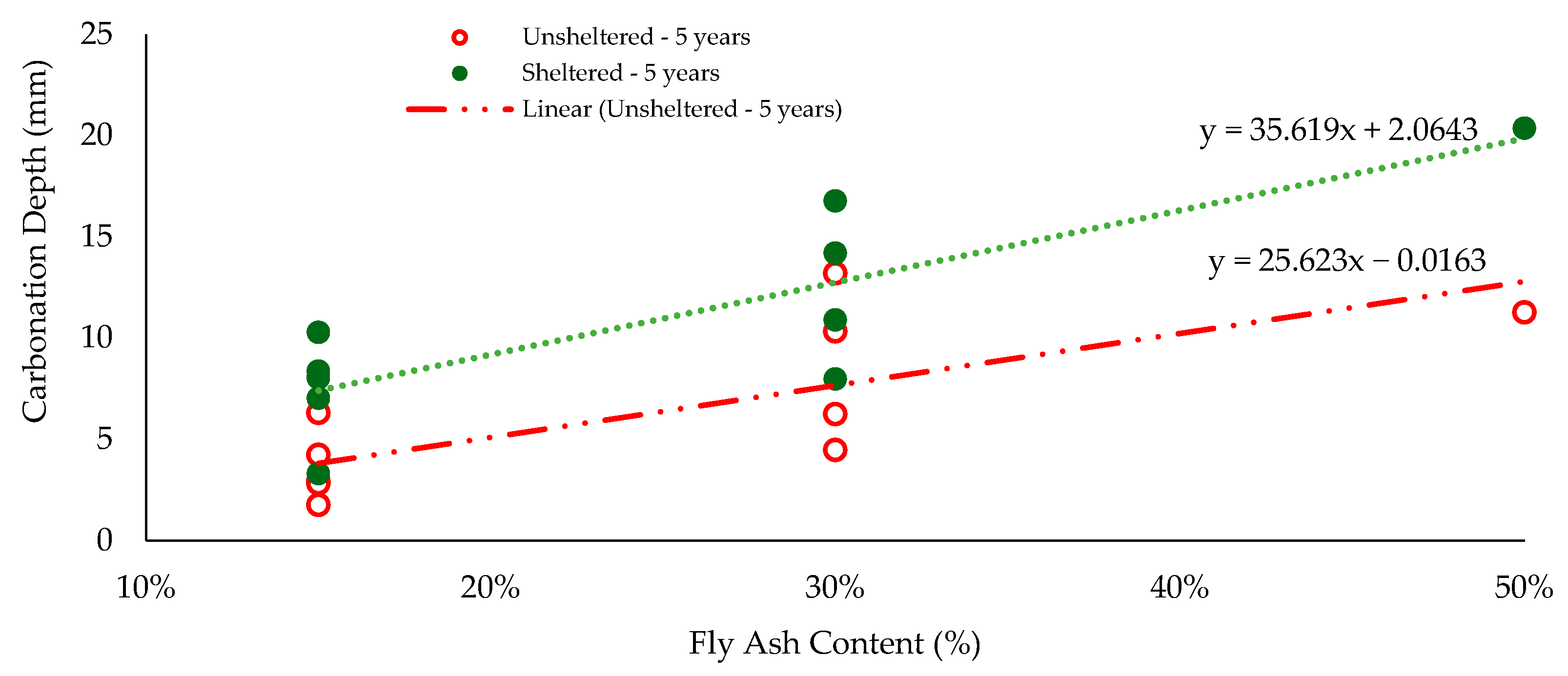
The porosity of PC concrete with SCMs generally increases upon carbonation. In PC blended with siliceous SCMs, the portlandite content is reduced due to pozzolanic or latent-hydraulic reactions. The required ratio of Class F-FA to total binder content for complete consumption of portlandite is approximately 35% (by weight). The carbonation rate of FA concrete increases with an increase in FA content, but the chloride resistance improves with an increase in FA content [18,20,21]. Huy Vu et al., 2019 [26], reported the carbonation depths for concrete specimens from 45 different mixes prepared centrally in Lafarge Centre de Recherche (France) and exposed to climate conditions at 4 laboratories located in Lyon (France), Austin (USA), Chennai (India) and Shanghsha (China) in sheltered and unsheltered conditions to account for the global variability of temperature, humidity, and atmospheric CO2. The average variation of carbonation rate due to an increase in FA content in a concrete mix for sheltered and unsheltered conditions is presented in Figure 5. This figure has been prepared based on the average carbonation depth reported at the four locations to reflect the global average for estimating the carbonation rate of FA concrete for various applications.

4.2. Granulated Ground Blast Furnace Slag Concrete

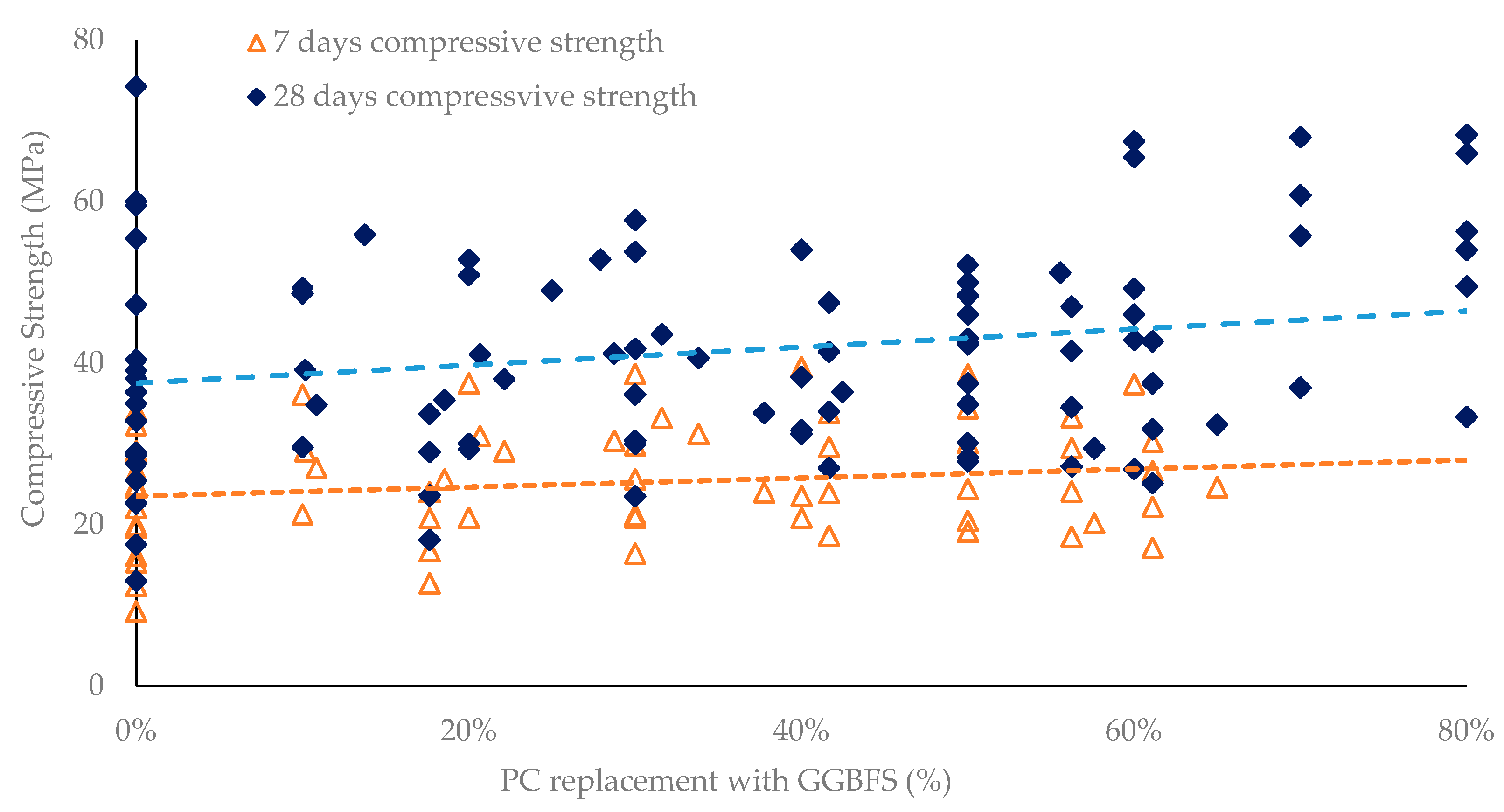
Granulated ground blast furnace slag (GGBFS) is a by-product of the iron production process. GGBFS is a commonly used SCM. EC of GGBFS is only 195 kg CO2e/t, which is only 21.5% of PC. GGBFS helps in decarbonization of concrete when PC is replaced with GGBFS. The replacement of PC with GGBFS typically results in greater long-term strengths, lower chloride ion permeability, reduced creep, increased sulfate attack and alkali silica reactivity (ASR) resistance, enhanced workability, less bleeding, lower heat of hydration, and increased steel corrosion resistance. Studies have indicated that replacement rates more than or equivalent to 40% PC may retard initial and final setting time by 38.5% and 33.8%, respectively [27,28,29]. Generally, the early age (1 to 3 days) compressive strengths of GGBFS mixes are lower than PC mixes. However, after 7 days, the compressive strength of GGBFS mixes surpasses the strength of PC mixes, and by 28 days, the strength of GGBFS mixes is equivalent to PC mixes [30,31,32]. The effect of the replacement of PC with GGBFS is a concrete mix on its compressive strength for a w/b ratio of 0.45 to 1.19 is presented in Figure 6.
Figure 6 presents the compressive strength of concrete with w/b ratios from 0.28 to 1.19, resulting in 28-day compressive strengths between 13 MPa and 74 MPa for various replacement levels of Portland cement with GGBFS. This is depicted by multiple compressive strength data points at various PC replacement levels (by GGBFS) corresponding to different w/b ratios. It is noted that some variation in compressive strength may also be due to variance in physical and chemical properties of GGBFS used by various researchers. This figure may be used for designing a fit-for-purpose GGBFS concrete.
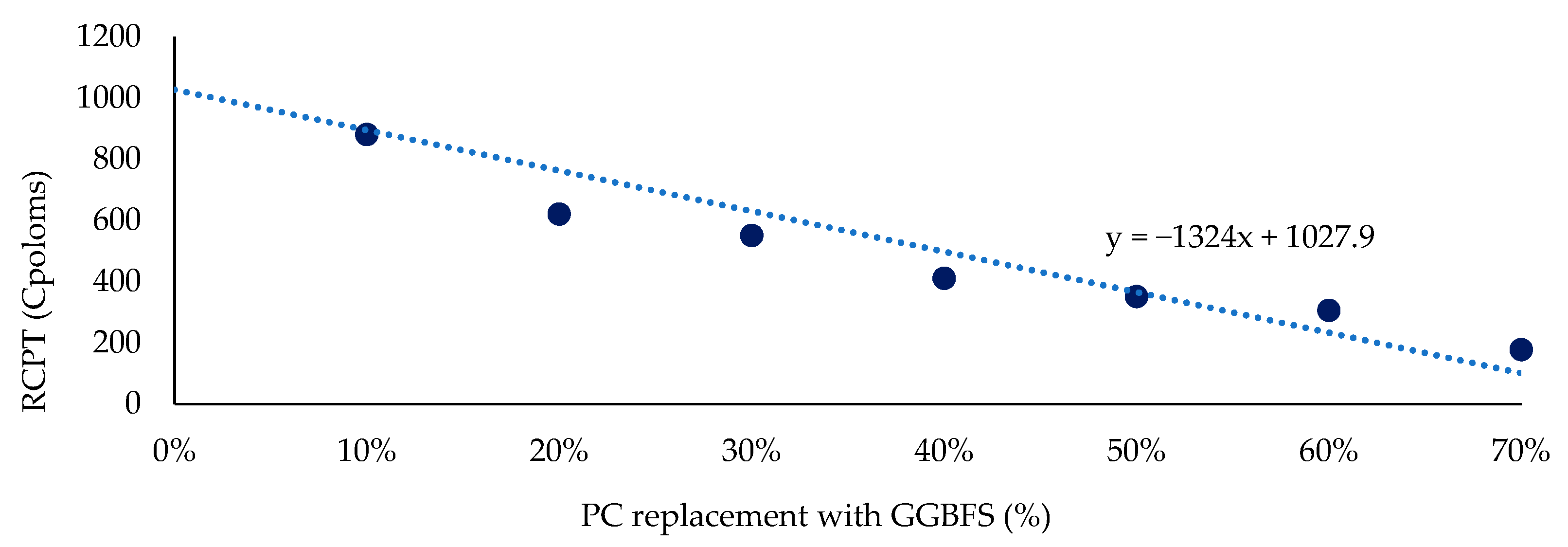
The permeability of mature concrete containing GGBFS in the binder is much lower than that of PC and PC + FA binder concretes. As the GGBFS content is increased, permeability of the concrete decreases because the pores in concrete that normally contain calcium hydroxide are, in part, filled with calcium silicate hydrates resulting from the hydration of the GGBFS cement [32,40]. The effect of replacing PC with GGBFS on the chloride resistance of concrete for 40 MPa is shown in Figure 7, which reveals that the chloride resistance of concrete improves with an increase in GGBFS in the concrete mix. It may be inferred from this figure that 50–70% PC replacement with GGBFS is effective in reducing the chloride ion penetrability to low levels in a concrete mix installed in an aggressive chloride environment.
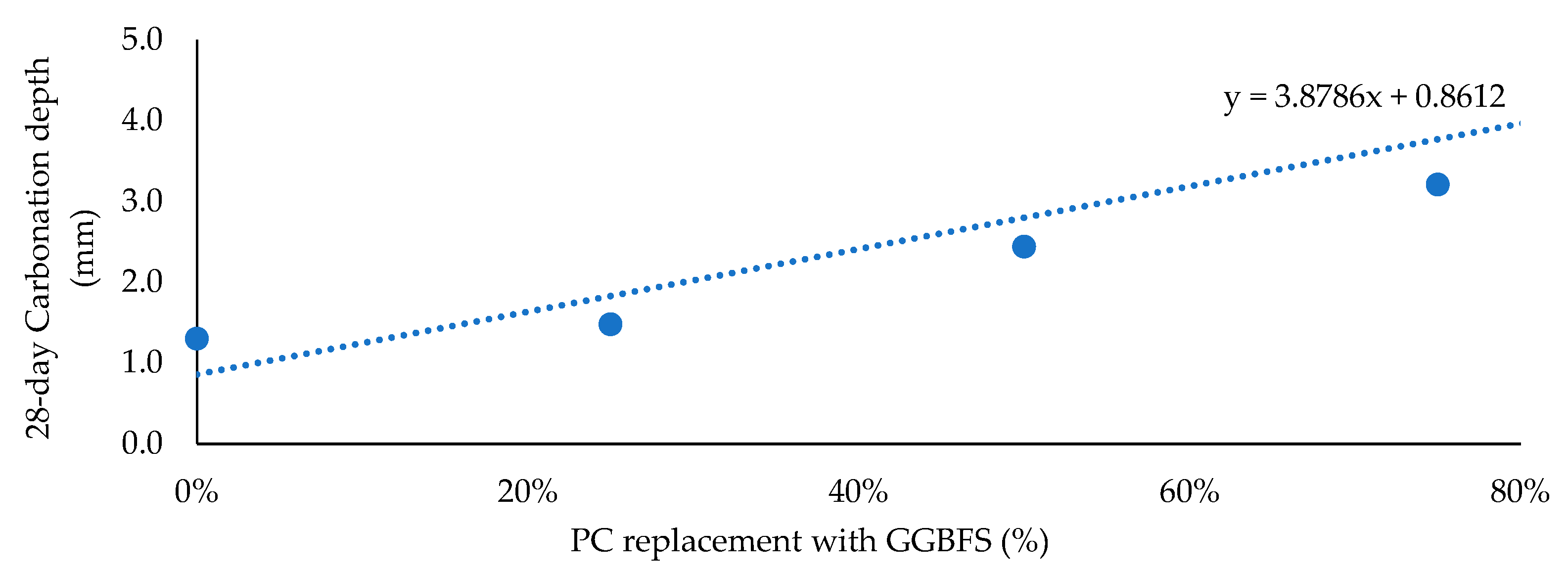
The carbonation resistance of concrete containing GGBFS is presented in Figure 8 which reveals that carbonation resistance reduces with increase in GGBFS content in the concrete mix. The reduced calcium and alkali contents lead to a lower buffering capacity in GGBFS blended cements, and polymerization shrinkage may lead to increased porosity. It is reported that at a replacement level ≥25%, the carbonation resistance is decreased compared to plain PC because all portlandite and C–A–S–H is not consumed during carbonation of GGBFS blended cements under moderately accelerated carbonation conditions (3–5 vol% CO2). However, at high GGBFS replacement levels, the degree of portlandite and C-A-S–H carbonation is higher compared to PC systems.

4.3. PC, FA, and GGBFS Ternary Blend Concrete

A combination of FA and GGBFS may be used to replace PC in the binder of the concrete. This makes it possible to take advantage of the beneficial properties of FA and GGBFS to enhance the mechanical and durability properties while maximizing the PC replacement, inter alia, minimizing the EC. Figure 9 shows a comparison of mechanical and durability properties of PC, FA, and GGBFS binary and ternary blends [42]. This figure shows that a ternary blend with a higher degree of replacement of PC may provide mechanical and durability properties comparable to binary blends. This information may be used for designing low-carbon concrete.

5. Methodology for Selection of a Fit-for-Purpose Low-Carbon Concrete (LCC) for Bridge Elements

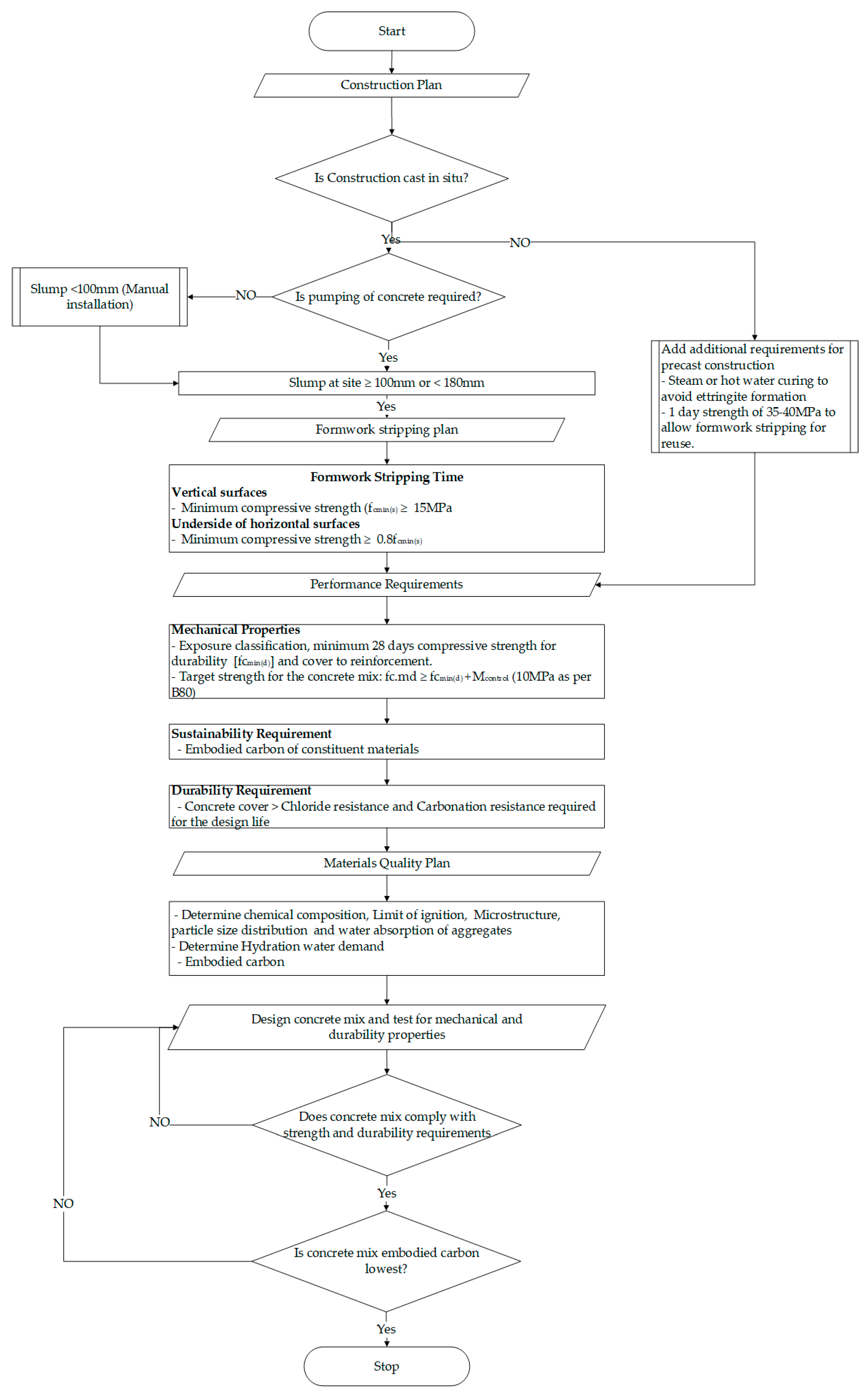
A conceptual process for the design and selection of an LCC is presented in Figure 10. This method may be used for designing or selecting a fit-for-purpose concrete mix complying with all prescriptive and performance requirements envisaged by Australian Standards and Transport Authorities specifications for bridges.
A concrete bridge comprises the following major elements, which may be constructed in situ or in a construction yard, transported to the site, and installed:
  • Substructure—Piles, pier, and headstock.
  • Superstructure—Bridge girders, decking and deck fittings, such as safety barriers, footpaths, kerbs, medians, etc.
The construction method adopted mainly depends on the location of the structure (on land or over water), accessibility of the construction site for supply and installation of formwork, and materials. The availability of crane capacity is also a key factor. Generally, cast-in situ (CIS) construction is adopted at sites with good access. However, precast construction methods are adopted when a pre-casting facility (well connected to the construction site), transporters, and cranes of required capacity are available. Sometimes a hybrid construction method consisting of a combination of precast and in situ construction is deployed. In this method, the bridge elements are constructed partially in the construction yard for installation and finishing off at the construction site. The bridge piers are generally spaced at 20 to 50 m. The CIS method is more efficient for substructure construction because it allows working simultaneously at multiple pier locations. This method also allows sharing of equipment, formwork, and crews between various pier locations for high productivity. The CIS method also enables continuous construction with the lowest number of joints, inter alia, a low-maintenance structure. The bridge deck is supported over headstocks of piers, which may be constructed in situ or with precast elements or a combination of CIS and Precast elements. For CIS construction, a comprehensive formwork installation followed by concreting and curing will be required. This would require an extended traffic closure. However, for precast decking, a series of precast girders spanning between pier headstocks is installed, followed by installation of an in situ decking. This method would require less site work and interruption to traffic.
It is assumed that only bridge girders will be precast, and other elements mentioned above will be cast-in situ (CIS). This is consistent with contemporary construction practice, where substructures are constructed in situ and superstructure is constructed as a combination of CIS and precast concrete. LCC selection strategy for each element is discussed here, considering that the example bridge is a road bridge located in exposure classification B2 (Refer Table 2), i.e., the bridge members are located in coastal areas (<50 km from coastline) and are exposed to chloride ingress and carbonation-led deterioration mechanism. The LCC selected will therefore have to demonstrate the mechanical strength and durability attributes required to achieve the service life of 100 years in this environment.
Table 2 reveals that for compliance with AS 5100.5, the concrete mix used shall have a minimum 28-day compressive strength of 40 MPa with binder content of 400 kg/m3, w/b of 0.45, and strength at removal of formwork of 28 MPa. However, the transport authority requirements given in Table 3 specify a minimum 28-day compressive strength of 40 MPa with a w/b of 0.32 and binder content of 370 kg/m3 for cast-in situ and 50 MPa with a w/b of 0.28 and binder content of 370 kg/m3 for precast concrete. The maximum chloride diffusion coefficient for cast-in situ and precast concrete is to be 3.5 × 10⁻¹² and 8.0 × 10⁻¹², respectively. Accordingly, concrete with a minimum 40 MPa and 50 MPa 28-day compressive strength has been proposed for CIS and precast construction.
An allowance of 10 MPa is provided over the minimum 28-day compressive strength for determining the target strength of the concrete mix to accommodate strength variations due to changes in climatic conditions and materials property variation (TfNSW-B80, 2020). This implies that the minimum target 28-day compressive strength for cast-in situ and precast concrete located in exposure condition B2 will be 50 MPa and 60 MPa, respectively. An inspection of Figure 3, Figure 6 and Figure 9 reveals that target 28-day compressive strength can be achieved by the concrete mixes with binary blends of PC and up to 70% FA or up to 80% GGBFS and ternary blends comprising 30% PC, 30% FA, and 40% GGBFS. It is noted that Figure 4 and Figure 7 show very low chloride permeability of these mixes, implying that these mixes are suitable for a bridge from a chloride durability perspective. However, Figure 9 reveals that addition of GGBFS provides better chloride resistance to concrete as compared to FA. It is noted that while determining the w/b ratio, the minimum water demand for hydration shall be calculated using the methodology reported by Srivastava et al., 2025 [43]. A binder content of 450 kg/m3 has been adopted for CIS concrete mixes.
For precast girders of the bridge, concrete with a minimum target strength of 60 MPa has been adopted. The concrete may have a binder content of up to 600 kg/m3 and will have to be subjected to heat-accelerated curing to achieve the required early strength. The accelerated heat-curing cycle will have to be designed to balance early strength development and durability. The concrete will have to be cured at a temperature and for a period to attain a maturity index not less than 350 °C·hours (refer to Table 2). The concrete temperature during the curing process will have to be maintained at <70 °C to avoid ettringite formation, which affects the durability (TfNSW-B80, 2020). It was reported by (French et al., 2023) [44] that for the economic feasibility of the precast girders production, the precasters are required to maintain a 24 h production cycle. The precast elements should gain 35–40 MPa compressive strength in 12–15 h to enable the transfer of prestress force. It was determined that a steam-cured high-workable concrete with 550 kg binder with 75% PC + 25% FA and w/b of 0.28, or 600 kg binder with 70% PC + 30% FA and w/b of 0.31, or 570 kg binder with 100% PC and w/b of 0.31 will be suitable for meeting the early strength requirement.
While selecting a suitable mix for a bridge element, its immediate environment needs to be considered. The bridge piles are embedded in the ground and, therefore, protected from atmospheric CO2 and behave as an infrastructure in a sheltered environment. Figure 5 shows that the carbonation rate of FA concrete in this zone will be higher than piers that will be exposed to the atmosphere. Also, piles, headstocks, and piers are exposed to chloride-infested environments, and therefore, the concrete mixes selected need to cater to both chloride and carbonation environments for durability. The bridge deck would comprise a CIS concrete deck over precast concrete girders. All bridge deck fittings mentioned above would be CIS concrete. It is noted that the cover to the reinforcement, in conjunction with the permeability of concrete (notionally represented by the compressive strength), is used as a defense against corrosion due to environmental factors.

6. Discussion

The potential composition of concrete mixes that may achieve 50 MPa and 60 MPa target 28-day compressive strength (with a minimum strength of 40 MPa and 50 MPa) is given in Table 8. EC of each concrete mix is also included in the table to enable selecting a low-carbon fit-for-purpose concrete mix. It may be seen that concrete mixes with 50% FA (EC = 208 kgCO2e/m3) and 70% GGBFS (EC = 184 kgCO2e/m3), and a ternary blend with 20% FA and 50% GGBFS with EC = 168 kgCO2e/m3 have the lowest EC in their respective category. It is noted that commercially available low-carbon concrete mixes such as Ecotera (50% to 65% GGBFS), Envisia (18% FA + 22% GGBFS or 50% GGBFS), etc., may also be used, if suppliers are able to provide test certificates from independent testing laboratories demonstrating compliance with envisaged mechanical strength and durability properties to comply with 100 years of design life. It is noted that these commercial mixes have been developed for use on building infrastructures, which are typically designed for a 50-year service life.
Considering that the bridge is in exposure zone B2, requiring both carbonation and chloride resistance, a ternary blend comprising 30% PC, 20% FA, and 50% GGBFS with EC = 168 kgCO2e/m3 appears to be the lowest carbon concrete solution. However, for a precast concrete, binary blend comprising 70% PC and 30% FA with EC = 384 kgCO2e/m3 is the lowest carbon concrete solution based on that reported in the literature (French et al., 2023) [44]. It is noted that early strength development requires high PC content and curing at elevated temperatures.
Generally, the substructure of a bridge consumes about 60% of the total concrete volume, and the superstructure requires about 40% concrete (15% in precast girders and 25% in decking and fitments). Considering this distribution, the EC per m3 of concrete works in the bridge is presented in Table 9, which shows that using fit-for-purpose LCC may reduce EC of a bridge structure by approximately 53%.

7. Conclusions

LCC involves the use of one or more SCMs in combination with PC. SCMs such as FA and GGBFS are sourced from waste stream materials, and their properties often vary with the source. It is therefore prudent to apply quality verification tests, including XRD, XRF, TGA, SEM, etc., to determine their chemical composition and microstructure. These tests will ensure consistency and compliance of materials with standards and specifications, resulting in good quality and consistent concrete for bridge construction. The test data may also be used for calculating the water demand. The strength and durability data sourced from the literature are useful in the preliminary design of LCC and in reducing the number of trials.
It is recommended that before commencing the concrete mix design, the performance requirements for the concrete shall be established to ensure compliance with relevant standards and specifications by following the processes outlined in Figure 1 and Figure 10. These processes, in conjunction with the performance requirements, should be used for determining all possible compliant binary and ternary concrete mixes for each element. The embodied carbon of all mixes is determined to select an LCC for each element. This process will ensure that the bridge structure, “as a whole”, will have the lowest embodied carbon while complying with mechanical and durability requirements.
The LCC selection process outlined in Figure 1 and Figure 10 may also be used for selecting fit-for-purpose concrete for infrastructures other than bridges, which may have different service lives (smaller or greater than 100 years) and may have to cater to a separate set of performance requirements.

Author Contributions

Conceptualization, methodology, data collection and analysis, data curation, and writing—original draft preparation, H.K.S.; writing—review and editing and supervision, V.V. and S.M.C. All authors have read and agreed to the published version of the manuscript.

Funding

This research received no external funding.

Data Availability Statement

No new data were created or analyzed in this study. The data used for analysis in this study has been sourced from the literature cited as references. Data sharing is not applicable to this article.

Conflicts of Interest

The authors declare no conflicts of interest.

Abbreviations

The following abbreviations are used in this manuscript:
PC (GP)Portland cement (general-purpose cement)
SCMSupplementary cementitious materials
FAFly ash
GGBFSGranulated ground blast furnace slag
DBSDelithiated beta spodumene
LCCLow-carbon concrete
ECEmbodied carbon
MPaMegapascal
kgKilogram
MtMillion tonnes
SEMScanning electron microscopy
XRFX-ray fluorescence
XRDX-ray diffraction
TGAThermogravimetric analysis
CISCast-in situ
RCPTRapid chloride permeability test
ATICAustralian Technical Infrastructure Committee
TfNSWTransport for New South Wales

References

  1. DoITRDCSA. National Sustainable Procurement in Infrastructure Guideline. 2025. Available online: https://www.infrastructure.gov.au (accessed on 14 September 2025).
  2. ITM. Embodied Carbon Measurement for Infrastructure Technical Guidance. 2024. Available online: https://www.infrastructure.gov.au (accessed on 14 September 2025).
  3. Vdz. Decarbonisation Pathways for the Australian Cement and Concrete Sector. 2021. Available online: https://www.ccaa.com.au (accessed on 30 July 2022).
  4. Vasikova, I.; Srivastava, H.; Nairn, J. Review of the embodied carbon of Australian concreting materials. In Proceedings of the Concrete 2023, Perth, Australia, 10–13 September 2023. [Google Scholar]
  5. ATIC. ATIC Spec 43. 2019. Available online: https://www.atic.net.au/wp-content/uploads/2021/01/ATIC-SP43-11July2019.pdf (accessed on 25 February 2024).
  6. Hanson. ECOTERA High Performance/ Low Carbon Concrete. 2023. Available online: https://epd-australasia.com/wp-content/uploads/2023/11/SP10206-Hanson-EPD-Ecotera-Sydney_Nov23.pdf (accessed on 26 February 2024).
  7. Boral. Boral—Pre-mix concrete EPD. 2023. Available online: https://www.boral.com.au/ (accessed on 25 February 2024).
  8. AS 5100.2:2017 Bridge Design (Part 2: Design Loads). Standards Australia. 2017. Available online: www.standards.org.au (accessed on 20 July 2025).
  9. TfNSW-B80. TfNSW QA Specification B80—Concrete Work for Bridges. 2020. Available online: www.transport.nsw.gov.au (accessed on 11 October 2025).
  10. MTRS70. Transport and Main Roads Specifications—MRTS70 Concrete. 2022. Available online: https://www.tmr.qld.gov.au/ (accessed on 21 June 2025).
  11. AS1141.60.1-2014: Potential Alkali-Silica Reactivity—Accelerated Mortar Bar Method. Standards Australia. 2014. Available online: www.standards.org.au (accessed on 10 October 2025).
  12. AS 3582.1—Supplementary Cementitious for Use with Portland and blended Cement 1: Fly Ash. Available online: www.standards.org.au (accessed on 11 October 2025).
  13. AS 3582.2—Supplementary Cementitious Materials, Part 2: Slag -Ground Granulated Blast Furnace. 2016. Available online: www.standards.org.au (accessed on 21 June 2025).
  14. AS 5100.5: 2017 Bridge Design (Part-5 Concrete). Standards Australia. 2017. Available online: www.standards.org.au (accessed on 20 July 2025).
  15. AS 3582.4—Supplementary Cementitious Materials, Part 4: Pozzolans—Manufactured. Standards Australia. 2022. Available online: www.standards.org.au (accessed on 11 October 2025).
  16. AusLCI. Construction_Emission_Factor_List_AusLCI1_38_v1. 2022. Available online: https://www.alcas.asn.au/auslci-emissions-factors (accessed on 23 September 2022).
  17. Circular Ecology. ICE DB Educational V4.0—Dec 2024. 2024. Available online: https://circularecology.com (accessed on 4 May 2025).
  18. Nath, P.; Sarker, P. Effect of fly ash on the durability properties of high strength concrete. Procedia Eng. 2011, 14, 1149–1156. [Google Scholar] [CrossRef]
  19. Atis, C.D. High-Volume Fly Ash Concrete with High Strength and Low Drying Shrinkage. J. Mater. Civ. Eng. 2003, 15, 153–156. [Google Scholar] [CrossRef]
  20. Burden, D. The Durability of Concrete Containing High Levels of Fly Ash—PCA R&D Serial No. 2989. 2006. Available online: https://d1wqtxts1xzle7.cloudfront.net/34756918/durability_flyash1-libre.pdf (accessed on 20 October 2024).
  21. Bouzoubaa, N.; Bilodeau, A.; Sivasundaram, V.; Chakraborty, A.K. Mechanical properties and durability characteristics of high-volume fly ash concrete made with ordinary Portland cement and blended Portland fly ash cement. Spec. Publ. 2006, 242, 303–320. [Google Scholar]
  22. Kumar, B.; Tike, G.K.; Nanda, P.K. Evaluation of Properties of High-Volume Fly-Ash Concrete for Pavements. J. Mater. Civ. Eng. 2007, 19, 906–911. [Google Scholar] [CrossRef]
  23. Huang, C.-H.; Lin, S.-K.; Chang, C.-S.; Chen, H.-J. Mix proportions and mechanical properties of concrete containing very high-volume of Class F fly ash. Constr Build Mater 2013, 46, 71–78. [Google Scholar] [CrossRef]
  24. Alaka, H.A.; Oyedele, L.O. High volume fly ash concrete: The practical impact of using superabundant dose of high range water reducer. J. Build. Eng. 2016, 8, 81–90. [Google Scholar] [CrossRef]
  25. von Greve-Dierfeld, S.; Lothenbach, B.; Vollpracht, A.; Wu, B.; Huet, B.; Andrade, C.; Medina, C.; Thiel, C.; Gruyaert, E.; Vanoutrive, H.; et al. Understanding the carbonation of concrete with supplementary cementitious materials: A critical review by RILEM TC 281-CCC. Mater. Struct. Mater. Constr. 2020, 53, 136. [Google Scholar] [CrossRef]
  26. Huy Vu, Q.; Pham, G.; Chonier, A.; Brouard, E.; Rathnarajan, S.; Pillai, R.; Gettu, R.; Santhanam, M.; Aguayo, F.; Folliard, K.J.; et al. Impact of different climates on the resistance of concrete to natural carbonation. Constr. Build. Mater. 2019, 216, 450–467. [Google Scholar] [CrossRef]
  27. Borges, P.H.R.; Costa, J.O.; Milestone, N.B.; Lynsdale, C.J.; Streatfield, R.E. Carbonation of CH and C-S-H in composite cement pastes containing high amounts of BFS. Cem. Concr. Res. 2010, 40, 284–292. [Google Scholar] [CrossRef]
  28. Hussain, F.; Kaur, I.; Hussain, A. Reviewing the influence of GGBFS on concrete properties. Mater. Today Proc. 2020, 32, 997–1004. [Google Scholar] [CrossRef]
  29. Richardson, D.N. Scholars’ Mine Scholars’ Mine Strength and Durability Characteristics of a 70% Ground Strength and Durability Characteristics of a 70% Ground Granulated Blast Furnace Slag (GGBFS) Concrete Mix Granulated Blast Furnace Slag (GGBFS) Concrete Mix. 2006. Available online: https://scholarsmine.mst.edu/civarc_enveng_facwork (accessed on 20 October 2024).
  30. CCAA. 2018-CCAA TECH_NOTE_78_-_Ground_Slag. 2018. Available online: https://www.ccaa.com.au (accessed on 20 October 2024).
  31. Megat Johari, M.A.; Brooks, J.J.; Kabir, S.; Rivard, P. Influence of supplementary cementitious materials on engineering properties of high strength concrete. Constr. Build. Mater. 2011, 25, 2639–2648. [Google Scholar] [CrossRef]
  32. ACI Committee 233. ACI 233R-17—Guide to the Use of Slag Cement in Concrete and Mortar. American Concrete Institute. 2017. Available online: http://concrete.org/Publications. (accessed on 20 October 2024).
  33. Oner, A.; Akyuz, S. An experimental study on optimum usage of GGBS for the compressive strength of concrete. Cem. Concr. Compos. 2007, 29, 505–514. [Google Scholar] [CrossRef]
  34. Majhi, R.K.; Nayak, A.N. Bond, durability and microstructural characteristics of ground granulated blast furnace slag based recycled aggregate concrete. Constr. Build. Mater. 2019, 212, 578–595. [Google Scholar] [CrossRef]
  35. Topçu, I.B.; Boĝa, A.R. Effect of ground granulate blast-furnace slag on corrosion performance of steel embedded in concrete. Mater. Des. 2010, 31, 3358–3365. [Google Scholar] [CrossRef]
  36. Elchalakani, M.; Aly, T.; Abu-Aisheh, E. Sustainable concrete with high volume GGBFS to build Masdar City in the UAE. Case Stud. Constr. Mater. 2014, 1, 10–24. [Google Scholar] [CrossRef]
  37. Ganesh, P.; Murthy, A.R. Tensile behaviour and durability aspects of sustainable ultra-high performance concrete incorporated with GGBS as cementitious material. Constr. Build. Mater. 2019, 197, 667–680. [Google Scholar] [CrossRef]
  38. Özbay, E.; Erdemir, M.; Durmuş, H.I. Utilization and efficiency of ground granulated blast furnace slag on concrete properties—A review. In Construction and Building Materials; Elsevier: Amsterdam, The Netherlands, 2016; Volume 105, pp. 423–434. [Google Scholar] [CrossRef]
  39. Kanavaris, F.; Gibbons, O.; Walport, E.; Shearer, E.; Abbas, A.; Orr, J.; Marsh, B. Reducing the embodied carbon of lightweight aggregate concrete for structural applications. Proc. Inst. Civ. Eng. Eng. Sustain. 2021, 175, 75–83. [Google Scholar] [CrossRef]
  40. Hooton, R.D. Canadian use of ground granulated blast-furnace slag as a supplementary cementing material for enhanced performance of concrete. Can. J. Civ. Eng. 2000, 27, 754–760. [Google Scholar] [CrossRef]
  41. Bhat, A.V.; Tengli, S.K. Behaviour of ground granulated blast furnace slag concrete in marine environment under chloride attack. Int. J. Innov. Technol. Explor. Eng. 2019, 9, 1659–1664. [Google Scholar] [CrossRef]
  42. Huyen Vu, T.; Yang, Y.; Cao, T.; Srivastava, H.; Sirivivatnanon, V. Machine Learning-Based Prediction of Chloride Resistance in Low-Carbon Concretes Using Experimental Data. In Proceedings of the Concrete 2025 Proceeding, Adelaide, Australia, 7–10 September 2025. [Google Scholar]
  43. Srivastava, H.K.; Sathorn, S.; Vimonsatit, V.; Clark, S. A Systematic Approach for Optimising Water to Binder Ratio for Low Carbon Concrete. In Proceedings of the ISEC 2025 Proceeding, Seoul, Republic of Korea, 26–27 August 2025; Volume 12. [Google Scholar] [CrossRef]
  44. French, D.; Chaves, I.; Smith, G.; Borgert, J. Optimizing Prestressed Concrete Mix designs for Lower Carbon Emissions. In Proceedings of the Concrete 2023 Proceeding, Perth, Australia, 10–13 September 2023. [Google Scholar]
Figure 1. Process for establishing performance criteria for LCC.
Infrastructures 10 00274 g001
Figure 2. Effect of replacing Portland cement with fly ash and GGBFS in concrete on embodied carbon.
Infrastructures 10 00274 g002
Figure 3. Effect of replacement of Portland cement with fly ash in concrete on compressive strength. (Source: Data extracted from references [18,19,20,21,22,23,24]).
Infrastructures 10 00274 g003
Figure 4. Chloride resistance (RCPT test results) of FA concrete (Source: Data extracted from reference [18,20]).
Infrastructures 10 00274 g004
Figure 5. Carbonation resistance of FA concrete (Source: Data extracted from [26]).
Infrastructures 10 00274 g005
Figure 6. Effect of replacement of Portland cement with GGBFS in concrete on compressive strength. (Source: Data extracted from references [29,31,33,34,35,36,37,38,39]).
Infrastructures 10 00274 g006
Figure 7. Chloride resistance (RCPT test results) of M40-grade GGBFS concrete (Source: Data extracted from [41]).
Infrastructures 10 00274 g007
Figure 8. Effect of PC replacement on carbonation depth for 28-day cured concrete (Source: Data extracted from reference [25]).
Infrastructures 10 00274 g008
Figure 9. Comparison of mechanical and durability properties of PC, FA, and GGBFS binary and ternary blends (Source: Data extracted from [42]).
Infrastructures 10 00274 g009
Figure 10. Proposed process for designing a fit-for-purpose LCC.
Infrastructures 10 00274 g010
Table 1. Exposure classifications in Australia (AS 5100.5).
Exposure ClassificationSurface and Exposure Environment
A
  • Surface of members in contact with the ground and protected by a damp-proof membrane in non-aggressive soils
  • Surfaces of members in interior environments.
  • Surfaces of members in above-ground exterior environments in areas that are inland (>50 km from coastline) and in non-industrial arid or temperate zones.
  • Surface of members in soft water
  • Surface of members in an environment other than A, B1, B2, C1, and C2.
B1
  • Surfaces of members in contact with ground comprising non-aggressive soils.
  • Surfaces of members above ground in exterior environments in areas that are inland (>50 km from coastline) or in a non-industrial zone located in a temperate or tropical zone or in an industrial zone in any climatic zone.
  • Surfaces of members in above-ground exterior environments in areas located near the coast (1 km to 50 km from the coastline).
  • Surfaces of members located in fresh water with chloride content up to 1000 ppm.
B2
  • Surfaces of members in coastal areas (<50 km from coastline) in any client zone or in brackish water (chloride content 1000–6000 ppm) or permanently submerged in sea or brackish water (chloride content > 6000 ppm) members.
C1
  • Surfaces of members in sea water spray zone.
C2
  • Surfaces of members in the tidal or sea water splash zone.
Table 2. Minimum requirements for concrete mixes (AS 5100.5).
Exp.fcmin
(MPa)
Binder
(PC + SCM) (kg/m3)
W/Bfc at Completion of Curing (MPa)Water Curing Duration (Days)Heat Curing Period (°C·Hours)
A25280-17.53As required
B1323300.5022.47350
B2404000.4528.07350
C1504200.4028.014420
C2504200.3635.014420
Table 3. Minimum requirements for concrete mixes (TfNSW-B80, 2020).
Exp.fcmin,d (MPa)Bmin (kg/m3)W/BDmax (m2/s)
CIPPCIPPCIPPNT 443NT 443
A2532320 3200.400.28N/AN/A
B132403203200.400.28N/AN/A
B240503703700.320.283.5 × 10−128.0 × 10⁻¹²
C150604204200.320.282.0 × 10−124.0 × 10⁻¹²
C255604204200.320.282.0 × 10−124.0 × 10⁻¹²
Dmax = maximum chloride ingress coefficients; NT 443 and NT492 = Nordtest NT Build tests; CIP = cast-in-place concrete; P = precast concrete; N/A = not applicable.
Table 4. SCM limits in concrete mixes (AS 5100.5).
SCM Limits
Concrete MixFAGGBFSSF
Binary blends25–40%30–70%4–10%
Ternary blends25–30%20–35%-
25–35%-4–10%
-50–65%4–10%
Table 5. Required cover for standard formwork and compaction.
Exposure ClassificationRequired Cover (mm) and Characteristic Strength (MPa)
25 MPa32 MPa40 MPa≥50 MPa
A45353030
B1 504540
B2 6050
C1 70
C2 80
Table 6. Embodied carbon of concrete constituents.
Concrete ConstituentsEmbodied Carbon
(kg CO2e/kg)
Source
General (Portland) purpose (GP) cement0.905AusLCI database [16]
Fly ash (FA)0.020AusLCI database
Granulated ground blast furnace slag (GGBFS)0.195AusLCI database
Silica fume (Amorphous Silica)0.014AusLCI database
Fine aggregate0.004AusLCI database
Coarse aggregate0.011AusLCI database
Tap water, at user, Australia0.00045AusLCI database
Plasticizer and superplasticizers1.88ICE database [17]
Table 7. Chloride ion penetrability based on charge passed.
Charge Passed (Coulombs)Chloride Ion Penetrability
>4000High
2000–4000Moderate
1000–2000Low
100–1000Very low
<100Negligible
Source: Reference [20].
Table 8. Potential low-carbon concrete mixes along with embodied carbon.
Target Strength (MPa)Concrete MixBinder ContentECCuring
PCFAGGBFS(kg/m3)(kg CO2e/m3)
CIS
50–28 days
100%--450407Water curing
60%40%-450248
50%50%-450208
40%-60%450216
30%-70%450184
30%20%50%450168
30%30%40%450169
Precast
60–28 days
35–1 day
100%--570516Heat-accelerated curing
75%25%-600410
70%30%-600384
Table 9. Embodied carbon of bridge structure per m3.
Bridge ComponentConcrete QuantityEmbodied Carbon (kgCO2e/m3)Bridge Structure Embodied Carbon (kgCO2e/m3)
m3PCCLCCPCCLCCChange
Superstructure—CIS (40 MPa) concrete @ 25%0.2540716810242−60
Superstructure—precast (50 MPa) concrete @ 15%0.155163847758−20
Substructure (40 MPa) concrete @ 60%0.60407168244101−143
423200−223
Disclaimer/Publisher’s Note: The statements, opinions and data contained in all publications are solely those of the individual author(s) and contributor(s) and not of MDPI and/or the editor(s). MDPI and/or the editor(s) disclaim responsibility for any injury to people or property resulting from any ideas, methods, instructions or products referred to in the content.