Abstract
This study investigates the mechanical performance of two prosthetic forelimb designs for dogs—one with a solid structure and the other with a perforated structure—using Finite Element Analysis (FEA). Both models were analyzed under static loading conditions representing approximately 60% of a dog’s body weight, the typical load borne by the forelimbs. The prosthetics were modeled with ABS plastic, a widely used 3D printing material, and evaluated for Von Mises stress, total deformation, elastic strain, and factor of safety. The analysis showed that both models remained within the elastic limit of the material, indicating that no permanent deformation would occur under the applied loads. The Solid Model demonstrated a significantly higher factor of safety (14) and lower deformation, confirming its structural strength but also highlighting excessive rigidity, increased material use, and higher cost. In contrast, the Perforated Model exhibited slightly higher localized stresses and a lower factor of safety (3.01), yet it still met essential safety requirements while providing greater compliance, flexibility, and material efficiency. These attributes are desirable for comfort, adaptability, and practicality in veterinary applications. Although its long-term durability requires further evaluation, the Perforated Model strikes a more effective balance between safety, comfort, and sustainability. Based on these findings, the perforated design is considered the more suitable option for canine prosthetic development. Future work will extend the analysis to dynamic loading scenarios, such as walking and running, to better simulate real-world performance.
1. Introduction
Additive manufacturing, or 3D printing, is a process that builds parts layer by layer based on a digital design. This approach is different from traditional methods like machining, which remove material from a solid block to shape a part. One of the key advantages of additive manufacturing is its ability to create complex shapes and internal features that would be difficult—or even impossible—to produce with conventional techniques. Because of this, it is being used more and more in fields like aerospace, where lightweight and high-strength parts are important, and in healthcare, where custom implants and prosthetics can be made to fit individual patients. It is also valuable in the automotive industry for making prototypes quickly and producing parts that need to meet specific performance requirements. Beyond that, it is starting to play a role in renewable energy systems by helping develop components for wind turbines and other equipment. The flexibility and efficiency of additive manufacturing make it a practical and increasingly important tool across many industries [1,2,3].
Computational design and additive manufacturing have come together in a practical and impactful way to support the advancement of prosthetic devices for both humans and animals. For example, Rahman et al. [4] conducted a finite element analysis (FEA) to evaluate and enhance the performance of prosthetic running blades by exploring alternative composite materials. Using ANSYS (2024R2), they created mechanical models of existing Ossur blade designs and simulated how different materials would impact structural behavior. The study considered two composite materials—polyethylene epoxy and vinylester—as potential replacements for the materials traditionally used in the blades. The results showed that substituting the original materials with these alternatives significantly reduced strain in all three blade designs examined: the Cheetah Blade, Flex-Run Blade, and Flex-Sprint Blade. Specifically, the Cheetah Blade’s maximum principal strain decreased from 0.00299 in/in to 0.0026184 in/in—a 12.4% reduction. The Flex-Run and Flex-Sprint blades also showed strain reductions of 11.5% and 12.9%, respectively. These improvements were attributed to the higher Young’s modulus of the new materials. Ismail et al. [5] carried out a study focused on designing and developing a below-knee prosthetic leg specifically intended for running. The goal was to create a strong, lightweight, comfortable, and flexible prosthesis that would be more affordable than imported alternatives. To identify the most effective design, the researchers explored six different geometric shapes and three installation concepts using SolidWorks 2024. They applied the finite element method to analyze each design under a static load equivalent to eight times the user’s body weight (up to 80 kg). The simulated prosthetic leg was made from carbon fiber composite, which has a tensile strength of 538.83 MPa, a Young’s modulus of 76,975.71 MPa, and a Poisson’s ratio of 0.14. Among the tested options, the design with 10 mm thickness performed the best, showing a maximum von Mises stress of 414.76 MPa and a safety factor of 1.29. Based on their decision matrix, the most favorable outcome was found in the second installation concept paired with the third geometric design, which received the highest evaluation score of 80.
In veterinary medicine, prosthetic limbs present a promising alternative to traditional approaches like euthanasia or full limb amputation when addressing limb deformities or injuries. Studies by Mich [6] and Carr et al. [7] have shown that animal prosthetics can enhance mobility, prevent joint deterioration, and improve overall quality of life. However, challenges such as skin irritation and mechanical failure of the devices still persist. The final outcome is often influenced by factors such as the level of limb loss and the specific type of prosthetic used [8]. With the emergence of more cost-effective production methods like 3D printing, prosthetic solutions for animals are becoming increasingly accessible [9]. With the growth of additive manufacturing, there has been significant improvement on the design and efficacy of human prosthetics to tackle the problem of limb amputation. Partial limb amputation has become the standard for human patients so that the technology of prosthesis may be used; contrarily, when it comes to animals, total limb amputation has become the standard [10]. It is either this or euthanizing the animal [11].
There is limited research into the design and analysis of prosthetic models for animals as such, this study aims to encourage the use of prosthesis with animals, more specifically, with canines by using additive manufacturing to model different 3D-printed canine prosthetics. It is required that the prosthetic models should be functionally consistent with supporting body weight, provide shock absorption, and flexibility, etc. [11]. There are two types of limb prosthesis for canines: Endo-Exo Prosthesis and Exo-prosthesis [11]. Endo-Prosthesis incorporates the prosthesis into the remaining bone through a process known as osseointegration [12]. This implementation is not very common. Conversely, exo-prosthetics are more conventional and they use external sockets and suspension systems [13]. The models used in this study are exo-prosthetics. The mechanical behavior of the designed models was evaluated using Finite Element Method (FEM). FEM is a powerful computational technique for solving differential and integral equations in various fields of engineering and applied sciences. Regarding this study, this method solves and helps visualize stress, deformation and strain in two different models namely perforated and solid models. To simplify the analysis, the scope of this study was limited to static loading conditions.
2. Materials and Methods
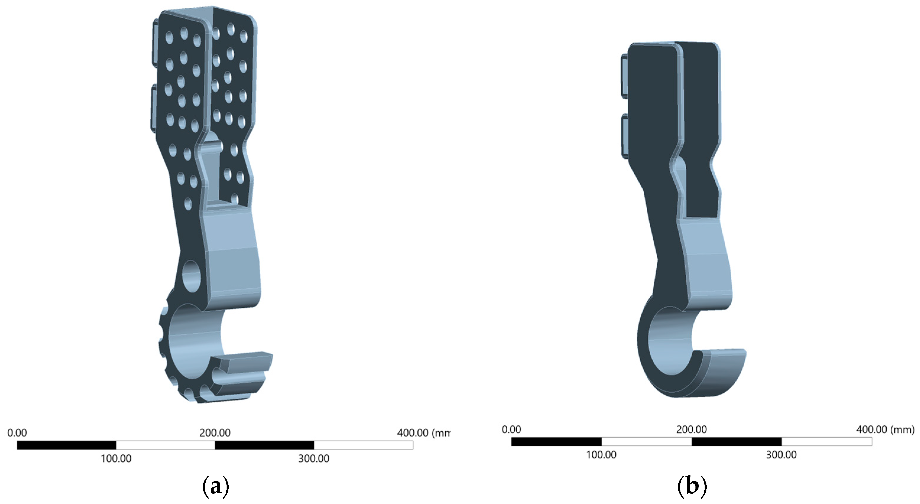
This research compares two 3D-printed dog forelimb prosthetic models: one with perforations at the socket and grooves at the bottom (labeled as Perforated Model) and one completely solid model (labeled as Solid Model) shown in Figure 1. The reason for this comparison is because the perforated and solid prosthetic designs represent two widely considered approaches in the literature, each with distinct mechanical and biological implications. Solid designs are typically favored for their higher structural rigidity, while perforated designs are of interest for their potential to reduce weight, improve fixation, and facilitate tissue integration. However, direct comparisons of these two approaches remain limited, particularly in terms of quantifying their mechanical performance under realistic loading conditions. By addressing this gap, our study provides a clearer rationale for investigating both designs and highlights the importance of understanding their trade-offs for clinical decision-making. The 3D model of the prosthetics was generated using a Computer Aided Design (CAD) software, more specifically, Dassault Systèmes’ SOLIDWORKS 2024 software. Various tools and features were used to build the two 3D models. These features include bossed-based extrusion to build the material, extrude cuts to remove material, fillets to round sharp edges and improve strength, patterns and mirroring. High impact Acrylonitrile Butadiene Styrene (ABS) plastic was used as the material for testing. Table 1 shows the material properties of the high impact ABS plastic used for the study while conducting Finite Element Analysis (FEA). ABS was chosen because it is one of the most widely used thermoplastic polymers in additive manufacturing, offering a favorable balance of strength, toughness, and ease of processing. Its mechanical properties (e.g., tensile strength and impact resistance) make it suitable for replicating the structural behavior of prosthetic components under load in an experimental or prototyping context. Furthermore, ABS is cost-effective, readily available, and compatible with standard 3D printing systems, which allows for efficient iteration of design modifications during the research phase. While not intended as the final clinical material, ABS provides a reliable and practical medium for evaluating mechanical performance and validating design concepts prior to transitioning to advanced biocompatible materials. ABS is occasionally used in the fabrication of prosthetic components, particularly in applications where cost-effectiveness, ease of manufacturing, and lightweight properties are prioritized. While not suitable for high-load or permanent prosthetic parts, ABS can be effectively utilized in non-load-bearing elements such as cosmetic covers, temporary sockets, or early-stage prototypes [14]. Its compatibility with 3D printing makes it an attractive material for rapid prototyping and low-resource environments, where design iterations and functional testing can be conducted before transitioning to more durable materials like carbon fiber composites or titanium. However, due to its limited mechanical strength, fatigue resistance, and long-term durability, ABS is typically reserved for applications that do not require high structural performance.
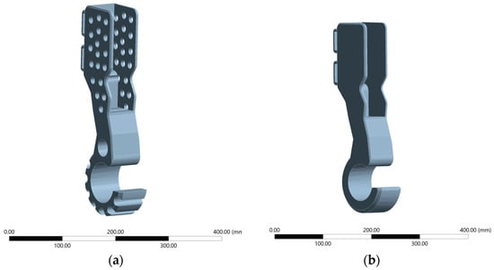
Figure 1.
(a) Perforated Model; (b) Solid Model.

Table 1.
Mechanical Properties of high-impact ABS used for FEA.
Due to the stark difference in designs, the Perforated Model weighs 1.99 lbs while the Solid Model weighs 2.40 lbs.
To ensure consistency in the research, both models were evaluated using Finite Element Analysis (FEA) within the ANSYS Static Structural (ANSYS Mechanical) environment. The analysis involved simulating a standing dog using only one prosthetic (meaning the dog only had one amputation on one of its forelimbs). The analysis also involved studying different weight classes of dogs classified as Light, Medium, Large and Extra-large on both models. These different weight classifications [15] provided the various loads tested on both models. The load was calculated by multiplying the weight of the dog by 0.3, as dogs bear about 60% of their body weight on their forelimbs [16].
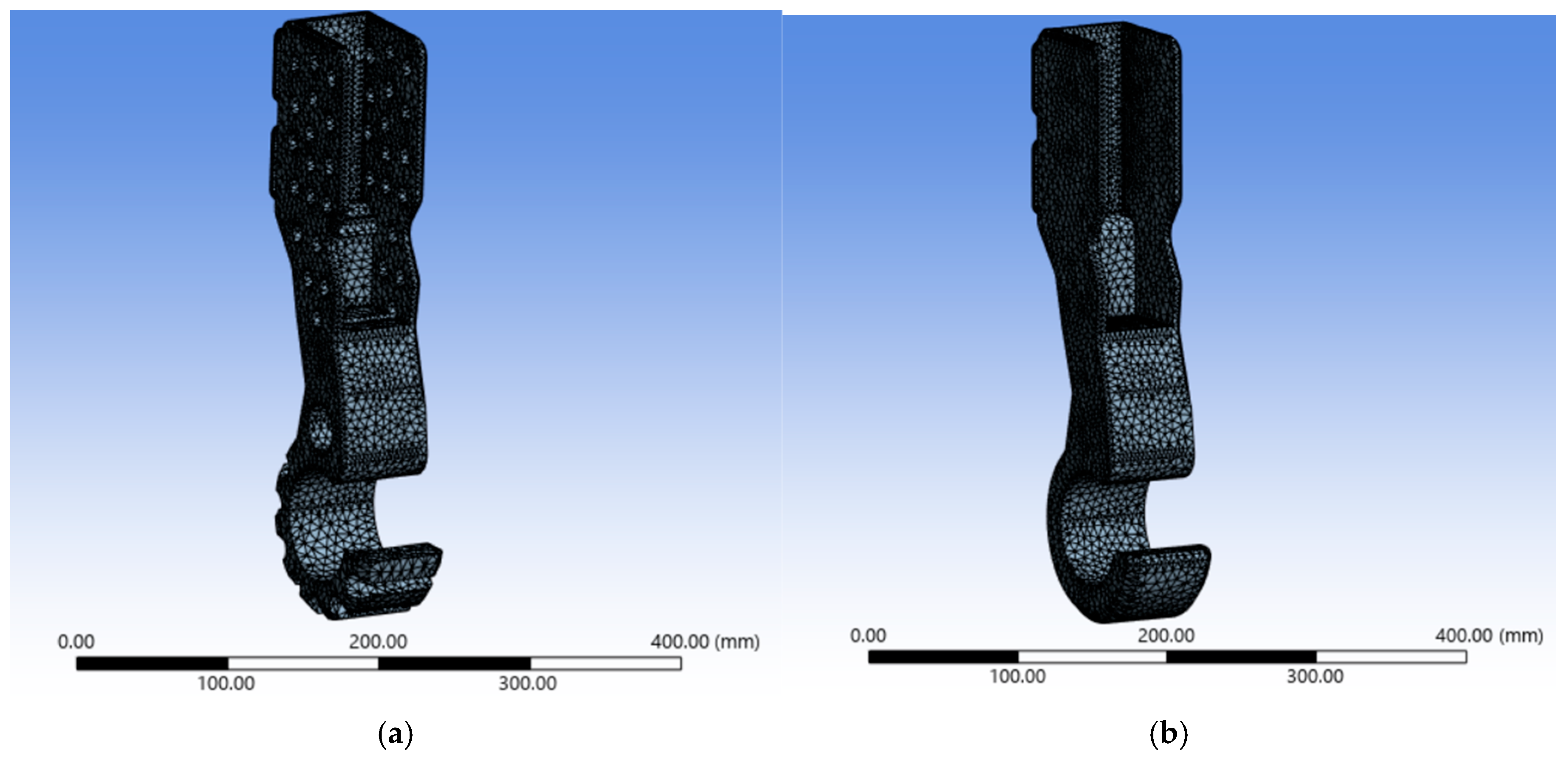
Another measure taken to ensure accuracy was verifying that the analysis model in ANSYS Mechanical achieved mesh independence. Various element sizes were tested in the preliminary stages of the research until convergence was reached and there were no discrepancies in the results to ensure the simulation was not mesh dependent on both models. An element size of 1 mm was used for the perforated model to create a fine mesh with a quad dominant sheet body method yielding the following mesh statistics: 53,010 nodes, 28,744 elements, 8675 corner nodes and 44,353 mid nodes. Similarly, the same element size of 1 mm was used for the solid model to create a fine mesh with a quad dominant sheet body method which yielded the following mesh statistics: 47,362 nodes, 26,354 elements, 7572 corner nodes and 39,790 mid nodes. Figure 2 shows a visual representation of the mesh of both models. The perforated model required at least 28,744 elements to achieve mesh independence while the solid model required at least 26,354 elements to achieve convergence.
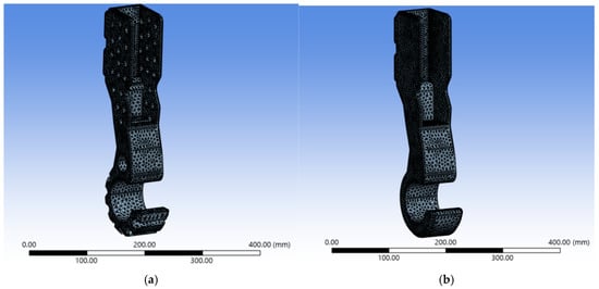
Figure 2.
(a) Perforated Model Mesh; (b) Solid Model Mesh.
Mesh Convergence Verification:
In the preliminary phase of the research, various mesh element sizes were tested in the same conditions (e.g., same loading, boundary conditions) to ensure the FEA model obtained mesh independence. The following element sizes were tested: 20 mm, 10 mm, 5 mm, and 1 mm. Below is an example of testing for mesh convergence of the perforated model with a load of 203.07 N (Table 2). An element size of 1 mm was determined to be sufficient for achieving grid-independent results. Further refinement to 0.5 mm produced a relative error of less than 4%.

Table 2.
Mesh Convergence.
Boundary Conditions:
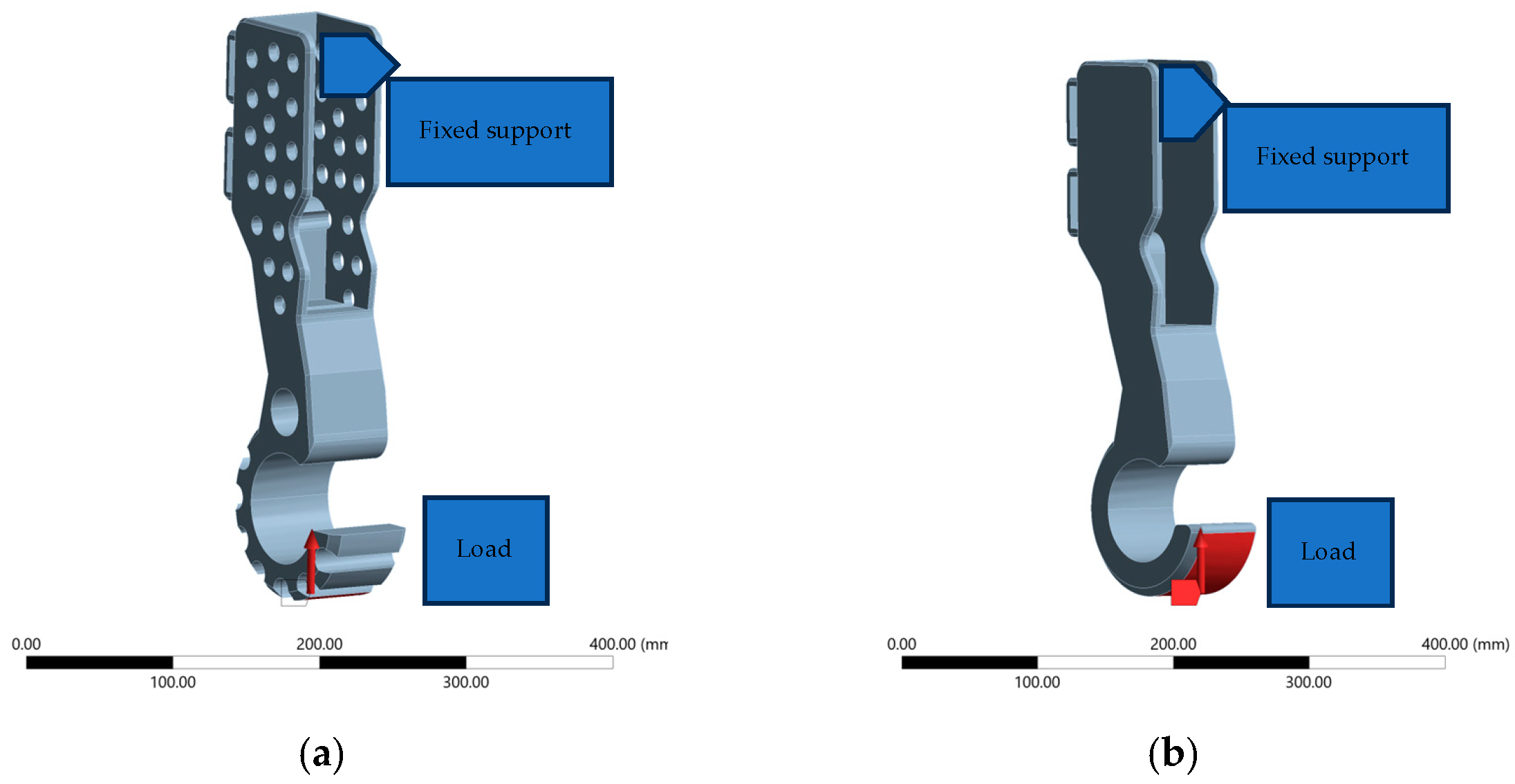
The same boundary conditions were used on both models. A fixed support was applied on the inside of the socket of both models, and the load was applied on the point of the footpad which contacted the ground as shown in Figure 3. In a load-bearing static problem such as a dog standing, the load applied by the dog’s leg is equal in magnitude to the Ground Reaction Force (GRF) due to the principle of static equilibrium; hence, why the load was placed at the bottom of the footpad.
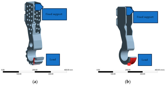
Figure 3.
(a) Perforated Model Boundary Conditions; (b) Solid Model Boundary Conditions.
Lastly, the following results were then solved and studied: Equivalent Stress (Von Mises Stress) in MPa, Total Deformation in mm, and Equivalent Strain in mm/mm. The units were the same for both models. Since the research was solely simulation based, no dogs or animals were tested on.
3. Results
3.1. Data Used
Table 3 below shows different dog breeds and their mass in kilograms categorized by their masses:

Table 3.
Data used for running the simulation.
3.2. Data Obtained for the Perforated Model
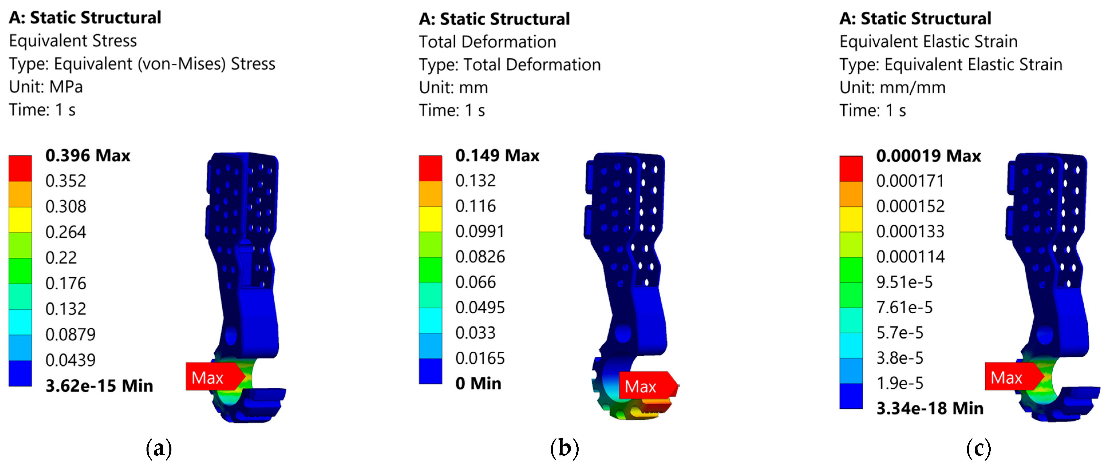
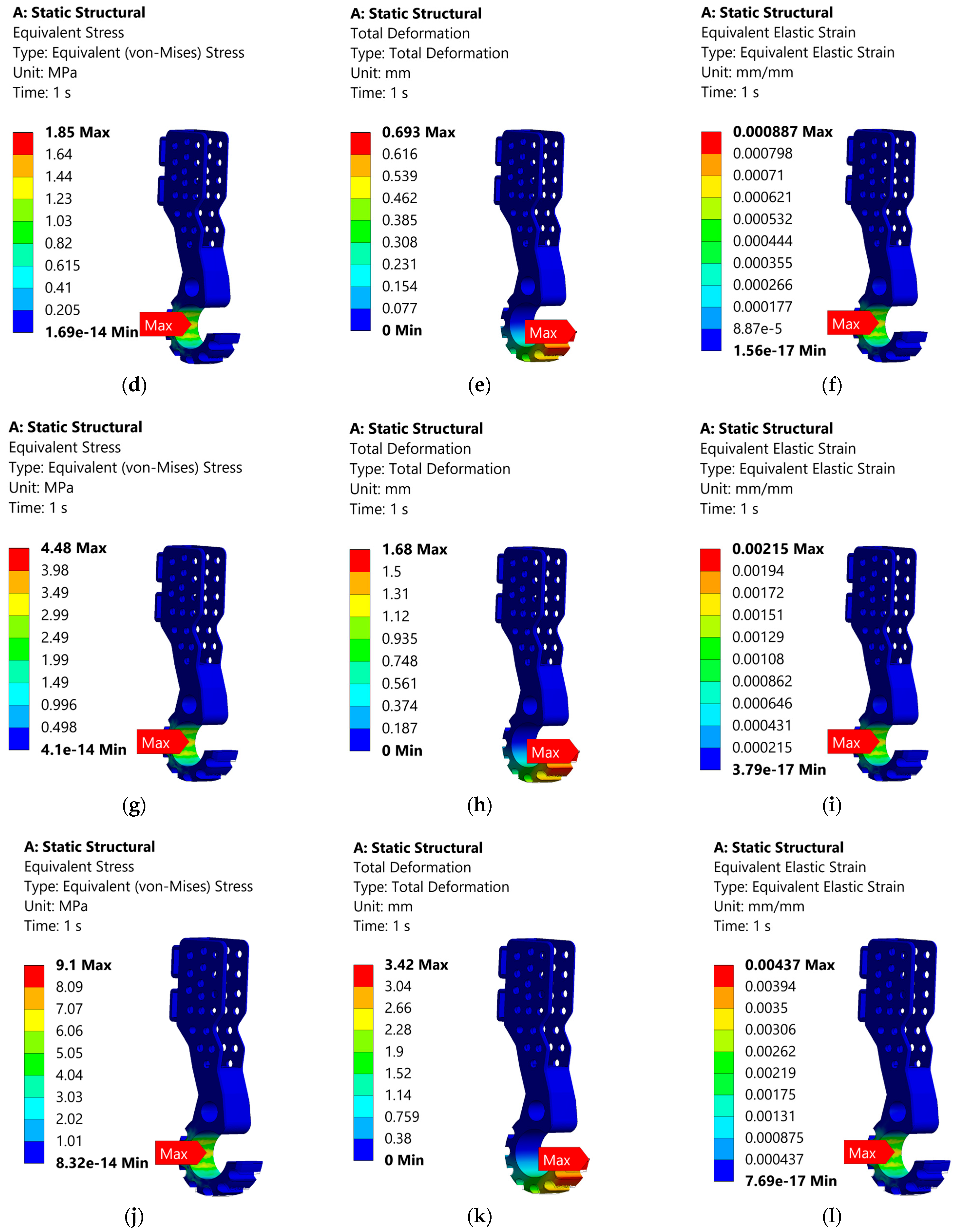
Table 4 and Figure 4 below show the results obtained for analysis of the Perforated Model. The following results were obtained: Equivalent Stress (Von Mises Stress), Total Deformation, and Equivalent Strain.

Table 4.
Mechanical properties of different breeds using perforated model.
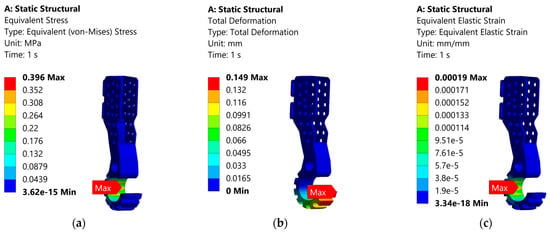
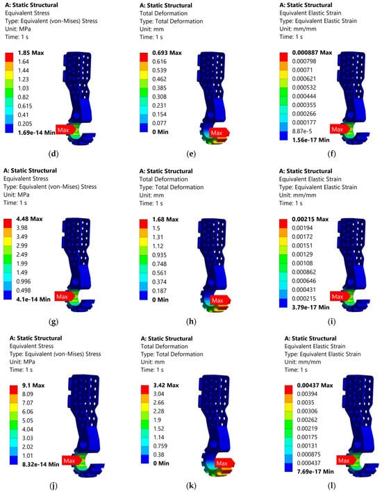
Figure 4.
(a–c) represent the results for Yorkshire Terrier, (d–f) represent the results for Cocker Spaniel, (g–i) represent the results for German Shepherd, and (j–l) represent the results for Newfoundland using perforated model.
3.3. Data Obtained for the Solid Model
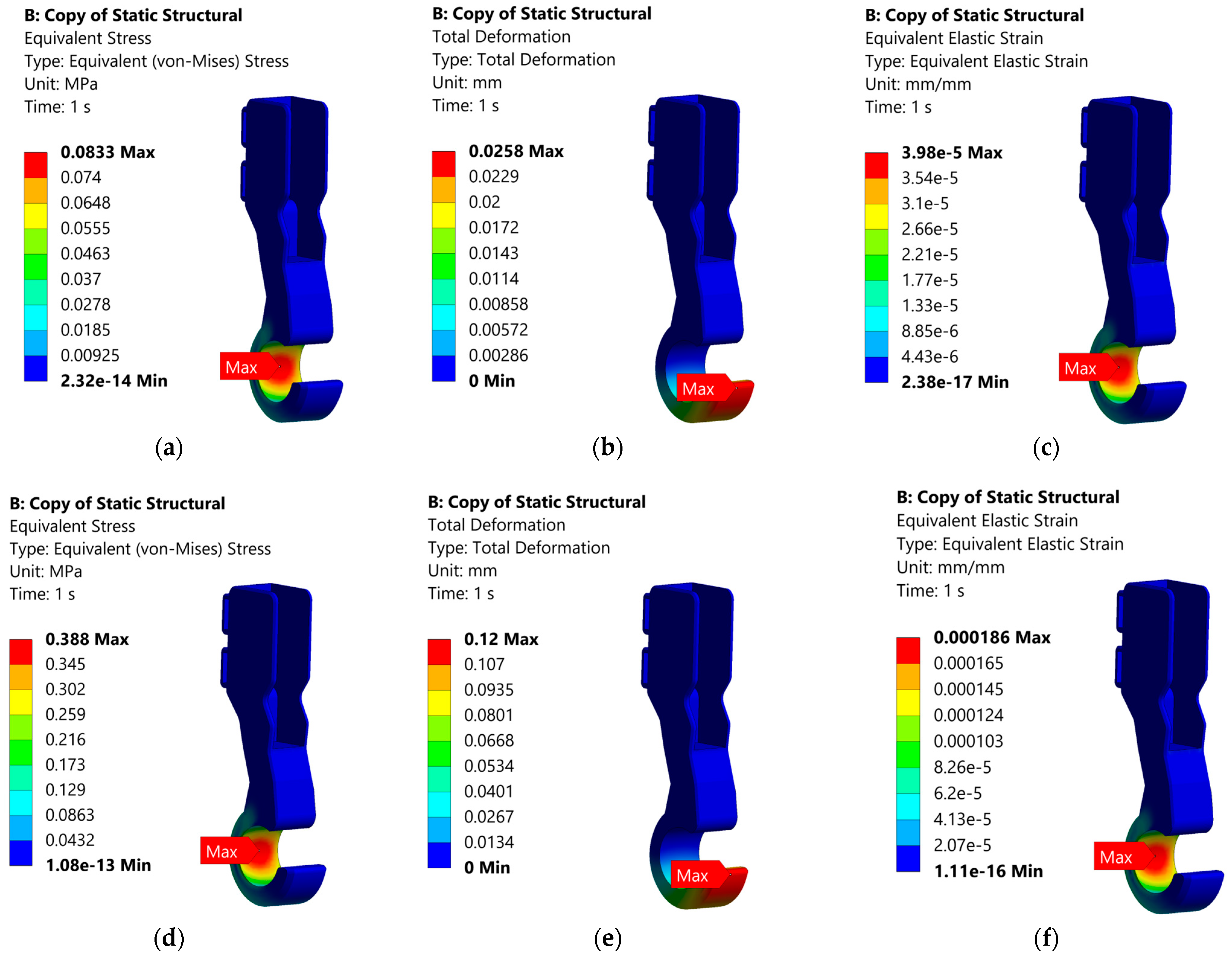
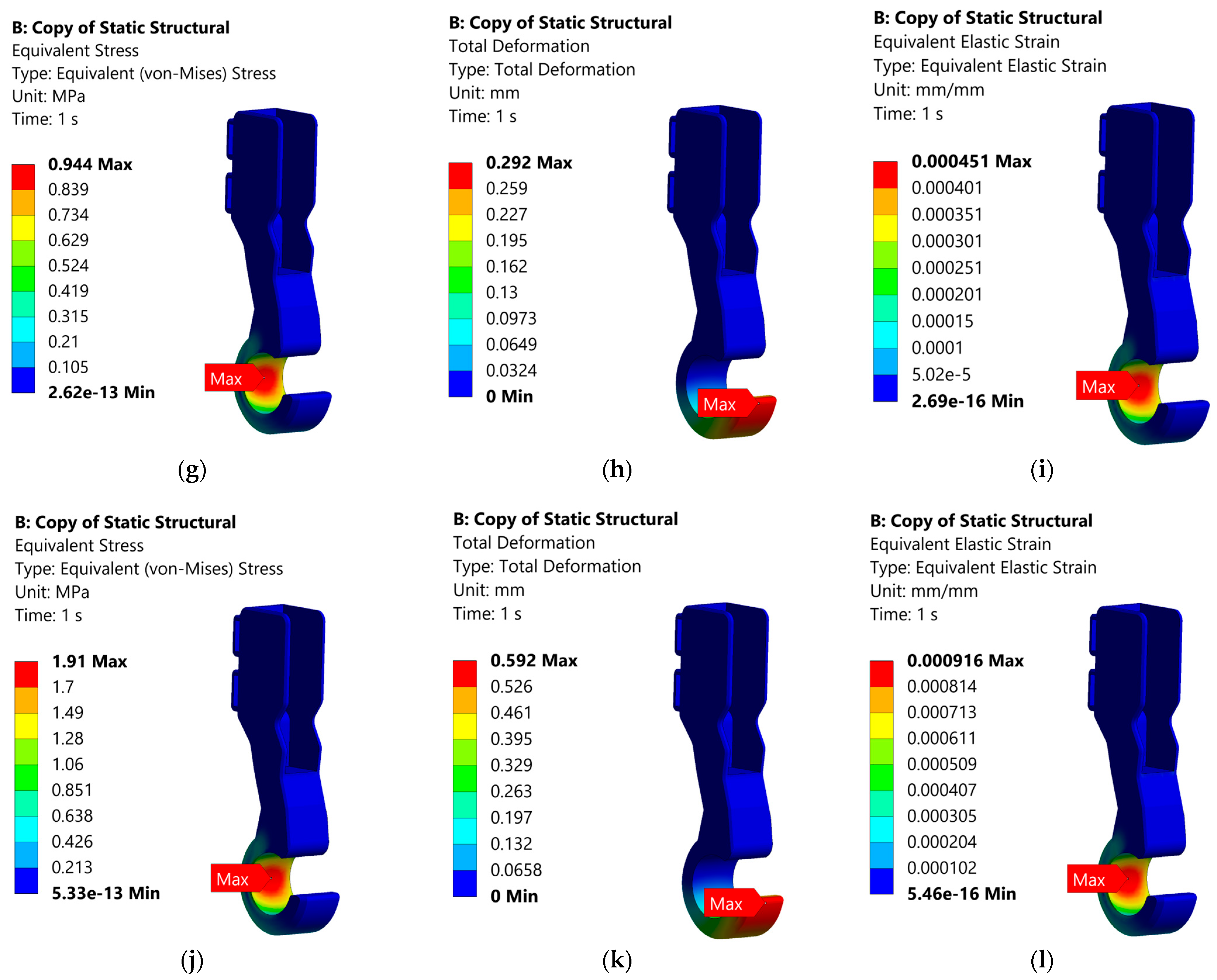
Table 5 and Figure 5 below show the results obtained for analysis of the Solid Model. The following results were obtained: Equivalent Stress (Von Mises Stress), Total Deformation, and Equivalent Strain.

Table 5.
Mechanical properties of different breeds using solid model.
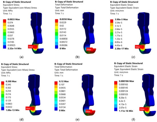
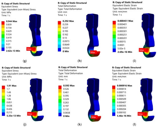
Figure 5.
(a–c) represent the results for Yorkshire Terrier, (d–f) represent the results for Cocker Spaniel, (g–i) represent the results for German Shepherd, and (j–l) represent the results for Newfoundland using solid model.
3.4. Criteria for Analysis
To proceed ahead with the analysis of the data obtained from the simulations, different criteria need to be set. The first criterion involves the evaluation of the Von Mises Stress obtained:
Using the Yield Strength of high impact ABS Plastic of 27.44 MPa (value from ANSYS), and assuming a Factor of Safety of 2, the critical value for Von Mises Stress becomes:
Von Mises Stress ≤ 13.72 MPa
The next criterion is that the Total Deformation should follow [17,18,19]:
1 mm ≤ Total Deformation ≤ 2–3 mm
There are currently no formal industry or veterinary standards that specify an exact deformation range, such as 1–3 mm, for prosthetic limbs in animals. However, this range is commonly referenced in prosthetic design literature based on observations of natural paw pad biomechanics and gait behavior. Research on canine paw pads has shown that during typical walking and standing, the soft tissues compress by up to a few millimeters, helping to absorb ground reaction forces and reduce impact-related stress. Studies such as those by Miao et al. [17] and other biomechanical analyses indicate that paw pads can reduce peak forces by up to 37%, highlighting their important role in shock absorption and load distribution. Based on this, prosthetic designs that produce less than 1 mm of deformation are often considered too stiff to replicate natural behavior, while deformation in the range of 1–2 mm offers moderate compliance. Deformations between 2 and 3 mm are viewed as optimal, as they more closely mimic the mechanical response of the biological paw pad during motion. While this range is not collected in an official guideline, it is supported by empirical evidence and serves as a useful design target in the development of realistic, comfortable, and functional prosthetics for animals. For static load-bearing evaluations in animal prosthetics:
- Ideal deformation: 1–3 mm
- Below 1 mm: too rigid
- Above 3 mm: too soft/unstable
These values should be interpreted in context with stress/strain results, material choice, and gait observations if available. The final criterion involves computing the critical value for the Equivalent Elastic Strain which can be calculated as:
Using the Yield Strength of high impact ABS Plastic of 27.44 MPa (value from ANSYS), and a Young’s Modulus value of 2090 MPa (value from ANSYS), the critical value for Equivalent Elastic Strain becomes:
Equivalent Elastic Strain ≤ 0.0131
From Equation (1) the minimum Factor of Safety was computed from the highest value of the von mises stress for both models to compare the two models.
4. Discussion
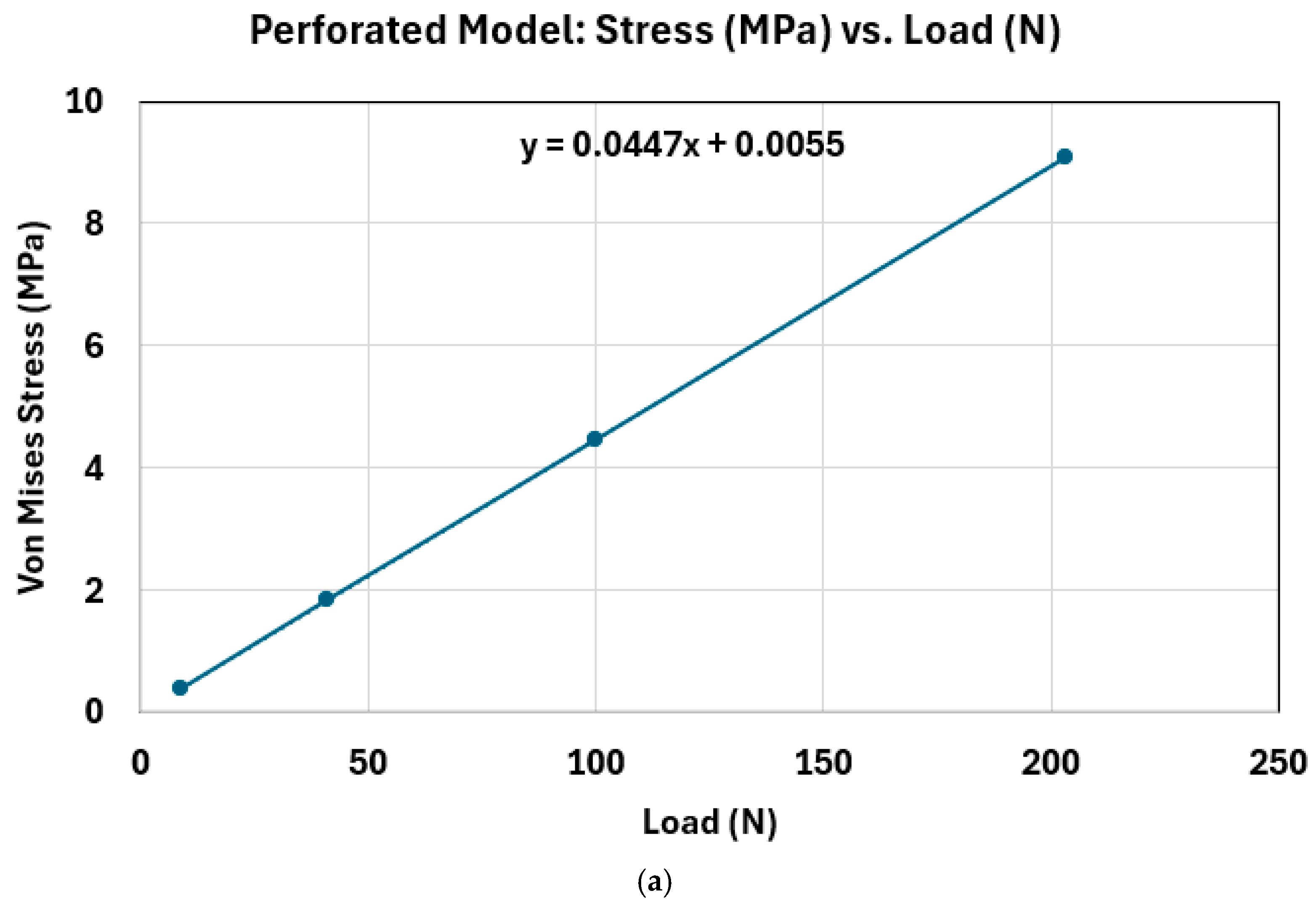
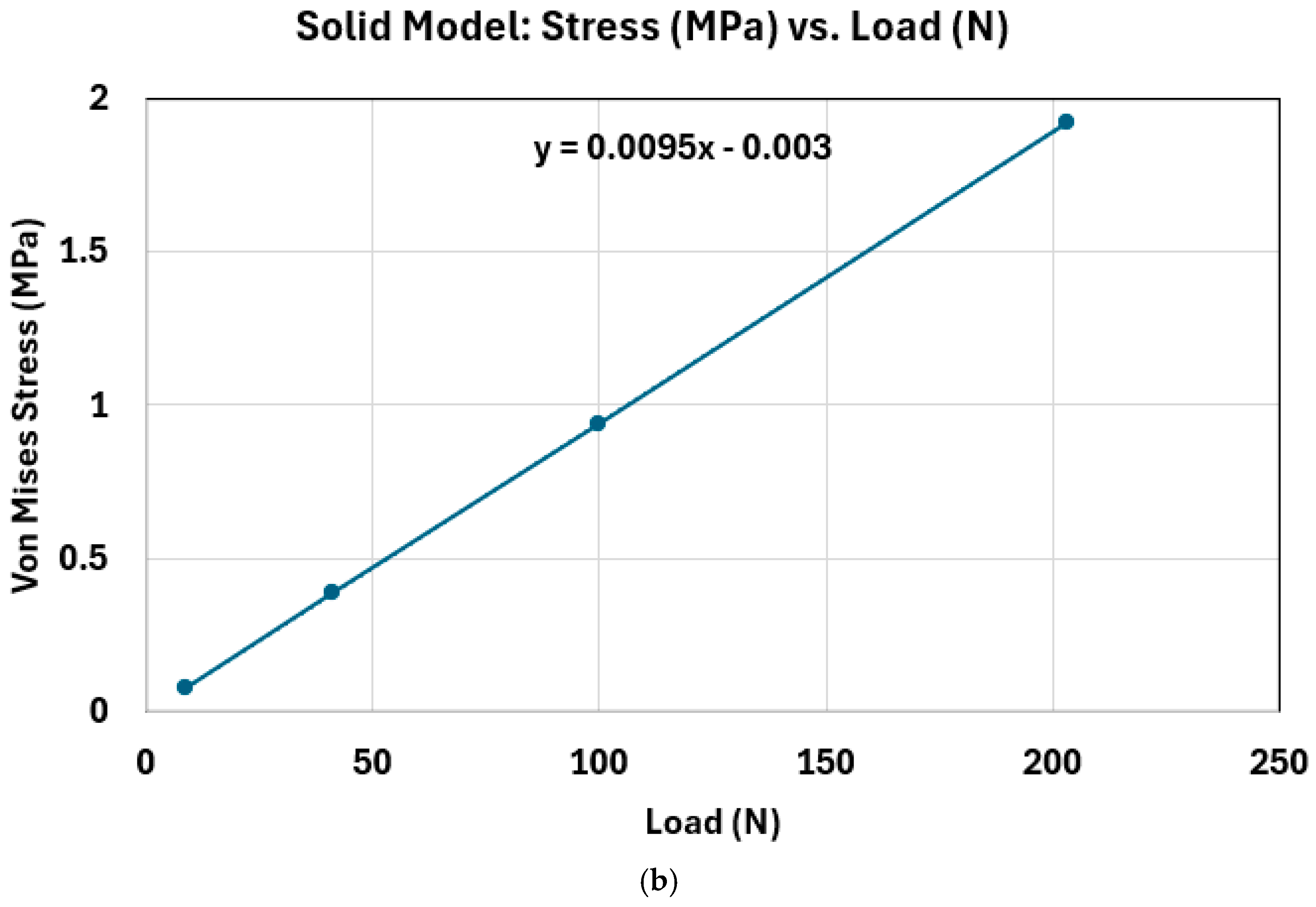
Before analyzing the results, data obtained in Table 4 and Table 5 show a proportional increase in the Von Mises stress with increasing load.
Figure 6 illustrates a clear trend: as the applied load increases on both models, the equivalent (von Mises) stress increases correspondingly, demonstrating a direct and nearly linear relationship between load and stress. However, what stands out in the comparison between Figure 2b and Figure 6a is the magnitude of the stress values. The Perforated Model in Figure 6a consistently exhibits much higher equivalent stress levels under the same loading conditions than the Solid Model in Figure 6b. This discrepancy is primarily attributed to differences in geometry and structural integrity. The Perforated Model includes design features such as holes and grooves, which significantly reduce its effective cross-sectional area. With less material available to distribute the applied load, stress is concentrated in the remaining structure, particularly around the geometric discontinuities. In contrast, the Solid Model retains a uniform cross-section, which allows for more even load distribution and better structural stiffness. As a result, it experiences lower stress under identical loading conditions. These findings underscore the impact of geometric design on mechanical performance, especially in components subjected to increasing loads. The presence of perforations weakens the structure’s ability to withstand stress, making it more susceptible to failure if not properly accounted for in design. Higher stress concentrations are more likely to occur in the thinner sections of the Perforated Model, as these areas are less capable of distributing the applied load evenly. This phenomenon is clearly visible in Figure 4, where the stress distribution is heavily concentrated around the narrow regions and near the edges of the holes. These localized stresses are a direct result of the geometry, which introduces discontinuities and reduces the effective load-bearing cross-sectional area. In addition to geometric factors, the Perforated Model also exhibits reduced overall structural stiffness compared to a solid counterpart. The presence of openings and grooves in the design increases flexibility, making the structure more prone to deformation when subjected to load. This added flexibility can lead to localized bending, which in turn elevates stress in certain regions, especially near notches or sharp transitions. The combination of reduced stiffness and increased deformation results in more severe stress localization, potentially accelerating the onset of material fatigue or failure. Thus, while the perforated design may offer benefits in weight reduction or design adaptability, it comes at the cost of mechanical performance and stability under stress. Following the criteria listed above in Section 3.4, the following tables were developed:
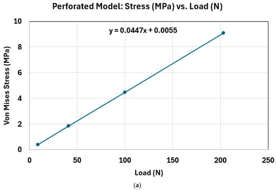
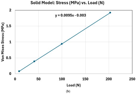
Figure 6.
(a) Stress vs. Load for the Perforated Model; (b) Stress vs. Load for the Solid Model.
Table 6 and Table 7 clearly show that the calculated Von Mises stress values for all the simulated dog breeds remain well below the critical threshold of 13.72 MPa for both the Solid and Perforated prosthetic models. This critical value represents the material’s yield strength—essentially the point beyond which permanent deformation would begin to occur. Since none of the stress values approach or exceed this limit, it indicates that the material remains within its elastic range throughout the loading conditions tested. In practical terms, this means that under the simulated loading conditions—representing the range of weights and activities typical for the various dog breeds—the prosthetic limb designs are mechanically sound. The material can withstand the applied forces without any risk of structural failure or irreversible deformation. As a result, both designs are deemed safe and reliable from an engineering standpoint, ensuring the prosthetics will maintain their shape and functionality during regular use. This also highlights the suitability of the chosen material and design approach for veterinary prosthetic applications, where safety, durability, and comfort are critical.

Table 6.
Analysis of Von Mises Stress for the Perforated Model.

Table 7.
Analysis of Von Mises Stress for the Solid Model.
Table 8 and Table 9 provide insights into the total deformation experienced by the prosthetic footpad models across different dog breeds. While most of the deformation values recorded in both models fall outside the optimal range of 1 mm to 3 mm, the data from Table 8 (Perforated Model) shows values that are noticeably closer to this desired range compared to those in Table 9, which represents the Solid Model. Notably, for the German Shepherd, the Perforated Model exhibited a total deformation that falls within the ideal range. This range is not arbitrary. As supported by prior studies [17,18,19], a total deformation below 1 mm indicates a structure that is too stiff, offering little to no shock absorption. In other words, the model does not compress or yield under pressure the way a natural dog paw would, potentially resulting in discomfort or long-term stress on the limb. A deformation between 1 and 2 mm is considered acceptable, suggesting moderate cushioning. A value between 2 and 3 mm is ideal—it means the prosthetic footpad mimics the compression behavior of a real paw, offering a balance between support and shock absorption. This biomechanical realism becomes even more important in dynamic activities like walking or running, where effective shock absorption helps prevent stress-related injuries and improves gait comfort. On the other end of the spectrum, deformation values exceeding 3 mm suggest excessive softness. In such cases, the prosthetic may lack the mechanical stability needed to properly support the animal’s weight, which could lead to instability or premature failure. As illustrated in Figure 4k, a significant displacement of the model from the wireframe reflects deformation that may compromise structural integrity. In summary, the closer alignment of the Perforated Model’s deformation values to the ideal range, particularly in the case of the German Shepherd, highlights its greater potential to deliver a more natural and biomechanically effective solution. This suggests that the Perforated Model may offer a better balance of stiffness and flexibility, allowing the prosthetic to function more like a biological paw and promoting better adaptation by the animal.

Table 8.
Analysis of Total Deformation for the Perforated Model.

Table 9.
Analysis of Total Deformation for the Solid Model.
Table 10 and Table 11 present the Equivalent Strain values for various dog breeds tested using both the Perforated and Solid prosthetic footpad models. In every case, the measured strain is well below the critical threshold of 0.0131 mm/mm. This is an encouraging outcome, as it confirms that all tested configurations remain within the elastic deformation range of the material. In other words, the models are experiencing reversible strain under load—meaning the material can return to its original shape once the load is removed. Remaining far below this strain limit is crucial for ensuring long-term structural integrity and functionality of the prosthetic device. High strain values approaching or exceeding the material’s elastic limit could lead to permanent deformation, compromising the prosthetic’s performance and safety. However, the results in both models suggest there is a significant margin before such concerns arise, indicating a low risk of material fatigue or failure even under repeated or prolonged use. This is especially important in prosthetic applications where durability and reliability are essential for the comfort and mobility of the animal. By staying well within safe strain limits, both the Perforated and Solid models demonstrate strong potential for real-world use, offering mechanical stability without posing undue stress on the limb or the prosthetic structure itself. Therefore, in terms of equivalent strain performance, both models meet the safety criteria and are suitable for further development or clinical application.

Table 10.
Analysis of Equivalent Strain for the Perforated Model.

Table 11.
Analysis of Equivalent Strain for the Solid Model.
By calculating the minimum Factor of Safety (FoS) for both the Perforated and Solid prosthetic models (Table 12), we gain important insights into their structural reliability under load. In engineering, a FoS greater than 2 is generally considered safe for most applications, and in this case, both models comfortably exceed that threshold. The Solid Model, with an exceptionally high FoS of 14.3, clearly demonstrates that it is structurally sound—but also suggests that it is overengineered for its intended use as a canine forelimb prosthetic. This excessive safety margin means the model uses significantly more material than necessary, leading to an unnecessarily heavy design that could be uncomfortable or impractical for a dog to wear. Furthermore, the added material increases manufacturing costs, making the design less efficient and economically viable. On the other hand, the Perforated Model achieves a more balanced result with a FoS of 3.01. This value is still well above the safety threshold, indicating reliable structural performance, but without the excessive material use found in the Solid Model. Its lighter weight makes it more suitable for animal prosthetics, where comfort, mobility, and realistic biomechanics are crucial. When this safety margin is considered alongside other important performance metrics—such as lower total deformation and adequate strain response—the Perforated Model proves to be not only structurally secure but also a more practical and cost-effective solution. Its design better mimics the natural feel and function of a canine limb, especially under static, load-bearing conditions like standing, making it an ideal candidate for real-world application.

Table 12.
Analysis of the Minimum Factor of Safety of Both Models.
5. Conclusions
Based on the findings from the Finite Element Analysis (FEA) simulations, the Solid Model demonstrated the strongest mechanical performance across all tested criteria. It consistently exhibited the lowest values for Von Mises stress, total deformation, and equivalent strain under all applied static loads. Additionally, it achieved a high Factor of Safety (FoS) of 14, clearly indicating exceptional structural reliability and a significant margin before failure. However, despite its superior mechanical performance, the Solid Model is not considered a practical choice for real-world application—especially for canine prosthetics—due to its excessive material use, resulting in a heavier structure. This not only affects user comfort but also presents challenges for large-scale production in terms of cost and material efficiency. In contrast, the Perforated Model offers a more balanced and realistic solution. While it did not outperform the Solid Model in all mechanical metrics, it still fell well within acceptable thresholds. The Von Mises stress values remained comfortably below the critical limit of 13.72 MPa, and its total deformation ranged closer to the ideal 1–3 mm target. This range is considered optimal for mimicking the cushioning effect of a natural paw, which is essential for comfort and shock absorption, particularly under load-bearing conditions such as standing. Furthermore, the Perforated Model maintained a Factor of Safety of 3.01—still well above the acceptable threshold for safety. Its reduced material usage makes it lighter, more cost-effective, and easier to manufacture, without sacrificing necessary structural integrity. It is important to note that this study was limited to static loading scenarios. In real-world settings, animals experience dynamic forces while walking, running, and changing gait. Future work should include testing under cyclic or impact loads to better simulate these conditions. Additionally, experimental validation of the FEA results, improved modeling of limb-socket interaction, and the application of more realistic boundary conditions would significantly enhance the accuracy and applicability of the study. Overall, while the Solid Model sets the benchmark for strength, the Perforated Model strikes a better balance between safety, comfort, and practicality for canine prosthetic applications.
Author Contributions
Conceptualization, K.K. and J.S.; methodology, K.K. and J.S.; software, J.S. and M.S.; validation, K.K. and J.S.; formal analysis, K.K. and J.S.; investigation, K.K. and J.S.; data curation, J.S. and M.S.; writing—original draft preparation, K.K., J.S. and M.S.; writing—review and editing, K.K. and J.S.; visualization, J.S. and M.S.; supervision, K.K.; project administration, K.K. All authors have read and agreed to the published version of the manuscript.
Funding
This research is funded by Institute for Society and Technology—UM Flint and The Hagerman Center for Entrepreneurship & Innovation.
Data Availability Statement
Data are contained within the article.
Conflicts of Interest
The authors declare no conflicts of interest.
References
- Bhuiyan, M.Z.H.; Khanafer, K.; Rafi, E.I.; Shihab, M.S. Non-Linear Hyperelastic Model Analysis and Numerical Validation of 3D Printed PLA+ Material Incorporating Various Infill Densities. Machines 2025, 13, 91. [Google Scholar] [CrossRef]
- Bhuiyan, Z.H.M.; Khanafer, K. Exploring the Nonlinear Mechanical Characteristics of 3D-Printed ABS with Varying Infill Densities. J. Manuf. Mater. Process. 2025, 9, 103. [Google Scholar] [CrossRef]
- Singh, S.; Ramakrishna, S. Biomedical Applications of Additive Manufacturing: Present and Future. Curr. Opin. Biomed. Eng. 2017, 2, 105–115. [Google Scholar] [CrossRef]
- Rahman, M.; Bennett, T.; Glisson, D.; Beckley, D.; Khan, J. Finite Element Analysis of Prosthetic Running Blades Using Different Composite Materials to Optimize Performance. In Proceedings of the ASME 2014 International Mechanical Engineering Congress and Exposition, Montreal, QC, Canada, 14–20 November 2014; Volume 10: Micro- and Nano-Systems Engineering and Packaging. [Google Scholar]
- Ismail, R.; Fitriyana, D.F.; Habibi, M.A.; Sugiyanto; Bayuseno, A. Computational Analysis of Running Prosthesis Design Using Finite Element Method. In Proceedings of the 2020 7th International Conference on Information Technology, Computer, and Electrical Engineering (ICITACEE), Semarang, Indonesia, 24–25 September 2020; pp. 288–293. [Google Scholar] [CrossRef]
- Mich, P.M. The Emerging Role of Veterinary Orthotics and Prosthetics (V-OP) in Small Animal Rehabilitation and Pain Management. Top. Companion Anim. Med. 2014, 29, 10–19. [Google Scholar] [CrossRef] [PubMed]
- Carr, B.J.; Canapp, S.; Petrovitch, J.L.; Campana, D.; Canapp, D.; Leasure, C.S. Retrospective Study on External Canine Limb Prosthesis used in 24 patients. Vet. Evid. 2018, 3, 1–13. [Google Scholar] [CrossRef]
- Anderson, D.E.; Jean, G.S. Management of Fractures in Field Settings. Vet. Clin. N. Am. Food Anim. Pract. 2008, 24, 567–582. [Google Scholar] [CrossRef] [PubMed]
- Teixeira, M.; Belinha, J. Review: Prosthetic Limb Replacement in Dogs. In Advances and Current Trends in Biomechanics; CRC Press: Boca Raton, FL, USA, 2021. [Google Scholar] [CrossRef]
- Wendland, T.M.; Seguin, B.; Duerr, F.M. Prospective Evaluation of Canine Partial Limb Amputation with Socket Prostheses. Vet. Med. Sci. 2023, 9, 1521–1533. [Google Scholar] [CrossRef] [PubMed]
- Arauz, P.G.; Chiriboga, P.; García, M.-G.; Kao, I.; Díaz, E.A. New Technologies Applied to Canine Limb Prostheses: A Review. Vet. World 2021, 14, 2793–2802. [Google Scholar] [CrossRef] [PubMed]
- Popov, V.V.; Muller-Kamskii, G.; Katz-Demyanetz, A.; Kovalevsky, A.; Usov, S.; Trofimcow, D.; Dzhenzhera, G.; Koptyug, A. Additive Manufacturing to Veterinary Practice: Recovery of Bony Defects after the Osteosarcoma Resection in Canines. Biomed. Eng. Lett. 2019, 9, 97–108. [Google Scholar] [CrossRef] [PubMed]
- Kastlunger, T. Design of Prototype Prosthesis for a Canine with a Right Front Limb Deformity as an Alternate Approach to Stabilize Gait and Withstand Gait Forces. Master’s Thesis, California Polytechnic State University, San Luis Obispo, CA, USA, 2020. [Google Scholar] [CrossRef]
- Motijo-Valenzuel, E.; Ruiz-Navarro, A.; Silva-Conreras, A.; Rubalcava-Aranda, J.; Samano-Hermosillo, E. Design and Validation with Finite Element Analysis of a Veterinary Application Prosthesis for Cervus nippon. October 2021. Revista de Investigación Académica Sin Frontera División de Ciencias Económicas y Sociales. Available online: https://www.researchgate.net/publication/355831761_Design_and_validation_with_finite_element_analysis_of_a_veterinary_application_prosthesis_for_Cervus_nippon (accessed on 7 July 2025).
- Dog Weight Chart: Weights of Popular Dog Breeds. Available online: https://dogslim.com/articles/dog-weight-chart.html (accessed on 7 July 2025).
- Fish, F.E.; Sheehan, M.J.; Adams, D.S.; Tennett, K.A.; Gough, W.T. A 60:40 Split: Differential Mass Support in Dogs. Anat. Rec. 2021, 304, 78–89. [Google Scholar] [CrossRef] [PubMed]
- Miao, H.; Fu, J.; Qian, Z.; Ren, L.; Ren, L. How does the canine paw pad attenuate ground impacts? A multi-layer cushion system. Biol. Open 2017, 6, 1889–1896. [Google Scholar] [CrossRef] [PubMed]
- Sierra-Rodríguez, A.; Molines-Barroso, R.J.; Martínez, M.A.; Abenojar-Buendía, J.; Lázaro-Martínez, J.L.; Orejana-García, A.M. Reliability and Validity of the Orthotic Deformation Test. Appl. Sci. 2024, 14, 8378. [Google Scholar] [CrossRef]
- Mei, Y. Investigation of the Microstructure and Mechanical Properties of the Domestic Cat’s Paw Pads. Thai J. Vet. Med. 2022, 52, 359–367. [Google Scholar] [CrossRef]
Disclaimer/Publisher’s Note: The statements, opinions and data contained in all publications are solely those of the individual author(s) and contributor(s) and not of MDPI and/or the editor(s). MDPI and/or the editor(s) disclaim responsibility for any injury to people or property resulting from any ideas, methods, instructions or products referred to in the content. |
© 2025 by the authors. Licensee MDPI, Basel, Switzerland. This article is an open access article distributed under the terms and conditions of the Creative Commons Attribution (CC BY) license (https://creativecommons.org/licenses/by/4.0/).

