Article

Effect of Cross-Section Designs on Energy Absorption of Mechanical Metamaterials

Department of Mechanical and Industrial Engineering, University of Illinois Chicago, Chicago, IL 60607, USA
*
Author to whom correspondence should be addressed.
Designs 2025, 9(5), 106; https://doi.org/10.3390/designs9050106
Submission received: 6 August 2025 / Revised: 27 August 2025 / Accepted: 3 September 2025 / Published: 7 September 2025

Abstract

Numerous studies have examined various geometric designs in cellular structures, yet the role of cross-sectional geometry remains underexplored. Cross-sections significantly influence the effective material properties of architected materials, where stress concentrations at junctions can reduce structural strength. This study investigates how different cross-sections affect energy absorption efficiency in both bending- and stretching-dominated cellular structures. Five classes of lattice structures, each designed with four distinct cross-sections, were fabricated using a custom stereolithography printer. Mechanical performance—specifically energy absorption and energy absorption efficiency—was evaluated through physical simulation and experimental testing. The results show that selecting optimal cross-sections can enhance yield stress by an average of 35% for cubic, 39% for BCC, 22% for BCCZ, and 41% for FCC structures. These findings demonstrate the critical impact of cross-sectional geometry on mechanical behavior. Both experimental and finite element analysis-based homogenization approaches were employed to validate results. The study proposes cross-section design guidelines aimed at optimizing strength-to-weight ratios, offering valuable insights for the development of high-performance mechanical metamaterials.

1. Introduction

Mechanical collisions, such as car accidents and industrial machinery impacts, have become increasingly prevalent [1,2]. This requires the urgent development of applications with high energy absorption efficiency and desired mechanical strength. Among these, sandwich structures are well known for their strong energy absorption capacity, consisting of solid skins and a core layer [3,4]. Studies indicate that under flatwise compression, the core primarily absorbs energy [5], whereas under edgewise loading, both the core and solid skins contribute significantly [5]. Consequently, analyzing the core structure is critical. Prior research has shown that low-density cores provide superior cushioning performance [3]. Lightweight cellular materials, characterized by low relative density and excellent impact resistance, have thus attracted considerable research interest [6,7]. These materials are typically categorized into three types: open/closed-cell foams, honeycombs, and lattice structures [8]. Among them, lattice structures stand out due to their ease of customization and control over design variables, as they consist of strut elements and connecting nodes [9,10]. However, their high porosity, small unit cells, and complex interconnections present significant challenges for traditional manufacturing methods such as computer numerical control (CNC) machining, molding, and casting [11,12], thereby limiting their widespread application. Recent advances in additive manufacturing (AM) have addressed many of these limitations. By fabricating components layer by layer, AM enables the production of complex, hollow, and highly customized structures that are otherwise difficult to achieve [13,14,15]. AM progresses offer researchers greater freedom to design and optimize lattice structures tailored for specific, on-demand functionalities.
Enhancing energy absorption efficiency in lattice structures can be achieved through various methods. One major strategy involves tailoring unit cell geometries and arrangements. For example, Zhang et al. developed a 3D hybrid lattice combining different unit cell types, enabling controlled failure during compression tests based on the relative densities of these cells, thereby strengthening strengthens the plateau phase [16]. Similarly, Lu et al. discovered that aligning unit cells with ligament directions enhances energy absorption [6]. Meza et al. introduced a hierarchical structure by merging various unit cell sizes, which improved mechanical properties [17]. Tancogne-Dejean et al. combined simple cubic (SC), body-centered cubic (BCC), and face-centered cubic (FCC) structures to create an elastically isotropic truss lattice, forming strong stretching-dominated networks [18]. Inspired by natural systems, Dara et al. created a 3D flower lattice based on the Lotus leaf by combining multiple circular slant members into a single unit cell, achieving a maximum energy absorption of 0.5 kJ/kg [19]. Similarly, Sharma et al. drew inspiration from the Euplectella aspergillum, integrating two closed cells with two open cells into a single unit to maximize the energy absorption efficiency [20]. Sun et al. developed a hybrid unit cell by combining octet and bending-dominated structures, enhancing energy absorption without compromising stiffness or strength [7]. Wang et al. devised a novel unit cell inspired by biomimetics, combining varying scale sizes of BCC and SC structures. This new lattice design achieves a maximum energy absorption efficiency of 0.696, which significantly surpasses that of a single BCC structure (0.518) [21]. He et al. also developed a theoretical model about loofah’s inner fibers to guide the design of energy-absorbing architectures [22]. Another strategy involves optimizing the truss cross-section to improve buckling and plastic yielding. However, much of this work remains theoretical due to fabrication challenges, with limited experimental validation. For instance, Niknam et al. demonstrated that a graded design with asymmetric variations in relative cell density can significantly enhance energy absorption efficiency [23]. Bai et al. designed graded-density struts with radii increasing from the middle to the ends, reducing stress concentration at nodes [24]. Qi et al. transformed uniform circular struts into trapezoidal ones, thereby improving both the elastic modulus and reducing the lattice structure’s elastic anisotropy [25]. Additionally, Hamzehei et al. introduced a DNA-inspired lattice structure with a graded wall thickness across layers, significantly enhancing energy absorption [26]. Alkhatib et al. demonstrated that increasing the wall thickness can boost energy absorption efficiency [27]. Gharehbaghi et al. utilized two materials to print lattice structures with a core–shell structure in the cross-section of the truss, achieving much higher energy absorption compared to lattices made from a single material [28]. Furthermore, Guo et al. introduced a novel truss design featuring capsule-shaped cavities within a BCC lattice, which increases the energy absorption efficiency by 22.8% compared to the conventional BCC structure [29]. These studies highlight significant progress in optimizing lattice structures for enhanced mechanical properties and energy absorption efficiency. However, most research has focused on strut size variations, with limited attention to the role of geometry. There is a paucity of research on how different shapes impact lattice structures. In addition, for a bending strut, the cross-section shape determined the strut’s elastic and plastic behavior. However, it is still unclear how the cross-section geometry affects the periodic lattice structure. Addressing this gap, this study investigates the influence of varying strut cross-sections. We employ different base materials for cell manufacturing using an SLA printing process. Comparative studies within each lattice structure family, wherein members underwent alterations in their cross-sections, revealed the impact of cross-section design and base material choice on the resultant energy absorption properties. It is important to note that our comparison focused solely on variations within the same lattice structure family, rather than across different families.
Figure 1 illustrates the methodological flowchart of this study. The rest of the paper is organized as follows: Section 2 details the structure of lattices in detail, including the unit cell structure, cross-section geometry, mathematical function for the elastic response, and calculation of energy absorption efficiency. Also, the material, fabrication techniques, hypercube design, and compression measurements are described in this session. Section 3 demonstrates experimental results including the strain–stress curve and the energy absorption efficiency. Section 4 summarizes the paper and discusses the design guidelines.

2. Research Methodology

2.1. Structure Specimens

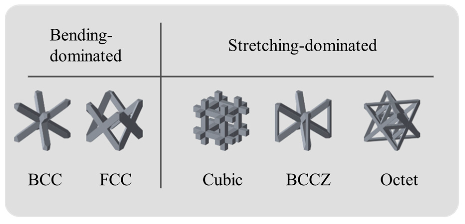
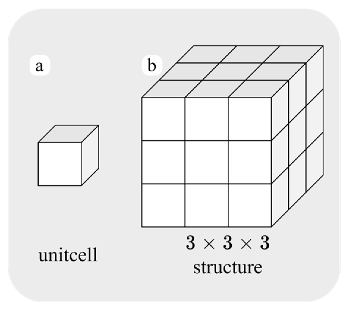
In this study, five types of unit cells (Figure 2) are selected to construct lattice structures. Each unit cell consists of solid-filled struts interconnected in specific patterns. These cellular solids exhibit different mechanical behaviors based on their node connectivity, undergoing either bending or stretching dominated deformations [30]. Notably, bending-dominated unit cells display a longer, flatter plateau in their stress–strain response compared to their stretching-dominated counterparts. This characteristic makes them more fitting for energy absorption applications [31]. Accordingly, this study focused on two bending-dominated unit cell structures (BCC, and FCC) [32,33], alongside three stretching-dominated structure (cubic, BCCZ, and octet) [34,35,36], to facilitate a comprehensive analysis. Based on the findings of Yang et al., increasing the cell size diameter from 3 mm to 5 mm reduces the percentage deviation of the volume fraction from 20.8% to 8.3%. Therefore, the size of each unit cell in this study was set to 5.97 × 5.97 × 5.97 mm [37]. In this study, a homogenization analysis will be conducted. Alkhatib et al., have demonstrated the sufficiency of a 3 × 3 × 1 lattice configuration along with its benefit of reduced computational costs [27]. Majari et al. reported that smaller cell sizes (27-cell configuration) provide more uniform stress distributions compared with an 8-cell configuration [38]. To maintain cubic symmetry and further optimize computational efficiency, the final lattice structure is designed as a 3 × 3 × 3 configuration. The overall lattice structure measured 17.91 × 17.91 × 17.91 mm (Figure 3). Also, lattices constructed from bending-dominated unit cells exhibited bending-dominated properties, similar to how lattices built from stretching-dominated cells displayed stretching-dominated characteristics [31,39].

2.2. Strut Cross-Section Design

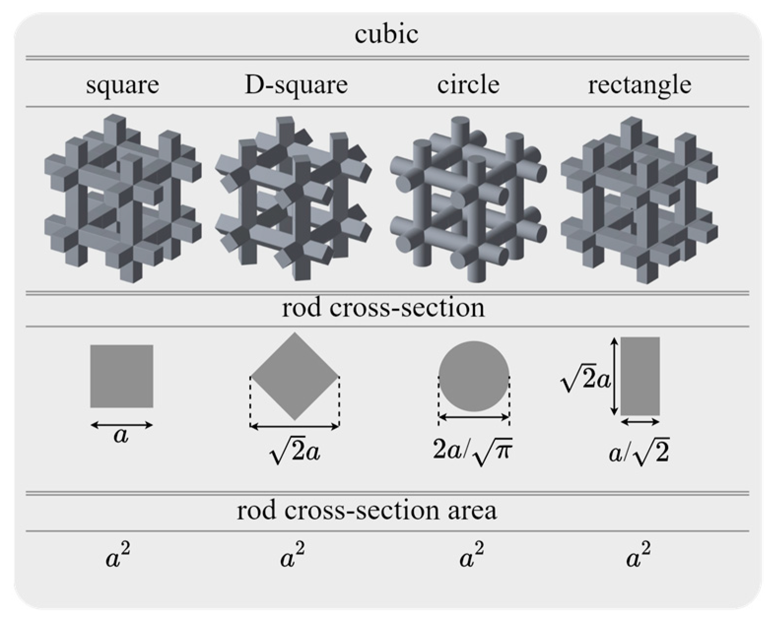
In this investigation, four types of cross-sectional shapes were selected for analysis: a square oriented horizontally, a diagonally positioned square (termed D-square), a circle, and a rectangle (as illustrated in Figure 4). To maintain objectivity in the comparative analysis, the area of each cross-sectional shape was standardized, allowing the analysis to focus solely on the influence of geometrical shape on the mechanical properties of the lattice structures. These cross-sectional shapes were then combined with the five-unit cell structures. This integration resulted in the formation of twenty unique specimens, each representing a different combination of unit cell structure and cross-sectional shape, as presented in Figure 5. In addition, all specimens have the same relative density of ρ = 0.15. To achieve this target volume fraction of 15%, the corresponding values of a were determined and are summarized in Table 1.

2.3. Elastic Response

For the above-designed structures, the elastic stress–strain relationship can be written as:
ε 1 ε 2 ε 3 ε 4 ε 5 ε 6 = S 11 S 12 S 13   S 22 S 23     S 33 0           0         0     0           0         0     0           0         0             S y m .         S 44 0 0   S 55 0     S 66 σ 1 σ 2 σ 3 σ 4 σ 5 σ 6
The cubic, BCC, and octet structures have cubic symmetry, and their elastic response can be described by three independent elasticity constants (S11 = S22 = S33, S12 = S13 = S23, S44 = S55 = S66). While the BCCZ and FCC structures have nine independent elasticity constants.
For the structures with cubic symmetry, Young’s modulus is calculated as [40]:
1 E = S 11 2 S 11 S 12 S 44 2 l 1 2 l 2 2 + l 2 2 l 3 2 + l 1 2 l 3 2
While the Young’s modulus of the other structures is calculated as:
1 E = l 1 4 S 11 + l 2 4 S 22 + l 3 4 S 33 + 2 l 1 2 l 2 2 S 12 + 2 l 2 2 l 3 2 S 23 + l 2 2 l 3 2 S 44 + l 1 2 l 3 2 S 55 + l 1 2 l 2 2 S 66
where Sij are the elastic compliance constants (with the calculation method described in Section 3.1) and l1, l2, l3 are the direction cosines. For example, to calculate Young’s modulus in the x-direction ([1,0,0]), we will have l1 = 1, l2 = l3 = 0, and 1 E 11   = S11 → E11  = 1 S 11 . Variations in cross-sectional area resulted in differences in Sij, which in turn led to different effective Young’s modulus.

2.4. Energy Absorption Efficiency

The following equation is used to calculate energy absorption efficiency [41]:
η ε = 0 ε 0 σ ε d ε σ ( ε 0 )
d η ε d ε | ε = ε d = 0
where η represents the efficiency of energy absorption, ε is the compression strain, σ is the compression stress, ε0 is the nominal strain observed in the experiment, while εd stands for the densification strain. As the strain reaches the densification strain level, the efficiency of energy absorption nears its peak value.

2.5. Manufacturing Process

Specimens were fabricated using a lab-developed SLA printer equipped with a Raspberry Pi 4 microcontroller (Cambridge, UK) and a DLP PRO 4500 UV source (Wintech, CA, USA). The design model was created in SolidWorks (Version:2024, MA, USA) and exported as an STL file. The STL file was then processed by the custom SLA printer’s slicing software before printing the objects. Printing was performed layer by layer using UV light to polymerize the resin, with a layer thickness of 0.05 mm (Figure 6). Following fabrication, the specimens were cleaned in an ultrasonic bath (Kealive, Changchun, China) with ethanol for 120 s to remove residual liquid resin. A subsequent post-curing step was carried out under UV light (Uspicy, CA, USA) for 30 s to enhance the mechanical properties of the lattice structures.

2.6. Mechanical Testing Experiments

2.6.1. Based Material

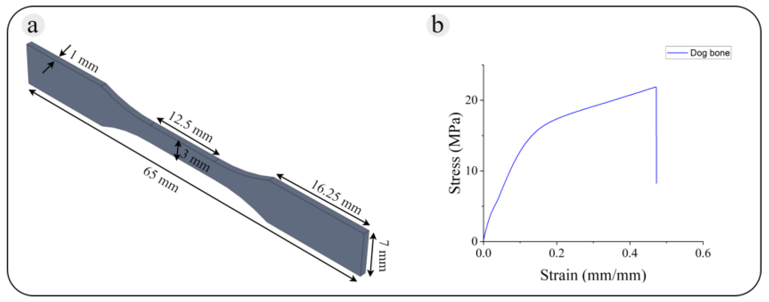
Dogbones (Figure 7), fabricated via the SLA process described in Section 2.5, were used to establish a baseline mechanical properties of the materials employed for lattice fabrication. In this study, the gauge length of each dogbone was set to 25 mm, a standard dimension for assessing the tensile strength of plastics and resin materials. Tensile tests were conducted using an Instron 3365 dual-column universal testing machine at a constant crosshead speed of 13.95 mm min−1, equating to a tensile strain rate of 0.558 min−1 based on the dogbone specimen’s dimensions. A selection of materials, including Spot-E (Spot_e), EnvisionTEC LS600 (Yellow), Makerjuice Standard (Makerjuice), and Surgical Guide (Bio), was chosen due to their varied elasticity moduli (E). The measured mechanical properties of these materials are summarized in Table 2.

2.6.2. Specimens

As seen from Table 3, three experimental variables were considered for the specimens fabricated in this study: structure type, cross-section, and fabrication material (resin). Although it is common practice in studying the effective mechanical properties of architected materials to consider their volume fraction as one of the design variables, all structures are designed to have a volume fraction of 15% since the focus of this research is on the effect of different cross-sections.
Two sets of samples were printed, each set has 20 specimens. For the first set, all the samples were fabricated by Makerjuice standard resin, see Table 4.
For the second set, the sample points were set by the design of the experiment sing the Optimal Latin hypercube design (Opt LHD). The sample points and the design variables related to this set are presented in Table 3.
These tables explain the design variables of each sample. For example, consider specimen #10 (3,1,2) in Table 5, these values indicate that this sample is a BCCZ structure, it has a square cross-section, and was printed with EnvisionTEC LS600 material (MI, USA).

2.6.3. Compression Experiment

Compression tests were conducted using an Instron 3365 dual-column universal testing machine (Massachusetts, USA). The compression speed was set at 10 mm min−1, corresponding to a constant strain rate of 0.1 min−1, considering the size of the lattice structure. For each geometry, three replicates were tested. These tests are critical for evaluating the material’s energy absorption capacity in cellular structures. The effective mechanical properties of architected materials used to evaluate energy absorption efficiency are listed as follows:
  • Compressive modulus of elasticity.
  • Yield stress.
  • Deformation beyond the yield point.
  • Compressive strength.

3. Results

3.1. Homogenized Stiffness

For the periodic truss structures, it is a common practice to obtain their effective mechanical response by numerical homogenization approach for a single representative unit cell [42,43,44]. In this research, a Matlab implementation [45] of the computational homogenization method is used to compute the mechanical properties of the truss structures. The code outputs the homogenized stiffness tensor (C = S−1) of the representative unit cell of a given truss structure in matrix notation. The isotropic base material used in homogenization is defined by two independent elasticity constants, Young’s modulus (E = 1) and its Poisson’s ratio (ν = 0.3). Each truss structure unit cell cube is discretized for the FEA mesh into 60 × 60 × 60 hexahedral elements.

3.2. Bending-Dominated Lattice Structures

Figure 8 shows the specimens (only for the first sample set) before and during the compression experiment. It also demonstrates each tested specimen’s stress–strain curve and energy absorption efficiency.
Figure 8c presents the correlation between energy absorption efficiency and strain for the four distinct structures. Each curve features several peaks and troughs, attributed to the instability in the plateau region. Among the tested designs, the cubic_DSqr structure reaches the highest energy absorption efficiency. Moreover, the cubic_Sqr structure demonstrates the lowest densification strain when its energy absorption efficiency peaks.

3.2.1. BCC Lattice Structures

Figure 8e illustrates the strain–stress results of BCC structures with different cross-sections. In terms of modulus of elasticity in compression, the rankings from highest to lowest are as follows: the BCC structure with a square cross-section (BCC_Sqr) is at the top, followed by the rectangular cross-section (BCC_Rect), the diagonal-square cross-section (BCC_DSqr), and finally, the circular cross-section (BCC_Circ). It is noteworthy that BCC_Rect and BCC_DSqr exhibit similar compressive moduli. The BCC_Sqr’s modulus is about 50% higher than both BCC_Rect and BCC_DSqr, and 114% higher than that of BCC_Circ. For the yield stress, BCC_Sqr has the maximum yield stress value, which is about 42% larger than BCC_DSqr and BCC_Rect, and 113% larger than BCC_Circ. Despite having the same printing process and relative densities, the BCC_Sqr and BCC_Circ samples show markedly different yield stresses. This is expected, as the BCC is a bending-dominated cellular structure, and changes in the cross-section of its struts directly influence their bending resistance, leading to significant variations in mechanical behavior. In addition, after reaching the yield point, all BCC specimens exhibit a long, flat plateau characteristic of bending-dominated behavior, followed by a sharp increase in stress beyond ε = 0.65.
Figure 8f shows the energy absorption efficiency result of four different BCC lattice structures. BCC_Sqr and BCC_Rect demonstrate similar trends and reach their maximum energy absorption efficiency at nearly the same strain level. Excluding the BCC_Circ structure, the other structures exhibit comparable values for maximum energy absorption efficiency. Moreover, the BCC_Circ, BCC_DSqr, and BCC_Sqr structures show smooth ascending lines in their graphs. Notably, the peak energy absorption efficiency for these structures is significantly lower than that observed in the cubic structures.

3.2.2. FCC Lattice Structures

The strain–stress curve (Figure 8k) of the FCC structure demonstrates that a square cross-section (FCC_Sqr) exhibits the highest compressive modulus of elasticity among the four FCC types. The FCC samples with a circular cross-section (FCC_Circ) and a diagonal-square cross-section (FCC_DSqr) both have a moderate compressive modulus of elasticity. The specimen with a rectangular cross-section (FCC_Rect) possesses the lowest modulus of elasticity. The compressive modulus of FCC_Sqr is 32% higher than FCC_Circ, 51% higher than FCC_DSqr, and 84% greater than the FCC_Rect specimen.
In terms of yield stress, it is highest in FCC_Sqr, followed by FCC_Circ, FCC_DSqr, and finally FCC_Rect. The yield stress of FCC_Sqr is 29% greater than FCC_Circ, 55% higher than FCC_DSqr, and 82% more than FCC_Rect. In addition, all FCC specimens exhibit a sharp drop in stress immediately after the yield point, indicating loading-velocity sensitive behavior [46]. This is followed by a long, flat plateau indicative of bending-dominated behavior.
Figure 8l demonstrates that FCC_Circ has the highest energy absorption efficiency and which also reaches this maximum at the lowest strain value (0.321). Conversely, FCC_Rect takes the longest time to reach its point of maximum energy absorption efficiency. Moreover, among all the structures, FCC_Rect exhibits the largest valley, indicating a significant difference in energy absorption efficiency at different strain levels.

3.3. Stretching-Dominated Lattice Structures

3.3.1. cubic Lattice Structures

Figure 8b displays the strain–stress results for four different types of cubic lattice structures. When comparing the modulus of elasticity, the ranking from highest to lowest is as follows: the circular cross-section (cubic_Circ), the diagonal-square cross-section (cubic_DSqr), and the rectangular cross-section (cubic_Rect). The results indicate that the modulus of elasticity for cubic_Circ is approximately 10% higher than cubic_DSqr, 25% higher than cubic_Rect, and 84% higher compared to the cubic_Sqr. In terms of yield stress, both cubic_DSqr and cubic_Circ exhibit similar values, which are 26% greater than that of cubic_Rect and 85% higher than cubic_Sqr. Notably, despite all samples sharing the same relative density and being produced with identical SLA printing processes and parameters, their yield stresses vary significantly. This variation can be attributed to the differences in the cross-sectional shapes of the struts.

3.3.2. BCCZ Lattice Structures

Figure 8h displays the strain–stress results for BCCZ specimens. In terms of the modulus of elasticity in compression, the BCCZ specimen with a diagonal-square cross-section (BCCZ_DSqr) ranks the highest, exhibiting a modulus that is 19% higher than the other cross-section shapes. Notably, the BCCZ specimens with a square cross-section (BCCZ_Sqr), a circular cross-section (BCCZ_Circ), and a rectangular cross-section (BCCZ_Rect) all demonstrate equal modulus of elasticity. Regarding yield stress, BCCZ_DSqr shows superior performance, being 20% greater than BCCZ_Sqr, 31% higher than BCCZ_Circ, and 38% higher than BCCZ_Rect. Modification in the strut cross-section has a more pronounced effect on the mechanical behavior of the BCCZ specimens compared to the BCC specimens, which is an anticipated result. Unlike BCC materials, the BCCZ materials exhibit stretching-dominated behavior beyond the yield point. As such, alterations in their struts’ bending resistance do not significantly impact their mechanical behavior as it does in bending-dominated materials. In addition, all BCCZ specimens display multiple drops in their stress–strain curves after the yield point, indicative of stretching-dominated behavior.
The energy absorption efficiency of the BCCZ structures is shown in Figure 8i. Due to the instability of the plateau region, all curves exhibit multiple peaks and valleys. BCCZ_Circ and BCCZ_Sqr reach their maximum energy absorption efficiency at similar strain levels. Similarly to cubic structures, BCCZ_DSqr achieves the highest energy absorption efficiency value.

3.3.3. octet Lattice Structures

Figure 9b shows the stress–strain response of four different octet samples. In terms of the compressive modulus of elasticity, the samples rank as follows, from highest to lowest: the octet specimen with a square cross-section (octet_Sqr) tops the list, followed by the diagonal-square cross-section (octet_DSqr), and then the octet specimens with circular (octet_Circ) and rectangular (octet_Rect) cross-sections. Notably, the octet_Sqr’s modulus of elasticity is 28% higher than that of octet_DSqr and 64% higher than the moduli of the octet_Circ and octet_Rect. Regarding yield stress, it ranks from highest to lowest as follows: octet_Sqr, octet_Rect, octet_Circ, and octet_DSqr. The yield stress of the octet_Sqr specimen is 18% greater than octet_Rect, 36% higher than octet_Circ, and 40% more than octet_DSqr. The stretching dominated behavior of octet cellular structures means that the cross-section of their struts does not significantly affect their mechanical properties. All octet specimens exhibit multiple drops in their stress–strain curves after the yield point, indicative of stretching-dominated behavior.
The energy absorption efficiency results of octet lattice structures are shown in Figure 9c. All the curves follow a similar pattern with comparable peaks and valleys. Octet_Circ reaches the highest energy absorption efficiency value (0.559) at the largest strain (0.507). octet_DSqr, octet_Rect, and octet_Sqr have similar maximum energy absorption efficiency values of 0.477, 0.484, and 0.496, respectively.
Additionally, it has been observed that when constructed from the same material, the Dsqr offers better energy absorption in both cubic and BCCZ samples. Conversely, the Sqr is more effective for BCC structures, while the Circ performs better with FCC and octet samples.

3.4. Optimal LHD Samples

A second series of compression experiments is conducted to investigate the effect of using different base materials (resin) on the compression response and energy absorption efficiency of the truss-based cellular structures. For this study, the specimens in Table 5 were fabricated using the same method described in Section 3.1. The results of these experiments as well as homogenization study results are reported in terms of engineering stress versus the axial engineering strain curve, relative Young’s modulus, and energy absorption efficiency.
The values reported in Figure 10 are normalized with the base materials’ Young’s moduli (values reported in Table 2). Figure 10 confirms that changing the strut’s cross-section and the base material considerably influences the effective mechanical properties and compression response of these periodic cellular structures. This figure also shows a promising relation between the homogenization results and experiments: For the three structures (BCC, BCCZ, and FCC), the experiment results for the specimens printed with the Makerjuice resin are nearly identical to the homogenization results. More physical tests with specimens with different volume fractions are needed to comment further on the origin of the error or the deviation between the experimental and analytical results.
Figure 11 shows that cellular structures fabricated with materials with higher Young’s moduli have a higher yield strength, which was anticipated. For the Bending-dominated structures, the samples with the rectangle cross-section show higher yield strength in comparison with the samples printed with the same base material and different cross-sections (See Figure 11a–d). For the Stretching-dominated structures, the samples with the cubic cross-section show higher yield strength in comparison with the samples printed with the same base material and different cross-sections (See Figure 11e).
Figure 12 shows that for all the structure types, the cross-section or the base material has no considerable influence on the energy absorption efficiency of the samples for strains smaller than 7.5% (ε < 0.075). Notably, the energy absorption efficiency curve for the cubic samples is markedly smoother compared to those of the BCC, BCCZ, FCC, and octet structures. In terms of cross-sectional shapes, the circular cross-section enhances energy absorption efficiency in both cubic and BCC structures. Conversely, the rectangular cross-section is more efficient in BCCZ structures, while the square cross-section proves to be better for FCC structures. Lastly, the diagonal square cross-section optimizes energy absorption efficiency in octet structures. In addition, lattice metamaterials exhibit three distinct response stages when compressed: the elastic stage, the plastic stage, and the densification stage [47]. Plastic dissipation plays a crucial role in enabling these structures to absorb energy effectively [48]. Ideal metamaterials for energy absorption should possess a long, flat post-yield stress plateau [49]. In the case of bending dominated structures such as BCC, FCC, cubic, and BCCZ, it is noted that materials like Makerjuice demonstrate expected performance. Conversely, the other three materials (Spot_e, Yellow, and Bio) are more likely to achieve the flat plateau.
The experimental results reveal that, rather than choosing randomly, selecting for the best cross-section enhanced the yield stress for cubic, BCC, BCCZ, and FCC cellular structures on average by 35% (Rect), 39% (Circ), 22% (Rect), and 41% (Sqr), respectively. This suggests that selecting the best cross-section for each type of cellular structure led to significant improvements in their mechanical properties. This could have implications for various engineering applications where the strength-to-weight ratio of these materials is critical.

4. Conclusions

In this work, we studied the effect of cross-section geometries on the mechanical properties of architected cellular materials. Specifically, five classes of strut-based cellular structures were investigated in this paper: (cubic, BCC, BCCZ, FCC, octet). Each class was designed with four different types of cross-sections, including square, diagonal-square, circular, and rectangular cross-sections. A lab-made stereolithography printer was used to fabricate the specimens. The mechanical behavior of cellular structures, specifically their energy absorption and energy absorption efficiency, was studied using an Instron 3365 universal testing machine.
The experimental results reveal that the cross-section shapes have a stronger effect on bending-dominated lattice structures than stretching-dominated lattice structures. The results also confirmed that bending-dominated cellular structures (BCC, FCC) exhibit a lower modulus and initial yield strength compared to their stretching-dominated counterparts (cubic, BCCZ, and octet) with the same relative density. However, unlike stretching-dominated materials, they did not exhibit the same post-yield softening response. Consequently, this characteristic renders bending-dominated materials more suitable for energy-absorption applications.
The results indicate that for the cubic structure, a circular cross-section increases the elasticity modulus by 84% compared to a square cross-section. For the BCC structure, a square cross-section increases the elasticity modulus by 114% compared to a circular cross-section. For the BCCZ structure, a diagonal-square cross-section increases the elasticity modulus by 19%. For the FCC structure, a square cross-section increases the elasticity modulus by 84% compared to a rectangular cross-section. For the octet cellular structure, changing the cross-section from a circular to a square design increases the material’s modulus by 64% and yield strength by 36%.
With specific stiffness near the theoretical boundary, strut-based cellular structures are perfect for numerous potential applications. Based on the presented results of this study, we summarized the following design guidelines for choosing the appropriate cross-section for practical applications:
  • Bending-dominated structures. For the BCC and FCC structures, we recommend a square cross-section.
  • Stretching-dominated structure. For the cubic structures, we suggest a circular cross-section; For the BCCZ structures, we suggest a diagonal-square cross-section; For the octet structure, we suggest a square cross-section.
  • Energy absorption. The bending domain structure is more energy absorptive if the resin has a larger Young’s modulus. Different cross-sections also result in different energy absorption efficiency and densification strains.
  • Energy absorption efficiency. The results show no relation between cross-section type and the energy absorption efficiency of the cellular structures for small strains (7.5%). So, for the applications with small strains and the energy absorption efficiency as the primary target, we suggest considering either the material cost or the yield stress as the secondary target.
The experimental results indicate that there is no singular ‘best’ choice for designing the strut cross-section of cellular materials. Therefore, the appropriate cross-section should be selected according to the specific type of cellular structure and its intended application. Based on the studies, we summarize several practical guidelines for the design of cellular materials. The comprehensive study of different structures provides a reasonable basis for establishing a relation between the strut’s cross-section and the materials’ mechanical response. Using this relation, we have presented several application-based cellular material selection guidelines. For future work, the study can be extended to other types of additive manufacturing processes, such as Directed Energy Deposition (DED).

Author Contributions

Conceptualization, X.W. and S.R.; data curation, X.W.; writing—original draft preparation, X.W. and S.R.; writing—review and editing, Y.P. and J.H.; supervision, J.H.; funding acquisition, J.H. All authors have read and agreed to the published version of the manuscript.

Funding

This research was funded by the National Aeronautics and Space Administration (NASA) through 80NSSC24M0176.

Data Availability Statement

The datasets generated and supporting the findings of this article are obtainable from the corresponding author upon reasonable request.

Conflicts of Interest

The authors declare no conflicts of interest. The funders had no role in the design of the study; in the collection, analyses, or interpretation of data; in the writing of the manuscript; or in the decision to publish the results.

References

  1. Vardi, I. Quantifying accidents: Cars, statistics, and unintended consequences in the construction of social problems over time. Qual. Sociol. 2014, 37, 345–367. [Google Scholar] [CrossRef]
  2. Steele, G. Industrial accidents: An economic interpretation. Appl. Econ. 1974, 6, 143–155. [Google Scholar] [CrossRef]
  3. Zhang, T.; Cheng, X.; Guo, C.; Dai, N. Toughness-improving design of lattice sandwich structures. Mater. Des. 2023, 226, 111600. [Google Scholar] [CrossRef]
  4. Kladovasilakis, N.; Charalampous, P.; Tsongas, K.; Kostavelis, I.; Tzetzis, D.; Tzovaras, D. Experimental and computational investigation of lattice sandwich structures constructed by additive manufacturing technologies. J. Manuf. Mater. Process. 2021, 5, 95. [Google Scholar] [CrossRef]
  5. Tarlochan, F. Sandwich structures for energy absorption applications: A review. Materials 2021, 14, 4731. [Google Scholar] [CrossRef]
  6. Lu, Q.; Qi, D.; Li, Y.; Xiao, D.; Wu, W. Impact energy absorption performances of ordinary and hierarchical chiral structures. Thin-Walled Struct. 2019, 140, 495–505. [Google Scholar] [CrossRef]
  7. Sun, Z.; Guo, Y.; Shim, V. Characterisation and modeling of additively manufactured polymeric hybrid lattice structures for energy absorption. Int. J. Mech. Sci. 2021, 191, 106101. [Google Scholar] [CrossRef]
  8. Tao, W.; Leu, M.C. Design of lattice structure for additive manufacturing. In Proceedings of the 2016 International Symposium on Flexible Automation (ISFA), Cleveland, OH, USA, 1–3 August 2016; pp. 325–332. [Google Scholar]
  9. Dong, G.; Tang, Y.; Zhao, Y.F. A survey of modeling of lattice structures fabricated by additive manufacturing. J. Mech. Des. 2017, 139, 100906. [Google Scholar] [CrossRef]
  10. Han, Y.; Lu, W.F. A novel design method for nonuniform lattice structures based on topology optimization. J. Mech. Des. 2018, 140, 091403. [Google Scholar] [CrossRef]
  11. Wang, S.; Wang, J.; Xu, Y.; Zhang, W.; Zhu, J. Compressive behavior and energy absorption of polymeric lattice structures made by additive manufacturing. Front. Mech. Eng. 2020, 15, 319–327. [Google Scholar] [CrossRef]
  12. Nagesha, B.; Dhinakaran, V.; Shree, M.V.; Kumar, K.M.; Chalawadi, D.; Sathish, T. Review on characterization and impacts of the lattice structure in additive manufacturing. Mater. Today Proc. 2020, 21, 916–919. [Google Scholar] [CrossRef]
  13. Tang, Y.; Dong, G.; Zhou, Q.; Zhao, Y.F. Lattice structure design and optimization with additive manufacturing constraints. IEEE Trans. Autom. Sci. Eng. 2017, 15, 1546–1562. [Google Scholar] [CrossRef]
  14. Lichade, K.M.; Joyee, E.B.; Pan, Y. Gradient light video projection-based stereolithography for continuous production of solid objects. J. Manuf. Process. 2021, 65, 20–29. [Google Scholar] [CrossRef]
  15. Guerra Silva, R.; Torres, M.J.; Zahr Viñuela, J. A comparison of miniature lattice structures produced by material extrusion and vat photopolymerization additive manufacturing. Polymers 2021, 13, 2163. [Google Scholar] [CrossRef]
  16. Zhang, P.; Biligetu; Qi, D.; Xue, R.; Liu, K.; Huang, Z.; Wu, W.; Li, Y. Mechanical design and energy absorption of 3D novel hybrid lattice metamaterials. Sci. China Technol. Sci. 2021, 64, 2220–2228. [Google Scholar] [CrossRef]
  17. Meza, L.R.; Zelhofer, A.J.; Clarke, N.; Mateos, A.J.; Kochmann, D.M.; Greer, J.R. Resilient 3D hierarchical architected metamaterials. Proc. Natl. Acad. Sci. USA 2015, 112, 11502–11507. [Google Scholar] [CrossRef]
  18. Tancogne-Dejean, T.; Mohr, D. Elastically-isotropic truss lattice materials of reduced plastic anisotropy. Int. J. Solids Struct. 2018, 138, 24–39. [Google Scholar] [CrossRef]
  19. Dara, A.; Bahubalendruni, M.A.R.; Mertens, A.J.; Balamurali, G. Numerical and experimental investigations of novel nature inspired open lattice cellular structures for enhanced stiffness and specific energy absorption. Mater. Today Commun. 2022, 31, 103286. [Google Scholar] [CrossRef]
  20. Sharma, D.; Hiremath, S.S. Bio-inspired repeatable lattice structures for energy absorption: Experimental and finite element study. Compos. Struct. 2022, 283, 115102. [Google Scholar] [CrossRef]
  21. Wang, M.; Zhang, J.; Wang, W.; Gao, L. Compression behaviors of the bio-inspired hierarchical lattice structure with improved mechanical properties and energy absorption capacity. J. Mater. Res. Technol. 2022, 17, 2755–2771. [Google Scholar] [CrossRef]
  22. He, G.; Yang, H.; Chen, T.; Ning, Y.; Zou, H.; Zhu, F. Lattice structure design method aimed at energy absorption performance based on bionic design. Machines 2022, 10, 965. [Google Scholar] [CrossRef]
  23. Niknam, H.; Akbarzadeh, A. Graded lattice structures: Simultaneous enhancement in stiffness and energy absorption. Mater. Des. 2020, 196, 109129. [Google Scholar] [CrossRef]
  24. Bai, L.; Yi, C.; Chen, X.; Sun, Y.; Zhang, J. Effective design of the graded strut of BCC lattice structure for improving mechanical properties. Materials 2019, 12, 2192. [Google Scholar] [CrossRef]
  25. Qi, D.; Yu, H.; Liu, M.; Huang, H.; Xu, S.; Xia, Y.; Qian, G.; Wu, W. Mechanical behaviors of SLM additive manufactured octet-truss and truncated-octahedron lattice structures with uniform and taper beams. Int. J. Mech. Sci. 2019, 163, 105091. [Google Scholar] [CrossRef]
  26. Hamzehei, R.; Zolfagharian, A.; Dariushi, S.; Bodaghi, M. 3D-printed bioinspired zero Poisson’s ratio graded metamaterials with high energy absorption performance. Smart Mater. Struct. 2022, 31, 035001. [Google Scholar] [CrossRef]
  27. Alkhatib, S.E.; Karrech, A.; Sercombe, T.B. Isotropic energy absorption of topology optimized lattice structure. Thin-Walled Struct. 2023, 182, 110220. [Google Scholar] [CrossRef]
  28. Gharehbaghi, H.; Farrokhabadi, A. Experimental, analytical, and numerical studies of the energy absorption capacity of bi-material lattice structures based on quadrilateral bipyramid unit cell. Compos. Struct. 2024, 337, 118042. [Google Scholar] [CrossRef]
  29. Guo, Z.; Yang, F.; Li, P.; Li, L.; Zhao, M.; Shi, J.; Zhang, L.; Cai, Y. A partially hollow BCC lattice structure with capsule-shaped cavities for enhancing load-bearing and energy absorption properties. Eng. Struct. 2024, 305, 117777. [Google Scholar] [CrossRef]
  30. Wagner, M.A.; Lumpe, T.S.; Chen, T.; Shea, K. Programmable, active lattice structures: Unifying stretch-dominated and bending-dominated topologies. Extreme Mech. Lett. 2019, 29, 100461. [Google Scholar] [CrossRef]
  31. Deshpande, V.; Ashby, M.; Fleck, N. Foam topology: Bending versus stretching dominated architectures. Acta Mater. 2001, 49, 1035–1040. [Google Scholar] [CrossRef]
  32. Zhao, M.; Zhang, D.Z.; Li, Z.; Zhang, T.; Zhou, H.; Ren, Z. Design, mechanical properties, and optimization of BCC lattice structures with taper struts. Compos. Struct. 2022, 295, 115830. [Google Scholar] [CrossRef]
  33. Yun, G.; Park, H.S. Surface stress effects on the bending properties of fcc metal nanowires. Phys. Rev. B—Condens. Matter Mater. Phys. 2009, 79, 195421. [Google Scholar] [CrossRef][Green Version]
  34. Xie, Z.; Fu, X.; Zhang, Q.; Liu, L.; Zhu, X.; Ren, Y.; Chen, W. Ballistic performance of additive manufacturing metal lattice structures. Thin-Walled Struct. 2025, 208, 112763. [Google Scholar] [CrossRef]
  35. Abusabir, A.; Khan, M.A.; Asif, M.; Khan, K.A. Effect of architected structural members on the viscoelastic response of 3D printed simple cubic lattice structures. Polymers 2022, 14, 618. [Google Scholar] [CrossRef]
  36. Li, Y.; Gu, H.; Pavier, M.; Coules, H. Compressive behaviours of octet-truss lattices. Proceedings of the Institution of Mechanical Engineers. Part C J. Mech. Eng. Sci. 2020, 234, 3257–3269. [Google Scholar] [CrossRef]
  37. Yang, X.; Yang, Q.; Shi, Y.; Yang, L.; Wu, S.; Yan, C.; Shi, Y. Effect of volume fraction and unit cell size on manufacturability and compressive behaviors of Ni-Ti triply periodic minimal surface lattices. Addit. Manuf. 2022, 54, 102737. [Google Scholar] [CrossRef]
  38. Majari, P.; Olvera-Trejo, D.; Estrada-Díaz, J.A.; Elías-Zúñiga, A.; Martinez-Romero, O.; Ramírez-Herrera, C.A.; Perales-Martínez, I.A. Enhanced Lightweight Structures Through Brachistochrone-Inspired Lattice Design. Polymers 2025, 17, 654. [Google Scholar] [CrossRef] [PubMed]
  39. Safar, A.; Mihai, L.A. The nonlinear elasticity of hyperelastic models for stretch-dominated cellular structures. Int. J. Non-Linear Mech. 2018, 106, 144–154. [Google Scholar] [CrossRef]
  40. Huang, B.; Duan, Y.-H.; Hu, W.-C.; Sun, Y.; Chen, S. Structural, anisotropic elastic and thermal properties of MB (M= Ti, Zr and Hf) monoborides. Ceram. Int. 2015, 41, 6831–6843. [Google Scholar] [CrossRef]
  41. Li, Q.; Magkiriadis, I.; Harrigan, J.J. Compressive strain at the onset of densification of cellular solids. J. Cell. Plast. 2006, 42, 371–392. [Google Scholar] [CrossRef]
  42. Bensoussan, A.; Lions, J.-L.; Papanicolaou, G. Asymptotic Analysis for Periodic Structures; American Mathematical Society: Providence, RI, USA, 2011; Volume 374. [Google Scholar]
  43. Glaesener, R.N.; Lestringant, C.; Telgen, B.; Kochmann, D.M. Continuum models for stretching-and bending-dominated periodic trusses undergoing finite deformations. Int. J. Solids Struct. 2019, 171, 117–134. [Google Scholar] [CrossRef]
  44. Deshpande, V.S.; Fleck, N.A.; Ashby, M.F. Effective properties of the octet-truss lattice material. J. Mech. Phys. Solids 2001, 49, 1747–1769. [Google Scholar] [CrossRef]
  45. Dong, G.; Tang, Y.; Zhao, Y.F. A 149 line homogenization code for three-dimensional cellular materials written in MATLAB. J. Eng. Mater. Technol. 2019, 141, 011005. [Google Scholar] [CrossRef]
  46. Calladine, C.; English, R. Strain-rate and inertia effects in the collapse of two types of energy-absorbing structure. Int. J. Mech. Sci. 1984, 26, 689–701. [Google Scholar] [CrossRef]
  47. Al-Ketan, O.; Rowshan, R.; Al-Rub, R.K.A. Topology-mechanical property relationship of 3D printed strut, skeletal, and sheet based periodic metallic cellular materials. Addit. Manuf. 2018, 19, 167–183. [Google Scholar] [CrossRef]
  48. Alberdi, R.; Dingreville, R.; Robbins, J.; Walsh, T.; White, B.C.; Jared, B.; Boyce, B.L. Multi-morphology lattices lead to improved plastic energy absorption. Mater. Des. 2020, 194, 108883. [Google Scholar] [CrossRef]
  49. Gibson, L.J. Cellular solids. MRS Bull. 2003, 28, 270–274. [Google Scholar] [CrossRef]
Figure 1. Proposed Methodology flowchart.
Designs 09 00106 g001
Figure 2. Models feature two bending-dominated unit cell geometries: BCC, and FCC, along with three stretching-dominated unit cell geometries, the cubic, BCCZ, and octet.
Designs 09 00106 g002
Figure 3. An example of the unit cell and periodic structure CAD models. (a) CAD model of the single unit cell structure. (b) CAD model of the periodic lattice cellular structure.
Designs 09 00106 g003
Figure 4. Diverse strut cross-section types in specimen unit cells, uniformly designed for identical cross-sectional areas.
Designs 09 00106 g004
Figure 5. CAD model of all twenty-unit cell specimens used in developing periodic cellular structures.
Designs 09 00106 g005
Figure 6. A custom SLA printer was developed in-lab to cure resin layers using UV light.
Designs 09 00106 g006
Figure 7. Dogbone specimen: (a) CAD model of the dogbone specimen used for the tensile test. (b) Tensile test result (nominal stress–strain) for the dogbone sample printed with Makerjuice standard resin.
Designs 09 00106 g007
Figure 8. Experimental results for the cubic, BCC, BCCZ, and FCC samples. (a) Optical image of the cubic sample on the Instron machine. (b) Stress–strain curves of cubic samples. (c) Energy absorption efficiency of cubic samples. (d) Optical image of the BCC sample on the Instron machine. (e) Stress–strain curves of BCC samples. (f) Energy absorption efficiency of BCC samples. (g) Optical image of the BCCZ sample on the Instron machine. (h) Stress–strain curves of BCCZ samples. (i) Energy absorption efficiency of BCCZ samples. (j) Optical image of the FCC sample on the Instron machine. (k) Stress–strain curves of FCC samples. (l) Energy absorption efficiency of FCC samples.
Designs 09 00106 g008
Figure 9. Experimental results for the octet sample. (a) Optical image of the octet sample on the Instron machine. (b) Stress–strain curves of octet samples. (c) Energy absorption efficiency of octet samples.
Designs 09 00106 g009
Figure 10. Comparison of Young’s modulus obtained by homogenization for all lattice structures and from experimental results for the LHD samples. (a) Cubic lattice: relative errors for Sqr, DSqr, Circ, and Rect are 0.23, 0.22, 0.04, and 0.23, respectively. (b) BCC lattice: 0.28, 0.86, 0.28, and 0.13. (c) BCCZ lattice: 0.77, 0.17, 0.24, and 0.33, respectively. (d) FCC lattice: 0.03, 0.16, 0.29, and 0.44. (e) Octet lattice: 0.53, 0.41, 0.57, and 0.21.
Designs 09 00106 g010
Figure 11. Engineering stress–strain curves of LHD samples: (a) cubic lattice, (b) BCC lattice, (c) BCCZ lattice, (d) FCC lattice, and (e) octet lattice.
Designs 09 00106 g011
Figure 12. Energy absorption efficiency for the LHD samples: (a) cubic lattice, (b) BCC lattice, (c) BCCZ lattice, (d) FCC lattice, and (e) octet lattice.
Designs 09 00106 g012
Table 1. Value of a for each class that results in a 15% relative density (volume fraction).
cubicBCCBCCZFCCOctet
a 1.112.56741.112.56741.11
Table 2. Properties of the constituent material, and exposure time in SLA 3D printer.
Materialρ (Kg/L)E (MPa)Exposure Time (s)
Spot-E (Spot_e)1.112.56740.3
EnvisionTEC LS600 (Yellow)1.1787.93130.4
Makerjuice standard (Makerjuice)1.05338.30710.3
Surgical Guide (Bio)1.10441.81490.2
Table 3. Latin hypercube design variables table.
1st Variable2nd Variable 3rd Variable
Structure TypeCross-Section Resin
Ref. #ReferentRef. #ReferentRef. #Referent
1cubic1square1Spot-E (Spot_e)
2BCC2d-square2EnvisionTEC LS600 (Yellow)
3BCCZ3circle3Makerjuice standard (Makerjuice)
4FCC4rectangle4Surgical Guide (Bio)
5octet----
Table 4. First sample set.
#Structure TypeCross-SectionResin#Structure TypeCross-SectionResin
111311333
212312343
313313413
414314423
521315433
622316443
723317513
824318523
931319533
1032320543
Table 5. Latin hypercube samples table.
#Structure TypeCross-SectionResin#Structure TypeCross-SectionResin
112111342
214212431
313313432
414314413
514415443
622116521
723217513
822318514
931119524
1031220544
Disclaimer/Publisher’s Note: The statements, opinions and data contained in all publications are solely those of the individual author(s) and contributor(s) and not of MDPI and/or the editor(s). MDPI and/or the editor(s) disclaim responsibility for any injury to people or property resulting from any ideas, methods, instructions or products referred to in the content.