Article

Development of a Linking System Between Vehicle’s Computer and Alexa Auto

by
Jaime Paúl Ayala Taco
*,
Kimberly Sharlenka Cerón
,
Alfredo Leonel Bautista
,
Alexander Ibarra Jácome
and
Diego Arcos Avilés
Electric, Electrónic and Telecomunications Department, Universidad de las Fuerzas Armadas-ESPE, Sangolquí 171103, Ecuador
*
Author to whom correspondence should be addressed.
Designs 2025, 9(4), 84; https://doi.org/10.3390/designs9040084
Submission received: 12 May 2025 / Revised: 23 June 2025 / Accepted: 25 June 2025 / Published: 2 July 2025
(This article belongs to the Topic Vehicle Dynamics and Control, 2nd Edition)

Abstract

The integration of intelligent voice-control systems represents a critical pathway for enhancing driver comfort and reducing cognitive distraction in modern vehicles. Currently, voice assistants capable of accessing real-time vehicular data (e.g., engine parameters) or controlling actuators (e.g., door locks) remain exclusive to premium brands. While aftermarket solutions like Amazon’s Echo Auto provide multimedia functionality, they lack access to critical vehicle systems. To address this gap, we develop a novel architecture leveraging the OBD-II port to enable voice-controlled telematics and actuation in mass-production vehicles. Our system interfaces with a Toyota Hilux (2020) and Mazda CX-3 SUV (2021), utilizing an MCP2515 CAN controller for engine control unit (ECU) communication, an Arduino Nano for data processing, and an ESP01 Wi-Fi module for cloud transmission. The Blynk IoT platform orchestrates data flow and provides user interfaces, while a Voiceflow-programmed Alexa skill enables natural language commands (e.g., “unlock doors”) via Alexa Auto. Experimental validation confirms the successful real-time monitoring of engine variables (coolant temperature, air–fuel ratio, ignition timing) and secure door-lock control. This work demonstrates that high-end vehicle capabilities—previously restricted to luxury segments—can be effectively implemented in series-production automobiles through standardized OBD-II protocols and IoT integration, establishing a scalable framework for next-generation in-vehicle assistants.

1. Introduction

The proliferation of virtual voice assistants has transformed human–machine interaction paradigms, particularly in query formulation and information retrieval. Within the automotive domain, escalating user comfort requirements—driven by prolonged vehicular occupancy during extended commutes and traffic congestion—demand advanced solutions that enhance driving experiences without compromising safety. Contemporary drivers frequently engage secondary devices (e.g., mobile phones, infotainment systems), exacerbating cognitive load and elevating accident risks [1].
Manufacturer-integrated voice assistants increasingly feature in modern vehicles, while aftermarket solutions (e.g., Amazon Echo Auto, Google Assistant) enable functionality in legacy models. Though noise-robust speech recognition has improved substantially, these systems remain constrained to multimedia control and lack vehicular system integration. Crucially, access to vehicle telemetry (e.g., engine parameters) and actuator control (e.g., door locks) remains exclusive to proprietary implementations in premium manufacturers (BMW, Audi, Mercedes-Benz) [2]. This fragmentation highlights a critical research gap: enabling standardized, voice-mediated vehicular control across heterogeneous platforms.
While standardized parameter IDs (PIDs) exist for basic on-board diagnostics (e.g., OBD-II compliance under [3,4] “diagnostic test modes for vehicles”), advanced vehicle functionalities—such as window control, immobilizer systems, and comfort features—are typically manufacturer-specific. Reverse engineering or OEM documentation is often necessary for access, though legal and technical barriers persist.

2. State of the Art

The potential of the automotive industry is currently the main factor in the growth of artificial intelligence applied in this field, primarily due to customer preferences for new and advanced features, such as driver assistance, autonomous driving, personalized entertainment, etc. [5]. Therefore, voice assistants are becoming a growing trend in vehicles. In addition to minimizing driver distraction during manual driving, these systems offer an experience that is close to the transition to autonomous driving [6]. The current landscape of commercial in-vehicle voice assistants includes Google Assistant via Android Auto, Apple’s Siri via CarPlay, Mercedes-Benz’s MBUX, Amazon Alexa’s Echo Auto, and many others. According to [2,6], as voice assistant technology becomes more popular in automotive systems, the need to optimize these systems becomes crucial for a sophisticated in-vehicle driving experience. According to research, the use of voice assistants will triple by 2025. Similarly, it has been studied that replacing traditional displays with intelligent voice assistants results in higher driving performance, less time off the road, less lane deviation, and better reaction time to accidents [7].
In [8], the authors propose a standardized architecture for vehicle computers (ECUs) with the aim of enabling future functionalities for autonomous vehicles, regardless of the manufacturer. Currently, the lack of standardization in vehicle computer architectures complicates the integration of voice assistants equipped with artificial intelligence into vehicle systems. This integration is essential for accessing operational or diagnostic variables, as well as enabling potential interactions with vehicle actuators such as door locks, lights, speed limiters, and more.
Combustion vehicles contribute to environmental pollution, which is why [9], in their work, proposes a system for monitoring gases emitted by the vehicle’s engine using an intelligent system that interacts with the vehicle’s computer. However, as previously mentioned, the proposed solution is not standardized because the hexadecimal location of the information in the vehicle’s computer is not consistent from one vehicle to another.

2.1. Voice Assistant and Diagnostic Vehicle System

Under the context of improving the user experience, ref. [10] uses the information provided by IoT platform information to offer timely solutions in finding parking places for vehicles, using an intelligent voice assistant. In this way the author develops a skill for Alexa that will connect with the FIWARE platform, which collects data from the environment provided by users, such as sensors and even mobile applications. This allows a request to be made to the virtual assistant and for it to generate a response that will guide it to an available parking spot. In the investigation conducted by [11], the aim is identifying the vehicle’s faults or errors. The primary objective is to extend the vehicle’s useful life and provide drivers with real-time updates on the vehicle’s status. This information is displayed through web interfaces, allowing users to review the data in greater detail. In terms of hardware, the system requires connecting the ELM327 diagnostic module to the vehicle’s OBDII port. The collected data is then transmitted via Bluetooth to an ESP32 microcontroller, which decodes the information. Subsequently, the ESP32 microcontroller is connected to a computer, where the data is uploaded to the cloud. This enables monitoring through a more detailed and user-friendly interface.

2.2. Vehicle’s Voice Assistants

There are two main alternatives in which a voice assistant can be found in a vehicle: voice assistants integrated from the manufacturer and voice assistants with independent devices. Depending on the one available in the vehicle, the user will be able to access different functionalities related to entertainment and multimedia, or even vehicle control. The factory-integrated options may be the vehicle brands’ own systems, such as Mercedes-Benz with its MBUX assistant, BMW with its BMW Intelligent Personal Assistant, or Audi with its MMI Touch Response operating system [12]. However, these technologies are proprietary and, evidently, costly due to the types of vehicles in which they are installed. Another integration option available is due to the fact that a variety of manufacturers have made agreements with Amazon, Google, or Apple to install systems compatible with Android or iOS, where a smartphone is used to synchronize with their infotainment center. The main problem with these systems is that they do not allow access to additional vehicle control functions, such as engine start, temperature control, and door lock/unlock, among others that seek to make the driver’s stay more comfortable [13].
As for options for vehicles that do not have this technology integrated, there are mobile application options such as AutoMate that allow for interacting with the smartphone by voice commands; however, their functions are limited to navigation, music, telephony, and messaging applications. Other options that require physical devices such as JBL Link Drive or Anker Roav Bolt allow the user to connect with Google Assistant and its functionalities. Finally, the user can use an Echo Auto device to interact with Amazon’s Alexa voice assistant [14]. However, none of these solutions enable interaction with the vehicle’s ECU (engine control unit), consequently preventing access to real-time sensor data or actuator status information or control.

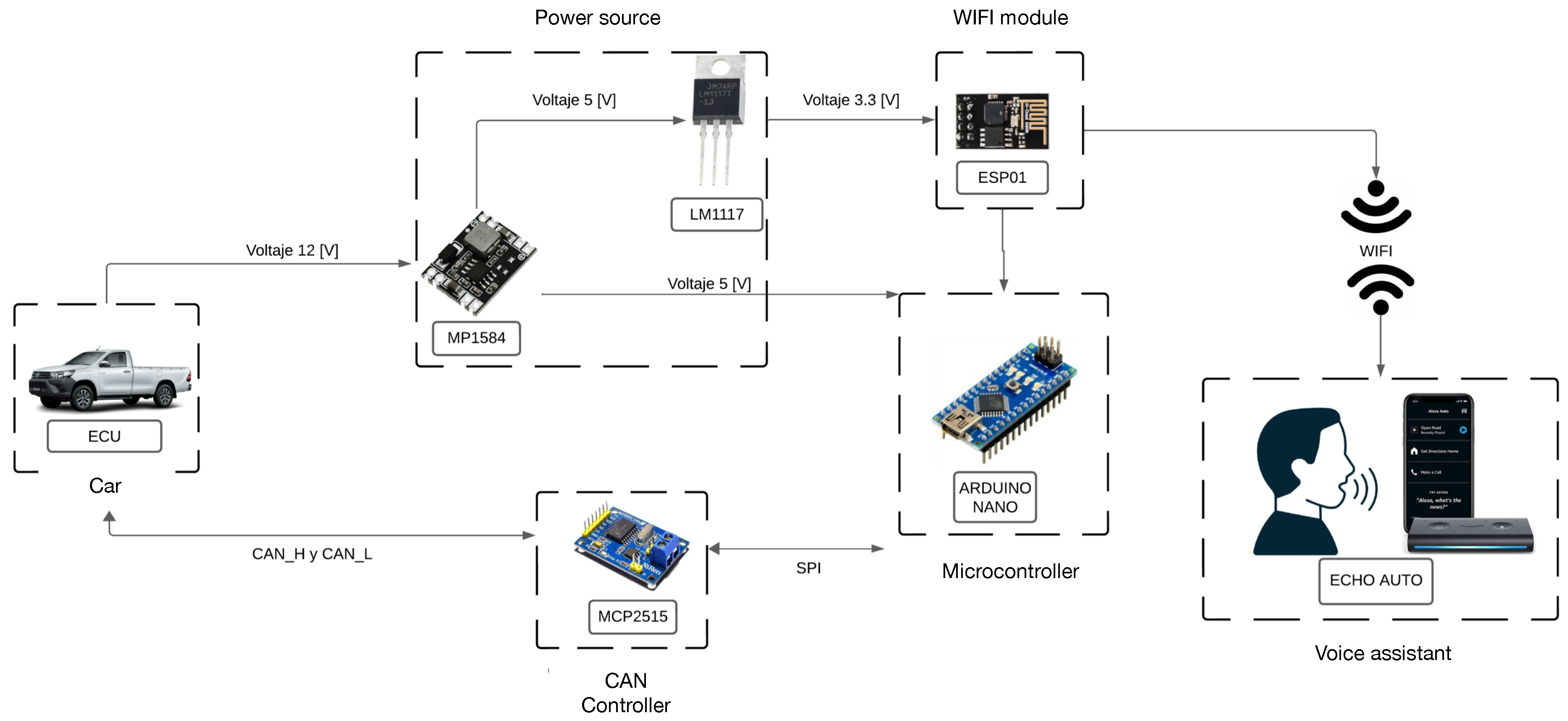
3. Materials and Methods
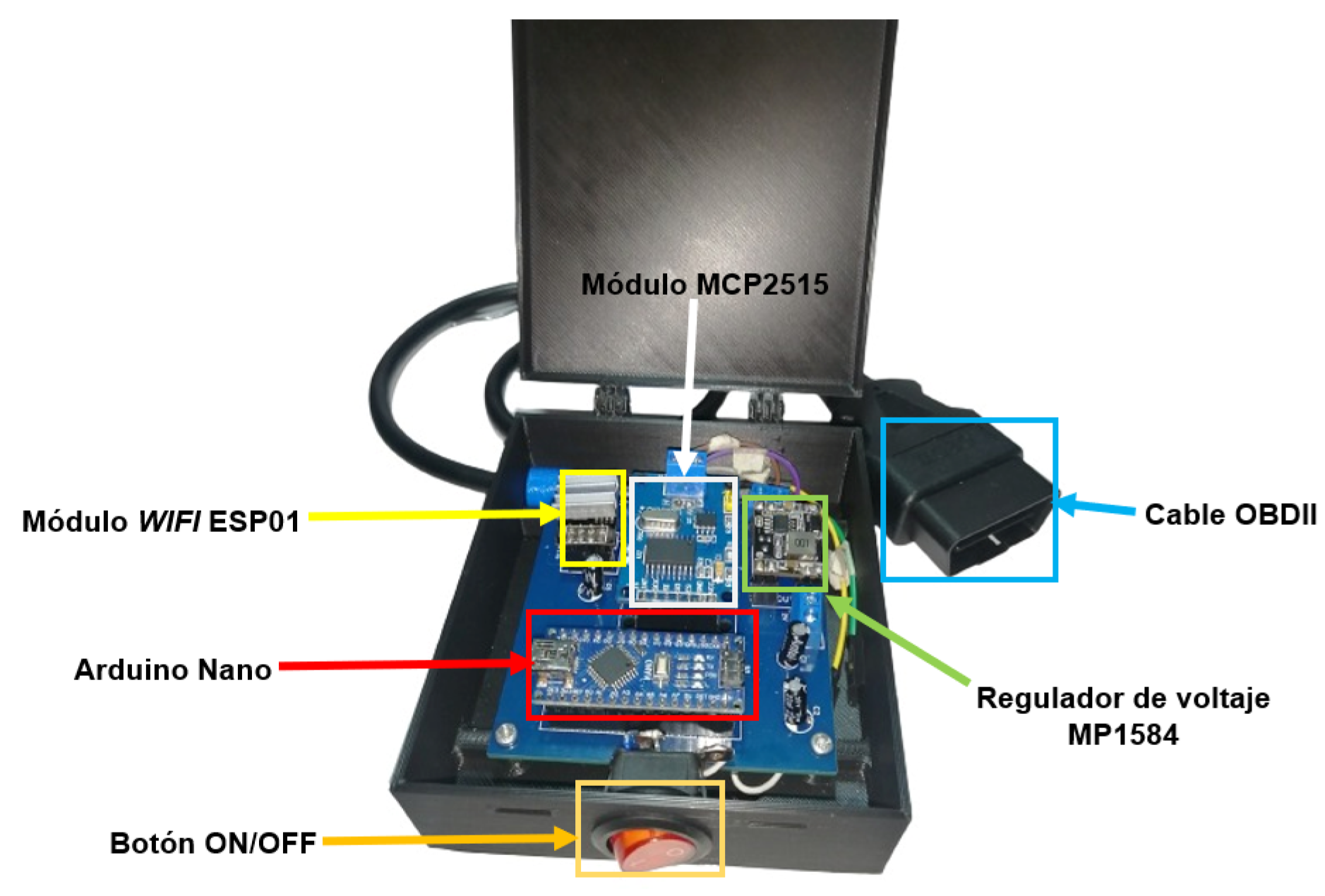
The primary objective of the proposed system is to integrate a vehicle with an Alexa Auto voice assistant. The key focus is on capturing vehicle data in real time and seamlessly transmitting it to a cloud server for efficient information management. Figure 1 illustrates the proposed connection framework for the devices and platforms utilized to accomplish this goal.

3.1. Hardware

Figure 2 shows the hardware components used for the link system between the vehicle’s computer and Alexa Auto, starting from the connection with the vehicle to the Wi-Fi communication with the voice assistant.
The proposed architecture incorporates a dual-stage power regulation subsystem: (1) a buck converter steps down the vehicle’s 12 VDC battery supply to 5 VDC for microcontroller operation, and (2) a secondary LDO regulator delivers 3.3 VDC for the Wi-Fi transceiver. An ATmega328P-based Arduino Nano microcontroller (Arduino AG, Turin, Italy) serves as the central processing unit, acquiring and preprocessing vehicular data through controller area network (CAN) bus protocols.
CAN bus communication is implemented via an MCP2515 (Microchip Technology Inc., Chandler, AZ, USA) controller interfaced through a serial peripheral interface (SPI) at 10 MHz. This IC handles frame formatting, bit timing synchronization, and differential signal generation compliant with [15] specifications (high-speed physical media attachment). Processed telemetry is routed to an ESP-01S Wi-Fi module (Ai-Thinker Technology Co., Ltd., Shenzhen, China) through asynchronous serial communication (UART, 115,200 baud) for cloud transmission to the Blynk IoT middleware.
User interaction occurs through an Echo Auto smart speaker (Amazon Lab126, Sunnyvale, CA, USA) utilizing a Bluetooth Low Energy (BLE) link to the Amazon Alexa mobile application. This establishes a bidirectional command pathway: voice requests → Alexa Voice Service → Blynk API → microcontroller → vehicular computer→ vehicular devices.

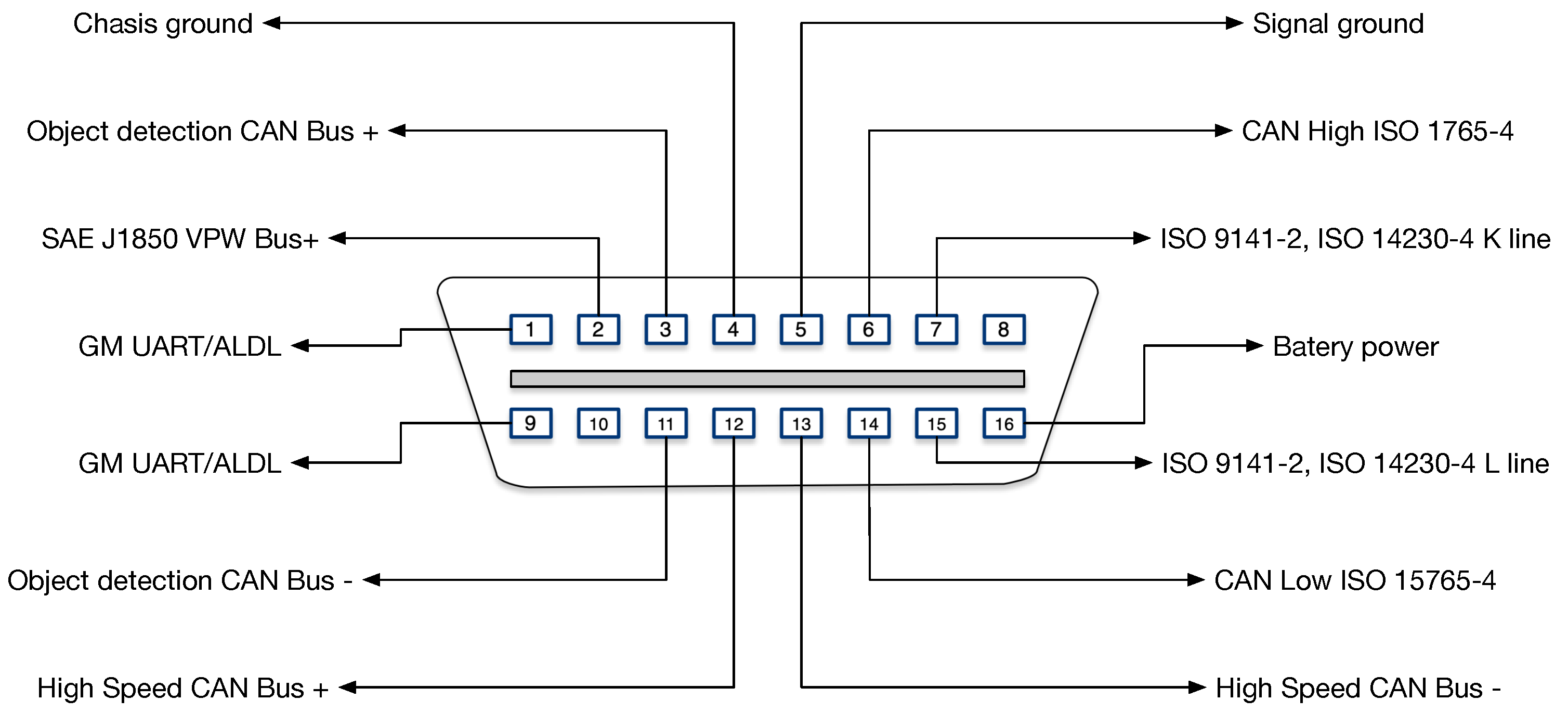
OBD-II Interface Implementation

Vehicular integration is achieved through the standardized [16]-compliant 16-pin diagnostic link connector (DLC). As illustrated in Figure 3 (type A configuration for 12 VDC systems), this interface provides direct access to the following:
  • CAN_H (Pin 6)/CAN_L (Pin 14) buses
  • Battery voltage (Pin 16)
  • Chassis ground (Pin 4)
The connector spatial placement follows [17] recommendations, typically residing within 600 mm of the steering column. System deployment confirmed compatibility across test platforms: Toyota Hilux and Mazda CX-3 (Japan).
Figure 3. OBDII A type for DLC interface [18].
Designs 09 00084 g003
A cable data extension is used for the DLC port, which allows the use of the necessary pins without hindering the driver of the vehicle. The implemented system is illustrated in Figure 4, which highlights the integration of all components and a box to protect the circuit.

3.2. Software

OBD-II is an onboard diagnostic system used in vehicles. It monitors key parameters related to the proper functioning of the engine, such as speed, engine load, coolant temperature, fuel consumption, ambient temperature, air flow, and gas emissions. If any of these critical parameters fall outside the established ranges, the OBD-II system stores and processes this information to notify the driver of a potential malfunction [18,19,20]. OBD-II systems can utilize one of five communication protocols, with each manufacturer choosing the most suitable one to implement in their vehicles. However, the CAN BUS protocol, defined by [21] CAN, is the most widely adopted and is even mandatory in certain regions. This protocol operates using pins 6 and 14 of the DLC to transmit a differential signal, while pins 4, 5, and 16 are used to supply power to diagnostic devices.
For data transmission, a CAN controller makes a transmission start request with a specific parameter identifier (PID), along with all the data in the message. When the bus is free, the data message is transmitted to all control units, which check the identifier and determine if the message is required; otherwise, they ignore it. This message is a sequence of bits with different parameters to identify them from start to finish and allow for communication between different units [20,22,23]. Figure 5 shows the standard message structure.
Functional addresses are used for a standard query or response on the vehicle CAN bus. This project uses the ID 0x7DF for a diagnostic query, which is sent to the ECU and gives its response on the ID 0x7E8. These specifications are defined in the SAE J1979 standard [24], as well as the structure that the message data field must have and the structure of the respective response. It should be noted that vehicles can have more than one CAN communication network; thus, the main modules of the vehicle are connected to a high-speed CAN bus (500 kbps), since a fast response is required from these modules because they are essential for the correct operation of the vehicle. Other modules such as climate control, doors, or windows have a lower priority, so they are connected to a lower-speed CAN bus (125 kbps) [23].

3.2.1. Variables to Be Monitored

The first vehicle used for the development of this system is a Toyota Hilux CS 2020 pickup truck form Japan, which works with the CAN communication protocol since its DLC connector identifies the use of pins 6 and 14 for CAN-H and CAN-L signals. Therefore, it is only possible to obtain vehicle status information through this port, while control actions are not possible since the respective modules are not connected to this CAN communication network. Additionally, the use of other pins in the DLC port is identified as shown in Figure 6, which are 4, 5, 6, 9, 12, 13, and 16. Pins 5 and 16 are used for the power supply of the developed system and the rest of the pins are not used since their use has another purpose that depends on the manufacturer.
To know the PIDs available in the Toyota truck’s computer, the hardware designed to make a request for PID 00 (hex) is used. This allows for displaying the PIDs compatible with the vehicle in a format of 4 bytes of data, where each of the bits that make up the response represents one of the following 32 PIDs established in the SAE J1979, specifying whether that PID is compatible or not. The request message sent to the CAN bus is 0x7DF020100, and the respective bytes are detailed in Table 1. Unlike the basic structure presented in Figure 5, only the 11-bit identifier and the data field are modified, since the rest of the message fields are automatically filled by software.
The response obtained is 0x7E8064100BE1FA813, and corresponds to the parameters specified in Table 2.
Using the bytes from the previous answer, we proceed to decode them into a total of 32 bits. With this data, it is possible to determine which PIDs are available or not in the hex range 0x01 to 0x20. Following this same methodology, we proceed to make two additional requests for PID 0x20 and PID 0x40 to find out what other parameters are available in the vehicle in the range of 0x21 to 0x40 and 0x41 to 0x60, respectively. With the responses obtained from these PIDs, all parameters that are compatible with the Toyota Hilux CS 2020 vehicle have been identified. Based on this information, the following variables are selected in Table 3, corresponding to several parameters available in the vehicle, which will allow one to know the specific information of its operation.
  • PID 03—Fuel System Status
PID 03 outputs two data bytes in response: the first byte describes the vehicle’s primary fuel system and the second one gives information about secondary fuel systems if they exist. The data values that each byte can take are described in Table 4.
Under normal conditions and when the car is running, the value to be obtained is 2.
  • PID 05—Engine Coolant Temperature
The measurement of this variable is used for the vehicle’s computer to calculate the air/fuel mixture. As specified in [25,26], the coolant temperature should be between 85 °C and 95 °C when the engine is at full load and between 95 °C and 110 °C at a partial load for a 1.6 L engine. It should be noted that these ranges may vary depending on the engine. The response of the PID 05 request has 1 byte of data, which, when transformed to decimal number, can represent a temperature range between −40 °C and 215 °C.
  • PID 0E—Advance Time
The advance timing or ignition advance corresponds to the time at which the air–fuel mixture must be ignited to achieve maximum combustion pressure after the top dead point (TDC sensor) is reached. For this purpose, ignition must occur at a crankshaft rotation angle of approximately 5° to 10° before the top dead point (PMS). This range will depend on the physical characteristics of the engine and the engine speed [27]. The PID 0E request gives, as a response, 1 byte of data, with which a range between −64° and 63.5° before PMS can be described. For this case, a range between 0° and 25° is considered as a normal as suggested in [27] based on tests performed for different vehicle models.
  • PID 24—Oxygen sensor
The oxygen sensor makes it possible to determine the composition of the exhaust gases by measuring the oxygen concentration in the exhaust pipe. The signal provided by this sensor is used to determine the optimum air–fuel ratio. Depending on the value of the ratio, it can be determined whether a mixture is rich or lean. If there is more air than fuel in the mixture, it is considered a lean mixture, and if there is more fuel than air, the mixture is considered rich [28].
The PID 24 request gives 4 bytes of data as a response; the first 2 bytes A and B are used for the calculation of the air–fuel equivalence ratio, called lambda ( λ ). According to SAE J1979 specifications, the values that λ can take are between 0 and less than 2. λ > 1 indicates a lean mixture, and if λ < 1, the mixture is rich. And, when λ = 1, the air–fuel ratio (AFR) is considered as exactly the one needed for an efficient combustion, referred to as a stoichiometric mixture. In the case of gasoline engines, this air–fuel ratio is 14.7:1 [28]. Thus, in order to determine the air–fuel ratio (AFR), the starting point is as follows:
λ = A F R A F R e s q u e t i m e t r i c
where, we obtain:
A F R = λ × A F R e s q u e t i m e t r i c = λ × 14.7
AFR values lower than 14.7 indicate a rich mixture and higher values indicate a lean mixture. Depending on the engine operation, the AFR value may vary; however, as explained in [28], when there is a moderate load and acceleration, the ratio should be close to the stoichiometric ratio (AFR = 14.7:1), if there is a higher load or maximum power, this ratio can reach up to AFR = 13:1, and, otherwise, if the load and acceleration is low, the ratio can be up to AFR = 16:1. Higher or lower values in this range may indicate that there is a problem in the operation of the vehicle.

3.2.2. Actuator Selection

Due to the fact that, in the first vehicle used, it was not possible to control actions such as climate control, door, or glass locking, among others, a second alternative was used that does allow it. The vehicle used is a Mazda CX-3 SUV (2021). Pins 3, 4, 5, 6, 8, 11, 14, 15, and 16 are enabled in the ODBII port; that is, the vehicle has two CAN buses, one high-speed bus (500 kbps) that uses pins 6 and 14, and another lower-speed bus (125 kbps) that uses pins 3 and 11. This allows access to the vehicle status parameters and some actuators that are connected to the ECU through this additional bus. Similarly, pins 5 and 16 are used for the power supply of the developed system, and the rest of the pins are not used.
For the developed system, the lower-speed CAN bus with pins 3 and 11 is used to control the activation or deactivation of the vehicle’s door lock. To achieve this goal, or even take control over other functions, it is necessary to know the CAN message to be sent to the communication bus so that the respective module performs the desired action.
The process for identifying the CAN messages that are related to the activation of certain actuators is performed by reverse engineering; that is to say, an actuator of the vehicle is activated manually and, with the help of the designed hardware, the new data packets that are displayed are verified on the screen. By repeating this process several times, it is possible to identify the CAN message that is related to the activation of a specific actuator. This process is necessary since there is no official information or documentation that specifies the CAN packets that are associated with the different actuators of the vehicle.
Following this process, CAN messages related to the activation and deactivation of the vehicle’s door locks are identified as follows:
  • The following message, which is associated with the module PID 7B7, is used to deactivate or unlock doors in block 02 and the first frame. The complete message is 0x7B70201400000000001.
  • A message addressed to the same address or PID is used for the activation or locking of doors, changing the bits that correspond to the activation of the respective actuator. The complete message is 0x7B702012011000000000D1.
As part of a user forum for Mazda CX-3, ref. [29] has developed an Excel template where most of the CAN messages for this brand have been decoded. This was very useful for determining the general structure of the messages obtained and verifying that they are correct. Table 5 shows the structure for the CAN messages identified.
In this type of message, each bit of the data bytes is assigned or related to a specific function of the vehicle. Due to the limited information or official data, the function of most of them is unknown, so it is not recommended to modify this data without being sure of its function.

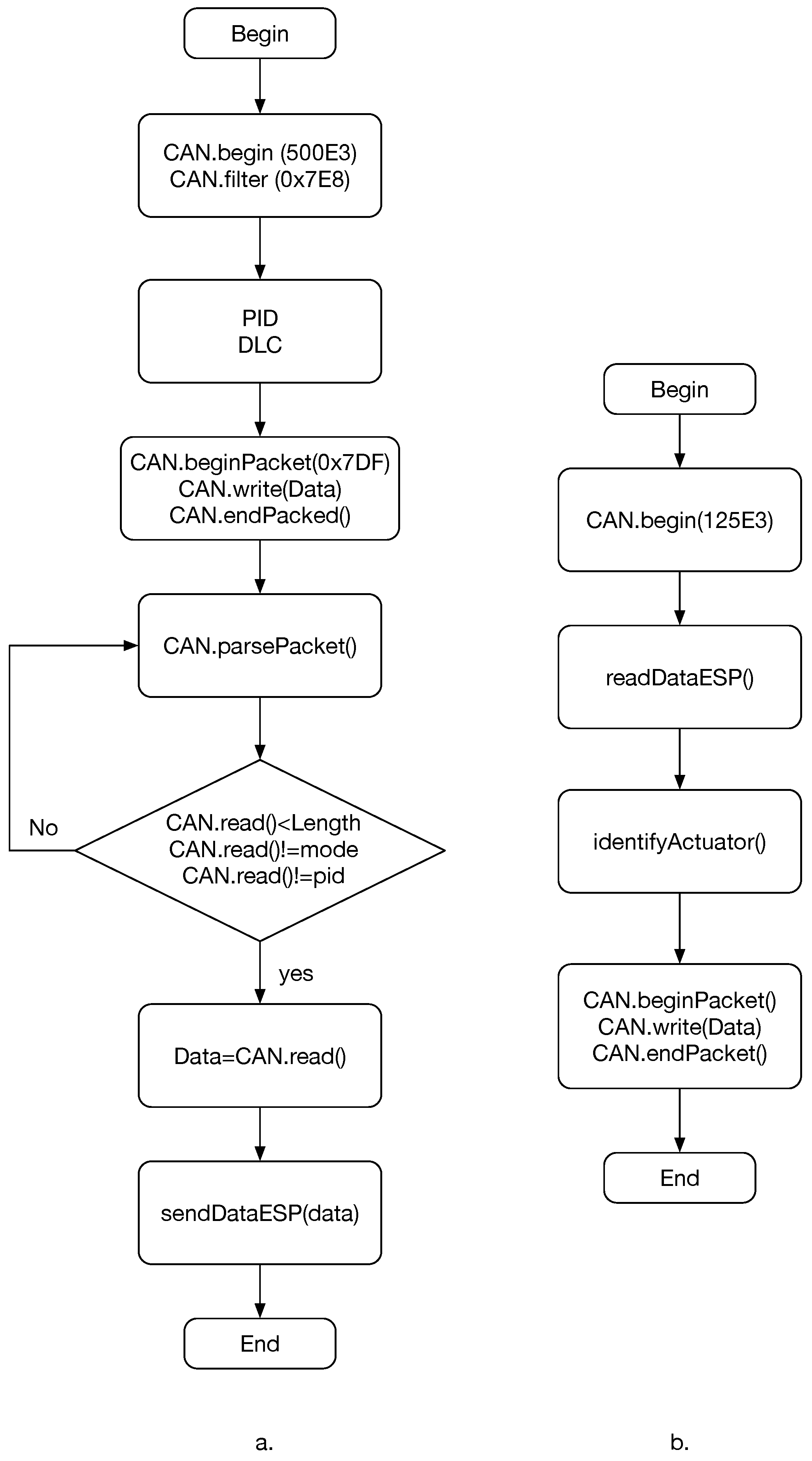
3.2.3. Arduino Nano Programming

Once the CAN messages and the structure that they have are determined in order to obtain the vehicle information, Figure 7 shows the general flowcharts describing the program made for the Arduino Nano board.
Figure 7a describes the program used to read the selected parameter information from the Toyota CS truck. In this process, information requests for each of the required parameters are sent to the CAN bus. Once the response is obtained, it is verified that it is the correct one and the respective data is sent to the ESP01 board through the serial port. This is performed continuously every 500 ms so that the user has updated information about their vehicle.
Figure 7b describes the program used to activate or deactivate the door locks in Mazda CX-3, for which it is necessary that the user has requested the voice assistant to activate the locks. With this information, the message related to the requested action is sent to the CAN bus.
It should be noted that the same hardware is used to connect the two vehicles; however, the pins used in the DLC port of each one must be changed, since, for the Toyota vehicle, pins 6 and 14 are needed to connect to the high-speed CAN bus (500 kbps), while, for the Mazda vehicle, pins 3 and 11 are used, which corresponds to the lower-speed CAN bus (125 kbps).

3.2.4. ESP01 Board Programming

The ESP01 board is used to send or receive data via Wi-Fi from the Blynk IoT platform. Figure 8 describes the two programs to be loaded on the board, either to send vehicle information to the Blynk platform or to receive an activation command from the Blynk platform.
Figure 8a describes the program designed to read data from the serial port of the Arduino Nano board. This data is conditioned and loaded into the Blynk platform in virtual variables for each of the monitored parameters. In this way, the user will always have updated information of their vehicle in the platform.
Figure 8b describes the program designed to continuously monitor the virtual variables in the Blynk platform related to the activation or deactivation of the vehicle’s door lock. Once the BLYNK_WRITE(V0) function indicates a change in a virtual variable, this data is sent to the Arduino Nano board through the serial port. This change in the state of the variable results from a voice command given by the user to the skill developed for Alexa.

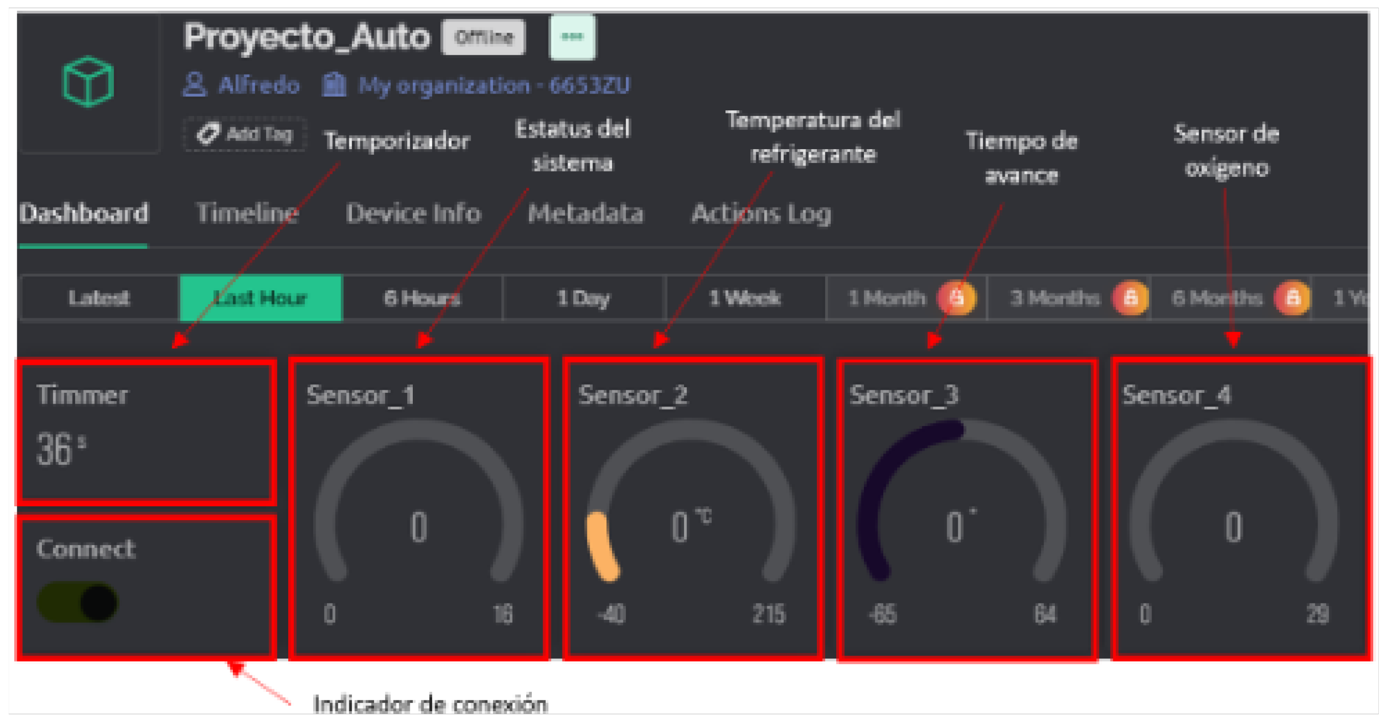
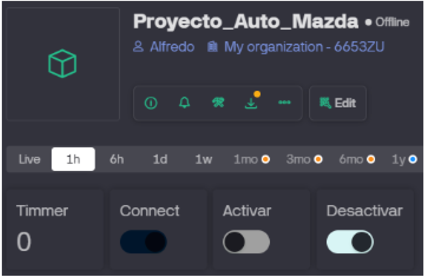
3.2.5. Car Variables on Blynk Platform
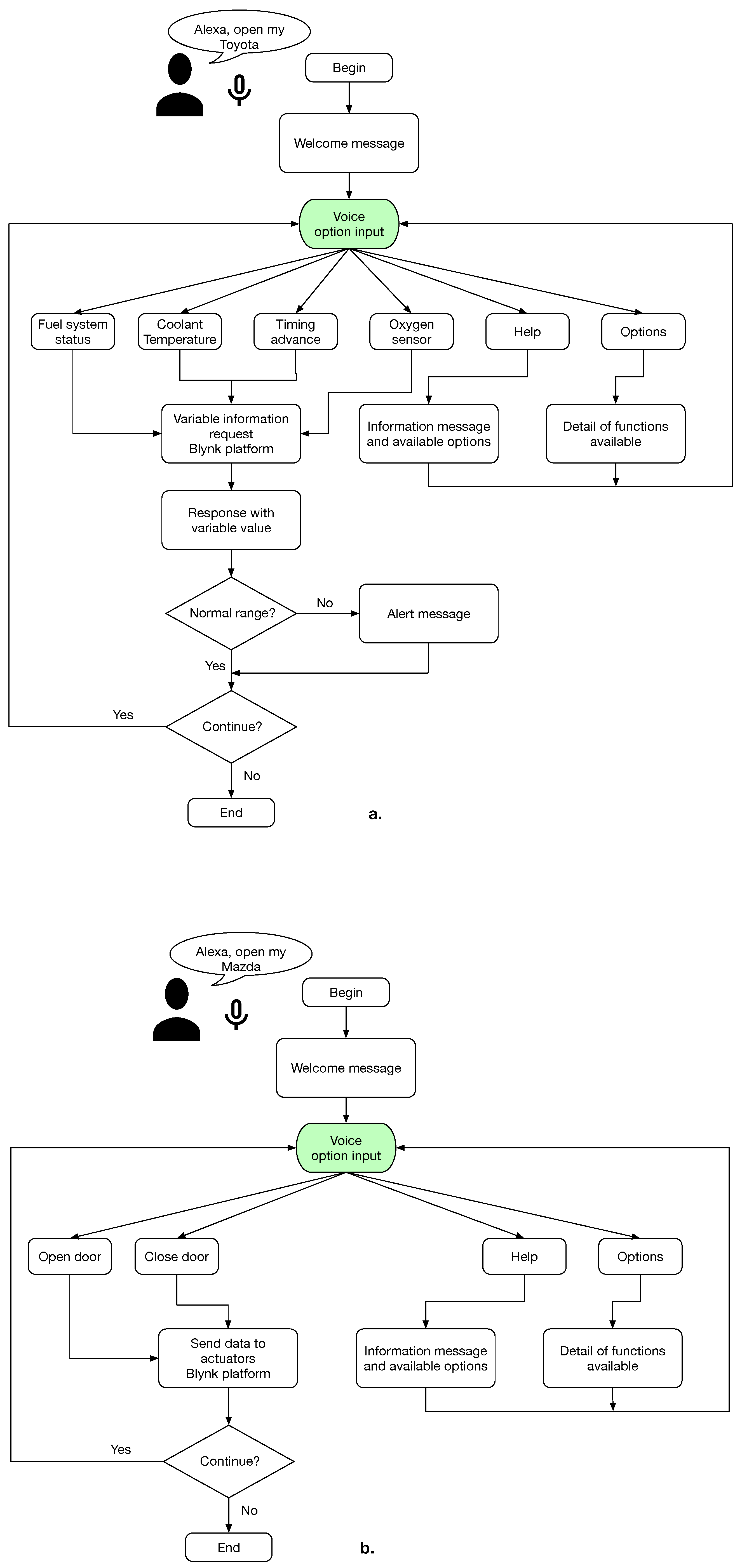
Once the ESP01 board has been connected to the platform, we proceed to create a control panel with each of the selected variables. The first variable is a timer that indicates the time in seconds elapsed since the connection of the device to the IoT platform. The second variable indicates that the connection of the Wi-Fi module to the platform has been established. The remaining four variables represent the values coming from the vehicle sensors with their set ranges.
Figure 9 shows the Blynk interface with the selected variables so that the user can constantly monitor their status.
To control the doors locking and unlocking, a similar interface is made with the respective variables; this interface is shown in Figure 10. The state of the virtual variables used will change once the user makes the relevant request.

3.2.6. Alexa Skill

The Voiceflow platform is used to program the voice applications that will be used with the Alexa voice assistant.
The diagram in Figure 11a describes the programming, in Voiceflow, for reading the variables of the selected sensors. In this case, the skill activation phrase is “Alexa, open my Toyota”, with which, the conversation will start, where the assistant will ask the user for the variable that they want to know, and, depending on their selection, the assistant will connect to the Blynk platform and obtain the value of the requested variable to give as an answer.
Once Alexa has said the value of the variable, a check is made to know if this value is within the normal range; otherwise, an alert message is given to the user. If everything is in order, the user is asked if they want any additional information or not. If the answer is yes, the user can choose another variable, and if they do not want more information, the conversation ends.
The program represented in the diagram in Figure 11b is similar to that of the sensor reading; however, instead of sending a request for information to the Blynk platform, a data update is performed on the respective variables. This allows the user to select the options for enabling or disabling the Mazda CX-3 door lock.
In case the user does not know how the skills work, there are two alternatives: the first one is the “Help” option, where the purpose of the skill and its functionalities will be explained. The second alternative is the “Options” option, which will simply remind the user which functionalities can be selected.

4. Test and Results

The skill’s function tests are focused on the reading of sensors and the activation of the actuator in the respective vehicle in order to evaluate that the values given to the user are correct and that the control of the door locks is achieved.

4.1. Functional Tests of the Sensor Reading Skill

These tests were carried out based on the requests programmed in the skill, which refer to each of the selected variables of the Toyota Hilux CS 2020 vehicle. Each of the recorded values were checked by means of the ELM327 commercial device (OBDLink EX, ScanTool.net LLC, Portland, OR, USA). This device is connected to the vehicle at the same time as the prototype developed in this project by means of a duplex OBDII cable.

4.1.1. Sensor Read Test with the Vehicle Stopped

The aim is to determine the ability of the Echo Auto to respond in situations with little or no noise in the environment. For each case, a total of 10 tests are considered for each of the available interactions. To perform this test, the following considerations are taken into account during the test performed.
  • The engine is on, but the vehicle is not running.
  • The ambient noise is approximately 61 dB.
  • The revolutions per minute is 656 rpm.
  • The car is in a neutral position.
  • The accelerator is not being pressed.
Following these considerations, the values of each selected sensor are recorded.
  • Fuel system status
Table 6 presents the results obtained from the fuel status reading with the engine running. The experimental results demonstrate complete agreement between the dataset generated by the proposed system and the reference measurements acquired through commercial scanning equipment, with no observable deviation.
  • Coolant temperature
The recorded temperature values (Celsius degrees) are presented in Table 7, where the experimental results demonstrate complete agreement between the dataset generated by the proposed system and the reference measurements acquired through commercial scanning equipment, with no observable deviation. The engine was kept running for approximately 10 min so that the temperature was raised to approximately 45 °C. Each engine coolant temperature data point was recorded at 2 min intervals and represents the average of five consecutive measurements.
  • Timing advance
The results of the timing advance are shown in Table 8, where the experimental results demonstrate complete agreement between the dataset generated by the proposed system and the reference measurements acquired through commercial scanning equipment, with 3.11% deviation. The minor variance arises due to nonsimultaneous data collection from the two systems, whereas an FPGA-enabled setup would permit truly concurrent measurements.
  • Oxygen sensor
In Table 9, the air–fuel ratio (AFR) values obtained from the oxygen sensor are recorded. Each AFR data point was recorded at 2 min intervals and represents the average of five consecutive measurements. The experimental results demonstrate complete agreement between the dataset generated by the proposed system and the reference measurements acquired through commercial scanning equipment, with 0.036% deviation. The minor variance arises due to nonsimultaneous data collection from the two systems, whereas an FPGA-enabled setup would permit truly concurrent measurements.
During this test, it was observed that the pronunciation of lengthy commands can lead to the Echo Auto failing to capture the audio accurately, resulting in an incorrect or absent response. Additionally, for variables such as ignition timing or the air–fuel ratio (AFR), the values provided by the skill exhibit a higher margin of error compared to those recorded by the OBDLink EX device. This discrepancy is primarily attributed to the rapid fluctuations in these variables over time, coupled with the fact that the two systems do not capture the data at precisely the same moment, leading to minor variations in the readings.

4.1.2. Sensor Read Test with the Vehicle Running

In this case, there is a considerable difference in the noise inside the vehicle. Likewise, a total of five tests for each of the available interactions have been considered for recording the sensor data. To carry out this test, the following considerations are taken into account:
  • The engine is on and the vehicle is running.
  • The windows are closed.
  • The ambient noise is approximately 63 dB.
  • The vehicle is at an average speed of 30–40 km/h.
Under these conditions, we proceed to record the variables of the sensors and compare them with those provided by the OBDLink EX scanner.
  • Fuel system status
Table 10 presents the results obtained from the fuel status reading with the vehicle in motion. The experimental results demonstrate complete agreement between the dataset generated by the proposed system and the reference measurements acquired through the ODBLink EX device, with no observable deviation.
  • Coolant temperature
The coolant temperature values (Celsius degrees) are presented in Table 11, where the experimental results demonstrate complete agreement between the dataset generated by the proposed system and the reference measurements acquired through commercial scanning equipment, with no observable deviation. When running, the temperature values have risen considerably, but remain within normal ranges. Each engine coolant temperature data point was recorded at 5 min intervals and represents the average of five consecutive measurements.
  • Timing advance
Table 12 shows the results of reading the data of the timing advance, where the experimental results demonstrate complete agreement between the dataset generated by the proposed system and the reference measurements acquired through commercial scanning equipment, with 3.11% deviation. The minor variance arises due to nonsimultaneous data collection from the two systems, whereas an FPGA-enabled setup would permit truly concurrent measurements.
  • Oxygen sensor
In Table 13, the air–fuel ratio (AFR) values obtained from the oxygen sensor with the vehicle in motion are recorded. In this specific case, as the vehicle is in motion, these values vary according to the conditions under which the vehicle is being driven, such as the speed or vehicle load. Each AFR data point was recorded at 5 min intervals and represents the average of five consecutive measurements. The minor variance arises due to nonsimultaneous data collection from the two systems, whereas an FPGA-enabled setup would permit truly concurrent measurements.
The errors presented in the sensor reading tests with the vehicle in motion are less than 2%, but it is important to consider that there are multiple factors external to the circuit that can affect the response given. These factors can come from the vehicle, such as speed, load, acceleration, and other physical characteristics while driving, as well as external factors to the vehicle, such as the Internet connection of the Wi-Fi module and the Bluetooth link between the mobile device and the Echo Auto, which can affect the performance of the device. However, the results recorded for each variable do not present significant errors.

4.2. Skill Test for Locking/Unlocking Door

The following conditions with respect to the condition of the vehicle (Mazda CX-3 SUV, Hiroshima, Japan) and the environment have been considered for the actuator function tests:
  • The engine is on, but the vehicle is not running.
  • The approximate ambient noise is 50 dB.
  • The revolutions per minute is 750 rpm.
  • The vehicle is in parking mode.
  • The accelerator is not being pressed.
In these conditions, Table 14 shows the results regarding the fulfillment of the requested command, either to activate or deactivate the vehicle’s door lock.
System Response Efficiency: Experimental trials demonstrated 85% command execution efficiency in the parked vehicle scenario. The observed 15% error rate primarily stemmed from voice recognition failures for phonetically similar lock/unlock commands (e.g., “Alexa lock the door” vs. “Alexa unlock the door”). Contributing factors include the following:
  • Lexical ambiguity: Minimal phonetic differentiation between critical verbs (“lock”/“unlock”);
  • Environmental noise: Background interference during command utterance;
  • User articulation variability: Non-uniform pronunciation across test participants.
Safety-constrained implementation: Door control functionality was deliberately restricted to parked states in alignment with vehicular safety protocols (ISO 26262). This design prevents unintended actuation during motion, addressing risks of accidental door operation while driving.

5. Conclusions

This research introduced an innovative system enabling seamless interfacing between Alexa Auto and a vehicle’s onboard computer, significantly enhancing Alexa’s capabilities through direct access to sensor data and the control of actuators (e.g., door locks). The hardware interfaces with the vehicle’s OBD-II port and CAN communication network, facilitating the real-time reading and writing of vehicle variables. Implemented in a Toyota Hilux and Mazda CX-3, the system unlocks opportunities to improve passenger comfort and preemptively detect engine issues.
However, standardization remains a critical challenge. Despite OBD-II and CAN being industry standards, vehicle-specific variations in accessible PIDs (parameter identifiers) and non-uniform memory addressing hinder universal compatibility. This complicates creating a one-size-fits-all solution for Alexa—or future voice assistants—to interface with arbitrary vehicles.

Performance Validation Revealed High Accuracy

Sensor Data: Variable readings showed a ≤4% error versus the OBDLink EX reference when stationary, improving to <2% during motion. Minor discrepancies stemmed from rapid fluctuations (e.g., ignition timing) and timing offsets in data acquisition.
Actuator Control: Voice command recognition achieved 85% success in the Mazda CX-3, though hardware/software restrictions limited actuator control to specific conditions.
Looking ahead, future work will focus on leveraging AI to interpret sensor data for predictive maintenance diagnostics. Addressing vehicle-specific constraints and advocating for industry-wide PID standardization will be essential for scaling this technology. The system marks a pivotal step toward intelligent, voice-integrated vehicular ecosystems, balancing innovation with pragmatic adaptability.

Author Contributions

Methodology: J.P.A.T.; Software: K.S.C. and A.L.B.; Validation: K.S.C.; Formal analysis: J.P.A.T., A.I.J. and D.A.A.; Investigation: K.S.C. and A.L.B.; Data curation: K.S.C.; Writing—original draft: A.L.B.; Writing—review and editing: A.I.J. and D.A.A.; Supervision: J.P.A.T. All authors have read and agreed to the published version of the manuscript.

Funding

This research received no external funding.

Data Availability Statement

https://repositorio.espe.edu.ec/search?spc.page=6&query=cer (accessed on 15 April 2025), Desarrollo de un sistema de enlace entre la computadora de un vehículo y Alexa Auto.

Conflicts of Interest

The authors declare no conflicts of interest.

References

  1. Williams, K.J.; Peters, J.C.; Breazeal, C.L. Towards leveraging the driver’s mobile device for an intelligent, sociable in-car robotic assistant. In Proceedings of the 2013 IEEE Intelligent Vehicles Symposium (IV), Gold Coast, QLD, Australia, 23–26 June 2013; pp. 369–376. [Google Scholar] [CrossRef]
  2. Gonzalez, P. LOS COCHES QUE MEJOR… TE HABLAN. Tecnologia HC: Madrid, Spain, 2022. Available online: https://hackercar.com/los-coches-que-mejor-te-hablan/ (accessed on 15 April 2025).
  3. Surface Vehicle Standard—OBD II Scan Tool; SAE International: Warrendale, PA, USA, 2014.
  4. Road Vehicles—Communication Between Vehicle and External Equipment for Emissions-Related Diagnostics, 5th ed.; International Organization for Standardization: Geneva, Switzerland, 2020.
  5. Katreddi, S.; Kasani, S.; Thiruvengadam, A. A Review of Applications of Artificial Intelligence in Heavy Duty Trucks. Energies 2022, 15, 7457. [Google Scholar] [CrossRef]
  6. Braun, M.; Mainz, A.; Chadowitz, R.; Pfleging, B.; Alt, F. At Your Service: Designing Voice Assistant Personalities to Improve Automotive User Interfaces. In Proceedings of the 2019 CHI Conference on Human Factors in Computing Systems (CHI ’19), Glasgow, UK, 4–9 May 2019; pp. 1–11. [Google Scholar] [CrossRef]
  7. Tobisch, V.; Funk, M.; Emfield, A. Dealing with Input Uncertainty in Automotive Voice Assistants. In Proceedings of the 12th International Conference on Automotive User Interfaces and Interactive Vehicular Applications (AutomotiveUI ’20), Virtual, 21–22 September 2020; pp. 161–168. [Google Scholar] [CrossRef]
  8. Damaj, I.W.; Yousafzai, J.K.; Mouftah, H.T. Future Trends in Connected and Autonomous Vehicles: Enabling Communications and Processing Technologies. IEEE Access 2022, 10, 42334–42345. [Google Scholar] [CrossRef]
  9. Reséndiz, M. Sistema Inteligente de Monitoreo y Caracterización de Gases Generados por Vehículos Operados Bajo Diferentes Modos de Manejo. Master’s Thesis, Universidad Autónoma de Querétaro, Santiago de Querétaro, Mexico, 2024. [Google Scholar]
  10. Calleja Lecanda, J. Aplicación de Asistente Virtual para la Búsqueda de Aparcamiento en Ciudades Inteligentes. Bachelors’s Thesis, Universidad de Cantabria, Cantabria, España, 2021. [Google Scholar]
  11. Bodero Jiménez, J.; Wong Caicedo, K. Diseño e Implementación de un Sistema de Conectividad para el Monitoreo en Tiempo Real de los Sistemas Funcionales de un Automóvil. Ph.D. Thesis, Universidad Politécnica Salesiana, Quito, Ecuador, 2021. [Google Scholar]
  12. Zhou, X.; Zheng, Y. Research on Personality Traits of In-Vehicle Intelligent Voice Assistants to Enhance Driving Experience. In Proceedings of the HCI in Mobility, Transport, and Automotive Systems, Copenhagen, Denmark, 23–28 July 2023; Krömker, H., Ed.; Springer: Cham, Switzerland, 2023; pp. 236–244. [Google Scholar]
  13. Ramírez Grajales, M. Asistentes de voz se Perfilan Como Aliados de la Revolución Automotriz. FORBES. 2021. Available online: https://forbes.com.mx/forbes-life/auto-asistentes-de-voz-aliados-revolucion-automotriz/ (accessed on 17 April 2025).
  14. Hernández Mejía, R. La Prealimentación Como Técnica de Diseño de Experiencia de Usuario Aplicada a Indicadores Vitales Propios de un Panel de Instrumentos Automotriz Manejado por Asistente Virtual. Ph.D. Thesis, CIATEQ A.C., Santiago de Querétaro, México, 2023. [Google Scholar]
  15. Road Vehicles—Controller Area Network (CAN)—Part 2: High-Speed Medium Access Unit; International Organization for Standardization: Geneva, Switzerland, 2016.
  16. Diagnostic Connector—Equivalent to ISO/DIS 15031-3; SAE International: Warrendale, PA, USA, 2012.
  17. Battery Test Guide for 12V Automotive Starting, Lighting, and Ignition Systems; SAE International: Warrendale, PA, USA, 2020.
  18. Duan, J.; Xiao, J.; Zhang, M. Framework of CANopen Protocol for a Hybrid Electric Vehicle. In Proceedings of the 2007 IEEE Intelligent Vehicles Symposium, Istanbul, Turkey, 13–15 June 2007; pp. 906–911. [Google Scholar] [CrossRef]
  19. Andrade, R.d.; Santos, M.M.D.; Justo, J.F.; Yoshioka, L.R.; Hof, H.J.; Kleinschmidt, J.H. Security architecture for automotive communication networks with CAN FD. Comput. Secur. 2023, 129, 103203. [Google Scholar] [CrossRef]
  20. Kumar, B.; Ramesh, J. Improved Automotive CAN Protocol Based on Payload Reduction and Selective Bit Stuffing. Circuits Syst. 2016, 7, 3415–3429. [Google Scholar] [CrossRef]
  21. Road Vehicles—Diagnostic Communication over Controller Area Network (DoCAN)—Part 4: Requirements for Emissions-Related Systems, 3rd ed.; International Organization for Standardization: Geneva, Switzerland, 2021.
  22. Woo, S.; Jo, H.J.; Lee, D.H. A Practical Wireless Attack on the Connected Car and Security Protocol for In-Vehicle CAN. IEEE Trans. Intell. Transp. Syst. 2015, 16, 993–1006. [Google Scholar] [CrossRef]
  23. Sánchez Vela, L.; Molano Clemente, M.; Fabela Gallegos, M.; Martínez Madrid, M.; Hernánez, J.; Vázquez Vega, D.; Flores Centeno, O. Revisión Documental del Protocolo CAN Como Herramienta de Comunicación y Aplicación en Vehículos; Instituto Mexicano del Transporte, Ed.; Secretaria de Comunicaciones y Transporte: Sanfandila, Qro, 2016; Available online: https://imt.mx/archivos/Publicaciones/PublicacionTecnica/pt474.pdf (accessed on 10 April 2025).
  24. Jung, D.H.; Jeong, G.M.; Ahn, H.S.; Ryu, M.; Tomizuka, M. Remote Diagnostic Protocol and System for U-Car. In Proceedings of the Ubiquitous Convergence Technology, Jeju Island, Republic of Korea, 5–6 December 2006; Stajano, F., Kim, H.J., Chae, J.S., Kim, S.D., Eds.; Springer: Berlin/Heidelberg, Germany, 2007; pp. 60–68. [Google Scholar]
  25. Bencs, P.; Alktranee, M. The potential of vehicle cooling systems. J. Phys. Conf. Ser. 2021, 1935, 012012. [Google Scholar] [CrossRef]
  26. González Calleja, D. Mantenimiento de Sistemas de Refrigeración y Lubricación de los Motores Térmicos; Paraninfo, Ed.; Artedis: Madrid, Spain, 2015; e-book: 9788428352048. [Google Scholar]
  27. Madriz Meza, F. Módulo de Control de Avance de Encendido. Ph.D. Thesis, Instituto Tecnológico de Costa Rica, Cartago, Costa Rica, 2004. [Google Scholar]
  28. Díaz, E. Sensores y actuadores en el sistema de admisión y escape con equipos de diagnóstico automotriz. Cotopaxi Tech 2022, 2, 66–78. [Google Scholar]
  29. Litnevskyi, S. Manual de Usuario de Excel Mazda SkyActiv OBD-II calc (FORScan). FORScan Forum. 2021. Available online: https://www.forscan.org/forum/viewtopic.php?t=3379 (accessed on 15 April 2025).
Figure 1. Interconnection of Alexa Auto and vehicle’s computer.
Designs 09 00084 g001
Figure 2. Hardware for interconnection between Alexa Auto and vehicle’s computer.
Designs 09 00084 g002
Figure 4. Dispositive developed.
Designs 09 00084 g004
Figure 5. CAN bus structure.
Designs 09 00084 g005
Figure 6. ODBII port.
Designs 09 00084 g006
Figure 7. Flow diagrams: (a) request PID information and (b) send CAN messages.
Designs 09 00084 g007
Figure 8. Flow diagrams: (a) ESP01 serial port reads and sends the message to Blynk; (b) virtual variables change monitoring.
Designs 09 00084 g008
Figure 9. Vehicle variables display panel.
Designs 09 00084 g009
Figure 10. Vehicle variables display panel for locking or unlocking the doors.
Designs 09 00084 g010
Figure 11. Flowchart of the skill designed (a) for the reading of sensor variables of the Toyota Hilux CS 2020 vehicle and (b) for the activation of locks of the Mazda CX-3 vehicle.
Designs 09 00084 g011
Table 1. PID request—show PID.
Identifier (11 Bits, Request)Data Bytes
Number of bytes of
additional data
Service
(01 = show data)
PID code
(00 = show PIDs)
No used
(ISO 15765-2)
7DF020100
Table 2. PID reply—show PID.
Identifier (11 Bits, Reply)Data Bytes
Number of
bytes of
additional data
Request Service,
add 40 h
PID code
(00 = show PIDs)
Byte data
0
Byte data
1
Byte data
2
Byte data
3
No used
(ISO 15765-2)
7E8064100BE1FA813
Table 3. Variables and PIDs for vehicle for monitoring.
PIDDescriptionMinMaxEquationUnits
03Fuel status system---Table 4
05Coolant engine’s temperature−40215A-40 ° C
0EAdvance time−6463.5 A 2 64 Before
24 0 2 Sensor (fuel–air ratio) λ 0<2 2 65536 256 A + B Ratio
Note: A and B are the data bytes obtained from the vehicle response.
Table 4. Fuel system status.
ValueStatus
0Engine OFF
1Circuit open, low engine’s temperature
2Circuit close, use oxygen sensor for fuel mix
4Circuit open, high engine load or fuel outage due to slowdown
8Circuit open, fail system
16Circuit close, oxygen sensor used but there is a feedback system fault
Table 5. CAN messages structure for Mazda cars.
IDBloqMessageData BytesCheck SUM
07B702014000000001
Table 6. Fuel system status, vehicle stop.
Test12345678910
Car status with Alexa system2222222222
OBDLink EX device2222222222
error0%0%0%0%0%0%0%0%0%0%
Table 7. Coolant temperature, vehicle stop.
Test12345
Coolant temperature with Alexa system4545454646
OBDLink EX device4545454646
error0%0%0%0%0%
Table 8. Timing advance, vehicle stop.
Test12345678910
Timing advance with Alexa system10101011101010111010
OBDLink EX device9101010101010101010
error11.11%0%0%10%0%0%0%10%0%0%
Table 9. AFR, vehicle stop.
Test12345
Oxygen sensor with Alexa system14.7214.7514.7314.7114.75
OBDLink EX device14.7214.7614.7314.7214.76
error0%0.06%0%0.06%0.06%
Table 10. Fuel system status, vehicle running.
Test12345678910
Car status whith Alexa system2222222222
OBDLink EX device2222222222
error0%0%0%0%0%0%0%0%0%0%
Table 11. Coolant temperature, vehicle running.
Test12345
Coolant temperature with Alexa system8181808181
OBDLink EX device8180808081
error0%1.25%0%1.25%0%
Table 12. Timing advance, vehicle running.
Test12345678910
Timing advance with Alexa system29413742424042384240
OBDLink EX device30403742414041384241
error3.33%2.5%0%0%2.44%0%2.44%0%0%2.44%
Table 13. AFR, vehicle running.
Test12345
Oxygen sensor with Alexa system14.8214.6014.7714.7714.56
OBDLink EX device14.8114.6214.7114.7614.54
error0.06%0.14%0.41%0.06%0.14%
Table 14. Locking/unlocking car’s door.
Test12345678910Total (%)
Door closeSSSSSXSSSS90%
Door openSSXSSSSSSX80%
S = successful, X = unsuccessful.
Disclaimer/Publisher’s Note: The statements, opinions and data contained in all publications are solely those of the individual author(s) and contributor(s) and not of MDPI and/or the editor(s). MDPI and/or the editor(s) disclaim responsibility for any injury to people or property resulting from any ideas, methods, instructions or products referred to in the content.

