Article

A Flake Powder Metallurgy Approach for Fabricating Al/CNT Composites: Combining Dual-Matrix and Shift-Speed Ball Milling to Optimize Mechanical Properties

Enzo Ferrari Department of Engineering, University of Modena and Reggio Emilia, Via P. Vivarelli 10, 41125 Modena, Italy
*
Author to whom correspondence should be addressed.
Designs 2025, 9(4), 82; https://doi.org/10.3390/designs9040082
Submission received: 29 May 2025 / Revised: 19 June 2025 / Accepted: 25 June 2025 / Published: 1 July 2025
(This article belongs to the Special Issue Post-manufacturing Testing and Characterization of Materials)

Abstract

This study presents a novel flake powder metallurgy approach for fabricating Al/CNT composites, combining the dual-matrix (DM) method with shift-speed ball milling (SSBM) to optimize mechanical performance. Samples prepared via DM-SSBM were systematically compared to those produced by conventional high-speed ball milling (HSBM), single-stage SSBM, and dual-matrix (DM) routes. Tensile testing revealed that the DM1MR50-SSBM composite achieved a superior balance of strength and ductility, with an ultimate tensile strength of ~267 MPa, elongation of ~9.9%, and the highest energy absorption capacity (~23.4 MJ/m3) among all tested samples. In contrast, the HSBM sample, while achieving the highest tensile strength (~328 MPa), exhibited limited elongation (~4.7%), resulting in lower overall toughness. The enhanced mechanical response of the DM-SSBM composites is attributed to improved CNT dispersion, refined cold-welding interfaces, and pure Al matrix softness, which together facilitate superior load transfer and hinder crack propagation under tensile stress. In the final consolidated state, aluminum forms a continuous matrix embedding the CNTs, justifying the use of the term “aluminum matrix” to describe the composite structure. These findings highlight the DM-SSBM approach as a promising method for developing lightweight, high-toughness aluminum composites suitable for energy-absorbing structural applications.

1. Introduction

The development of lightweight, high-performance structural materials is highly driven by the increasing demands of industries such as aerospace, automotive, and defense, where components must deliver high strength, energy absorption capability, and thermal stability under extreme conditions [1,2]. In this context, metal matrix composites reinforced with nanocarbon materials such as carbon nanotubes (CNTs) have attracted significant attention as promising structural and functional materials, due to the CNTs’ remarkable thermal, electrical, and mechanical properties [3,4,5]. CNTs are the strongest artificial material, with an ultimate tensile strength of 1 TPa [6]. As well as the tensile strength, the high aspect ratio and low density make these materials an ideal reinforcement for ceramics [7], polymers [8,9,10], and metal matrix composites [11,12,13]. Among MMC/CNTs, Al/CNTs [14,15,16,17,18,19,20,21,22,23,24,25,26,27,28,29,30,31], Cu/CNT [32,33,34,35,36], and Mg/CNT [37,38,39,40] are most popular due to their lightweight and enhanced mechanical properties. Aluminum was selected in this study as the base matrix due to its low density, high specific strength, and excellent formability, which make it a key material in the automotive, aerospace, and energy sectors. Aluminum was selected as the base metallic phase, which, after processing, forms a continuous matrix embedding the CNTs. While initially used as discrete powder particles, aluminum becomes the dominant matrix phase after consolidation.
Fabricating CNT-based nanocomposites with desired properties depends mainly on (a) the fabrication method (mainly the dispersion method) and (b) the quality of raw materials [15]. The main challenge in fabricating an MMC/CNT is to disperse the CNTs in metal powder because CNTs tend to agglomerate due to the poor wettability between the matrix and the tubes, as well as the strong van der Waals force between the tubes [15,41,42]. Powder diameter, particle size, and CNT length are also important in the dispersion quality. F. Rikhtegar et al. [16,43] found that the perfect mesh size for Al matrix to fabricate a ductile Al/CNT nanocomposite is 20 µm. They also reported that the length of the CNTs has to be close enough to the Al mesh size in order to fabricate a ductile nanocomposite.
Over the past few years, aluminum matrix reinforced by CNTs (Al/CNT) has been fabricated by different techniques, namely powder metallurgy, melt processing, thermal spraying, and other novel methods such as friction stir processing and nanoscale dispersion [5]. The powder metallurgy routes, such as mechanical alloying (MA) and spark plasma sintering (SPS), are the best approaches to fabricate Al/CNTs, because of their high effectiveness, high parameter controllability, and also their uniform CNT dispersion [15]. On the other hand, conventional melt-processing methods, due to some constraints such as excessive damage to CNT structure, carbide phase formation, poor wetting properties of CNTs, and a high amount of energy needed [15,44], are not as effective as the powder metallurgy methods. For dispersing the CNTs in the Al matrix using powder metallurgy and mechanical alloying (MA), shift-speed ball milling (SSBM) [14,45], and the dual-matrix (DM) [15] methods demonstrated high ductility, uniform CNT dispersion, and minimum CNT damages, which result in low carbide formation. The SSBM contains a long period of low-speed ball milling (LSBM) to create flake-shaped Al particles, resulting in a uniform CNT dispersion without any excessive damage to CNT structure and a short period of high-speed ball milling (HSBM), which leads to fabricating cold-welded and perfect bonded Al/CNT microstructures [45]. The DM method, which includes adding a soft Al phase after dispersing the CNTs in the initial Al phase, results in perfect formability and better ductility [15]. The milling parameters, such as milling speed, milling time, ball-to-powder ratio (BPR), and milling atmosphere, are significantly affecting the final mechanical properties of the nanocomposite based on the previous reports [28,46,47,48]. Accordingly, controlling these parameters is a vital part of fabricating an Al/CNT nanocomposite.
To obtain better dispersion and higher density, a deformation step is required to break down the remaining CNT clusters and align them with the deformation direction in order to improve the load transfer. Hot extrusion, hot and cold rolling, and equal channel angular extrusion are the most common deformation processes used by the researchers [5]. In the hot extrusion process, the Extrusion Ratio (ER) is the main parameter that influences the mechanical properties of the final sample. The ER = 25 is considered to be the optimum ratio to obtain the best mechanical properties when the CNT weight percentage is under 2% [48]. Few researchers have investigated the Al/CNT nanocomposites fabricated by hot/cold rolling [49]. They demonstrated that hot rolling following powder mixing or planetary milling facilitated the uniform distribution and partial alignment of CNTs within aluminum matrices, contributing to increased tensile strength and structural cohesion.
Despite the progress made using dual-matrix (DM) and high-speed ball milling (HSBM) techniques, these approaches remain limited by their trade-offs: DM enhances ductility but often lacks sufficient strength due to inadequate reinforcement dispersion, while HSBM improves strength but frequently damages CNTs and compromises ductility [1]. Recently, shift-speed ball milling (SSBM) has emerged as a promising alternative to enhance dispersion while reducing CNT breakage through controlled variation in shear intensity [2]; however, it has not yet been integrated with dual-matrix strategies to simultaneously optimize strength and ductility. To the best of the research team's knowledge, no prior study has combined the DM and SSBM approaches into a unified process. This work addresses this gap by proposing a flake powder metallurgy method that merges the gradual blending effect of DM with the structural preservation advantages of SSBM to fabricate Al–CNT composites with balanced mechanical performance.
Therefore, a novel and mechanically efficient flake powder metallurgy method, which has combined the SSBM and DM methods, was developed, aiming to fabricate an Al/CNT nanocomposite with a balanced strength and ductility to boost the potential applications. This innovative method is created based on the previous literature [3,15,45,47,49]. While the formation of reinforcement-rich and reinforcement-lean regions has been explored in previous dual-matrix (DM) studies, the novelty of this work is in the integration of this concept with shift-speed ball milling (SSBM) to achieve simultaneous control over reinforcement distribution and mechanical properties. This combined strategy, implemented within a single-cycle flake powder metallurgy process, enables not only the spatial design of the matrix but also the preservation of CNT structural integrity—a limitation in DM or high-speed ball-milling methods. The combination of different reinforcement areas and carefully controlled CNT processing improves the microstructure, leading to better strength and ductility.

2. Materials and Methods
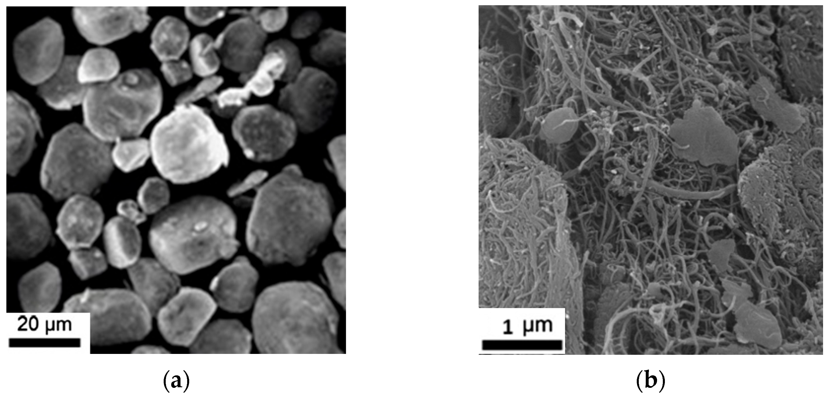
2.1. Raw Materials

In this study, aluminum powder 6061 with a 20 µm mesh size (HNYY powder Co., Ltd. Henan, China) was used in combination with multi-walled carbon nanotubes (MWCNTs) with an internal diameter of 5–10 nm and 10–30 µm in length (DYNANO Co., Ltd. China). Table 1 summarizes the key attributes of nanotubes.
MWCNTs are used over SWCNTs for two main reasons: firstly, SWCNTs are mostly used in electrical applications because of their unique electronic properties. Secondly, SWCNTs are more challenging to produce in high purity; consequently, they are often way more expensive than MWCNTs, which limits their application, especially in the mechanical and material engineering fields. Figure 1 shows the SEM images of the Al and CNT powder.

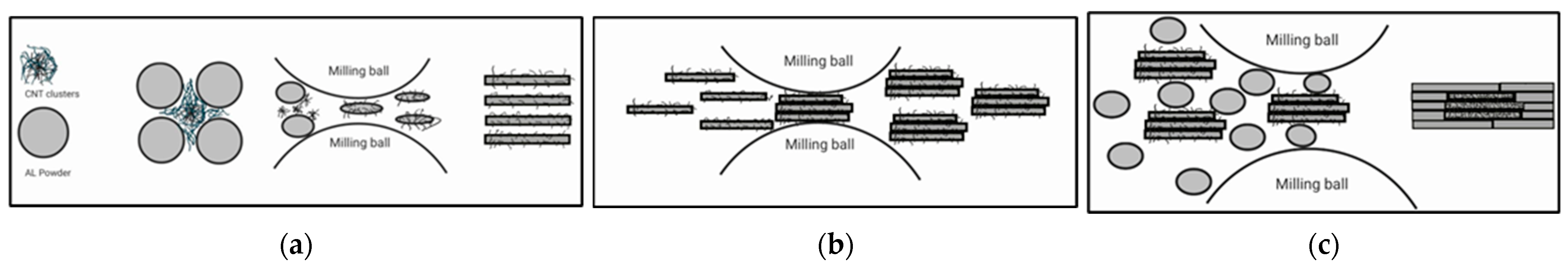
2.2. Al\CNT Powder Preparation

Figure 2 shows the dispersion procedure flowchart in the DM-SSBM method. Two main steps were needed to fabricate the AL/CNT powders: (1) The SSBM phase contains LSBM (175 rpm) and HSBM (400 rpm), and (2) the DM phase contains adding unmilled AL particles to the powder and milling for 1 h in HSBM (400 rpm). Three more samples using conventional HSBM, SSBM, and DM methods were synthesized to compare the final mechanical properties with the DM-SSBM method.
The DM-SSBM composites were mixed by a planetary ball-milling machine. The CNT powders were first dispersed in the Al matrix using the SSBM method. The powders were milled in a 250 mL stainless steel jar with the BPR = 5:1 at a speed of 135 rpm for 6 h (LSBM) and 270 rpm for 1 h (HSBM) at room temperature [45]. The milling process had 5-minute stops every 10 min to prevent excessive temperature increases. A 1 wt% solution of stearic acid was used as a processing control agent (PCA) to prevent excessive cold welding between Al particles. Figure 3 presents the equipment used for the milling process. At the second step, the dual-matrix method was applied by adding the remaining soft Al to the mixture. Then, the powders were milled for an optimum time of 60 min [15] to obtain a better dispersion ratio. Argon gas was used during the milling to prevent the powder from oxidation. The DM phase ratio studied in this paper was 25% and 50% of reinforced to unreinforced Al. After the milling step. The naming system in this study will be as follows:
DMxMRyy-SSBM
The x subscript refers to the weight percentage of the CNTs. The y subscripts refer to the overall mixing ratio of the reinforced Al matrix to the unreinforced particles.
Three other samples using HSBM, SSBM, and DM were synthesized in order to compare the final mechanical properties. The HSBM powder was milled in the same jar under the same conditions for 5 h at 400 rpm. DM and SSBM powders were synthesized under the same conditions as [14,15]. Key process parameters (milling speed, time, BPR, dual-matrix ratios) were selected based on prior reports, demonstrating their critical influence on CNT dispersion and mechanical outcomes. These parameter choices were designed to optimize the balance between sufficient UTS and ductility by preservation of CNT integrity and controlling the amount of cold welding.

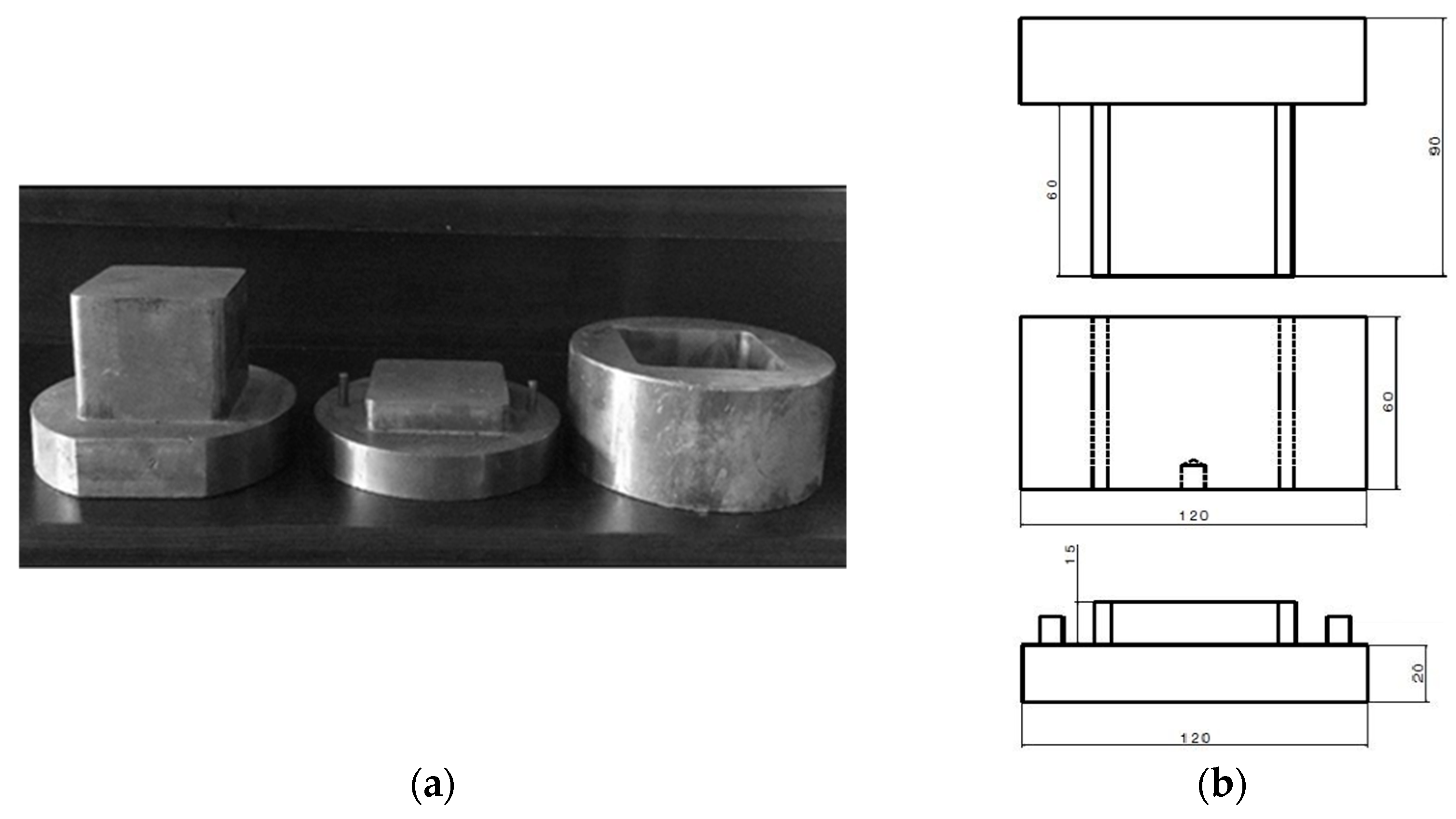
2.3. Consolidation of Al/CNT Powders

All powders were consolidated as rectangular planar parts using a stainless steel die according to Figure 4, with a 65 mm width and 5 mm thickness, using a 300 Mpa uniaxial press for 1 h. After pressing, the samples were sintered at a temperature of 550 °C for 5 h using a controlled atmosphere to prevent any oxidation. In order to gain better dispersion and higher density, the sintered samples were hot-rolled at 480 °C 17 times to reach 1.6 mm thickness. The reduction percentage for each rolling pass is 4% (0.2 mm). After each set of 4 passes, due to temperature loss, samples were placed in a furnace and heated up to 480 °C again to perform flawless rolling. During the process, all the samples were covered by aluminum foil to prevent contamination and excessive temperature loss. The same consolidation method was used for all the different samples. Although CNTs are initially dispersed onto individual aluminum powder particles, the subsequent high-speed ball milling, sintering, and rolling processes result in a continuous aluminum matrix in the final composite, which physically encapsulates and interacts with the CNTs.

3. Results and Discussion

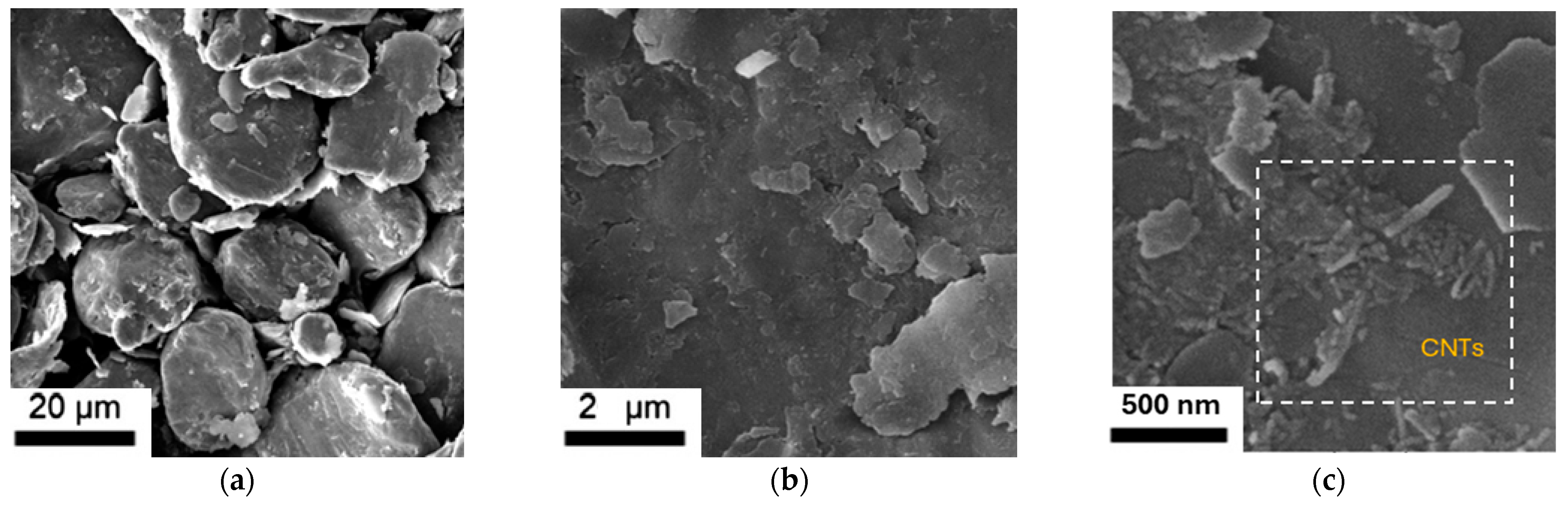
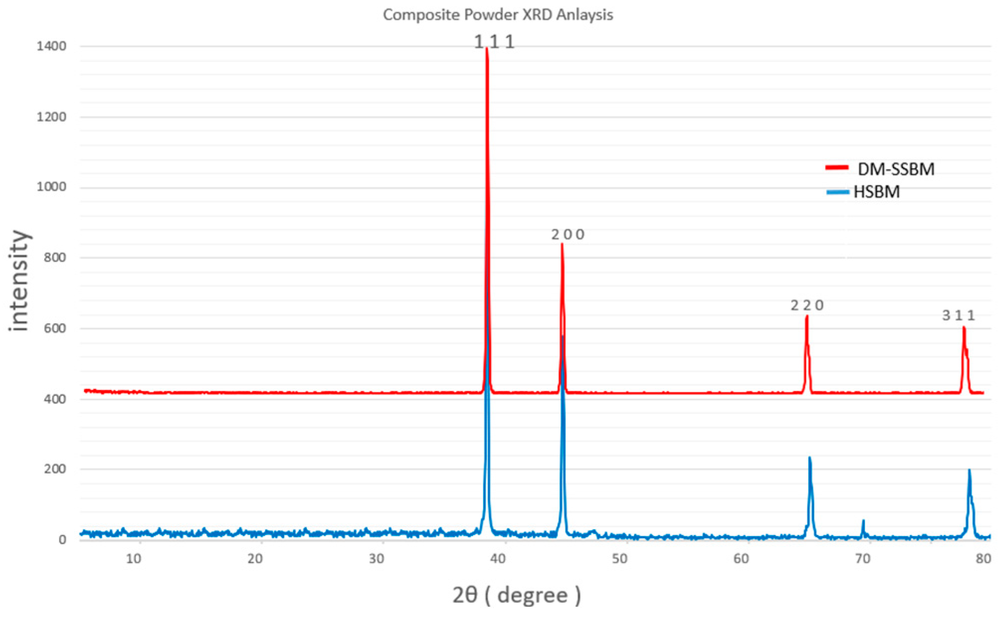
3.1. Al/CNT Powder Morphology

There are three different phases in the milling process to obtain the final DM-SSBM powder. Figure 5 illustrates the overall dispersion mechanism of the CNT powders during the PBM process. In Figure 5a, under the LSBM process, CNT clusters are dispersed on the Al flake powder surface, while the powder flattening is happening due to the collision between milling balls and the spherical Al powders. At this stage, no cold welding is happening between the Al particles, due to the low colliding energy and presence of the PCA (stearic acid). Figure 5b presents the HSBM phase, where the flattened Al particles containing CNTs on the surface are joining together and forming bigger particles due to the cold welding happening under high-energy collision between milling balls. During the last phase, pure aluminum is added to the mixed powder through an additional step of HSBM, applying a higher rotational speed to increase the cold welding. This approach ensures that the final product remains ductile while enhancing its yield strength.
Scanning electron microscopy (SEM) analyses of both powder and bulk Al/CNT composites were performed using a TESCAN MIRA3 XMU. As shown in Figure 6, the difference between powder morphology at various stages is clearly visible. As mentioned in the previous paragraph, after the LSBM stage, Al particles become flattened, forming a flake powder shape, with CNT particles well dispersed on the flattened surface, as shown in Figure 6a. In Figure 6b, after the first HSBM stage, particle size increases due to the cold welding between the flake AL powders. The average particle size is increased significantly to the range of 40–60 µm. After the first HSBM process, to obtain the DM phase, some pure AL powders were added to the mixture, and the process went through another HSBM process. Figure 6c illustrates the size and shape difference between the milled and unmilled AL powders, with bigger particles being the milled and welded Al particles.
Figure 7 analyzes the dispersion quality of the CNTs on Al particles after the LSBM phase. As shown, the dispersion quality is acceptable with some small clusters observed on certain flake surfaces, as shown in Figure 7b, and no significant clusters are present between the Al particles.
Figure 8 presents SEM images of the Al/CNT composite powder after the final DM-SSBM stage. As it is shown in Figure 8a, after conducting HSBM and adding pure Al to the milled powder mixture, no CNT clusters are visible. Investigating the particle surfaces revealed some CNT on the powder surface (Figure 8b,c). Their presence on the powder surface confirms that the HSBM process effectively separated the agglomerates without eliminating or damaging the CNTs. This observation aligns with XRD analysis, which verifies that the CNT structure remains intact. Overall, these findings demonstrate that the HSBM phase significantly improves CNT dispersion by eliminating agglomerates and promoting homogeneous integration into the aluminum matrix, without compromising the structural integrity of the CNTs.
X-ray diffraction analysis was performed following the θ–2θ method, using a Bruker Advance D8 X-ray diffractometer (XRD). In this configuration, the X-ray tube remains stationary while the sample and detector rotate at speeds of θ°/min and 2θ°/min, respectively. The scan range was set between 5° and 80°, with a step size of 0.04°. The first and most intense peak appears at 38°, corresponding to the {111} plane of aluminum. Subsequent peaks are observed at 46°, 66°, and 79°, which correspond to the {200}, {220}, and {311} planes, respectively. This diffraction pattern is in full agreement with the standard reference data for pure aluminum powder available in the PDF2 database. Based on this, it can be concluded that in samples produced with DM, SSBM, and DM-SSBM methods, no peaks associated with aluminum carbide (Al4C3) are present, indicating that this phase was not formed during the milling process [28].
In contrast, the HSBM sample exhibits a weak diffraction peak at 69°, which corresponds to aluminum carbide (Al4C3). Although this peak appears with relatively low intensity, it confirms the presence of Al4C3 in the matrix. These results suggest that prolonged high-energy ball milling (HSBM) leads to the inevitable formation of the aluminum carbide phase, which could negatively affect the final properties of the composite material. Figure 9 shows the XRD analysis graphs for both samples.
The microstructural and phase analysis results confirm that the DM-SSBM powder preparation method results in uniform CNT dispersion with no formation of the aluminum carbide (Al4C3) phases. The sequential low- and high-speed milling, followed by adding pure Al, balances the cold welding and prevents damaging the CNT structure, compared to the conventional HSBM approach.

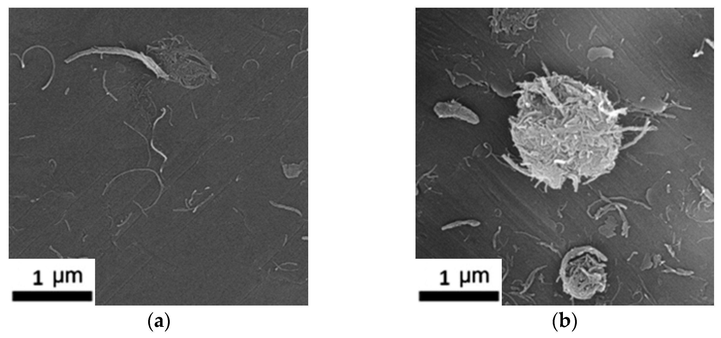
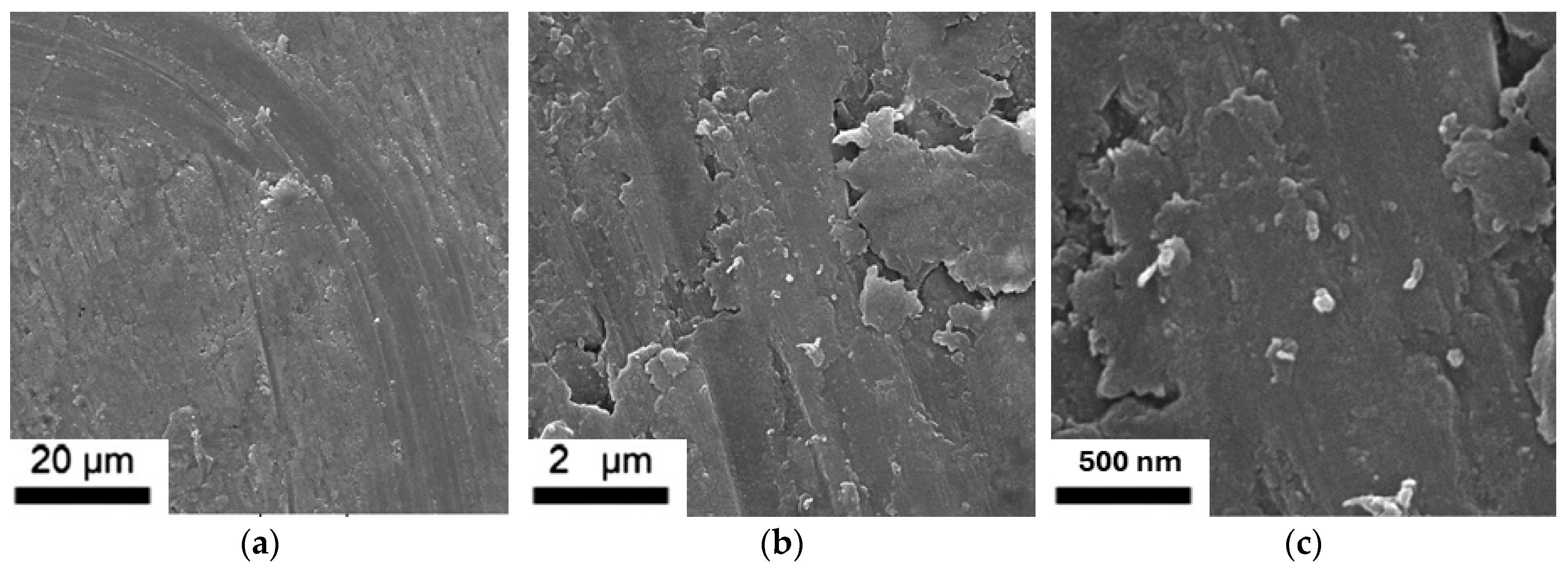
3.2. Post-Rolling Microstructural Analysis

Figure 10 shows SEM images of the DM1MR50-SSBM composite after hot rolling. The surface displays long, plate-like features that run parallel to the rolling direction, confirming that the material was strongly compressed and its grains were stretched out during rolling. Importantly, no carbon-nanotube (CNT) fragments can be seen on the surface; only the aluminum matrix is visible. Given the cold-welding, sintering, and hot-rolling stages, the final bulk composite no longer consists of isolated particles, but rather a continuous metallic matrix embedding the nanotubes. This observation justifies referring to the aluminum phase as a matrix. Two factors likely explain why CNTs no longer appear at the surface:
  • High rolling pressure pushes any surface CNTs slightly below the top layer as the metal flows.
  • The elevated rolling temperature softens the aluminum, allowing it to wrap around and fully cover the CNTs.
Because SEM detects only the surface of the samples, CNTs buried just beneath the surface are invisible in these images. This is beneficial as it prevents them from pulling out at the surface, and positions them inside the load-bearing aluminum, helping to explain the good toughness reported in Section 3.2.

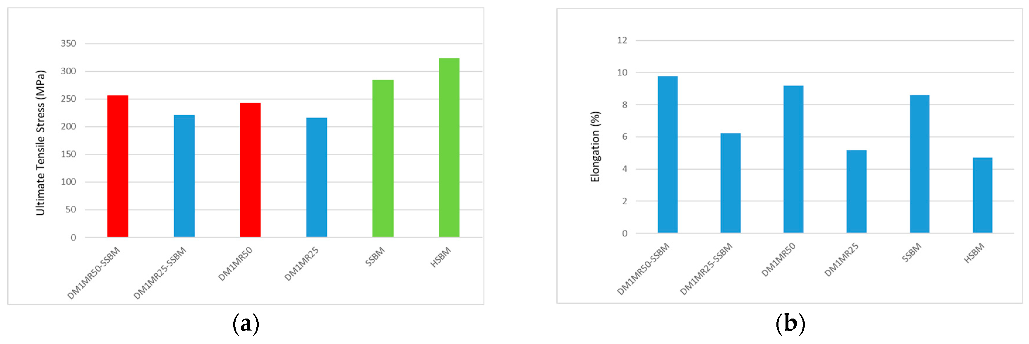
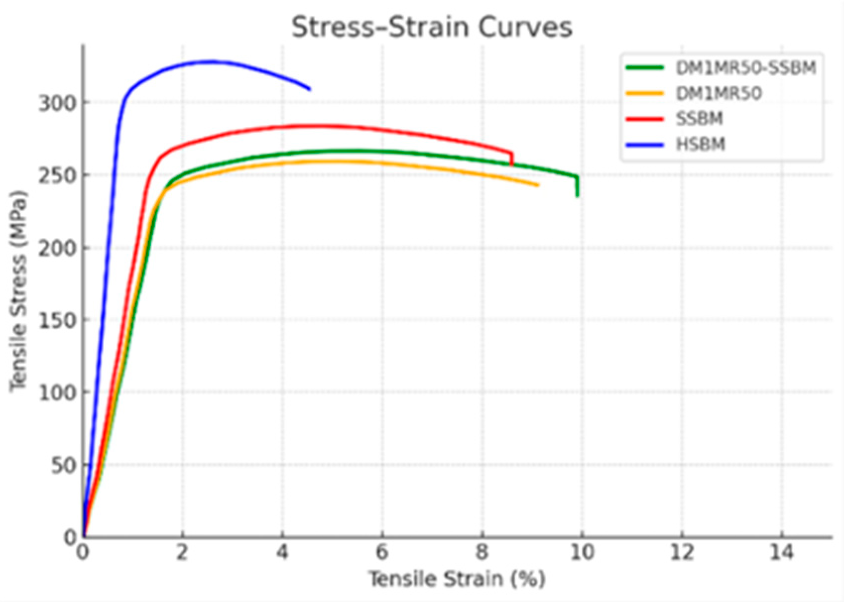
3.3. Mechanical Properties

To evaluate the mechanical properties of the Al/CNT composites, tensile tests using ASTM B557M-15 [50] standard were conducted on all samples, including those produced via HSBM, SSBM, DM, and the combined DM-SSBM. The reported tensile strength values represent the mean of three repeated measurements, conducted in accordance with ISO/IEC 17025 [51] standards. Figure 11 shows the geometry of the test samples. According to the ASTM standard, the test was conducted at room temperature (25 °C) and 40% humidity. Three specimens per composition were tested to ensure repeatability, and the average values were reported.
Results for the mechanical tests are presented in Figure 12.
As depicted in Figure 12, adding the shift-speed ball-milling (SSBM) step to the dual-matrix (DM) powders gives an acceptable raise to the final UTS in the manufactured composite, and, at the 50% mixing ratio (DM1MR50), the SSBM-combined sample reaches roughly 267 MPa—around 3% higher than the DM-only sample—as shown in the ultimate tensile strength bar chart. The same pattern appears at 25%: DM1MR25-SSBM is stronger than DM1MR25. This trend is due to the high-energy milling stage in SSBM, which increases cold-welding between flakes and disperses the carbon nanotubes more uniformly, improving load transfer without introducing additional carbide form into the matrix. Meanwhile, the unmilled AL that was added in the dual-matrix stage limits overwork and keeps residual stresses low. As a result, the DM-SSBM samples sit between the aggressive HSBM and the softer DM powders in terms of ultimate stress. This trend is clearly visible in both the stress–strain curve and the UTS bar chart, where the HSBM sample achieves 328 MPa and the DM-only routes are closer to 245–260 MPa. The steep rise and sudden drop of the HSBM curve (blue) in the stress–strain plot also emphasize its brittle nature and strong cold-welding response.
The DM-SSBM compositions also deliver more ductility than either the single-stage SSBM or the high-energy HSBM samples. DM1MR50-SSBM has about 13% tensile strain, whereas SSBM levels off near 11% and HSBM fails below 5. These trends are clearly visible by the stress–strain curves depicted in Figure 13: the DM1MR50-SSBM extends furthest along the x-axis, while the blue HSBM curve fails quickly after peak stress. The softer, unmilled Al that defines the dual-matrix design provides local zones that can yield and blunt micro-cracks once the CNT-reinforced areas have carried the peak load. Meanwhile, the low-speed phase of SSBM limits CNT breakage and controls the Al4C3 formation, so the composite preserves its ability to stretch.
Additionally, the tensile test results illustrated in Figure 13 reveal a considerable difference in energy absorption capability of the samples. The area under the stress-strain curve, which represents the mechanical energy absorbed per unit volume before failure, is a critical indicator of the material’s toughness. The DM1MR50-SSBM sample manufactured by the new proposed method in this study absorbed approximately 23.4 MJ/m3, which is more than SSBM and DM1MR50 with 21.8 MJ/m3 and 21.2 MJ/m3, respectively. The higher toughness in the DM-SSBM sample comes from its combination of higher ultimate tensile strength and greater elongation, which together produce a larger area under the stress-strain curve. As a result, DM1MR50-SSBM offers the most favorable mechanical profile among the tested samples, making it an excellent candidate for applications requiring materials that can absorb impact energy efficiently, such as lightweight crash components, protective barriers, or high-performance structural parts. Table 2 summarizes the information about energy absorption between the three samples.
Overall, the combined mechanical analysis clearly demonstrates that the DM1MR50-SSBM sample delivers the most advantageous balance of strength, ductility, and energy absorption among the tested composites. These improvements are directly linked to its optimized processing route, which combines dual-matrix design with shift-speed ball milling. While additional microstructural characterization (e.g., fracture surface analysis) could provide deeper insights, the current findings already highlight the strong potential of the DM-SSBM route for applications demanding high toughness and reliable energy dissipation.

4. Conclusions

In this study, a novel flake powder metallurgy approach combining dual-matrix (DM) design with shift-speed ball milling (SSBM) was successfully applied to fabricate Al/CNT composites with enhanced mechanical properties. Compared to conventional HSBM, SSBM, and DM methods, the DM-SSBM method delivered the most balanced performance, achieving both high ultimate tensile strength (~267 MPa) and superior ductility (~9.9%). Tensile testing revealed that DM-SSBM samples absorbed approximately 23.4 MJ/m3 of mechanical energy before failure—outperforming both the DM1MR50 (21.2 MJ/m3) and SSBM (21.8 MJ/m3). This improvement comes from the optimized combination of CNT dispersion, cold welding, and controlled matrix softening, which together enhance both load-bearing capacity and plastic deformation ability.
Furthermore, phase analysis confirmed that the DM-SSBM method effectively prevented Al4C3 formation, preserving the integrity of the CNT reinforcement. Although simulation and modeling approaches offer powerful tools for many composite systems, accurately modeling nanoscale interactions between CNTs and the aluminum matrix remains nearly impossible with current computational resources. Therefore, this study relies on experimentally validated methods, supported by literature, to achieve systematic material optimization.
These findings highlight the potential of DM-SSBM composites for applications requiring lightweight, high-toughness materials—particularly in energy-absorbing components such as crash structures, protective shells, and advanced structural parts. Future work should explore the microstructural evolution under cyclic loading and evaluate long-term durability to fully map the industrial potential of these advanced composites.

Author Contributions

Conceptualization, H.R.; methodology, H.R.; investigation, H.R.; resources, H.R.; writing—original draft preparation, H.R., writing—review and editing, A.V.; supervision, A.V. All authors have read and agreed to the published version of the manuscript.

Funding

This research received no external funding.

Data Availability Statement

The raw data supporting the conclusions of this article will be made available by the authors on request.

Conflicts of Interest

The authors declare no conflicts of interest.

Abbreviations

The following abbreviations are used in this manuscript:
CNTCarbon Nanotubes
MWCNTMulti-wall Carbon Nanotubes
SWCNTSingle-wall Carbon Nanotubes
BPRBall-to-Powder Ratio
LSBMLow-speed Ball Milling
HSBMHigh-speed Ball Milling
SSBMShift-speed Ball Milling
DMDual Matrix
DM-SSBMDual-matrix Shift-speed Ball Milling
MRMixing Ratio

References

  1. Khanna, V.; Kumar, V.; Bansal, S.A. Mechanical properties of aluminium-graphene/carbon nanotubes (CNTs) metal matrix composites: Advancement, opportunities and perspective. Mater. Res. Bull. 2021, 138, 111224. [Google Scholar] [CrossRef]
  2. Ogawa, F.; Masuda, C. Fabrication and the mechanical and physical properties of nanocarbon-reinforced light metal matrix composites: A review and future directions. Mater. Sci. Eng. A 2021, 820, 141542. [Google Scholar] [CrossRef]
  3. Cha, S.I.; Kim, K.T.; Arshad, S.N.; Mo, C.B.; Hong, S.H. Extraordinary strengthening effect of carbon nanotubes in metal-matrix nanocomposites processed by molecular-level mixing. Adv. Mater. 2005, 17, 1377–1381. [Google Scholar] [CrossRef] [PubMed]
  4. Dong, S.; Tu, J.; Zhang, X. An investigation of the sliding wear behavior of Cu-matrix composite reinforced by carbon nanotubes. Mater. Sci. Eng. A 2001, 313, 83–87. [Google Scholar] [CrossRef]
  5. Agarwal, A.; Bakshi, S.R.; Lahiri, D. Carbon Nanotubes: Reinforced Metal Matrix Composites; CRC press: Boca Raton, FL, USA, 2018. [Google Scholar]
  6. George, R.; Kashyap, K.; Rahul, R.; Yamdagni, S. Strengthening in carbon nanotube/aluminium (CNT/Al) composites. Scr. Mater. 2005, 53, 1159–1163. [Google Scholar] [CrossRef]
  7. Curtin, W.A.; Sheldon, B.W. CNT-reinforced ceramics and metals. Mater. Today 2004, 7, 44–49. [Google Scholar] [CrossRef]
  8. Seidel, G.D.; Lagoudas, D.C. Micromechanical analysis of the effective elastic properties of carbon nanotube reinforced composites. Mech. Mater. 2006, 38, 884–907. [Google Scholar] [CrossRef]
  9. Coleman, J.N.; Khan, U.; Blau, W.J.; Gun’ko, Y.K. Small but strong: A review of the mechanical properties of carbon nanotube–polymer composites. Carbon 2006, 44, 1624–1652. [Google Scholar] [CrossRef]
  10. Ajayan, P.M.; Schadler, L.S.; Giannaris, C.; Rubio, A. Single-walled carbon nanotube–polymer composites: Strength; weakness. Adv. Mater. 2000, 12, 750–753. [Google Scholar] [CrossRef]
  11. Bakshi, S.R.; Lahiri, D.; Agarwal, A. Carbon nanotube reinforced metal matrix composites-a review. Int. Mater. Rev. 2010, 55, 41–64. [Google Scholar] [CrossRef]
  12. Saheb, N.; Iqbal, Z.; Khalil, A.; Hakeem, A.S.; Al Aqeeli, N.; Laoui, T.; Al-Qutub, A.; Kirchner, R.; Francis, L.D. Spark plasma sintering of metals and metal matrix nanocomposites: A review. J. Nanomater. 2012, 2012, 18. [Google Scholar] [CrossRef]
  13. Neubauer, E.; Kitzmantel, M.; Hulman, M.; Angerer, P. Potential and challenges of metal-matrix-composites reinforced with carbon nanofibers and carbon nanotubes. Compos. Sci. Technol. 2010, 70, 2228–2236. [Google Scholar] [CrossRef]
  14. Xu, R.; Tan, Z.; Xiong, D.; Fan, G.; Guo, Q.; Zhang, J.; Su, Y.; Li, Z.; Zhang, D. Balanced strength and ductility in CNT/Al composites achieved by flake powder metallurgy via shift-speed ball milling. Compos. Part A Appl. Sci. Manuf. 2017, 96, 57–66. [Google Scholar] [CrossRef]
  15. Salama, E.I.; Abbas, A.; Esawi, A.M. Preparation and properties of dual-matrix carbon nanotube-reinforced aluminum composites. Compos. Part A Appl. Sci. Manuf. 2017, 99, 84–93. [Google Scholar] [CrossRef]
  16. Rikhtegar, F.; Shabestari, S.; Saghafian, H. Microstructural evaluation and mechanical properties of Al-CNT nanocomposites produced by different processing methods. J. Alloys Compd. 2017, 723, 633–641. [Google Scholar] [CrossRef]
  17. Liu, Z.; Xiao, B.; Wang, W.; Ma, Z. Modelling of carbon nanotube dispersion and strengthening mechanisms in Al matrix composites prepared by high energy ball milling-powder metallurgy method. Compos. Part A Appl. Sci. Manuf. 2017, 94, 189–198. [Google Scholar] [CrossRef]
  18. Liu, X.; Li, C.; Eckert, J.; Prashanth, K.G.; Renk, O.; Teng, L.; Liu, Y.; Bao, R.; Tao, J.; Shen, T.; et al. Microstructure evolution and mechanical properties of carbon nanotubes reinforced Al matrix composites. Mater. Charact. 2017, 133, 122–132. [Google Scholar] [CrossRef]
  19. Huang, H.; Fan, G.; Tan, Z.; Xiong, D.-B.; Guo, Q.; Guo, C.; Li, Z.; Zhang, D. Superplastic behavior of carbon nanotube reinforced aluminum composites fabricated by flake powder metallurgy. Mater. Sci. Eng. A 2017, 699, 55–61. [Google Scholar] [CrossRef]
  20. Chen, B.; Shen, J.; Ye, X.; Jia, L.; Li, S.; Umeda, J.; Takahashi, M.; Kondoh, K. Length effect of carbon nanotubes on the strengthening mechanisms in metal matrix composites. Acta Mater. 2017, 140, 317–325. [Google Scholar] [CrossRef]
  21. Zare, H.; Jahedi, M.; Toroghinejad, M.R.; Meratian, M.; Knezevic, M. ; Compressive; shear, and fracture behavior of CNT reinforced Al matrix composites manufactured by severe plastic deformation. Mater. Des. 2016, 106, 112–119. [Google Scholar] [CrossRef]
  22. Mokdad, F.; Chen, D.; Liu, Z.; Xiao, B.; Ni, D.; Ma, Z. Deformation and strengthening mechanisms of a carbon nanotube reinforced aluminum composite. Carbon 2016, 104, 64–77. [Google Scholar] [CrossRef]
  23. Liu, Z.; Zhao, K.; Xiao, B.; Wang, W.; Ma, Z. Fabrication of CNT/Al composites with low damage to CNTs by a novel solution-assisted wet mixing combined with powder metallurgy processing. Mater. Des. 2016, 97, 424–430. [Google Scholar] [CrossRef]
  24. Chen, B.; Kondoh, K.; Imai, H.; Umeda, J.; Takahashi, M. Simultaneously enhancing strength and ductility of carbon nanotube/aluminum composites by improving bonding conditions. Scr. Mater. 2016, 113, 158–162. [Google Scholar] [CrossRef]
  25. Chen, B.; Kondoh, K.; Imai, H.; Umeda, J. Effect of initial state on dispersion evolution of carbon nanotubes in aluminium matrix composites during a high-energy ball milling process. Powder Metall. 2016, 59, 216–222. [Google Scholar] [CrossRef]
  26. Carvalho, O.; Miranda, G.; Soares, D.; Silva, F. Carbon nanotube dispersion in aluminum matrix composites—Quantification and influence on strength. Mech. Adv. Mater. Struct. 2016, 23, 66–73. [Google Scholar] [CrossRef]
  27. Simões, S.; Viana, F.; Reis, M.A.; Vieira, M.F. Influence of dispersion/mixture time on mechanical properties of Al–CNTs nanocomposites. Compos. Struct. 2015, 126, 114–122. [Google Scholar] [CrossRef]
  28. Liao, J.; Tan, M.-J. Mixing of carbon nanotubes (CNTs) and aluminum powder for powder metallurgy use. Powder Technol. 2011, 208, 42–48. [Google Scholar] [CrossRef]
  29. Jiang, L.; Li, Z.; Fan, G.; Cao, L.; Zhang, D. The use of flake powder metallurgy to produce carbon nanotube (CNT)/aluminum composites with a homogenous CNT distribution. Carbon 2012, 50, 1993–1998. [Google Scholar] [CrossRef]
  30. Liu, Z.; Xu, S.; Xiao, B.; Xue, P.; Wang, W.; Ma, Z. Effect of ball-milling time on mechanical properties of carbon nanotubes reinforced aluminum matrix composites. Compos. Part A Appl. Sci. Manuf. 2012, 43, 2161–2168. [Google Scholar] [CrossRef]
  31. Kwon, H.; Leparoux, M. Hot extruded carbon nanotube reinforced aluminum matrix composite materials. Nanotechnology 2012, 23, 415701. [Google Scholar] [CrossRef]
  32. Kim, K.T.; Cha, S.I.; Hong, S.H. Hardness and wear resistance of carbon nanotube reinforced Cu matrix nanocomposites. Mater. Sci. Eng. A 2007, 449, 46–50. [Google Scholar] [CrossRef]
  33. Lin, C.; Chang, Z.-C.; Tung, Y.; Ko, Y.-Y. Manufacturing and tribological properties of copper matrix/carbon nanotubes composites. Wear 2011, 270, 382–394. [Google Scholar] [CrossRef]
  34. Shukla, A.; Nayan, N.; Murty, S.; Mondal, K.; Sharma, S.; George, K.M.; Bakshi, S.R. Processing copper–carbon nanotube composite powders by high energy milling. Mater. Charact. 2013, 84, 58–66. [Google Scholar] [CrossRef]
  35. Chen, X.; Li, W.; Chen, C.; Xu, L.; Yang, Z.; Hu, J. Preparation and properties of Cu matrix composite reinforced by carbon nanotubes. Trans. Nonferr. Met. Soc. China 2005, 15, 314–318. [Google Scholar]
  36. Arribas, A.S.; Bermejo, E.; Chicharro, M.; Zapardiel, A.; Luque, G.L.; Ferreyra, N.F.; Rivas, G.A. Analytical applications of a carbon nanotubes composite modified with copper microparticles as detector in flow systems. Anal. Chim. Acta 2006, 577, 183–189. [Google Scholar] [CrossRef]
  37. Chen, D.; Chen, L.; Liu, S.; Ma, C.; Chen, D.; Wang, L. Microstructure and hydrogen storage property of Mg/MWNTs composites. J. Alloys Compd. 2004, 372, 231–237. [Google Scholar] [CrossRef]
  38. Carreño-Morelli, E.; Yang, J.; Couteau, E.; Hernadi, K.; Seo, J.W.; Bonjour, C.; Forró, L.; Schaller, R. Carbon nanotube/magnesium composites. Phys. Status Solidi (A) 2004, 201, R53–R55. [Google Scholar] [CrossRef]
  39. Kondoh, K.; Fukuda, H.; Umeda, J.; Imai, H.; Fugetsu, B.; Endo, M. Microstructural and mechanical analysis of carbon nanotube reinforced magnesium alloy powder composites. Mater. Sci. Eng. A 2010, 527, 4103–4108. [Google Scholar] [CrossRef]
  40. Li, C.; Wang, X.; Wu, K.; Liu, W.; Xiang, S.; Ding, C.; Hu, X.; Zheng, M. Distribution and integrity of carbon nanotubes in carbon nanotube/magnesium composites. J. Alloys Compd. 2014, 612, 330–336. [Google Scholar] [CrossRef]
  41. He, C.; Zhao, N.; Shi, C.; Du, X.; Li, J.; Li, H.; Cui, Q. An approach to obtaining homogeneously dispersed carbon nanotubes in Al powders for preparing reinforced Al-matrix composites. Adv. Mater. 2007, 19, 1128–1132. [Google Scholar] [CrossRef]
  42. Zhou, W.; Bang, S.; Kurita, H.; Miyazaki, T.; Fan, Y.; Kawasaki, A. Interface and interfacial reactions in multi-walled carbon nanotube-reinforced aluminum matrix composites. Carbon 2016, 96, 919–928. [Google Scholar] [CrossRef]
  43. Rikhtegar, F.; Shabestari, S.; Saghafian, H. The homogenizing of carbon nanotube dispersion in aluminium matrix nanocomposite using flake powder metallurgy and ball milling methods. Powder Technol. 2015, 280, 26–34. [Google Scholar] [CrossRef]
  44. Li, Q.; Rottmair, C.A.; Singer, R.F. CNT reinforced light metal composites produced by melt stirring and by high pressure die casting. Compos. Sci. Technol. 2010, 70, 2242–2247. [Google Scholar] [CrossRef]
  45. Chen, M.; Fan, G.; Tan, Z.; Xiong, D.; Guo, Q.; Su, Y.; Zhang, J.; Li, Z.; Naito, M.; Zhang, D. Design of an efficient flake powder metallurgy route to fabricate CNT/6061Al composites. Mater. Des. 2018, 142, 288–296. [Google Scholar] [CrossRef]
  46. Choi, H.; Shin, J.; Bae, D. The effect of milling conditions on microstructures and mechanical properties of Al/MWCNT composites. Compos. Part A Appl. Sci. Manuf. 2012, 43, 1061–1072. [Google Scholar] [CrossRef]
  47. Morsi, K.; Esawi, A. Effect of mechanical alloying time and carbon nanotube (CNT) content on the evolution of aluminum (Al)–CNT composite powders. J. Mater. Sci. 2007, 42, 4954–4959. [Google Scholar] [CrossRef]
  48. Bakshi, S.R.; Agarwal, A. An analysis of the factors affecting strengthening in carbon nanotube reinforced aluminum composites. Carbon 2011, 49, 533–544. [Google Scholar] [CrossRef]
  49. Esawi, A.M.; El Borady, M.A. Carbon nanotube-reinforced aluminium strips. Compos. Sci. Technol. 2008, 68, 486–492. [Google Scholar] [CrossRef]
  50. ASTM B557M-15; Standard Test Methods for Tension Testing Wrought and Cast Aluminum- and Magnesium-Alloy Products (Metric). ASTM: West Conshohocken, PA, USA, 2023. Available online: https://store.astm.org/b0557m-15.html (accessed on 1 June 2025).
  51. ISO/IEC 17025; Testing and Calibration Laboratories. ISO: Geneva, Switzerland, 2017. Available online: https://www.iso.org/publication/PUB100424.html (accessed on 1 June 2025).
Figure 1. SEM images of (a) aluminum powder, (b) CNTs.
Designs 09 00082 g001
Figure 2. The AL/CNT composite powders milling steps flowchart.
Designs 09 00082 g002
Figure 3. (a) The stainless steel milling jar filled with the milling balls, (b) controlled Argon insertion procedure, (c) the planetary ball-milling machine.
Designs 09 00082 g003
Figure 4. (a) The stainless steel press die, (b) schematic of the die.
Designs 09 00082 g004
Figure 5. Dispersion and deformation/welding mechanism in (a) LSBM, (b) HSBM, and (c) DM-SSBM of Al/CNT powders.
Designs 09 00082 g005
Figure 6. FE-SEM: (a) CNT dispersion on the Al particles after the LSBM, (b) increased flake powder dimension after HSBM, (c) comparing the pure Al particles (smaller round particles) with the milled ones (bigger flattened particles) in the DM phase.
Designs 09 00082 g006
Figure 7. (a) CNT dispersion on the Al powder surface, (b) small CNT cluster found on Al powder surface.
Designs 09 00082 g007
Figure 8. SEM images of final DM-SSBM sample: (a) 20 µm, (b) 2 µm, and (c) 500 nm.
Designs 09 00082 g008
Figure 9. XRD analysis of powder samples prepared by DM-SSBMHSBM methods.
Designs 09 00082 g009
Figure 10. SEM micrographs of the DM1MR50-SSBM composite after hot rolling, showing rolling-induced deformation texture in (a) 20 µm, (b) 2 µm, and (c) 500 nm.
Designs 09 00082 g010
Figure 11. ASTM B557M-15 sample dimensions.
Designs 09 00082 g011
Figure 12. (a) Ultimate tensile strength (UTS) comparison among different samples, showing the highest UTS in SSBM and HSBM (Red for MR50, Blue for MR25 and Green for other 2 methods). (b) Elongation (%) comparison among the same sample groups.
Designs 09 00082 g012
Figure 13. Stress–strain curves for DM1MR50-SSBM, DM1MR50, SSBM, and HSBM samples.
Designs 09 00082 g013
Table 1. MWCNT main attributes.
Single-Walled Carbon Nanotubes
Outside Diameter20–30 nm
Inside Diameter5–10 nm
Purity>95 wt%
Length10–30 micron
Electrical Conductivity>100 s/cm
Tap Density0.28 g/cm3
True Density~2.1 g/cm3
Young’s Modulus (GPa)1200
Tensile Strength (Gpa)150
Table 2. Mechanical properties of DM1MR50, DM1MR50-SSBM, and SSBM samples.
PropertyDM1MR50DM1MR50-SSBMSSBM
Ultimate Tensile Strength (MPa)259.5266.7284
Elongation (%)9.29.98.6
Energy Absorption (MJ/m3)21.223.421.8
Relative Energy Gain (%)Baseline+10%+3%
Disclaimer/Publisher’s Note: The statements, opinions and data contained in all publications are solely those of the individual author(s) and contributor(s) and not of MDPI and/or the editor(s). MDPI and/or the editor(s) disclaim responsibility for any injury to people or property resulting from any ideas, methods, instructions or products referred to in the content.

