Article

Design of Alternatives to Stained Glass with Open-Source Distributed Additive Manufacturing for Energy Efficiency and Economic Savings

1
Department of Electrical & Computer Engineering, Western University, 1151 Richmond St. N., London, ON N6A 3K7, Canada
2
Ivey Business School, Western University, 1151 Richmond St. N., London, ON N6A 3K7, Canada
*
Author to whom correspondence should be addressed.
Designs 2025, 9(4), 80; https://doi.org/10.3390/designs9040080
Submission received: 29 May 2025 / Revised: 17 June 2025 / Accepted: 19 June 2025 / Published: 24 June 2025

Abstract

Stained glass has played important roles in heritage building construction, however, conventional fabrication techniques have become economically prohibitive due to both capital costs and energy inefficiency, as well as high-level artistic and craft skills. To overcome these challenges, this study provides a new design methodology for customized 3D-printed polycarbonate (PC)-based stained-glass window alternatives using a fully open-source toolchain and methodology based on digital fabrication and hybrid crafts. Based on design thinking and open design principles, this procedure involves fabricating an additional insert made of (i) a PC substrate and (ii) custom geometries directly 3D printed on the substrate with PC-based 3D printing feedstock (iii) to be painted after the 3D printing process. This alternative is intended for customizable stained-glass design patterns to be used instead of traditional stained glass or in addition to conventional windows, making stained glass accessible and customizable according to users’ needs. Three approaches are developed and demonstrated to generate customized painted stained-glass geometries according to the different users’ skills and needs using (i) online-retrieved 3D and 2D patterns; (ii) custom patterns, i.e., hand-drawn and digital-drawn images; and (iii) AI-generated patterns. The proposed methodology shows potential for distributed applications in the building and heritage sectors, demonstrating its practical feasibility. Its use makes stained-glass-based products accessible to a broader range of end-users, especially for repairing and replicating existing conventional stained glass and designing new customizable products. The developed custom patterns are 50 times less expensive than traditional stained glass and can potentially improve thermal insulation, paving the way to energy efficiency and economic savings.

Graphical Abstract

1. Introduction

Born as an artistic decorative technique, stained glass played important historical roles in building construction [1], particularly for heritage buildings. This technique traditionally involves colored glass compositions assembled into complex patterns or pictorial drawings using metal-based striped frames, known as cames, overcoming the initial technical and economic limits in producing large glass laminates in the Middle Ages [2]. Although stained-glass windows still rely on high-level crafts and artistic skills, current fabrication processes have changed according to the technological advancements in material production and manufacturing, generating different techniques and variations, e.g., Tiffany glass or painted stained glass [3,4]. These advancements have recently paved the way for digital fabrication tools, e.g., CNC-cutting [5], connecting artistic skills and crafts with industrial design and engineering. Widely adopted for Western European cathedrals in the 12th century [6], stained-glass windows have been used in different sectors, ranging from decorative window elements to product artifacts [7]. Its applications are currently connected to (i) religious buildings, e.g., churches, synagogues, mosques, and temples; (ii) cultural and public buildings, e.g., transportation stations, libraries, or theaters; (iii) residential buildings, e.g., private houses and rooms; and (iv) interior and product design elements, e.g., mirrors and lamps. From the literature, most works on this technique have focused on the study of historical stained glass, e.g., physical and chemical analyses [8,9], their alteration due to aging, atmospheric environment, and micro-organism action [10,11], or their restoration and conservation techniques [12,13]. In contrast, very few studies have considered the environmental and economic aspects of stained glass in current building applications, as well as potential alternatives through new fabrication methods [14] or design-thinking-oriented and user-centered methodologies for wider accessibility.
Although more than half of heat loss through the outer surface of buildings can be attributed to glazed areas, substantial progress has resulted in window technology to help reduce this energy loss [15]. These technical advancements that can improve building efficiency have focused on conventional windows [16], excluding specialty windows, such as stained glass. For example, many churches, especially in Europe, were originally constructed without heating systems. Heating such large and normally uninsulated buildings is currently economically prohibitive [17]. Stained glass alone is energy inefficient in heating environments. It tends to be single glazing and has metal cames running through the entire width, which are good thermal conductors [18]. In heritage buildings, one approach to improving energy efficiency is to replace windows [19], e.g., replacing single-glazed windows with double-glazed windows [16]. A similar method for retrofitting stained glass in heating environments includes adding single- or double-glazed protective glazing, which is generally inserted on the exterior to protect the stained glass and reduce heat loss [17]. These approaches are effective but rely on existing stained-glass structures. Adding stained glass windows to new buildings or fixing existing ones is expensive. The national average cost for new stained glass in the U.S. is USD 6372/m2 (USD 592/ft2) and ranges from USD 3380 to USD 9558/m2 (USD 314 to USD 888/ft2) [20,21]. Similarly, repairing stained glass costs between USD 969 and 10,226 per m2 (USD 90 to USD 950/ft2), with the average cost being USD 4747 per m2 (USD 441/ft2) [22]. These costs add up quickly, as religious and public buildings, in particular, can have expansive window areas. For example, a single church in Chartres has more than 2000 m2 (about 21,500 ft2) of stained glass [23]. Thus, replacing all the stained glass would cost USD 12.7 million at the average rate. According to the literature, stained glass can improve energy efficiency in hot environments. Its use can effectively reduce solar transmittance and, thus, solar heat gain to reduce cooling loads of buildings in summer [24] and cooling-load-dominated environments [25]. Unfortunately, the cost of stained glass is generally prohibitive in cooling-load-dominated developing regions near the equator as well. This fact limits its real adoption in specific geographical and socio-economic contexts, lacking suitable alternatives.
The current production methods represent another key challenge in its accessibility. Despite connections with digital fabrication tools [5], stained-glass fabrication often requires high-level crafts, manual, or artistic skills to make custom patterns, excluding users without specialized training or skills. This situation further limits the broader adoption of new applications, as well as customization according to users’ needs. To this end, hybrid crafting [26,27] can further highlight the potential of integrating digital fabrication tools into traditional craft practices, making them accessible to a broader audience. Similarly, stained-glass fabrication could benefit from these hybrid approaches by including user-centered and design-thinking approaches in their design and fabrication. Open-source and open-design principles [28] can further spread them by opening the design and fabrication process through free accessible methods and tools.
Therefore, a design methodology to enable the functional and formal customization of stained glass is needed, as approaches connecting technical requirements, digital fabrication tools, and users’ needs are currently lacking. This step is crucial to make its design and fabrication accessible to end-users, allowing for the selection of energy-efficiency properties (e.g., optical properties to reduce heat gain) while reducing the cost and, ideally, increasing thermal insulation. To this end, different aspects should be combined to define a methodology for stained glass parts. One promising approach to reducing costs in glazing is to use polycarbonate (PC) [29] as an alternative material, which offers good impact and shattering resistance, light weight, cost-effectiveness, and thermal insulation. Typical manufactured raw materials for buildings are coextruded PC multi-sheet systems with chambers for insulation and UV-resistant coatings to protect them from aging [29].
In addition, distributed manufacturing has emerged as a key strategy to reduce costs and enables local production, moving toward customization and user-centered design approaches [30]. Among those, additive manufacturing (AM) processes have further enlarged the possibility of manufacturing small batches of customized parts at local levels [31,32,33], especially following open-source principles, Design for Additive Manufacturing (DfAM) [34], and open-design practices [28]. For example, prosumers could justify the cost of an open-source self-replicating rapid prototyper (RepRap)-class 3D printer [35,36] by 3D printing only one object a week and earning a 100% return on investment after five years [37]. Similarly, open-source AM allows users to locally customize and fabricate their products and share their projects in virtual repositories accessible to other users for replication or modification according to their needs [28], fostering design thinking [38,39]. There is some evidence that this transition to distributed AM is underway and involves end-users [40], meaning that distributed AM could also be applied to PC feedstock. Filament-based 3D printing, i.e., fused filament fabrication (FFF), with PC alone [41] and in mixtures is already common and well-characterized [42,43] and can even be performed from scrap PC granular waste directly thanks to fused granular fabrication (FGF) [44,45]. Moreover, AM technologies have already been used to replicate complex images and 2D models as 3D-printable 3D geometry, converting existing images into Standard Triangle Language (STL) files or 3D printing paths for gcode generation [46,47,48]. Nevertheless, similar approaches for energy-efficiency applications in the building and heritage sectors are still unexplored despite the potential economic and environmental benefits. Accessible customization and fabrication of similar products are still limited for users without specific crafts and artistic skills, highlighting the need for product alternatives and user-centered methodologies supported by accessible tools.
This study investigates the use of open-source material extrusion additive manufacturing to make customizable polycarbonate-based stained-glass alternatives for the building and heritage sectors. It presents a new design methodology for 3D-printed polycarbonate-based stained-glass window alternatives that integrate design thinking and open design using a fully open-source toolchain and methodology. The proposed DfAM methodology aims to (i) reduce the cost of new stained-glass design elements, (ii) solve the energy-efficiency issues with historic buildings using stained glass, and (iii) allow users to freely design and fabricate custom stained-glass parts through digital fabrication and hybrid crafts. This procedure involves fabricating an additional PC insert made of (i) a PC sheet as a substrate and (ii) a custom geometry directly 3D printed on the substrate with PC 3D printing feedstock (iii) to be painted after the 3D printing process. This alternative is intended to be used instead of traditional stained glass, in addition to conventional windows, to provide stained-glass design patterns or as part of new custom products. The methodology allows for tailoring the fabricated parts according to the user’s needs, technical requirements, and aesthetic considerations, integrating these aspects into the design process. Three approaches are developed and demonstrated in this study to generate customized painted stained-glass parts according to different users’ skills and needs using (i) online-retrieved 3D and 2D patterns; (ii) custom patterns, i.e., hand-drawn and digital-drawn images; and (iii) AI-generated images for patterns. After presenting the methodology and its practical feasibility, an optical spectrum characterization and transmission analysis were performed on the painted surfaces to quantify the potential heat gain reduction, as well as a preliminary economic analysis in low-resource settings.

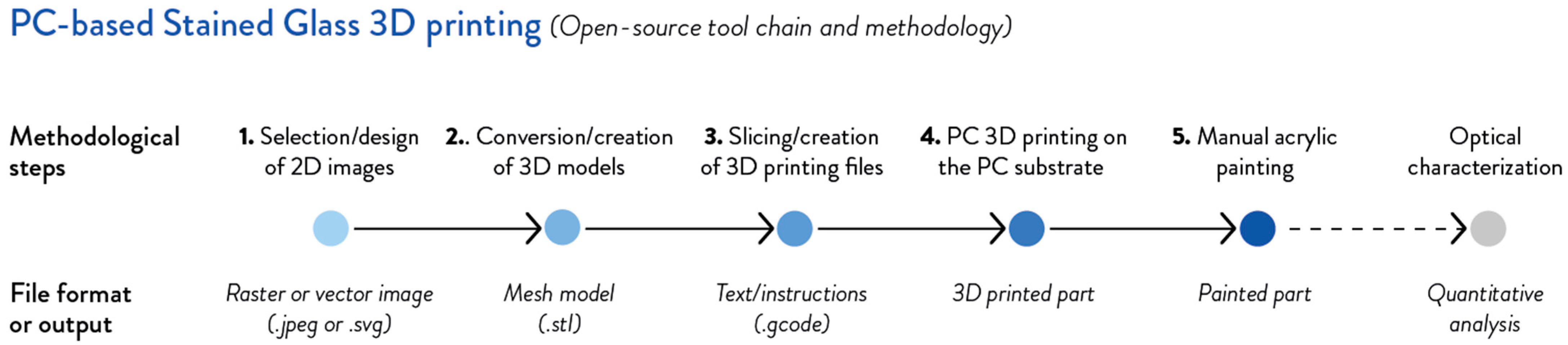
2. Materials and Methods

The design methodology presented in this work supports the design and fabrication of customizable 3D printable alternatives to stained glass parts, considering the technical requirements, user’s needs, and aesthetic language. It allows the user to tailor 3D-printable patterns and fabricate their parts, making the design and fabrication of stained glass alternatives more accessible. The methodology to fabricate 3D-printed polycarbonate-based stained-glass window alternatives, as well as the workflow of the experimental activities, followed five steps:
  • Selection or design of the 2D images for the final stained-glass patterns, e.g., sketches, drawings, raster, or vector images, according to the users’ needs and aesthetic choices (Section 2.1).
  • Conversion of the 2D images and creation of the 3D models saved in mesh format, i.e., STL, to define the pattern (Section 2.2).
  • Slicing of the 3D mesh models of the pattern and generation of the gcode files for its fabrication (Section 2.2).
  • Fabrication of the PC-based 3D design on the PC substrate via FFF 3D printing and post-processing of the 3D-printed pattern (Section 2.3).
  • Manual coloring of the 3D-printed PC inserts through acrylic painting techniques (Section 2.3).
These steps were all completed with an open-source toolchain made up of free and open-source software [49] and open hardware [50], following the principles of open design [28], design thinking [38,39], and DfAM [34] for the whole process. These five steps shown in Figure 1 are intended to be followed by the user to design and fabricate open-source customized stained-glass alternatives with 3D printing.
As a last step, the parts underwent a quantitative assessment to evaluate the optical performances and affordability of the developed alternatives. In detail, optical spectra and transmission characterizations were carried out after the fabrication and painting steps (Section 2.4), and a preliminary capital cost economic analysis was performed (Section 2.5). The 2D images, 3D mesh models, 3D printing profiles, and gcode files of the different sample patterns are available in the OSF repository [51].

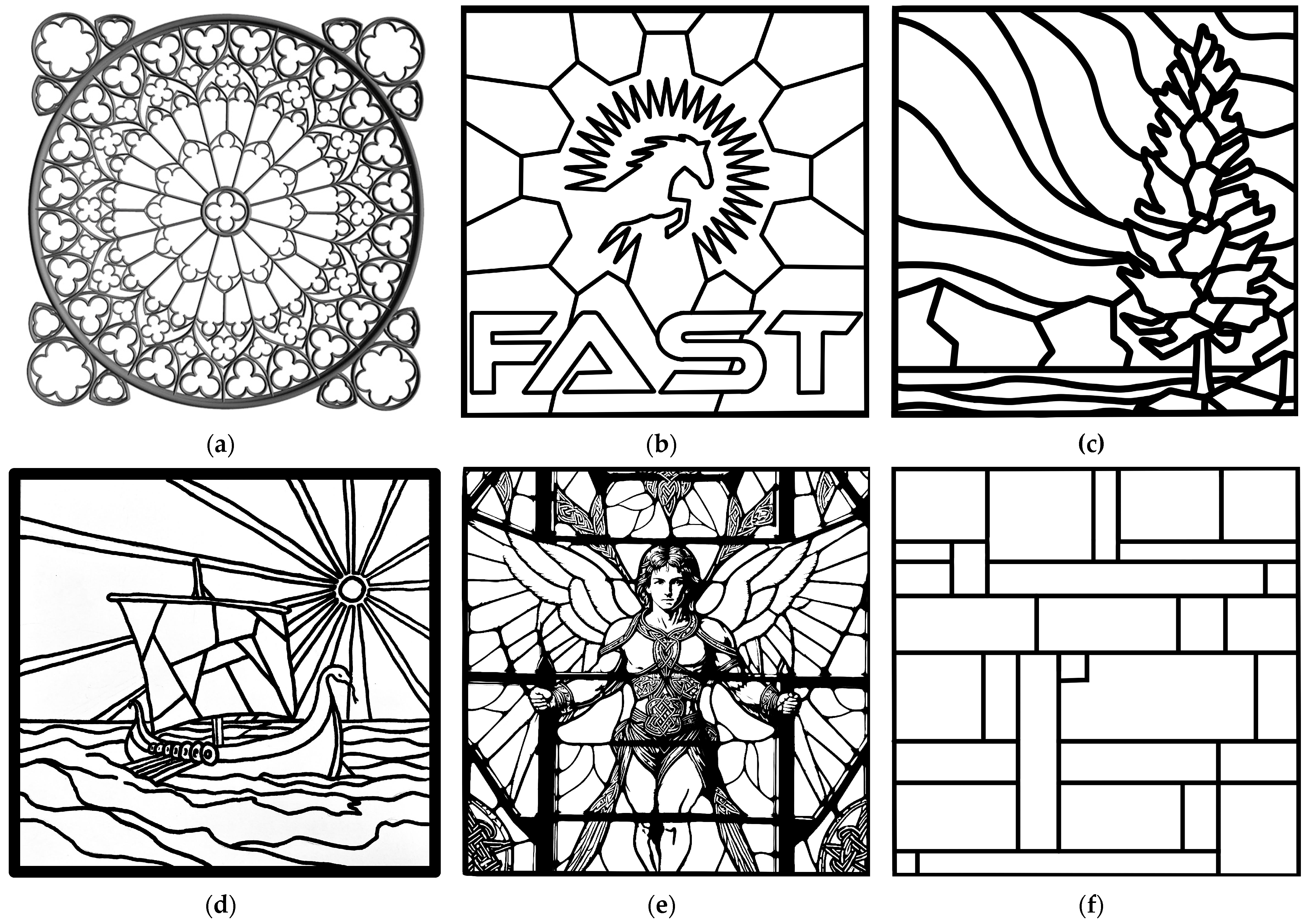
2.1. Phase 1: 2D Image Selection and Design

Three approaches were selected to generate customized paint stained-glass patterns for 3D printing, starting from 2D raster or vector images, such as Joint Photographic Experts Group (JPG) or scalable vector graphics (SVG) files. Six different designs and samples were created simulating different use contexts of the methodology (Figure 2), which means:
  • Online-retrieved 3D and 2D patterns: collected designs made up of 3D mesh models, i.e., sample stained-glass window from GrabCad [52] (Figure 2a), and 2D vector images, i.e., logo in SVG format from Appropedia [53] (Figure 2b), both available on the Internet.
  • Custom patterns, i.e., digital-drawn and hand-drawn images: novel custom designs from a digitally hand-drawn image (Northern lights, Figure 2c) and digital acquisition of a pencil sketch made on paper support (Viking ship, Figure 2d), saved as vector images.
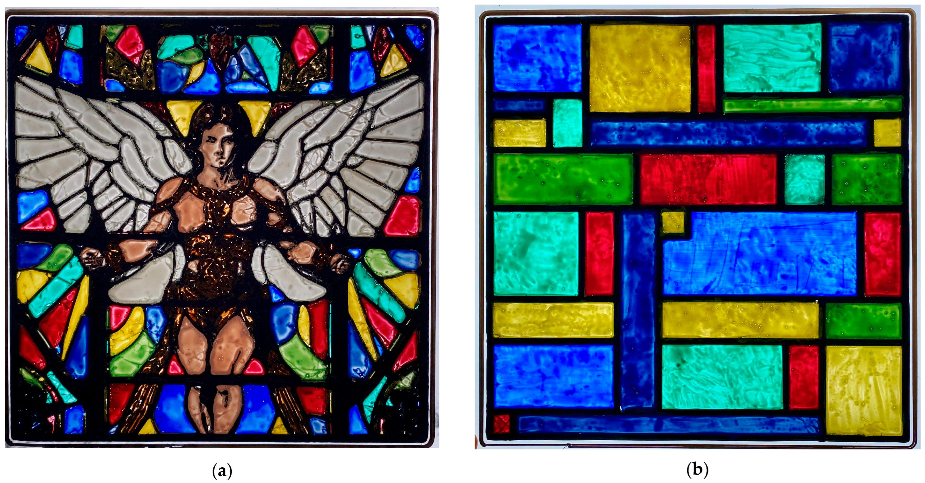
  • AI-generated patterns: novel custom design from an AI image generator (Angel, Figure 2e), saved as a raster image and converted into vector.
Finally, an additional vector image of a rectilinear geometric shape was made to quantify the total light transmission of PC-stained-glass windows obtained following the proposed methodology (Figure 2f).
The specifications of the six sample designs are summarized in Table 1. Each sample design image was made or modified considering square PC sheets with a 92,900 mm2 (1 ft2) area as substrates and a maximum 3D printable volume of 254 × 254 × 1.3 mm (10 in by 10 in × 0.05 in) for the 3D-printed sample parts. The 3D mesh models of the six sample designs were saved as STL files to define the 3D shape to be fabricated, whereas gcode files were used as the main file format for 3D printing.

2.1.1. Online-Retrieved Patterns

A classic design already digitally available as a 3D mesh model was selected as a first sample design (SG01), i.e., the Rose Window on the Notre Dame Cathedral [52] (Figure 2a). This 3D model has an overall height of 10 mm, which can cause warping of thin PC sheets during the 3D printing and is not required for 3D-printed stained-glass fabrication. For these reasons, this 3D model design was processed as a raster 2D image, as would most other 3D designs found on the Internet not specifically made for this application. A vector logo design was selected as a second sample design (SG02) from already available images, i.e., the Western University Free Appropriate Sustainability Technology (FAST) Laboratory logo [53] (Figure 2b). In both cases, images were processed using the open-source raster graphic image editor GNU Image Manipulation Program (GIMP) v 3.0.2 [54]. The images were cropped, and the color was removed using a paint bucket and auto-select tools, so the images were converted into black and white images and then saved as raster JPG files. The images were then imported into the open-source vector graphic image editor Inkscape v 1.4.2 (Inkscape, Boston, MA, USA) [55], where they were turned into vectors and saved as SVG files by using the “Trace bitmap” option according to the parameters shown in Table 2. This conversion into vector formats allows for high-quality images with better scalability, defined lines, and edges when resized according to the substrate dimensions. Furthermore, vector formats are easy to edit and manipulate when converted into 3D models for CAD software.

2.1.2. Custom Patterns: Digital-Drawn and Hand-Drawn Images

Digital drawings were prepared for the third sample design (SG03) using the open-source painting software Krita [56]. The digitally hand-drawn image of the Northern lights was saved as a JPG file. Then, it was imported into Inkscape and turned into a vector SVG file (Figure 2c) by creating paths with the same settings as in Table 2.
A hand drawing of a Viking ship was made using traditional drawing techniques for the fourth sample design (SG04), i.e., a graphite pencil on paper. The pencil drawing was retraced with a Sharpie marker to make the lines more visible for digital acquisition and match the stained-glass aesthetics and formal language. The drawing was then photographed with a camera phone and saved as a JPG file. The image was cropped and edited using GIMP to make it monochromatic as well as improve the contrast and maximize the black point high, increasing the accuracy of the vector conversion. As for the previous designs (Section 2.1.1), the designed pattern was processed into a vector SVG file (Figure 2d) using the parameters summarized in Table 2.

2.1.3. AI-Generated Pattern

The AI-generated image was created as a fifth sample design (SG05) using the open-source generative AI software Stable Diffusion A1111 v 1.10.1 [57] with the prompt for a clear stained glass image of an angel. The raster JPG image was then turned into a vector SVG file (Figure 2e) by creating paths with Inkscape according to the settings of Table 2. The AI-generated JPG image was intentionally used in its original version without modifying or correcting the original shape.

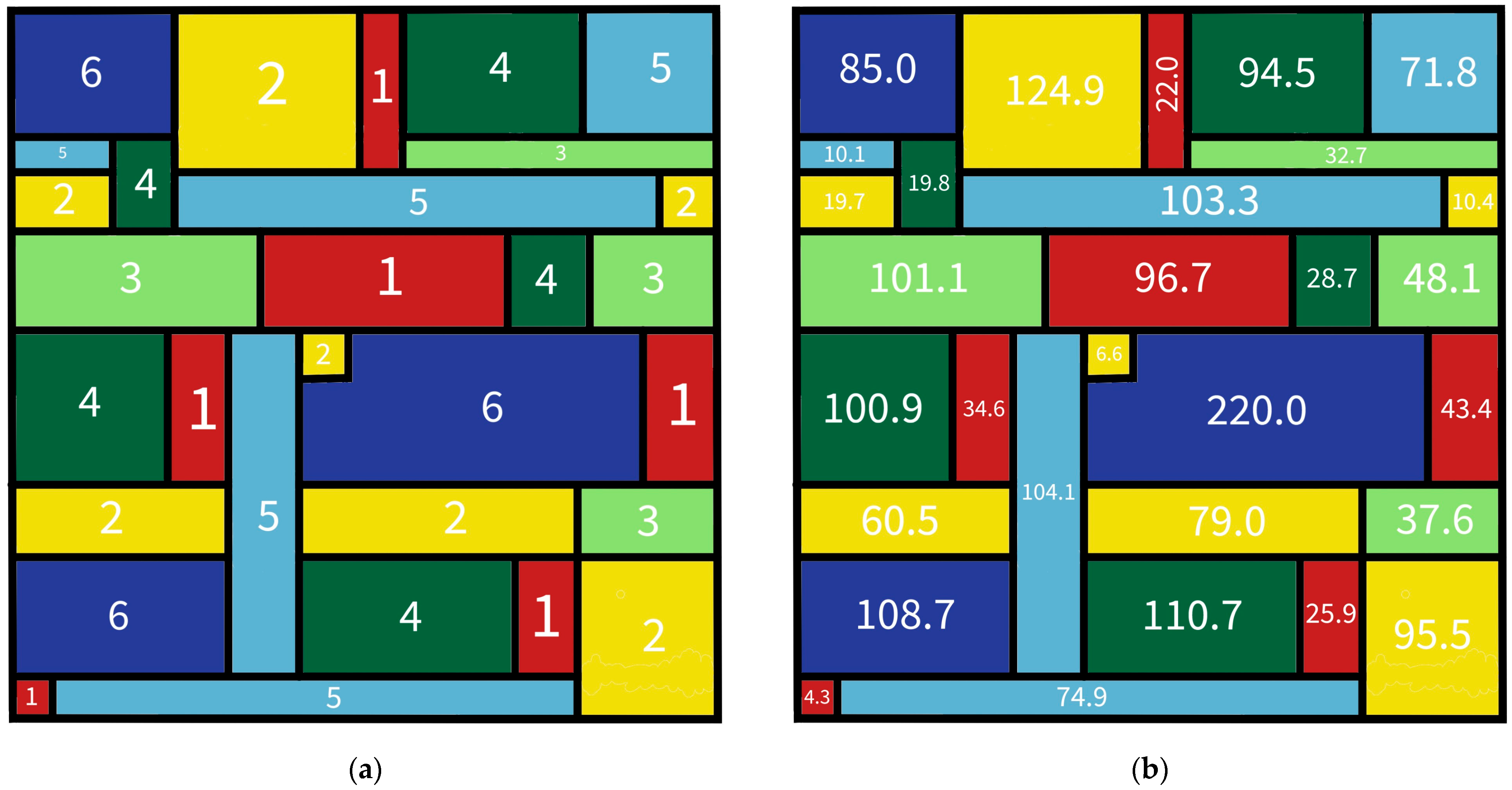
2.1.4. Geometric Validation Image

A rectilinear geometric shape image with known rectilinear sizes, 254 × 254 mm, was created as a sixth sample design (SG06) to validate the whole methodology and perform the optical spectra and transmission characterization. This validation image was intended to calculate the total transmission of a stained glass window with different colors and shapes through the open-source software ImageJ v 1.54 [58]. A geometrical pattern made of rectangular shapes was designed to facilitate the calculation of the painted and 3D-printed areas for the total optical transmission of the painted stained-glass part and double-check the data from ImageJ (Section 2.4). Consistent with the previous sample patterns, the design was saved as a vector SVG file (Figure 2f) using the parameters detailed in Table 2.

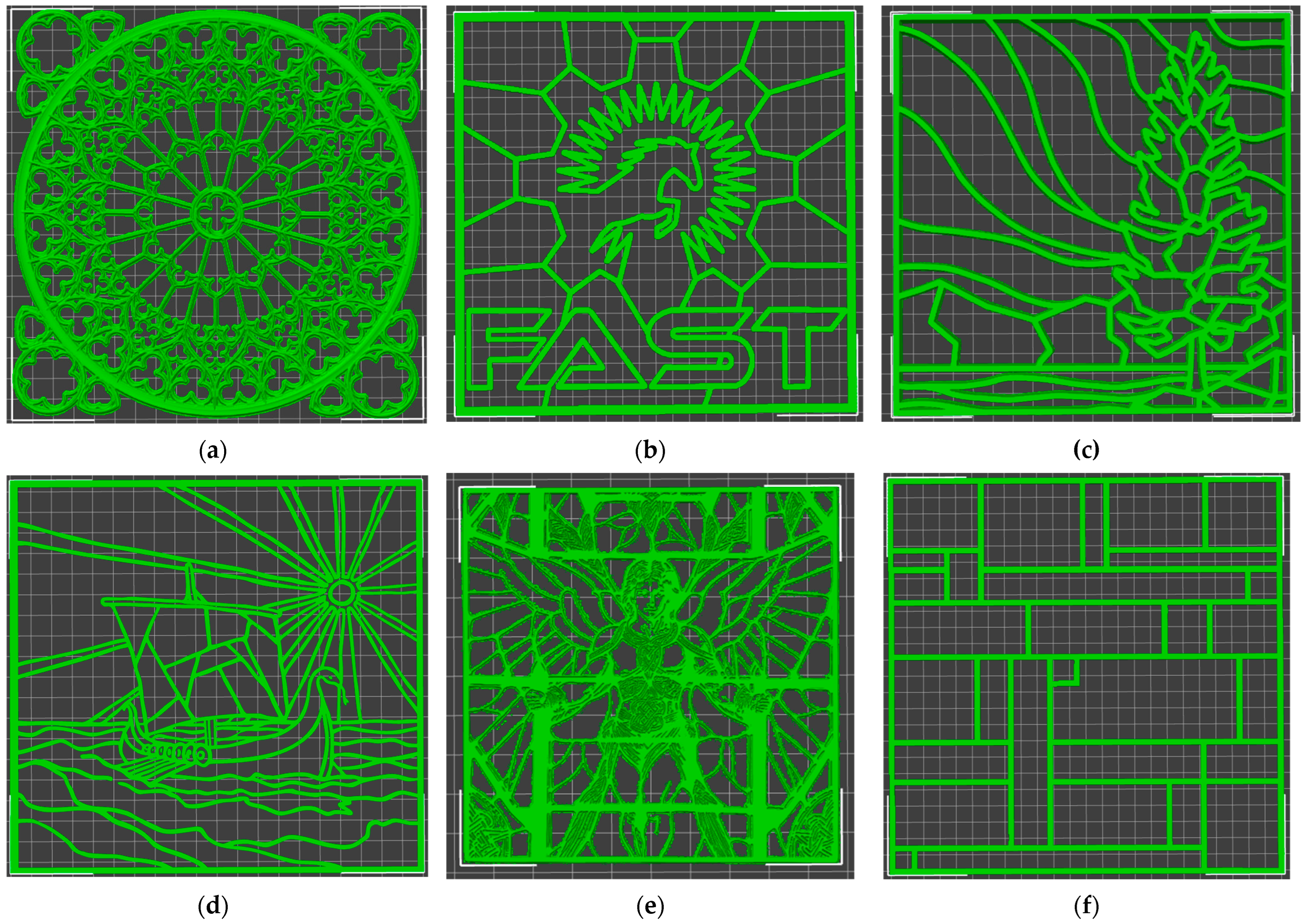
2.2. Phases 2 and 3: Creation of the 3D Mesh Models and 3D Printing Slicing

The SVG files of the six sample designs were imported into the open-source slicing software PrusaSlicer v 2.9.0 (Prusa Research, Prague, Czech Republic) [59] and scaled down to the size requirements of the experimental 3D-printable PC sheets, i.e., 254 × 254 × 1.3 mm. In detail, PrusaSlicer allows the conversion of an SVG file into an extrusion-like 3D mesh model through the option “Import STL/3MF/STEP/OBJ/AMF…” (Import menu) or by drag and drop, where the vector file is the starting vector shape. The user can then adjust the desired scale, position, and thickness of the 3D pattern and export it as a 3D mesh model, i.e., STL file, through the option “Export plate as STL/OBJ…” (Export menu). The specific dimensions and thicknesses of the six sample designs were saved by exporting the patterns as STL files, facilitating their replicability.
The main 3D printing slicing settings and parameters of the sample designs are summarized in Table 3. In the slicing settings, the nozzle was set at 1.2 mm instead of the 0.8 mm nozzle on the 3D printer to ensure an over-extrusion of 50% and no internal voids between the 3D-printed paths. The designs were sliced to a maximum height of 1.3 mm to prevent warping and match the aesthetic and formal language of stained glass. This z-axis height of the 3D model also limited the maximum number of layers to two, reducing the 3D printing times, material usage, and costs. The sample patterns were then exported as gcode and STL files (Figure 3) for the 3D printing process.

2.3. Phases 4 and 5: FFF Additive Manufacturing and Painting

The gcode files were used to fabricate the PC-based 3D design on the PC substrate via FFF 3D printing. An open-source large-format Modix BIG-Meter FFF 3D printer (Modix GmbH, Koblenz, Germany) [60,61] was used to 3D print the customized stained-glass designs with black PC filament (CC3D, Hangzhou Zhuopu New Materials Technology Co., LTD, Hangzhou, China) [62]. The six designs were 3D printed on 304.8 × 304.8 mm PC sheets (Plastic World, North York, TO, Canada) used as substrates, corresponding to an area of 92,900 mm2 (one square foot) [63]. Before the 3D printing process, the PC sheets were secured to the 3D printing bed with duct tape, and the starting z-height was set at the thickness of the sheet, which means 3 mm. The auto-bed-detection thus started the 3D print at just the surface of the PC sheet instead of the regular z-axis value of the first layer, i.e., 0.5 mm (Table 3). In this way, the hotend melted some of the top surfaces of the sheet during the 3D printing process, providing a complete bond between the 3D-printed PC filament and the clear PC substrate.
The parts were removed from the 3D printing bed, and the 3D-printed patterns were then post-processed to remove any residue material from the process, e.g., minor stringing from complex paths with significant use of retraction. The clear areas delimited by the 3D-printed pattern were colored with a 1:1 ratio of paint to water using acrylic paints (Castle Arts Supplies Ltd., Newcastle, UK, and Shuttle Art, Hangzhou, China). Acrylic paints were selected for their well-known good UV stability, matching the intended application. Paints were manually applied using paint brushes to keep the process accessible to end-users. The painted stained-glass parts were then dried at room temperature for 1 h before further characterization analyses. The finished sample parts underwent no additional post-processing or pigment treatment after painting.

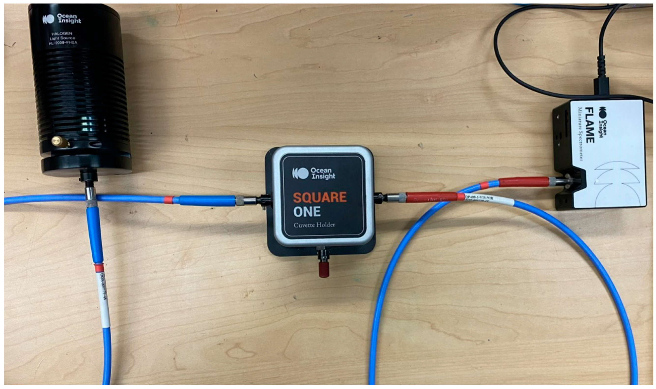
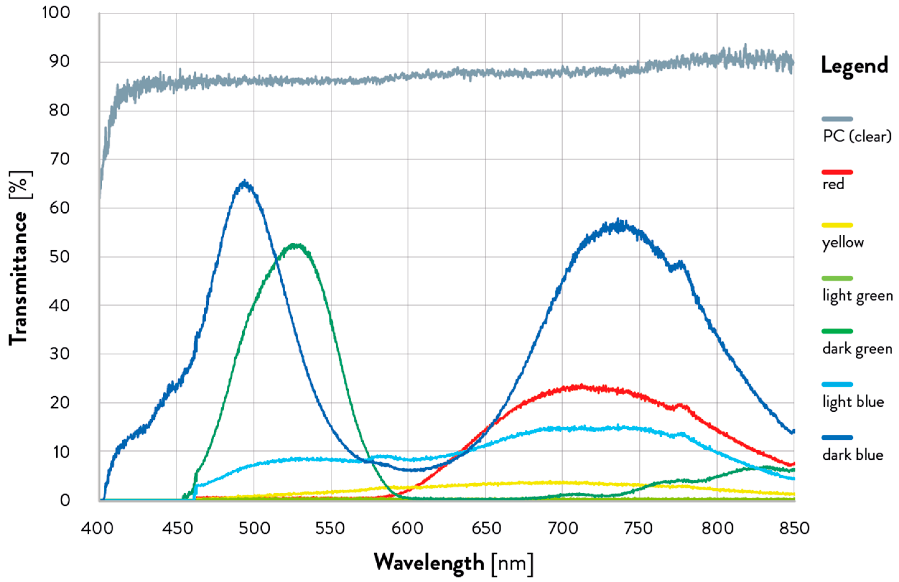
2.4. Optical Spectrum Characterization and Transmission Calculation

The stained-glass sample design of the geometric validation pattern (SG06) was used for the optical characterization to validate the presented methodology. This sample was used to perform optical spectrum measurements by means of a custom optical setup (Figure 4) with fiber optic cables coupling: (i) an Ocean Insight HL-2000-FHSA Halogen Light source (Figure 4, left), which was used to illuminate samples held in (ii) an Ocean Insight Square One Cuvette holder (Figure 4, center), and (iii) an Ocean Insight FLAME Spectrometer (Ocean Optics, Figure 4, right) to measure the transmitted light.
The optical transmission of the colored PC sheets was measured from 200 nm to 1040 nm to determine the optical transmission of the acrylic paints. Data were then plotted from 400 nm to 850 nm to focus the analysis on the visible spectrum region and the first portion of the near-infrared spectrum, according to the application studied in this work. A blackout and full light calibration spectra were run to set up the spectrometer. The transparent PC squares were then placed on the light side flush with the side of the cuvette hole to obtain the spectral transmission of the 3 mm thick PC, which was 87.3. This procedure was repeated for the painted PC squares of each of the six colors used for validation, i.e., red, yellow, light green, dark green, light blue, and dark blue. Ocean View software was used to control the spectrometer and process measurements (Ocean Optics, Gamble Technologies Limited, Mississauga, ON, Canada) [64].
The total optical transmission of the painted stained glass sample design (SG06) with different colors was calculated using ImageJ. The optical transmission for any multi-colored window can be given according to Equation (1):
T = n = 1 C t n a n n = 1 C a n ,
where t is the transmission of color n, a is the over area n, and C is the total number of colors. To test the ability of the image analysis software ImageJ to quantify the area of the colored regions in a PC-based stained-glass image, the geometric calibration pattern (SG06) shown in Figure 2f is used and colored according to the scheme of Figure 5. In detail, Figure 5a shows the color codes, where 1 is red, 2 is yellow, 3 is light green, 4 is dark green, 5 is light blue, and 6 is dark blue, whereas Figure 5b shows the known area in mm2 for each of the colored regions.
For the example of Figure 6, the total transmission is thus given from Equation (2):
T = t 1 a 1 + t 2 a 2 + t 3 a 3 + t 4 a 4 + t 5 a 5 + t 6 a 6 a 1 + a 2 + a 3 + a 4 + a 5 + a 6 + a p
where the six colors used in SG06 are taken into account and a p is the area of the black 3D-printed PC lines with an optical transmission of 0%. The experimental data are available in the OSF repository [51].

2.5. Preliminary Economic Analysis

A preliminary economic analysis of the 3D-printed PC stained-glass alternatives was performed on the six sample designs to validate their suitability in real-world distributed manufacturing contexts, e.g., developing countries. The analysis was performed according to Wittbrodt et al. [65], including materials and fabrication costs from electricity. The 3D printing times and costs were quantified considering the fabrication of the geometric design as an example of a possible design, starting from the nominal times and weights reported from the slicing in PrusaSlicer. The nominal weight was calculated assuming an average density of 1.2 g/cm3 for the 3D-printed PC feedstock, whereas the cost was USD 19.32/kg of filament [62]. According to the producer, an average power consumption of 1650 W was considered for fabricating the 3D-printed PC path on the selected large-format Modix 3D printer [60], i.e., 1370 W for the heated bed and 280 W for the 3D printer electronics, with an average electricity cost of USD 0.088, extracted from the mid-peak price period datasheet of the Ontario Energy Board [66]. The cost of PC sheets was USD 4.20/m2 for batches lower than 100 m2 [67], whereas a low-cost acrylic paint set of the selected brand cost about USD 22. The calculations are available in the OSF repository [51].

3. Results and Discussion

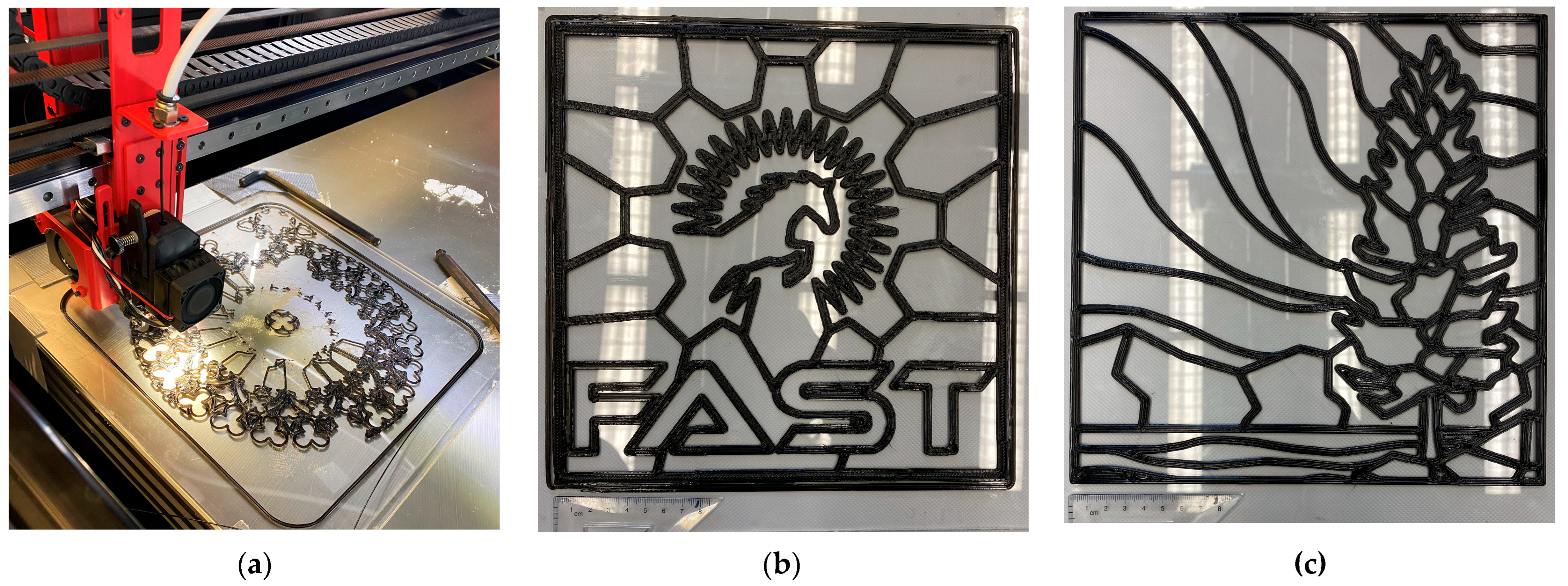
3.1. FFF Additive Manufacturing of the Sample Designs

Figure 6 shows the 3D-printed PC-based stained-glass designs obtained from the FFF 3D printing process (Section 2.3). The different sample designs (Table 1) were successfully fabricated by using the 3D printing parameters reported in Table 3. The overall quality of the 3D-printed paths is satisfactory for all the samples, without internal voids in the 3D-printed paths made of multiple perimeters. No warping or local delamination was detected during the 3D printing and cooling times. This fact indicates the good quality of the bonding between the PC substrate and the 3D-printed PC paths thanks to the bonding method described in Section 2.3, i.e., partial melting of the substrate thanks to the partial contact of the hotend 3D printing toolpath and the substrate (Figure 6a). On the one hand, this choice helped increase the durability of the connection between the 3D-printed part and the substrate. On the other hand, it might decrease the accuracy of the 3D-printed patterns by increasing the width of the first layer lines, also known as the “elephant foot” effect, e.g., SG02 (Figure 2b, Figure 3b and Figure 6b). This feature can be easily adjusted by modifying the original line width of the 2D image and 3D mesh model, especially for custom vector patterns made by the user.
The online-retrieved patterns (SG01 and SG02) showed different results in terms of quality, also connected with their original image format, i.e., raster (SG01) and vector (SG02), and the resulting 3D mesh models. The former design (Figure 6a) has intricate patterns, less homogeneous line thicknesses, and uses different widths to reproduce complex details, e.g., the trefoil and quatrefoil shapes in the middle, requiring different retractions and toolhead non-printing travels to be achieved, increasing the stringing effect and the overall 3D printing times. The latter (Figure 6b), a vector logo file, has less intricate patterns and similar thicknesses, which can be easily fabricated with fewer retractions and toolhead non-printing travels. The custom patterns (SG03 and SG04) showed the highest accuracy and 3D printing quality thanks to the use of lines with consistent widths during the drawing phase, resulting in uniform widths of the 3D-printed paths, as visible in Figure 6c,d. The AI-generated design (SG05) showed the same issues as SG01 in terms of the width of the 3D-printed paths, especially visible from the solid black PC areas of the last top layer (Figure 6e). This result is in line with the original format of the 2D image, i.e., raster, and its different formal language, which has big black drawing portions and very small intricate details not suitable for the selected nozzle diameter of 0.8 mm (Figure 2e). Finally, the geometric validation image (SG06) reached accuracy levels comparable to the custom patterns, in line with the homogeneous line width used for its realization.
These qualitative results show the feasibility of 3D printing design patterns with different shape and geometry complexity. They also highlight the need for optimized 3D path designs to achieve optimal results, i.e., reduced stringing and increased shapes and line width accuracy, requiring approaches toward DfAM. As suggested by works on tunable 2D paths for 3D printing [47,48], the conversion of the 2D patterns into 3D printing paths can be optimized to reduce the creation of shape defects from the approximation due to the nozzle diameter and movement path generation, e.g., controlling their width and the distance between the lines. The 3D printing quality of the patterns can also be improved by using different nozzle diameters to fabricate different line widths of the 2D image, especially when using a multi-toolhead or dual-extruder 3D printer such as the Modix. For instance, the 3D mesh model can be divided into two separate portions, each assigned to a specific hotend mounting different nozzle sizes, e.g., 1.2 or 0.8 mm for the main paths and 0.4 mm for fine details. This choice can also increase the aesthetic possibilities achieved by 3D printing stained-glass alternatives, increasing the potential uses by applying DfAM principles.

3.2. Fabrication of Stained-Glass Patterns

3.2.1. Online-Retrieved Patterns

Figure 7a shows the painted stained-glass alternative of the Rose Window on the Notre Dame Cathedral design (SG01). As can be seen in the image, the non-uniform effect of using the watered-down acrylic paint creates an authentic-looking old-colored glass effect. As the design has a high fraction of dark blue and red, the overall transparency of the window is also high. This fact is because the dark blue and red paints have no white in their solutions, making the colors less opaque. Figure 7b shows the finalized image of the FAST lab logo (SG02), which was painted in purple tones according to the Western University color palette. This first approach demonstrated the feasibility of using already available 2D images as 3D printing patterns for stained glass alternatives.

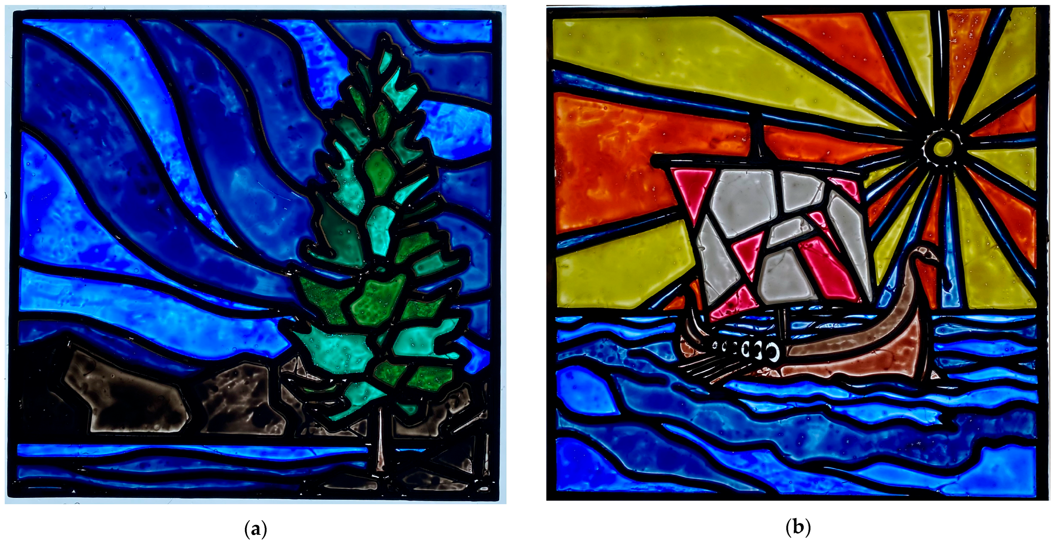
3.2.2. Custom Patterns: Digital-Drawn and Hand-Drawn Images

Figure 8 shows the two hand-drawn stained glass sample designs made as custom patterns after painting. Figure 8a shows the digitally hand-drawn painting of the Northern lights, while Figure 8b shows the results from the digitally acquired sketch of the Viking ship, photographed and post-processed to ensure consistent line widths. This approach showed the ability to customize stained-glass alternatives according to specific user patterns, increasing the potential options for 3D-printed stained glass.

3.2.3. AI-Generated Pattern and Geometric Validation Image

Figure 9a shows the AI-generated sample design after painting (SG05), showing a further potential way to customize 3D-printed stained-glass alternatives. This solution can be useful for users: (i) unable to find already available images on the Internet matching their needs; (ii) without adequate artistic, technical, or design skills; or (iii) without enough time to design their own design patterns. Despite some imperfections in the generated pattern, e.g., anatomical inaccuracies, AI-generated images can enlarge the uses of the proposed design methodology, especially if matched with accurate anatomically oriented training and corrective post-processing. Open-source AI generation tools like Stable Diffusion can also be used to make new patterns using appropriate and detailed prompts. Lastly, basic geometric patterns (SG06, Figure 9b) can also be customized using vector software without significant sketching or artistic drawing skills. This third approach can pave the way to further open the stained-glass fabrication of custom and complex geometries thanks to digital fabrication.

3.3. Optical Transmission Validation

The optical characterization was performed on the painted geometric validation pattern (SG06) to validate the methodology presented in this work. The optical transmission as a function of wavelength for the six color hues selected for the validation study is shown in Figure 10. According to Table 4, the dark blue hue had the highest light transmission peaks in the visible region (400–750 nm), i.e., 21.3%, whereas the lowest transmission values were observed in the light green and yellow hues, i.e., 0.1 and 1.7%. Dark green, red, and light blue hues also reached low transmission values according to the values, i.e., ranging from 6.9 to 7.6%. This fact is because of substantial fractions of white pigment in the formulations of light color hues, e.g., titanium dioxide, which can scatter or absorb the light transmission, resulting in more opaque painted colors despite their light tones and the clear substrate [68]. Some hues exhibited sharp drops in the transmission in the 500–600 nm and 700–800 nm regions, i.e., dark blue, dark green, and red, which can be due to the specific pigment spectral behavior from their formulation. Light colors show smoother transmittance curves without significant peak drops, i.e., yellow and light blue, or with a flat profile, such as for the light green hue. Furthermore, the presence of UV-blockers in the acrylic formulations to improve the UV resistance of the paints can justify the low light transmittance values close to 400 nm, then recovered in the visible region. This behavior is also visible in the clear PC substrate, which is known for its UV resistance. Although the acrylic-painted PC stained glass uses different coloring ways than traditional techniques, these results can be used for a preliminary assessment of the method, helping optimize the painting procedure according to the desired color and light perception, e.g., water mixing ratio, number of painting layers, or hue mixing.
The finalized geometric design used for validation (Figure 9b) was then used to calculate the total optical transmission of a complete sample design painted stained glass, including the 3D-printed PC black design patterns. The areas of the colored regions were all calculated from the digital design (SG06) and verified with calipers to test the accuracy of the ImageJ analysis. As shown in Table 4, the values provided by ImageJ are within rounding error for all regions, e.g., 0.1 mm2. ImageJ can, therefore, provide good accuracy for evaluating area fractions on more complicated patterns. It can then be used to evaluate the total optical transmission of painted 3D-printed stained glass using the general equation for optical transmission (Equation (1)), further supporting the fully open-source toolchain. The measurements were repeated three times for each pigment to ensure the repeatability of the procedure, but no significant differences or variations were observed. According to Equation (2), the total transmittance of the geometric design (SG06) shown in Figure 9b is 6.46%, strongly influenced by the 3D-printed black PC patterns (came alternatives). As for the previous optical characterization, this assessment can be used to design geometry patterns and paint color combinations to achieve specific requirements, e.g., daylight-transmitting surfaces or smooth-colored light diffusion. This approach allows for flexibility in the design of the stained-glass alternatives by tuning the proportions of 3D-printed black frames, clear PC, and painted surfaces.

3.4. Economic Analysis

A preliminary economic analysis of the stained-glass PC sample designs was performed to validate its suitability in real-world distributed manufacturing contexts, such as developing countries, including the base material and energy consumption costs. The 3D printing weights, times, and costs were quantified for the six sample designs, starting from the nominal times reported from the slicing in PrusaSlicer, as shown in Table 5. The different design patterns required less than 1 h to be fabricated, whereas the geometric design (SG06) took about 20 min of 3D printing time to fabricate. The primary cost was the PC filament for 3D printing, with average weights of 20–30 g and costs of USD 0.40–0.60 in most cases. For instance, the geometric validation sample (SG06) used 21 g of PC filament, which costs USD 19.32/kg [62], so the filament cost was about USD 0.41. Energy costs represent a minimal percentage of the overall costs to fabricate the 3D-printed glass sample designs. Previous work on distributed manufacturing using open-source 3D printers has already shown that the electrical costs of 3D printing are greatly exceeded by the cost of filament [31]. The analysis further confirmed it, reaching average values of USD ~0.10 despite the significant impact of the heating bed on the energy consumption of large-format 3D printers [60,69].
The secondary cost is the PC sheet. Small batches of PC sheets (>100 m2) can be obtained for USD 4.20/m2 [67], which makes the PC experimental sheet cost about USD 0.39. The paint was estimated to cost only a few pennies for each sample, hence negligible in this analysis. Thus, the total material cost per square foot is around USD 11–12/m2 (USD ~1/ft2). For comparison, the cost of a standard double pane window is USD 50/m2 (USD 4.64/ft2) [70], and stained glass, as noted earlier, costs USD 6372/m2 (USD 592/ft2). Thus, this approach reduces the material and energy costs for stained glass as an alternative by more than a factor of ~50, with significant differences between parts with optimized 3D printed paths, e.g., SG04, and patterns created without the same optimization, such as the AI-generated sample (SG05).

3.5. Potential of 3D-Printed Stained-Glass Alternatives Fabricated Through Open-Source Approaches

The results of this study demonstrated a new open-design approach to obtaining stained-glass alternatives using a fully open-source toolchain made up of open-source software and open-hardware-based AM. This methodology can be applied to different 2D images and 3D mesh models, generating customized stained-glass patterns from online-retrieved files found on the internet, as well as novel custom design patterns, either developed natively in digital media or digitally acquired from hand-drawn images on paper. In addition, open-source AI image generators can be used to create stained-glass patterns. These approaches, as well as the whole methodology, provide an accessible and flexible way to add or replace stained-glass windows with a (i) thermally superior, (ii) low-cost, and (iii) customizable PC-based stained glass alternative available to a broader range of users and customers.
This application of 3D printing is in line with other work that has applied AM technologies for buildings and cultural heritage [71]. Current AM applications include the conservation and restoration of architectural structures, artworks, and cultural artifacts, e.g., columns or sculptures [72,73], as well as the design and development of entirely new artifacts, products, and artworks [74]. Among these, first attempts in partially or fully 3D-printed stained-glass-like parts have been emerging recently, ranging from small do-it-yourself samples [75] and hybrid crafts with colored epoxy casting into 3D-printed cames [76] to commercial 3D-printed clear resin windows mounted into 3D-printed frames after painting [77]. To this end, the open-design methodology presented in this work can support the real implementation of stained-glass alternatives in different contexts, adapting to the user’s needs. Specifically, broken stained-glass windows to be replaced could be replicated using a PC substrate and inserted directly into the window opening or as part of a sandwich with a conventional clear window. In addition, new stained glass windows could be designed to be used in cultural buildings and public spaces or as part of new products or hybrid craft practices [14]. Existing historical designs can also be replicated in different geographical contexts, either for replicative or educational purposes, taking advantage of the distributed nature of AM technologies. Completely new parts and products can also be designed by the users and fabricated following the presented methodology, supporting design-thinking approaches amongst users through open source. Lastly, using secondary raw materials from scraps and byproducts can pave the way to distributed 3D-printed stained-glass alternatives from locally recycled feedstocks, following the principles of distributed recycling for additive manufacturing (DRAM) [44,78]. These materials are currently used to fabricate several products with large-format 3D printers, including architectural elements and artistic artifacts [79]. Stained-glass alternatives can, therefore, further enlarge the available applications in real-world scenarios, e.g., specific geographical or low-resource settings.
The rectilinear geometric shape-related analysis successfully demonstrated that open-source ImageJ software can be effectively utilized to quantify the areas of stained glass for quantitative evaluations. As shown in the previous sections, these areas can be coupled with measured optical spectral transmission measurements to gain complete transmission values of full stained-glass window alternatives with more complex shapes and patterns. This achievement can help design custom patterns according to the desired needs, e.g., specific transmission and diffusion of the window, changes in the ratios between the black frames and the painted clear PC, or adjustments in the painting mixing and procedures. The total optical transmission values found show substantial promise for PC-based stained-glass windows to reduce solar heat gain coefficients for windows everywhere, but most importantly in areas with substantial cooling loads.

3.6. Limitations and Future Work

This research presents some limitations to be further studied in future work. For instance, the experimental work did not include a quantitative assessment of the bonding between the PC substrate and 3D-printed paths. Future research can, therefore, study the adhesion of the 3D-printed parts onto the substrate, e.g., through pull-off tests. Similarly, the dimensional accuracy of the 3D-printed paths should be investigated through quantitative measurements, e.g., comparing the nominal and actual line widths through imaging with ImageJ. This analysis can also be matched with the optimization of the design and fabrication of the 3D printing paths to increase the shape accuracy of complex geometrical shapes while decreasing retractions, travel movements, and 3D printing times, according to DfAM principles. The durability of the pigments and acrylic paints used for the sample designs was not assessed after medium- or long-term environmental exposure. Despite the good UV resistance of acrylic paints [80,81], future analyses are needed to assess their durability for the intended application when facing outward. For instance, accelerated weathering tests can assess the aging of acrylic paints after environmental exposure, e.g., humidity and UV. Abrasion and adhesion tests can evaluate the durability of the acrylic coating combined with the substrate. Another limitation of this study was the exclusion of labor for the economic analysis, which only attempted to quantify material and energy consumption costs. The results of the economic analysis showed that PC-based stained-glass alternatives have the potential to cut that price by a factor of 50. Labor costs would include the labor to set up the 3D printing process (minor), as well as to color the PC, which could be substantial depending on the labor costs. Thus, the labor costs may be more expensive than the equipment. The energy efficiency of the proposed stained-glass alternative should also be evaluated to validate its use in different geographical and socio-economic contexts, and future work is needed to quantify the potential energy savings for such PC-based stained-glass window applications.
Additional work can be carried out to spread further the potential use of the proposed stained-glass alternatives. For instance, it is possible to use a multi-toolhead or multi-extruder 3D printer to fully 3D print stained-glass parts with translucent filaments of different colors [82]. This approach was not used here because of the current unavailability of translucent PC filaments. Thus, substantial future work is needed to develop such filaments using recycled PC and open-source waste plastic extruders, e.g., recyclebots [78,83]. Different nozzle diameters could also be matched in a single design pattern by means of multi-toolhead or dual-extruder 3D printers, assigning specific nozzle sizes to geometrical features with different line widths and intricate shapes, optimizing the fabrication process and enlarging the design flexibility. Another approach could be the Hueforge filament painting approach of 3D printing thin colored filaments that are effectively semi-transparent to make images [84]. In the future, using a multi-toolhead or multi-material 3D printer to deposit different filament colors on top of UV-stabilized PC sheets is an area to be explored for complete stained-glass replacements. There have been efforts to convert conventional images to stained-glass-like images using a combination of image warping, segmentation, querying, colorization, and texture synthesis [85]. This approach was used here with Stable Diffusion, as stained-glass images have also gained popularity with the AI-based art community [86]. Thus, if combined, future work could develop a completely integrated software package for file conversion. This option could allow users to convert a 2D image in a single step to a 3D model and color map file to be fully manufactured on an open-source 3D printer, including coloring, relying on a fully open-source toolchain and methodology.

4. Conclusions

This work explored open-source AM technologies to fabricate PC-based stained-glass alternatives for the building and heritage sectors, providing a way for customizable, low-cost, and thermally superior options compared to conventional products. It presented a new DfAM methodology for 3D-printable stained-glass alternatives based on design-thinking and open-design principles, i.e., using a fully open-source toolchain and integrating the user’s needs with technical requirements. Different design patterns were created through three approaches, representing possible starting points for the user’s customization, i.e., from online-retrieved 2D images or 3D models, custom digitalized or digital drawings, and AI-generated 2D images. The six sample designs were successfully fabricated using PC sheets as substrates for 3D-printed custom geometries made in PC, which were then painted with acrylic colors. The practical feasibility of the methodology was therefore demonstrated thanks to the design and fabrication steps and then validated through optical characterization with open-source software and preliminary economic analysis, highlighting the potential use of these alternatives in specific geographical and low-resource settings.
According to the results, different geometries can be fabricated with this approach, starting from different sources and formats of the 2D images, e.g., raster or vector files. The custom patterns and the vector image sources showed the best results in terms of 3D printing quality and accuracy of the intended shapes, allowing for the optimization of the drawing lines and resulting in optimized 3D printing toolpath generation, such as limited retractions and stringing from travel movements. Further optimization of the 3D printing paths can increase pattern fidelity and design flexibility, especially using multi-nozzle and toolhead 3D printers. Optical spectrum characterization of the painted stained glass showed different transmittance behaviors due to the acrylic painting hue. The total optical transmission could be estimated based on the specific geometry pattern and the distribution of the different colored and 3D-printed areas. This open-source evaluation can be used to customize stained-glass alternatives according to the desired light transmission and heat gain behaviors by tuning the 3D-printed pattern geometry design and the painting process. Finally, the economic analysis shows substantial cost reduction when using large-format AM technologies and PC as the main material, i.e., up to 50 times less expensive than traditional stained glass.
The proposed methodology shows potential for distributed and accessible applications in the building and heritage sectors, especially for repairing and replicating existing conventional stained glass and designing new customizable products. Despite the need for further work, initial results show potential application in climate environments to reduce solar heat gain coefficients and manufacturing costs while allowing for design flexibility and aesthetic customization. Future research should (i) deepen the characterization of the fabricated parts, e.g., the dimensional accuracy and bonding of the 3D printed path; (ii) explore multi-extruder and toolhead systems for automated coloring and intricated frame details; (iii) optimize the conversion of the 2D images into 3D printing paths; (iv) quantify the energy saving of the proposed stained-glass alternatives; and (v) explore alternative painting and protective coating techniques according to the specific context, e.g., airbrush with tape masking or transparent coatings for outdoor facing. Overall, the open-design methodology proposed in this work offers an accessible way to foster low-cost, customizable, and energy-efficient architectural and design applications for the building and heritage sectors in broader geographical and socio-economic contexts.

Author Contributions

Conceptualization, E.B.P. and J.M.P.; methodology, E.B.P., J.M.P., and A.R.; Software, E.B.P., J.M.P., and A.R.; validation, E.B.P. and A.R.; formal analysis, E.B.P. and A.R.; investigation, E.B.P.; resources, J.M.P.; data curation, E.B.P., J.M.P., and A.R.; writing—original draft preparation, E.B.P., J.M.P., and A.R.; writing—review and editing, E.B.P., J.M.P., and A.R.; visualization, E.B.P. and A.R.; supervision, J.M.P. and A.R.; project administration, J.M.P. and A.R.; funding acquisition, J.M.P. and A.R. All authors have read and agreed to the published version of the manuscript.

Funding

Funding for this work was provided by the Canada Foundation for Innovation, the Ontario Research Fund-Research Infrastructure program, the Natural Sciences and Engineering Research Council of Canada, and the Thompson Endowment.

Data Availability Statement

Acknowledgments

The authors would like to thank J. Givans for technical support.

Conflicts of Interest

The authors declare no conflicts of interest.

References

  1. Rosewell, R. Stained Glass; Bloomsbury Publishing: London, UK, 2012; ISBN 978-1-78200-150-8. [Google Scholar]
  2. Hunault, M.O.J.Y.; Bauchau, F.; Boulanger, K.; Hérold, M.; Calas, G.; Lemasson, Q.; Pichon, L.; Pacheco, C.; Loisel, C. Thirteenth-Century Stained Glass Windows of the Sainte-Chapelle in Paris: An Insight into Medieval Glazing Work Practices. J. Archaeol. Sci. Rep. 2021, 35, 102753. [Google Scholar] [CrossRef]
  3. Varieties of Stained Glass. Available online: https://stainedglass.org/learning-resources/varieties-stained-glass (accessed on 20 May 2025).
  4. Parker, J.M.; Martlew, D. Stained Glass Windows. In Encyclopedia of Glass Science, Technology, History, and Culture; John Wiley & Sons, Ltd.: Hoboken, NJ, USA, 2021; pp. 1341–1359. ISBN 978-1-118-80101-7. [Google Scholar]
  5. Finucane, M.A.; Black, I. CO2 Laser Cutting of Stained Glass. Int. J. Adv. Manuf. Technol. 1996, 12, 47–59. [Google Scholar] [CrossRef]
  6. Rehren, T.; Freestone, I.C. Ancient Glass: From Kaleidoscope to Crystal Ball. J. Archaeol. Sci. 2015, 56, 233–241. [Google Scholar] [CrossRef]
  7. Shields, D. Design in Stained Glass. Stud. Ir. Q. Rev. 1952, 41, 209–218. [Google Scholar]
  8. Yuan, M.; Bonet, J.; Cotte, M.; Schibille, N.; Gratuze, B.; Pradell, T. The Role of Sulphur in the Early Production of Copper Red Stained Glass. Ceram. Int. 2023, 49, 18602–18613. [Google Scholar] [CrossRef]
  9. Pradell, T.; Molina, G.; Murcia, S.; Ibáñez, R.; Liu, C.; Molera, J.; Shortland, A.J. Materials, Techniques, and Conservation of Historic Stained Glass “Grisailles”. Int. J. Appl. Glass Sci. 2016, 7, 41–58. [Google Scholar] [CrossRef]
  10. Verney-Carron, A.; Sessegolo, L.; Chabas, A.; Lombardo, T.; Rossano, S.; Perez, A.; Valbi, V.; Boutillez, C.; Muller, C.; Vaulot, C.; et al. Alteration of Medieval Stained Glass Windows in Atmospheric Medium: Review and Simplified Alteration Model. Npj Mater. Degrad. 2023, 7, 49. [Google Scholar] [CrossRef]
  11. Vilarigues, M.; Redol, P.; Machado, A.; Rodrigues, P.A.; Alves, L.C.; da Silva, R.C. Corrosion of 15th and Early 16th Century Stained Glass from the Monastery of Batalha Studied with External Ion Beam. Mater. Charact. 2011, 62, 211–217. [Google Scholar] [CrossRef]
  12. Corrêa Pinto, A.M.; Macedo, M.F.; Vilarigues, M.G. The Conservation of Stained-Glass Windows in Latin America: A Literature Overview. J. Cult. Herit. 2018, 34, 172–181. [Google Scholar] [CrossRef]
  13. Murcia-Mascarós, S.; Foglia, P.; Santarelli, M.L.; Roldán, C.; Ibañez, R.; Muñoz, A.; Muñoz, P. A New Cleaning Method for Historic Stained Glass Windows. J. Cult. Herit. 2008, 9, e73–e80. [Google Scholar] [CrossRef]
  14. Gagnon-King, D.; Jones, L.; Nabil, S. Interactive Stained-Glass: Exploring a New Design Space of Traditional Hybrid Crafts for Novel Fabrication Methods. In Proceedings of the Seventeenth International Conference on Tangible, Embedded, and Embodied Interaction, Warsaw, Poland, 26 February–1 March 2023; Association for Computing Machinery: New York, NY, USA, 2023; pp. 1–15. [Google Scholar] [CrossRef]
  15. Cuce, E.; Riffat, S.B. A State-of-the-Art Review on Innovative Glazing Technologies. Renew. Sustain. Energy Rev. 2015, 41, 695–714. [Google Scholar] [CrossRef]
  16. Somasundaram, S.; Thangavelu, S.R.; Chong, A. Improving Building Efficiency Using Low-e Coating Based Retrofit Double Glazing with Solar Films. Appl. Therm. Eng. 2020, 171, 115064. [Google Scholar] [CrossRef]
  17. Wolf, S.; Trümpler, S.; Wakili, K.G.; Binder, B.; Baumann, E. Protective Glazing: The Conflict Between Energy- Saving and Conservation Requirements. In Recent Advances in Glass, Stained-Glass, and Ceramic Conservation 2023, Amsterdam, Netherlands, 7–10 October 2013; SPA Uitgevers: Zwolle, The Netherlands, 2013; pp. 99–107. [Google Scholar]
  18. Uher, C. Thermal Conductivity of Metals. In Thermal Conductivity: Theory, Properties, and Applications; Tritt, T.M., Ed.; Physics of Solids and Liquids; Springer: Boston, MA, USA, 2004; pp. 21–91. ISBN 978-0-387-26017-4. [Google Scholar]
  19. Lidelöw, S.; Örn, T.; Luciani, A.; Rizzo, A. Energy-Efficiency Measures for Heritage Buildings: A Literature Review. Sustain. Cities Soc. 2019, 45, 231–242. [Google Scholar] [CrossRef]
  20. How Much Does Installing a Stained Glass Window Cost? Available online: https://www.homeadvisor.com/cost/home-design-and-decor/install-stained-glass/ (accessed on 16 June 2025).
  21. 2025 Stained Glass Window Cost. Available online: https://www.angi.com/articles/how-much-cost-stained-glass-window.htm (accessed on 16 June 2025).
  22. Stained Glass Repair Cost: Can Stained Glass Be Repaired and How Much Does It Cost?—Kompareit.Com. Available online: https://www.kompareit.com/homeandgarden/windows-can-stained-glass-be-repaired (accessed on 16 June 2025).
  23. Frenzel, G. The Restoration of Medieval Stained Glass. Sci. Am. 1985, 252, 126–137. [Google Scholar] [CrossRef]
  24. Qurraie, B.S.; Beyhan, F. Investigating the Effect of Stained-Glass Area on Reducing the Cooling Energy of Buildings (Case Study: Ankara). CRPASE 2022, 8, 2749. [Google Scholar] [CrossRef]
  25. Shaik, S.; Maduru, V.R.; Kirankumar, G.; Arıcı, M.; Ghosh, A.; Kontoleon, K.J.; Afzal, A. Space-Age Energy Saving, Carbon Emission Mitigation and Color Rendering Perspective of Architectural Antique Stained Glass Windows. Energy 2022, 259, 124898. [Google Scholar] [CrossRef]
  26. Golsteijn, C.; van den Hoven, E.; Frohlich, D.; Sellen, A. Hybrid Crafting: Towards an Integrated Practice of Crafting with Physical and Digital Components. Pers. Ubiquitous Comput. 2014, 18, 593–611. [Google Scholar] [CrossRef]
  27. Zoran, A. Hybrid Craft: Showcase of Physical and Digital Integration of Design and Craft Skills. In Proceedings of the ACM SIGGRAPH Art Gallery, Los Angeles, CA, USA, 9–13 August 2015; Association for Computing Machinery: New York, NY, USA, 2015; pp. 384–398. [Google Scholar] [CrossRef]
  28. Boisseau, É.; Omhover, J.-F.; Bouchard, C. Open-Design: A State of the Art Review. Des. Sci. 2018, 4, e3. [Google Scholar] [CrossRef]
  29. Moretti, E.; Zinzi, M.; Belloni, E. Polycarbonate Panels for Buildings: Experimental Investigation of Thermal and Optical Performance. Energy Build. 2014, 70, 23–35. [Google Scholar] [CrossRef]
  30. Chammas, A.; Quaresma, M.; Mont’Alvão, C. A Closer Look on the User Centred Design. Procedia Manuf. 2015, 3, 5397–5404. [Google Scholar] [CrossRef]
  31. Petersen, E.E.; Kidd, R.W.; Pearce, J.M. Impact of DIY Home Manufacturing with 3D Printing on the Toy and Game Market. Technologies 2017, 5, 45. [Google Scholar] [CrossRef]
  32. Attaran, M. The Rise of 3-D Printing: The Advantages of Additive Manufacturing over Traditional Manufacturing. Bus. Horiz. 2017, 60, 677–688. [Google Scholar] [CrossRef]
  33. Romani, A.; Rognoli, V.; Levi, M. Design, Materials, and Extrusion-Based Additive Manufacturing in Circular Economy Contexts: From Waste to New Products. Sustainability 2021, 13, 7269. [Google Scholar] [CrossRef]
  34. Obi, M.U.; Pradel, P.; Sinclair, M.; Bibb, R. A Bibliometric Analysis of Research in Design for Additive Manufacturing. Rapid Prototyp. J. 2022, 28, 967–987. [Google Scholar] [CrossRef]
  35. Sells, E.; Bailard, S.; Smith, Z.; Bowyer, A.; Olliver, V. RepRap: The Replicating Rapid Prototyper: Maximizing Customizability by Breeding the Means of Production. In Handbook of Research in Mass Customization and Personalization; World Scientific Publishing Company: Singapore, 2009; pp. 568–580. ISBN 978-981-4280-25-9. [Google Scholar]
  36. Jones, R.; Haufe, P.; Sells, E.; Iravani, P.; Olliver, V.; Palmer, C.; Bowyer, A. RepRap—The Replicating Rapid Prototyper. Robotica 2011, 29, 177–191. [Google Scholar] [CrossRef]
  37. Petersen, E.E.; Pearce, J. Emergence of Home Manufacturing in the Developed World: Return on Investment for Open-Source 3-D Printers. Technologies 2017, 5, 7. [Google Scholar] [CrossRef]
  38. Dreessen, K.; Schepers, S.; Leen, D. From Hacking Things to Making Things. Rethinking Making by Supporting Non-Expert Users in a FabLab. Interact. Des. Archit. 2016, 30, 47–64. [Google Scholar] [CrossRef]
  39. Greenhalgh, S. The Effects of 3D Printing in Design Thinking and Design Education. J. Eng. Des. Technol. 2016, 14, 752–769. [Google Scholar] [CrossRef]
  40. Pearce, J.; Qian, J.-Y. Economic Impact of DIY Home Manufacturing of Consumer Products with Low-Cost 3D Printing from Free and Open Source Designs. Eur. J. Soc. Impact Circ. Econ. 2022, 3, 1–24. [Google Scholar] [CrossRef]
  41. Bahar, A.; Belhabib, S.; Guessasma, S.; Benmahiddine, F.; Hamami, A.E.A.; Belarbi, R. Mechanical and Thermal Properties of 3D Printed Polycarbonate. Energies 2022, 15, 3686. [Google Scholar] [CrossRef]
  42. Vidakis, N.; Petousis, M.; Kechagias, J.D. A Comprehensive Investigation of the 3D Printing Parameters’ Effects on the Mechanical Response of Polycarbonate in Fused Filament Fabrication. Prog. Addit. Manuf. 2022, 7, 713–722. [Google Scholar] [CrossRef]
  43. Vidakis, N.; Petousis, M.; Velidakis, E.; Spiridaki, M.; Kechagias, J.D. Mechanical Performance of Fused Filament Fabricated and 3D-Printed Polycarbonate Polymer and Polycarbonate/Cellulose Nanofiber Nanocomposites. Fibers 2021, 9, 74. [Google Scholar] [CrossRef]
  44. Romani, A.; Levi, M.; Pearce, J.M. Recycled Polycarbonate and Polycarbonate/Acrylonitrile Butadiene Styrene Feedstocks for Circular Economy Product Applications with Fused Granular Fabrication-Based Additive Manufacturing. Sustain. Mater. Technol. 2023, 38, e00730. [Google Scholar] [CrossRef]
  45. Reich, M.J.; Woern, A.L.; Tanikella, N.G.; Pearce, J.M. Mechanical Properties and Applications of Recycled Polycarbonate Particle Material Extrusion-Based Additive Manufacturing. Materials 2019, 12, 1642. [Google Scholar] [CrossRef] [PubMed]
  46. Yang, J.; He, S.; Lu, L. Binary Image Carving for 3D Printing. Comput.-Aided Des. 2019, 114, 191–201. [Google Scholar] [CrossRef]
  47. Chen, Z.; Chen, W.; Guo, J.; Cao, J.; Zhang, Y.J. Orientation Field Guided Line Abstraction for 3D Printing. Comput. Aided Geom. Des. 2018, 62, 253–262. [Google Scholar] [CrossRef]
  48. Bedel, A.; Coudert-Osmont, Y.; Martínez, J.; Nishat, R.I.; Whitesides, S.; Lefebvre, S. Closed Space-Filling Curves with Controlled Orientation for 3D Printing. Comput. Graph. Forum 2022, 41, 473–492. [Google Scholar] [CrossRef]
  49. Powell, A. Democratizing Production through Open Source Knowledge: From Open Software to Open Hardware. Media Cult. Soc. 2012, 34, 691–708. [Google Scholar] [CrossRef]
  50. Gibb, A. Building Open Source Hardware: DIY Manufacturing for Hackers and Makers; Addison-Wesley Professional: Boston, MA, USA, 2014; ISBN 978-0-13-337390-5. [Google Scholar]
  51. Bow Pearce, E.; Pearce, J.; Romani, A. 3D Printable Designs for Alternatives to Stained Glass for Energy Efficiency and Economic Savings. Available online: https://doi.org/10.17605/OSF.IO/WQ5PF (accessed on 28 May 2025).
  52. NOTRE DAME. 3D CAD Model Library on GrabCAD. Available online: https://grabcad.com/library/notre-dame-4 (accessed on 16 June 2025).
  53. FAST Logo Black and White. Available online: https://www.appropedia.org/File:FASTlogobw.png (accessed on 16 June 2025).
  54. GIMP—GNU Image Manipulation Program. Available online: https://www.gimp.org/ (accessed on 16 June 2025).
  55. Inkscape—Draw Freely. Available online: https://inkscape.org/ (accessed on 16 June 2025).
  56. Krita: Digital Painting. Creative Freedom. Available online: https://krita.org/en/ (accessed on 16 June 2025).
  57. AUTOMATIC1111 Stable Diffusion Web UI 2022. Available online: https://github.com/AUTOMATIC1111/stable-diffusion-webui (accessed on 29 May 2025).
  58. ImageJ. Available online: https://imagej.net/ij/ (accessed on 16 June 2025).
  59. PrusaSlicer—Firmware & Downloads. Available online: https://help.prusa3d.com/downloads/prusaslicer?versions=all (accessed on 16 June 2025).
  60. BIG-Meter—Modix Large 3D Printers. Available online: https://www.modix3d.com/big-meter/ (accessed on 5 May 2025).
  61. Operating Manual for Modix Printers. Available online: https://www.appropedia.org/Operating_Manual_for_Modix_printers (accessed on 17 May 2025).
  62. PC Filament 1.75 Mm 3D Printer Filament—CC3D. Available online: https://cc3dglobal.com/product/white-pc-filament-1-75-mm-3d-printer-filament/ (accessed on 16 June 2025).
  63. 20 Pack 12 x 12 x.02 Inch Clear Plastic Craft Polycarbonate Sheet Thin Clear Plastic Sheet Flexible Transparent Plastic Sheet. Available online: https://www.amazon.ca/Polycarbonate-Flexible-Transparent-Projects-Replacement/dp/B09XZZG8SH (accessed on 16 June 2025).
  64. Software, Ocean Optics. Available online: https://www.oceanoptics.com/software/ (accessed on 16 June 2025).
  65. Wittbrodt, B.T.; Glover, A.G.; Laureto, J.; Anzalone, G.C.; Oppliger, D.; Irwin, J.L.; Pearce, J.M. Life-Cycle Economic Analysis of Distributed Manufacturing Withopen-Source 3-D Printers. Mechatronics 2013, 23, 713–726. [Google Scholar] [CrossRef]
  66. Electricity Rates|Ontario Energy Board. Available online: https://web.archive.org/web/20250604200203 (accessed on 29 May 2025).
  67. Transparent 3mm 4mm 5mm 8mm Solid Polycarbonate Sheets for Greenhouse. Available online: https://yunai888.en.made-in-china.com/product/uwCtIAPjrzWd/China-Transparent-3mm-4mm-5mm-8mm-Solid-Polycarbonate-Sheets-for-Greenhouse.html (accessed on 16 June 2025).
  68. Costanzo, V.; Nocera, F.; Evola, G.; Buratti, C.; Lo Faro, A.; Marletta, L.; Domenighini, P. Optical Characterization of Historical Coloured Stained Glasses in Winter Gardens and Their Modelling in Daylight Availability Simulations. Sol. Energy 2022, 243, 22–34. [Google Scholar] [CrossRef]
  69. Elbadawi, M.; Basit, A.W.; Gaisford, S. Energy Consumption and Carbon Footprint of 3D Printing in Pharmaceutical Manufacture. Int. J. Pharm. 2023, 639, 122926. [Google Scholar] [CrossRef] [PubMed]
  70. Tempered Double Pane Glazing Glass Price. Available online: https://jinjingglass.en.made-in-china.com/product/WdqAnZKyLBRG/China-Tempered-Double-Pane-Glazing-Glass-Price.html (accessed on 16 June 2025).
  71. Balletti, C.; Ballarin, M.; Guerra, F. 3D Printing: State of the Art and Future Perspectives. J. Cult. Herit. 2017, 26, 172–182. [Google Scholar] [CrossRef]
  72. Bourgeois, I.; Ascensão, G.; Ferreira, V.; Rodrigues, H. Methodology for the Application of 3D Technologies for the Conservation and Recovery of Built Heritage Elements. Int. J. Archit. Herit. 2024, 19(7), 1200–1211. [Google Scholar] [CrossRef]
  73. Garcia-Espinel, J.D.; González, J.M.L.-G.; Torres, M.F. 3D Heritage: Preserving Historical and Cultural Heritage Through Reality Capture and Large-Scale 3D Printing. In Decoding Cultural Heritage: A Critical Dissection and Taxonomy of Human Creativity Through Digital Tools; Moral-Andrés, F., Merino-Gómez, E., Reviriego, P., Eds.; Springer Nature: Cham, Switzerland, 2024; pp. 377–394. ISBN 978-3-031-57675-1. [Google Scholar]
  74. Yu, J. The Application of 3D Printing Technology in Sculpture. In Proceedings of the the 2020 International Conference on Machine Learning and Big Data Analytics for IoT Security and Privacy, Shanghai, China, 6 November 2020; MacIntyre, J., Zhao, J., Ma, X., Eds.; Springer International Publishing: Cham, Switzerland, 2021; pp. 755–759. [Google Scholar] [CrossRef]
  75. KurtH3 How to 3D Print a Stained “Glass” Window—Instructables. Available online: https://www.instructables.com/How-to-3D-Print-a-Stained-Glass-Window/ (accessed on 5 March 2025).
  76. By Faux Stained Glass Effect, With 3D Printing And Epoxy—Hackaday. Available online: https://hackaday.com/2021/04/22/faux-stained-glass-effect-with-3d-printing-and-epoxy/ (accessed on 22 May 2025).
  77. Toronto Based 3D Printing Service Company Creates a Stained Glass Window out of 100% Plastic. Available online: https://customprototypes.ca/blog/toronto-based-3d-printing-service-company-creates-a-stained-glass-window-out-of-10089991592657516849e6744e94e5940d3ea60f047fd6ba2f5bb1206c368e04806-plastic/ (accessed on 5 March 2025).
  78. Zhong, S.; Pearce, J.M. Tightening the Loop on the Circular Economy: Coupled Distributed Recycling and Manufacturing with Recyclebot and RepRap 3-D Printing. Resour. Conserv. Recycl. 2018, 128, 48–58. [Google Scholar] [CrossRef]
  79. Romani, A.; Levi, M. Large-Format Material Extrusion Additive Manufacturing for Circular Economy Practices: A Focus on Product Applications with Materials from Recycled Plastics and Biomass Waste. Sustainability 2024, 16, 7966. [Google Scholar] [CrossRef]
  80. The Longevity of Acrylics: An Interview with Mark Golden—Brad Teare. Available online: https://bradteare.com/280-the-longevity-of-acrylics-an-interview-with-mark-golden/ (accessed on 17 June 2025).
  81. Jones, F.N.; Mao, W.; Ziemer, P.D.; Xiao, F.; Hayes, J.; Golden, M. Artist Paints—An Overview and Preliminary Studies of Durability. Prog. Org. Coat. 2005, 52, 9–20. [Google Scholar] [CrossRef]
  82. Stained Glass Orchid—Thingiverse. Available online: https://www.thingiverse.com/thing:3080869 (accessed on 16 June 2025).
  83. Woern, A.L.; McCaslin, J.R.; Pringle, A.M.; Pearce, J.M. RepRapable Recyclebot: Open Source 3-D Printable Extruder for Converting Plastic to 3-D Printing Filament. HardwareX 2018, 4, e00026. [Google Scholar] [CrossRef]
  84. Home of HueForge. Available online: https://shop.thehueforge.com/ (accessed on 16 June 2025).
  85. Brooks, S. Image-Based Stained Glass. IEEE Trans. Vis. Comput. Graph. 2006, 12, 1547–1558. [Google Scholar] [CrossRef]
  86. Stained Glass Window Generator. Available online: https://deepai.org/machine-learning-model/stained-glass-generator (accessed on 28 May 2025).
Figure 1. The design methodology and workflow of the experimental work divided into five main design and manufacturing steps (Steps 1–5). Each step reports the corresponding file format and output (bottom part of the figure), followed by the optical characterization for quantitative analysis of the results (additional step on the right).
Designs 09 00080 g001
Figure 2. JPG and SVG images for the sample designs: (a) Notre Dame Rose Window (SG01); (b) FAST logo (SG02); (c) Northern Lights (SG03); (d) Viking Ship (SG04); (e) Angel (SG05); and (f) Geometric calibration pattern (SG06).
Designs 09 00080 g002
Figure 3. Images of the STL files for the sample designs: (a) Notre Dame Rose Window (SG01); (b) FAST logo (SG02); (c) Northern Lights (SG03); (d) Viking Ship (SG04); (e) Angel (SG05); (f) Geometric calibration pattern (SG06).
Designs 09 00080 g003
Figure 4. Optical spectra characterization setup comprising a light source (left), cuvette holder (center), and spectrometer (right).
Designs 09 00080 g004
Figure 5. Coloring scheme of the geometric calibration pattern design (SG06), showing the (a) color-coded numbers and (b) area of each colored section in mm2.
Designs 09 00080 g005
Figure 6. The 3D-printed stained-glass sample designs with black PC filaments on clear PC sheet substrates of (a) Notre Dame rose window (SG01) during the 3D printing process and post-printing of: (b) FAST logo (SG02); (c) Northern Lights (SG03); (d) Viking Ship (SG04); (e) Angel (SG05); and (f) Geometric calibration pattern (SG06).
Designs 09 00080 g006aDesigns 09 00080 g006b
Figure 7. The 3D-printed stained-glass sample design of the online-retrieved designs after acrylic painting: (a) Notre Dame rose window (SG01); and (b) FAST Logo (SG02).
Designs 09 00080 g007
Figure 8. The 3D-printed stained-glass sample designs of the custom patterns after acrylic painting: (a) Northern Lights (SG03, digitally hand-drawn image); and (b) Viking Ship (SG04, digitally acquired hand-drawn image).
Designs 09 00080 g008
Figure 9. The 3D-printed stained-glass sample designs after acrylic painting of the: (a) AI-generated design (Angel, SG05); and (b) Geometric validation image (SG06) with sunlight back illumination.
Designs 09 00080 g009
Figure 10. The spectral transmittance as a function of wavelength of the clear PC substrate and of the PC substrate areas with the six sample acrylic paint hues.
Designs 09 00080 g010
Table 1. Specifications of the stained-glass sample designs used for this experimental work, highlighting the sample nomenclature, the design category, the origin of the selected 2D design, and the file format of the image used as a starting point for 3D-printed stained-glass patterns, i.e., raster or vector.
Sample and
Nomenclature
Design
Category
2D Design
(Origin)
Image
Format
Notre Dame Rose
Window [52] (SG01)
Online patterns
(Section 2.1.1)
Retrieved design
(3D model, online)
JPEG
(raster)
Online FAST Logo
[53] (SG02)
Online patterns
(Section 2.1.1)
Retrieved design
(2D image, online)
SVG
(vector)
Digitally Created
Northern Lights (SG03)
Custom patterns
(Section 2.1.2)
Digital drawing
(digitally hand-drawn)
SVG
(vector)
Viking Boat
(SG04)
Custom patterns
(Section 2.1.2)
Pencil sketch drawing
(digital acquisition)
JPEG
(raster)
AI-created Angel
(SG05)
AI-generated patterns
(Section 2.1.3)
AI-generated image
(text prompt)
JPEG
(raster)
Digitally Created
Geometric (SG06)
Geometric validation
(Section 2.1.4)
Digital image
(path design)
SVG
(vector)
Table 2. Parameters for the “Trace bitmap” option in Inkscape for the conversion of raster into vector images for the stained-glass 3D printing process.
Parameters for Bitmap CreationValue
Detection ModeAuto-trace
Filter Iterations4
Error Threshold2.0
Speckles1000
Smooth Corners1.000
Optimize0.000
Table 3. The 3D printing parameters for polycarbonate FFF 3D printing on top of polycarbonate clear sheets.
3D Printing ParameterUnitValue
Nozzle diametermm0.8
3D printing temperature°C245
Build plate temperature°C105
3D printing speedmm/s60
3D printing speed (initial layer)mm/s30
Extrusion flow%100
Number of perimeters//3
Layer heightmm0.8
Layer height (initial layer)mm0.5
Number of bottom/top layers//3
Infill percentage%100
Table 4. Optical transmission of the PC substrate areas with the six sample acrylic paints used in the geometric validation design, along with the calculated areas.
N. ColorColorTransmission (%)Area in the Geometric
Validation Design (mm2)
1Red7.5226.9
2Yellow1.7396.4
3Light green0.1219.2
4Dark green7.6354.7
5Light blue6.9364.3
6Dark blue21.3413.6
Table 5. Economic analysis of the six different 3D-printed PC stained-glass sample designs.
Sample3D Printed PathPC SubstrateTotal Cost (USD)
Nominal Weight (g)Nominal Time (min)Material Cost (USD)Energy Cost (USD)Sheet Cost (USD)
SG0130.2570.580.140.391.11
SG0229.8440.580.110.391.07
SG0333.2320.640.080.391.11
SG0430.4320.590.080.391.06
SG0539.0740.750.180.391.32
SG0621.0200.410.050.390.85
Disclaimer/Publisher’s Note: The statements, opinions and data contained in all publications are solely those of the individual author(s) and contributor(s) and not of MDPI and/or the editor(s). MDPI and/or the editor(s) disclaim responsibility for any injury to people or property resulting from any ideas, methods, instructions or products referred to in the content.

