
Theoretical Performance of BaSnO3-Based Perovskite Solar Cell Designs Under Variable Light Intensities, Temperatures, and Donor and Defect Densities


Abstract

1. Introduction
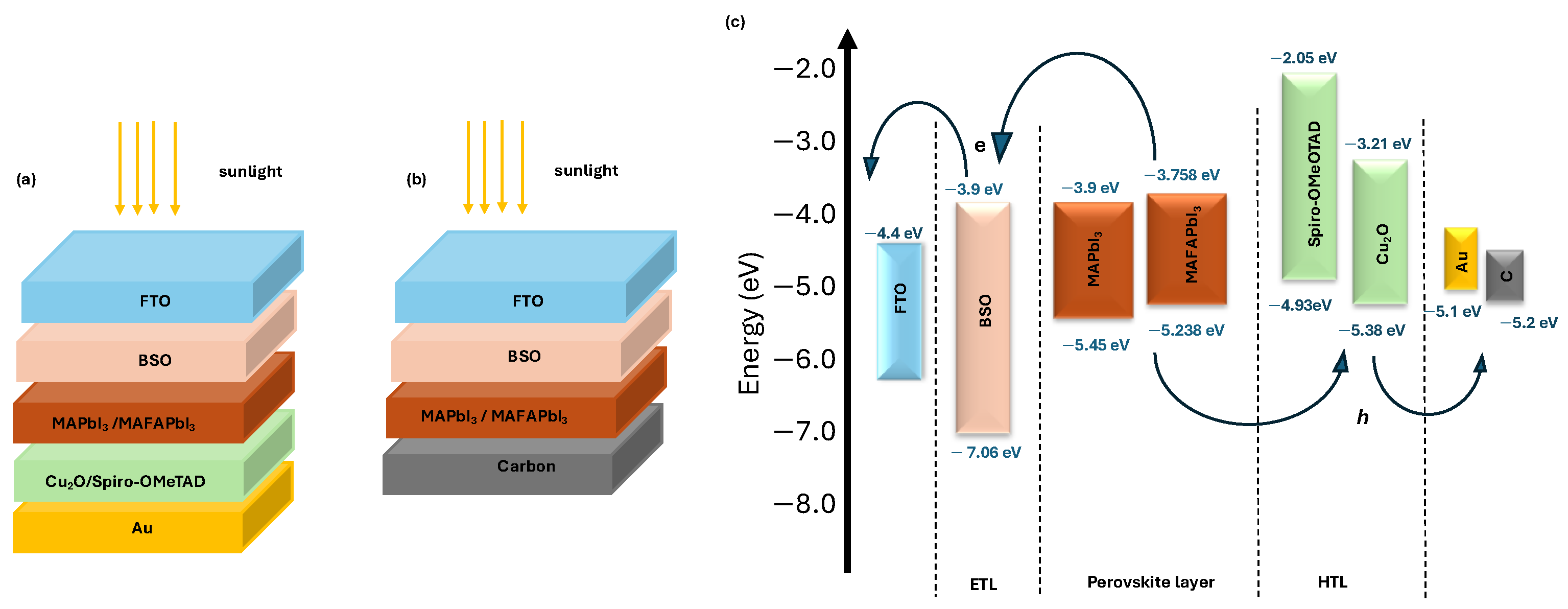
2. Methodologies
3. Results and Discussion
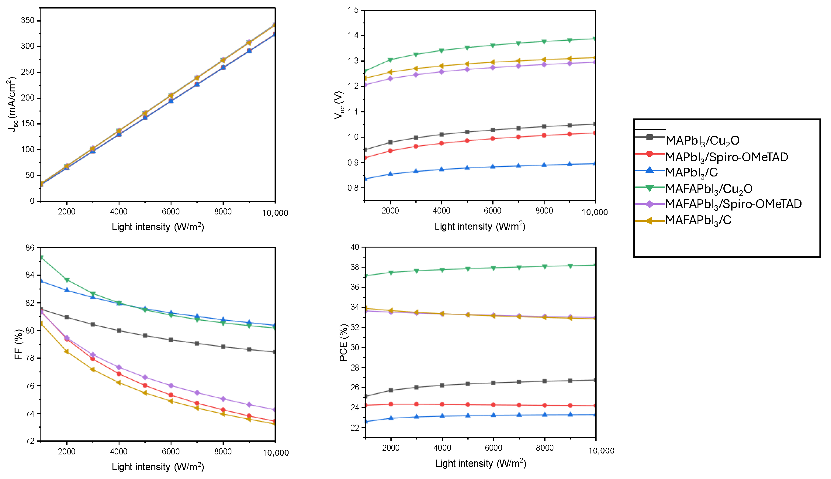
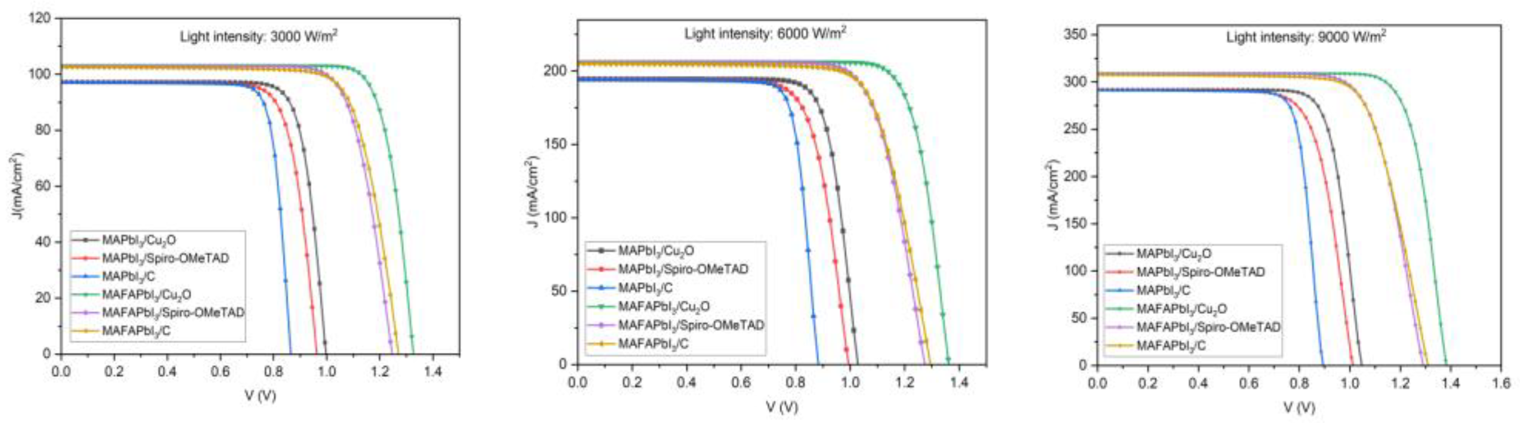
3.1. The Effect of Varying Light Intensity
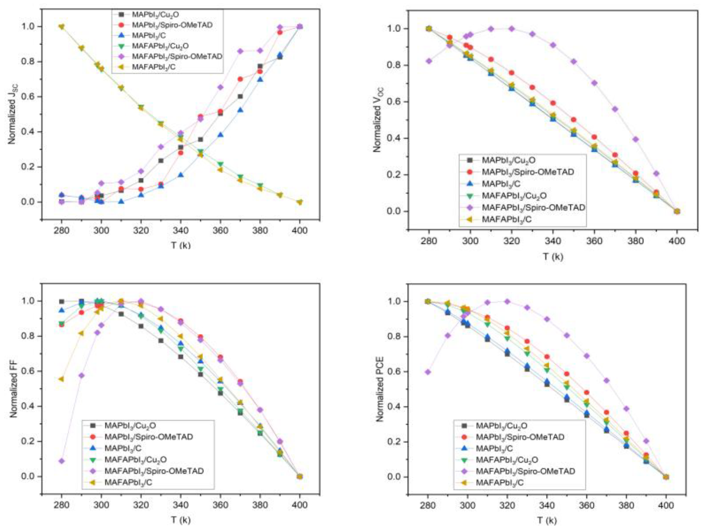
3.2. The Effect of Operation Temperature
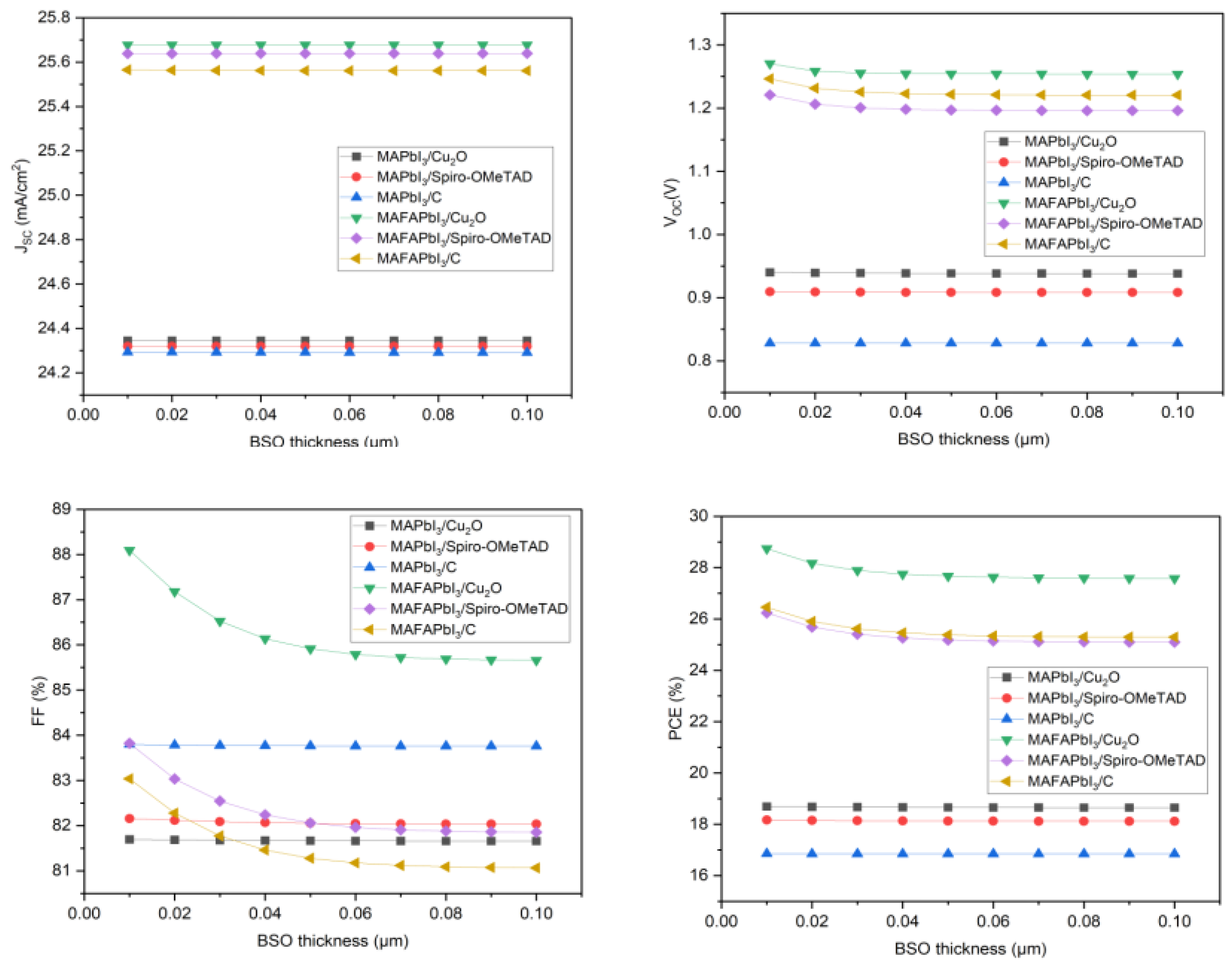
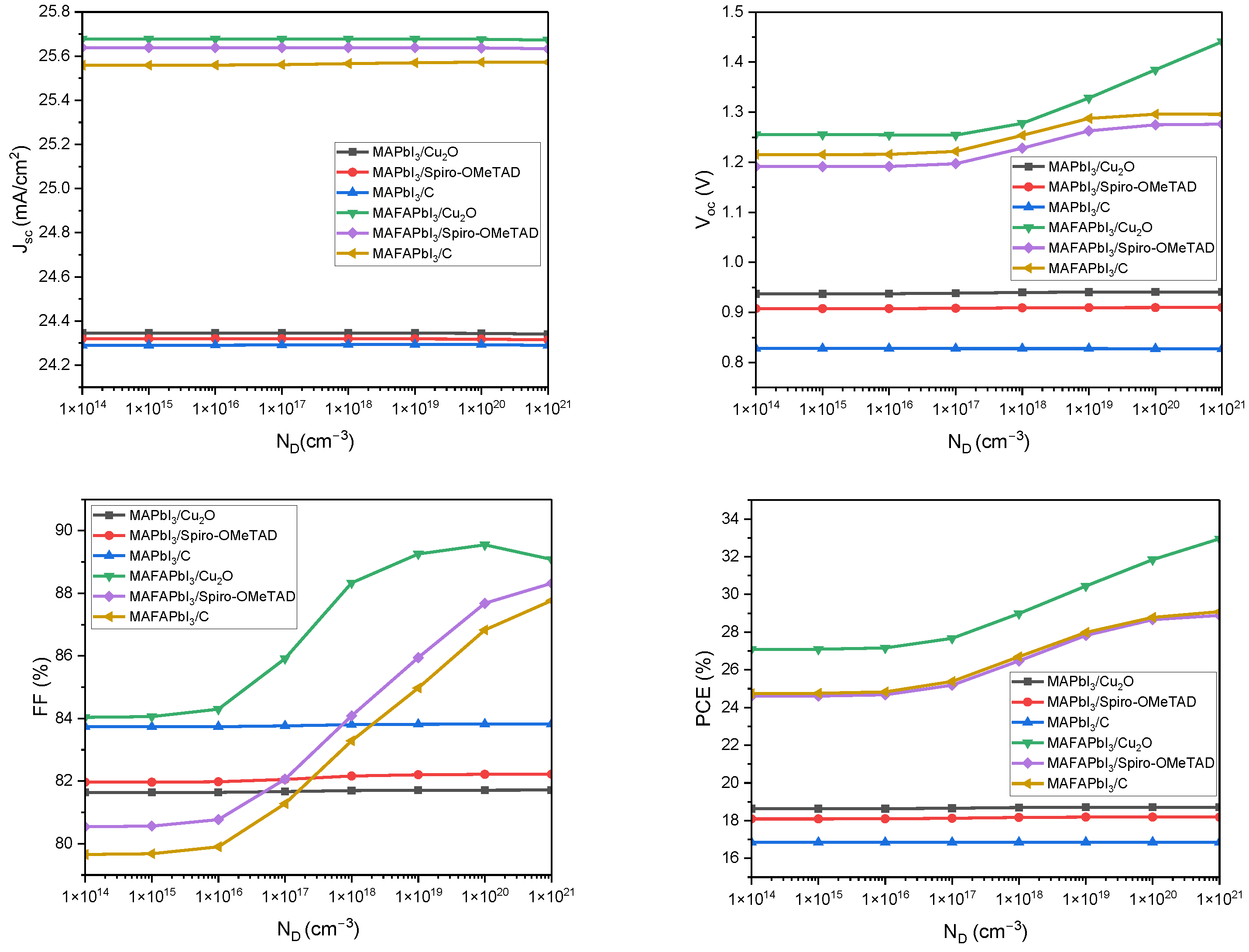
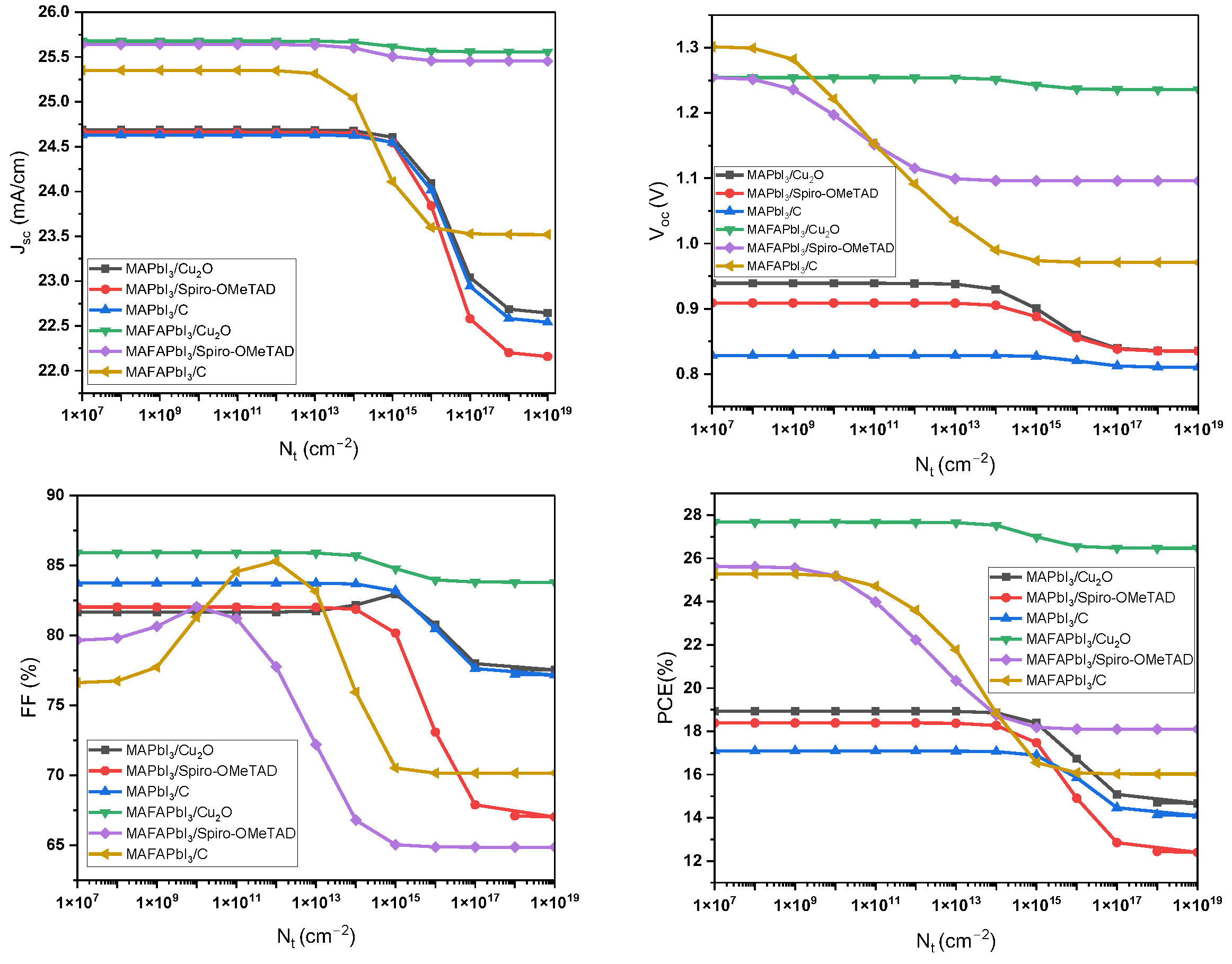
3.3. The Impact of BSO Thickness, Donor Density, and Defect Density
4. Conclusions and Future Work Suggestions
Author Contributions
Funding
Data Availability Statement
Acknowledgments
Conflicts of Interest
Abbreviations
| Abbreviation | Definition |
| PSCs | Perovskite solar cells |
| ETL | Electron transport layer |
| HTL | Hole transport layer |
| MAPbI3 | Methylammonium lead iodide |
| MAFAPbI3 | Methylammonium formamidinium lead iodide |
| ETMs | Electron transport materials |
| PCE | Power conversion efficiency |
| CPV | Concentrated photovoltaic |
| JSC | Short-circuit current density |
| VOC | Open-circuit voltage |
| FF | Fill factor |
| RS | Series resistance |
| BSO | BaSnO3 barium stannate oxide |
| CPSCs | Carbon-based perovskite solar cells |
| EQE | External quantum efficiency |
| CBO | Conduction band offset |
| VBO | Valence band offset |
| Temperature coefficient (CT) of the PCE of solar cells | |
| CT | Temperature coefficient |
| ηSTC | Efficiency at standard test conditions |
| ηT | Efficiency at temperature T |
| Ea | Activation energy for recombination |
| Eg | Energy bandgap |
| χ | Electron affinity |
| ND | Donor concentration density |
| Nt | Defect density |
| Ψ | Electrostatic potential |
| ϵ | Permittivity |
| R | Recombination rate |
| q | Charge of the electron |
| n | Concentration of free electrons |
| p | Concentration of free holes |
| NA | Acceptor concentration density |
| Jn | Electron density |
| Jp | Holes density |
| α | Recombination coefficient |
| Plight | Power of the incident light |
| k | Boltzmann constant |
| T | Absolute temperature |
| Saturation current | |
| Short-circuit current under light concentration | |
| Open-circuit voltage under light concentration | |
| Maximum power under light concentration | |
| Maximum current density | |
| Maximum voltage | |
| Fill factor without influence |
References
- Kojima, A.; Teshima, K.; Shirai, Y.; Miyasaka, T. Organometal halide perovskites as visible-light sensitizers for photovoltaic cells. J. Am. Chem. Soc. 2009, 131, 6050–6051. [Google Scholar] [CrossRef] [PubMed]
- Liu, Z.; Liu, T.; Yu, L.; He, T.; Liu, P.; Li, M.; Yuan, M. Efficient and Stable FA-Rich Perovskite Photovoltaics: From Material Properties to Device Optimization; John Wiley and Sons Inc.: Hoboken, NJ, USA, 2022. [Google Scholar] [CrossRef]
- Wang, R.; Huang, T.; Xue, J.; Tong, J.; Zhu, K.; Yang, Y. Prospects for Metal Halide Perovskite-Based Tandem Solar Cells. Nat. Photonics 2021, 15, 411–425. [Google Scholar] [CrossRef]
- Bhandari, S.; Roy, A.; Mallick, T.K.; Sundaram, S. Impact of different light induced effect on organic hole-transporting layer in perovskite solar cells. Mater. Lett. 2020, 268, 127568. [Google Scholar] [CrossRef]
- Bhandari, S.; Valsalakumar, S.; Chanchangi, Y.; Selvaraj, P.; Mallick, T.K. Effect of novel graphitic carbon/NiO hole transporting electrode on the photovoltaic and optical performance of semi-transparent perovskite solar cells. RSC Adv. 2023, 13, 7380–7384. [Google Scholar] [CrossRef]
- Bello, S.; Urwick, A.; Bastianini, F.; Nedoma, A.J.; Dunbar, A. An introduction to perovskites for solar cells and their characterisation. Energy Rep. 2022, 8, 89–106. [Google Scholar] [CrossRef]
- Tonui, P.; Oseni, S.O.; Sharma, G.; Yan, Q.; Mola, G.T. Perovskites Photovoltaic Solar Cells: An Overview of Current Status; Elsevier Ltd.: Amsterdam, The Netherlands, 2018. [Google Scholar] [CrossRef]
- Hussain, I.; Tran, H.P.; Jaksik, J.; Moore, J.; Islam, N.; Uddin, M.J. Functional materials, device architecture, and flexibility of perovskite solar cell. Emergent Mater. 2018, 1, 133–154. [Google Scholar] [CrossRef]
- Hui, W.; Zhang, B.; Wang, B.; Gu, L.; Bao, Y.; Kang, X.; Su, Z.; Li, D.; Huang, W.; Song, L.; et al. Stable Electron-Transport-Layer-Free Perovskite Solar Cells with over 22% Power Conversion Efficiency. Nano Lett. 2023, 23, 2195–2202. [Google Scholar] [CrossRef]
- Li, S.; Li, Y.; Sun, X.; Li, Y.; Deng, F.; Tao, X. Hole transport layer-free carbon-based perovskite solar cells with high-efficiency up to 17.49% in air: From-bottom-to-top perovskite interface modification. Chem. Eng. J. 2023, 455, 140727. [Google Scholar] [CrossRef]
- Lu, H.; Jiang, Y.; Zhong, J.; Zhao, R.; Liang, T.; Li, H.; Zhao, J.; Fang, S.; Ji, C.; Li, D.; et al. Fabricating an optimal rutile TiO2 electron transport layer by delicately tuning TiCl4 precursor solution for high performance perovskite solar cells. Nano Energy 2020, 68, 104336. [Google Scholar] [CrossRef]
- Myung, C.W.; Lee, G.; Kim, K.S. La-doped BaSnO3 electron transport layer for perovskite solar cells. J. Mater. Chem. A Mater. 2018, 6, 23071–23077. [Google Scholar] [CrossRef]
- Leijtens, T.; Eperon, G.E.; Pathak, S.; Abate, A.; Lee, M.M.; Snaith, H.J. Overcoming ultraviolet light instability of sensitized TiO2 with meso-superstructured organometal tri-halide perovskite solar cells. Nat. Commun. 2013, 4, 3885. [Google Scholar] [CrossRef] [PubMed]
- Raj, A.; Sharma, S.; Singh, K.; Laref, A.; Anshul, A.; Kumar, M.; Kumar, A. Effect of doping engineering in TiO2 electron transport layer on photovoltaic performance of perovskite solar cells. Mater. Lett. 2022, 313, 131692. [Google Scholar] [CrossRef]
- Wu, W.Q.; Chen, D.; Li, F.; Cheng, Y.B.; Caruso, R.A. Solution-processed Zn2SnO4 electron transporting layer for efficient planar perovskite solar cells. Mater. Today Energy 2018, 7, 260–266. [Google Scholar] [CrossRef]
- Kohan, M.; Mahmoudi, T.; Wang, Y.; Im, Y.H.; Hahn, Y.B. SnO2/BaSnO3 electron transport materials for stable and efficient perovskite solar cells. Appl. Surf. Sci. 2023, 613, 156068. [Google Scholar] [CrossRef]
- Guo, Q.; Dong, J.; Lin, J.; Huang, M.; Lan, Z.; Huang, Y.; Wei, Y.; Liu, X.; Yang, Y.; Jia, J.; et al. High-Performance and Hysteresis-Free Perovskite Solar Cells Based on Rare-Earth-Doped SnO2 Mesoporous Scaffold. Research 2019, 2019, 4049793. [Google Scholar] [CrossRef]
- Shin, S.S.; Park, J.H.; Kim, J.S.; Suk, J.H.; Lee, K.D.; Hong, K.S.; Kim, D.W.; Kim, J.Y.; Cho, I.S. Improved quantum efficiency of highly efficient perovskite BaSnO3-based dye-sensitized solar cells. ACS Nano 2013, 7, 1027–1035. [Google Scholar] [CrossRef]
- Shin, S.S.; Han, B.S.; Kim, J.S.; Hwang, D.; Oh, L.S.; Suk, J.H.; Kim, J.Y.; Kim, D.H.; Hong, K.S.; Kim, D.W. Controlled interfacial electron dynamics in highly efficient Zn2SnO4-based dye-sensitized solar cells. ChemSusChem 2014, 7, 501–509. [Google Scholar] [CrossRef]
- Sun, C.; Fang, B.; Yang, J.; Chen, Y.; Guan, L.; Liu, H.; Li, H.; Guo, Y.; Duan, H. Ternary oxide BaSnO3 nanoparticles as an efficient electron-transporting layer for planar perovskite solar cells. J. Alloys Compd. 2017, 722, 196–206. [Google Scholar] [CrossRef]
- Rahman, A. Design and Simulation of High-performance Planar npp+ Heterojunction CH3NH3PbI3 Based Perovskite Solar Cells Using BaSnO3 ETM and Cu2O HTM. Res. Sq. 2021. [Google Scholar] [CrossRef]
- Tara, A.; Bharti, V.; Dixit, H.; Sharma, S.; Gupta, R. Performance evaluation of all-inorganic cesium-based perovskite solar cell with BaSnO3 as ETL. J. Nanoparticle Res. 2023, 25, 9. [Google Scholar] [CrossRef]
- Shin, S.S.; Gao, Z.R.; Lin, Q.-F.; Liu, C.; Gao, F.; Lin, C.; Zhang, S.; Deng, H.; Mayoral, A.; Fan, W.; et al. Colloidally Prepared La-Doped BaSnO3 Electrodes for Efficient, Photostable Perovskite Solar Cells. 2017. Available online: https://www.science.org (accessed on 12 December 2024).
- Dileep, K.R.; Veerappan, G.; Rao, T.N.; Mallick, S.; Ashina, A.; Rajbhar, M.K.; Ramasamy, E. A facile co-precipitation method for synthesis of Zn doped BaSnO3 nanoparticles for photovoltaic application. Mater. Chem. Phys. 2021, 258, 123939. [Google Scholar] [CrossRef]
- Wang, Z.; Klug, M.T.; Wenger, B.; Herz, L.M.; Johnston, M.B.; Lin, Q.; Snaith, H.J.; Christoforo, M.G.; Lin, Y.-H.; Klug, M.T.; et al. High irradiance performance of metal halide perovskites for concentrator photovoltaics. Nat. Energy 2018, 3, 855–861. [Google Scholar] [CrossRef]
- Zhou, Y.; Gray-Weale, A. A numerical model for charge transport and energy conversion of perovskite solar cells. Phys. Chem. Chem. Phys. 2016, 18, 4476–4486. [Google Scholar] [CrossRef] [PubMed]
- Troughton, J.; Gasparini, N.; Baran, D. Cs0.15FA0.85PbI3 perovskite solar cells for concentrator photovoltaic applications. J. Mater. Chem. A Mater. 2018, 6, 21913–21917. [Google Scholar] [CrossRef]
- Sadhukhan, P.; Nazeeruddin, M.K.; Sengupta, P.; Sundaram, S.; Roy, A.; Das, S.; Mallick, T.K. The Emergence of Concentrator Photovoltaics for Perovskite Solar Cells. Appl. Phys. Rev. 2021, 8, 041324. [Google Scholar] [CrossRef]
- Baig, H.; Kanda, H.; Asiri, A.M.; Nazeeruddin, M.K.; Mallick, T. Increasing efficiency of perovskite solar cells using low concentrating photovoltaic systems. Sustain. Energy Fuels 2020, 4, 528–537. [Google Scholar] [CrossRef]
- Bach, U.; Spreitzer, H.; Lupo, D.; Comte, P.; Weissörtel, F.; Grätzel, M.; Salbeck, J.; Moser, J.E. Solid-State Dye-Sensitized Mesoporous TiO2 Solar Cells with High Photon-to-Electron Conversion Efficiencies. 1998. Available online: www.nature.com (accessed on 12 December 2024).
- Nguyen, W.H.; Bailie, C.D.; Unger, E.L.; McGehee, M.D. Enhancing the hole-conductivity of spiro-OMeTAD without oxygen or lithium salts by using spiro(TFSI)2 in perovskite and dye-sensitized solar cells. J. Am. Chem. Soc. 2014, 136, 10996–11001. [Google Scholar] [CrossRef]
- Bhandari, S.; Mallick, T.K.; Sundaram, S. Enlightening the temperature coefficient of triple mesoscopic CH3NH3PbI3−xClx/NiO and double mesoscopic CsFAMAPbI3−xBrx/CuSCN carbon perovskite solar cells. J. Phys. Energy 2023, 5, 2. [Google Scholar] [CrossRef]
- Christians, J.A.; Fung, R.C.M.; Kamat, P.V. An inorganic hole conductor for Organo-lead halide perovskite solar cells. improved hole conductivity with copper iodide. J. Am. Chem. Soc. 2014, 136, 758–764. [Google Scholar] [CrossRef]
- Ito, S.; Tanaka, S.; Vahlman, H.; Nishino, H.; Manabe, K.; Lund, P. Carbon-double-bond-free printed solar cells from TiO2/CH3NH3PbI3/CuSCN/Au: Structural control and photoaging effects. ChemPhysChem 2014, 15, 1194–1200. [Google Scholar] [CrossRef]
- Srivastava, V.; Chauhan, R.K.; Lohia, P. Highly efficient cesium-based halide perovskite solar cell using SCAPS-1D software: Theoretical study. J. Opt. 2023, 52, 1218–1225. [Google Scholar] [CrossRef]
- Son, C.; Son, H.; Jeong, B.S. Enhanced Conversion Efficiency in MAPbI3 Perovskite Solar Cells through Parameters Optimization via SCAPS-1D Simulation. Appl. Sci. 2024, 14, 2390. [Google Scholar] [CrossRef]
- Valsalakumar, S.; Bhandari, S.; Mallick, T.K.; Hinshelwood, J.; Sundaram, S. Experimental Validation of Optimized Solar Cell Capacitance Simulation for Rheology-Modulated Carbon-Based Hole Transport Layer-Free Perovskite Solar Cell. Adv. Energy Sustain. Res. 2024, 5, 244. [Google Scholar] [CrossRef]
- Abena, A.M.N.; Ngoupo, A.T.; Abega, F.X.A.; Ndjaka, J.M.B. Numerical investigation of solar cells based on hybrid organic cation perovskite with inorganic HTL via SCAPS-1D. Chin. J. Phys. 2022, 76, 94–109. [Google Scholar] [CrossRef]
- Tan, K.; Lin, P.; Wang, G.; Liu, Y.; Xu, Z.; Lin, Y. Controllable design of solid-state perovskite solar cells by SCAPS device simulation. Solid State Electron. 2016, 126, 75–80. [Google Scholar] [CrossRef]
- Hossain, M.I.; Alharbi, F.H.; Tabet, N. Copper oxide as inorganic hole transport material for lead halide perovskite based solar cells. Solar Energy 2015, 120, 370–380. [Google Scholar] [CrossRef]
- Abdelaziz, S.; Zekry, A.; Shaker, A.; Abouelatta, M. Investigating the performance of formamidinium tin-based perovskite solar cell by SCAPS device simulation. Opt. Mater. 2020, 101, 109738. [Google Scholar] [CrossRef]
- Abena, A.M.N.; Ngoupo, A.T.; Ndjaka, J.M.B. Computational analysis of mixed cation mixed halide-based perovskite solar cell using SCAPS-1D software. Heliyon 2022, 8, e11428. [Google Scholar] [CrossRef]
- Raza, E.; Ahmad, Z.; Riaz, K.; Aziz, F.; Bhadra, J.; Al-Thani, N.J.; Asif, M.; Ahmed, A. Numerical simulation analysis towards the effect of charge transport layers electrical properties on cesium based ternary cation perovskite solar cells performance. Solar Energy 2021, 225, 842–850. [Google Scholar] [CrossRef]
- Minemoto, T.; Murata, M. Theoretical analysis on effect of band offsets in perovskite solar cells. Sol. Energy Mater. Sol. Cells 2015, 133, 8–14. [Google Scholar] [CrossRef]
- Ahmed, A.; Riaz, K.; Mehmood, H.; Tauqeer, T.; Ahmad, Z. Performance optimization of CH3NH3Pb(I1-xBrx)3 based perovskite solar cells by comparing different ETL materials through conduction band offset engineering. Opt. Mater. 2020, 105, 109897. [Google Scholar] [CrossRef]
- Xu, L.; Imenabadi, R.M.; Vandenberghe, W.G.; Hsu, J.W.P. Minimizing performance degradation induced by interfacial recombination in perovskite solar cells through tailoring of the transport layer electronic properties. APL Mater. 2018, 6, 5021138. [Google Scholar] [CrossRef]
- Cheng, N.; Li, W.; Sun, S.; Zhao, Z.; Xiao, Z.; Sun, Z.; Zi, W.; Fang, L. A simulation study of valence band offset engineering at the perovskite/Cu2ZnSn(Se1-xSx)4 interface for enhanced performance. Mater. Sci. Semicond. Process. 2019, 90, 59–64. [Google Scholar] [CrossRef]
- Sharma, S.; Jain, K.K.; Sharma, A. Solar Cells: In Research and Applications—A Review. Mater. Sci. Appl. 2015, 6, 1145–1155. [Google Scholar] [CrossRef]
- El Himer, S.; Salvestrini, J.P.; El Himer, S.; Ahaitouf, A.; El Ayane, S. Photovoltaic Concentration: Research and Development. Energies 2020, 13, 5721. [Google Scholar] [CrossRef]
- Zerfaoui, H.; Dib, D.; Kadem, B. The Simulated Effects of Different Light Intensities on the SiC-Based Solar Cells. Silicon 2019, 11, 1917–1923. [Google Scholar] [CrossRef]
- Ahmed, S.; Jannat, F.; Khan, M.A.K.; Alim, M.A. Numerical development of eco-friendly Cs2TiBr6 based perovskite solar cell with all-inorganic charge transport materials via SCAPS-1D. Optik 2021, 225, 165765. [Google Scholar] [CrossRef]
- Dong, Z.; Zhu, L.; Liu, H.; Jiang, X.; Wang, H.; Li, W.; Chen, H. High-Temperature Perovskite Solar Cells. Solar RRL 2021, 5, 370. [Google Scholar] [CrossRef]
- Ghosh, B.K.; Hasanuzzman, M.; Saad, I.; Mohamad, K.A.; Hossain, M.K. Photovoltaic technologies photo-thermal challenges: Thin active layer solar cells significance. Optik 2023, 274, 170567. [Google Scholar] [CrossRef]
- Bhandari, S.; Roy, A.; Ghosh, A.; Mallick, T.K.; Sundaram, S. Perceiving the temperature coefficients of carbon-based perovskite solar cells. Sustain. Energy Fuels 2020, 4, 6283–6298. [Google Scholar] [CrossRef]
- Moot, T.; Parilla, P.A.; Johnston, S.W.; Morales, D.; Gould, I.E.; Wolf, E.J.; McAndrews, G.; Patel, J.B.; McGehee, M.D.; Luther, J.M.; et al. Temperature Coefficients of Perovskite Photovoltaics for Energy Yield Calculations. ACS Energy Lett. 2021, 6, 2038–2047. [Google Scholar] [CrossRef] [PubMed]
- Tress, W.; Carlsen, B.; Alharbi, E.A.; Agarwalla, A.; Graetzel, M.; Domanski, K.; Hagfeldt, A. Performance of perovskite solar cells under simulated temperature-illumination real-world operating conditions. Nat. Energy 2019, 4, 568–574. [Google Scholar] [CrossRef]
- Guo, Y.; Xue, Y.; Geng, C.; Li, C.; Li, X.; Niu, Y. Structural, Electronic, and Optical Characterizations of the Interface between CH3NH3PbI3 and BaSnO3 Perovskite: A First-Principles Study. J. Phys. Chem. C 2019, 123, 16075–16082. [Google Scholar] [CrossRef]
- Liang, C.; Xing, G. Doping Electron Transporting Layer: An Effective Method to Enhance JSC of All-Inorganic Perovskite Solar Cells. Energy Environ. Mater. 2021, 4, 500–501. [Google Scholar] [CrossRef]
- Alla, M.; Boubker, F.; Choudhary, E.; Bimli, S.; Rouchdi, M.; Samtham, M.; Kasaudhan, A.; Manjunath, V. Towards lead-free all-inorganic perovskite solar cell with theoretical efficiency approaching 23%. Mater. Technol. 2022, 37, 2963–2969. [Google Scholar] [CrossRef]
- Verma, U.K.; Singh, A. International Journal of Convergence in Healthcare Effect of Intensity on Perovskite Solar Cells Parameters by SCAPS-1D Simulation. Available online: www.ijcih.com (accessed on 20 December 2024).
- Li, H.; Huang, Y.; Zhu, M.; Yan, P.; Sheng, C. Analyzing Efficiency of Perovskite Solar Cells Under High Illumination Intensities by SCAPS Device Simulation. Nanomaterials 2025, 15, 286. [Google Scholar] [CrossRef]
- Shivesh, K.; Singh, S.V.; Kushwaha, A.K.; Kumar, M.; Alam, I. Investigating the theoretical performance of Cs2TiBr6-based perovskite solar cell with La-doped BaSnO3 and CuSbS2 as the charge transport layers. Int. J. Energy Res. 2021. [Google Scholar]
- Alghafis, A.; Sobayel, K. Performance evaluation of inorganic Cs3Bi2I9-based perovskite solar cells with BaSnO3 charge transport layer. Phys. Scr. 2024, 99, 7233. [Google Scholar] [CrossRef]


| Parameters | FTO [38] | BSO [22] | MAFAPbI3 [39] | MAPbI3 [36] | Cu2O [40] | Spiro-OMeTAD [41] |
|---|---|---|---|---|---|---|
| Thickness (nm) | 500 | 50 (vary) | 450 | 600 | 200 | 200 |
| Bandgap, Eg (eV) | 3.5 | 3.16 | 1.48 | 1.55 | 2.17 | 2.88 |
| Electron affinity, χ (eV) | 4 | 3.90 | 3.758 | 3.9 | 3.20 | 2.05 |
| Relative permittivity, ϵr | 9 | 17 | 6.5 | 32 | 7.11 | 3 |
| CB effective density of states, NC (cm−3) | 2.2 × 10¹⁷ | 1.2 × 10¹⁹ | 2.2 × 10¹⁵ | 2.8 × 10²⁰ | 2.02 × 10¹⁷ | 2.2 × 10¹⁸ |
| VB effective density of states, NV (cm−3) | 2.2 × 10¹⁶ | 1.8 × 10¹⁹ | 2.2 × 10¹⁷ | 3.9 × 10²⁰ | 1.1 × 10¹⁹ | 1.8 × 10¹⁹ |
| Electron mobility, μn (cm2/Vs) | 20 | 200 | 2 | 11.8 | 200 | 2.0 × 10⁻⁴ |
| Hole mobility, μp (cm2/Vs) | 10 | 25 | 2 | 11.8 | 80 | 2.0 × 10⁻⁴ |
| Donor density, ND (cm−3) | 1.0 × 10¹⁹ [22] | 1.0 × 10¹⁷ | 109 | 1.0 × 10¹³ | 0 | 0 |
| Acceptor density, NA (cm−3) | 0 | 0.0 | 109 | 1.0 × 10¹³ | 1 × 10¹⁸ | 2.0 × 10¹⁹ |
| Defect density, Nt (cm−3) | 1 × 10¹⁴ | 1.0 × 10¹⁵ | 1.0 × 10¹³ [42] | 3.0 × 10¹⁴ | 1.0 × 10¹⁵ [36] | 1.0 × 10¹⁵ |
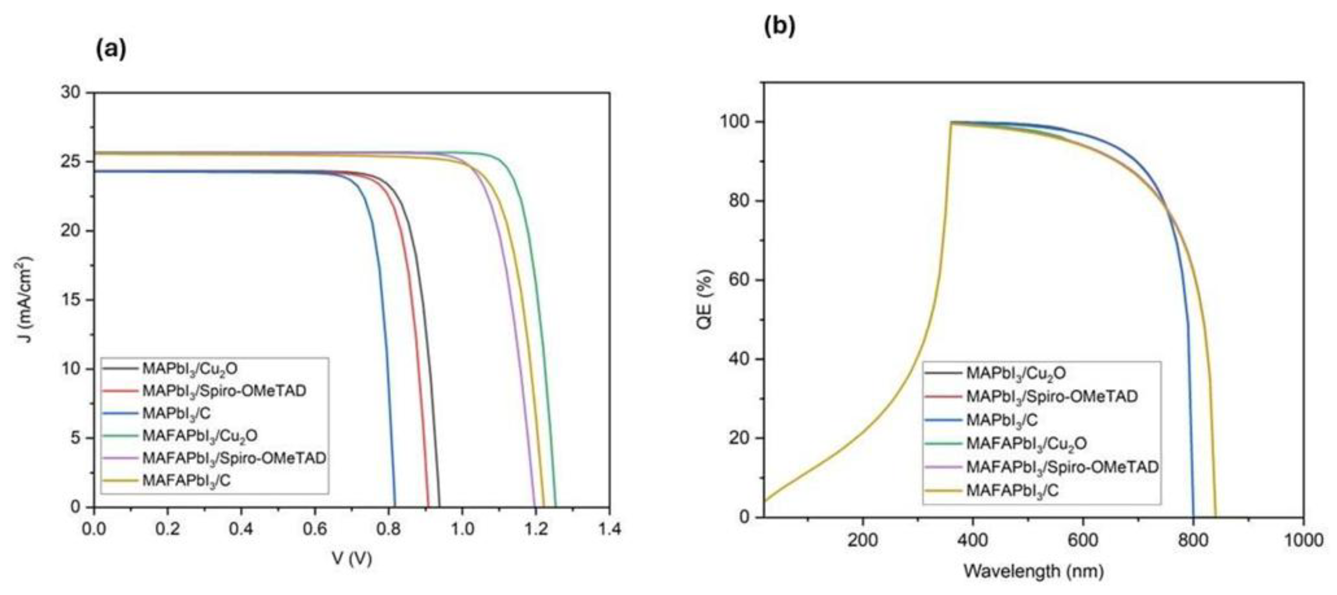
| Device Configuration | VOC (V) | JSC (mA/cm2) | FF (%) | PCE (%) |
|---|---|---|---|---|
| FTO/BSO/MAPbI3/Cu2O/Au | 0.938997 | 24.686179 | 81.6617 | 18.66 |
| FTO/BSO/MAPbI3/Spiro-OMeTAD/Au | 0.908349 | 24.319527 | 82.055 | 18.1264 |
| FTO/BSO/MAPbI3/C | 0.827971 | 24.2917242 | 83.7692 | 16.8484 |
| FTO/BSO/MAFAPbI3/Cu2O/Au | 1.25416 | 25.677727 | 85.9141 | 27.6678 |
| FTO/BSO/MAFAPbI3/Spiro-OMeTAD/Au | 1.19698 | 25.63886 | 82.0617 | 25.184 |
| FTO/BSO/MAFAPbI3/C | 1.221696 | 25.561464 | 81.2788 | 25.382 |
| Solar Cells | TCPCE (%)/Temperature Unit | Ref. |
|---|---|---|
| c-Si-based module | −0.45 | [53] |
| a-Si-based module | −0.13 | [53] |
| CdTe-based module | −0.21 | [53] |
| CIGS-based module | −0.36 | [53] |
| Organic | +0.4 | [52] |
| DSSC | −0.79 | [52] |
| TiO2/CsPbI2Br C-PSC | −0.23/°C at 200 °C, in reverse measurement | [52] |
| TiO2/CsPbI2Br C-PSC | C, in forward measurement | [52] |
| BSO/MAPbI3/Cu2O, | −0.112 at 400 K, simulation | [21] |
| BSO/MAPbI3/Cu2O | −0.341 at 400 K, simulation | This work |
| BSO/MAPbI3/Spiro-OMeTAD | −0.277 at 400 K, simulation | This work |
| BSO/MAPbI3/C | −0.292 at 400 K, simulation | This work |
| BSO/MAFAPbI3/Cu2O | −0.078 at 400 K, simulation | This work |
| BSO/MAFAPbI3/Spiro-OMeTAD | +0.0285 at 320 K, −0.04 at 400 K, simulation | This work |
| BSO/MAFAPbI3/C | −0.066 at 400 K, simulation | This work |
| TiO2/m-Al2O3/MAPbI3/C | +2.5 × 10⁻² (5 °C ≤ T ≤ 25 °C) and −1.8 × 10⁻² (25 °C ≤ T ≤ 75 °C) | [54] |
| PTAA/FA0.75Cs0.22MA0.03Pb(I0.82Br0.15Cl0.03)3 | −0.11 at 80 °C | [55] |
| NiOx/FA0.79MA0.16Cs0.05Pb (I0.83,Br0.17)3 | −0.08 at 80 °C | [55] |
| TiO2/FAMACsPb(I,Br)3/Spiro-OMeTAD /Au | A single is not found at 50 °C | [56] |
| Parameters | Result | References |
|---|---|---|
| Light intensity | 19.02% PCE (at 1000 Wm−2) | [60] |
| 38% PCE (at 10,000 Wm−2) | This work | |
| 21% PCE (at 1000 Wm−2) | [61] | |
| 32.04% PCE (at 1000 Wm−2) | [21] | |
| BSO thickness | 22.21% PCE (at 10 nm) | [22] |
| ~27% PCE (at 30 nm) | [59] | |
| 31.24% PCE (at 100 nm) | [21] | |
| 29% PCE (at 10 nm) | This work | |
| BSO donor concentration | 29.13% PCE (at 1021 cm−3) | [62] |
| 33% PCE (at 1021 cm−3) | This work | |
| 31.24% PCE (at >1020 cm−3) | [21] | |
| ~28% PCE (at 1020 cm−3) | [59] | |
| BSO/perovskite interface defect density | 18.59% PCE (at 1015 cm−2) | [60] |
| 27.6% PCE (at 1014 cm−2) | This work | |
| 22.10% PCE (at 1014 cm−2) | [22] | |
| 20.9% PCE (at 1010 cm−2) | [63] |
Disclaimer/Publisher’s Note: The statements, opinions and data contained in all publications are solely those of the individual author(s) and contributor(s) and not of MDPI and/or the editor(s). MDPI and/or the editor(s) disclaim responsibility for any injury to people or property resulting from any ideas, methods, instructions or products referred to in the content. |
© 2025 by the authors. Licensee MDPI, Basel, Switzerland. This article is an open access article distributed under the terms and conditions of the Creative Commons Attribution (CC BY) license (https://creativecommons.org/licenses/by/4.0/).
Share and Cite
Alkathran, N.; Bhandari, S.; Mallick, T.K. Theoretical Performance of BaSnO3-Based Perovskite Solar Cell Designs Under Variable Light Intensities, Temperatures, and Donor and Defect Densities. Designs 2025, 9, 76. https://doi.org/10.3390/designs9030076
Alkathran N, Bhandari S, Mallick TK. Theoretical Performance of BaSnO3-Based Perovskite Solar Cell Designs Under Variable Light Intensities, Temperatures, and Donor and Defect Densities. Designs. 2025; 9(3):76. https://doi.org/10.3390/designs9030076
Chicago/Turabian StyleAlkathran, Nouf, Shubhranshu Bhandari, and Tapas K. Mallick. 2025. "Theoretical Performance of BaSnO3-Based Perovskite Solar Cell Designs Under Variable Light Intensities, Temperatures, and Donor and Defect Densities" Designs 9, no. 3: 76. https://doi.org/10.3390/designs9030076
APA StyleAlkathran, N., Bhandari, S., & Mallick, T. K. (2025). Theoretical Performance of BaSnO3-Based Perovskite Solar Cell Designs Under Variable Light Intensities, Temperatures, and Donor and Defect Densities. Designs, 9(3), 76. https://doi.org/10.3390/designs9030076