1. Introduction
Mechatronic systems originate from the synergetic integration of mechanical, electrical, and software engineering [
1]. Their complexity increases markedly, as they cannot be efficiently developed by a single technical sphere. A variety of trends are driving the growth of mechatronic systems including reduced innovation cycles and time-to-market through simultaneous engineering, improved product functionality thanks to enhanced information processing efficiency, and a growing product diversity driven by global competition and customized product configurations [
2]. The confluence of such systems with information technology and embedded systems leads to the idea of cyber–physical systems within the perspective of Industry 4.0 [
3].
As the quest for greener products is increasingly intensifying, new challenges are arising, making mechatronic systems more complex, particularly when it comes to their sustainable design. Indeed, sustainability requirements are prompted by public and political awareness of the accelerating pace of climate change, the increasing water pollution, and the disposal of waste, together with the fast consumption of natural resources. Sustainable design is a framework intended to incorporate environmental objectives throughout the design and development of a product, aimed at reducing its negative impact on the environment across the entire life cycle, and, therefore, encourage organizations to improve their environmental performance constantly [
4]. Within this perspective, the mechatronics industry and, particularly, mechatronics designers are faced with environmental requirements, legislative regulations, and environmentally conscious customers. They need to be equipped with tools to identify, evaluate, and prevent the environmental impact of the whole mechatronic system and its manufacturing from the initial design stages.
Against this background, various initiatives and studies have been launched to assist companies in their mechatronic systems ’eco-design. For instance, Germani et al. [
5] presented a new tool for supporting mechatronic product design, applying the usual eco-design guidelines combined with designers’ previous experiences. It has been established using the case-based reasoning methodology. Luttrop et al. [
6] outlined ten golden rules for mechatronic systems eco-design, notably, do not use toxic substances, minimize resources and energy consumption, promote repair and upgrade, minimize weight, and consider investing in higher-quality materials. Buzuku et al. [
7] studied the major barriers associated with the implementation of the eco-design approach in an industrial context and proposed the use of the design structure matrix to solve the challenges encountered. The goal was to both identify and analyze the critical barriers and their interactions in conjunction with strategic environmental objectives. Sun et al. [
8] advanced a sustainable adaptive design methodology to address constantly changing environmental requirements, aiming at reducing resources consumption and waste in different life cycle periods. It starts with a classification of product requirements to identify customer perceptions proactively and then assesses the suitability of the available design to accommodate updated requirements by mapping functions to needs. Instead of focusing on general requirements, analytical calculations have been provided by Manuguerra et al. [
9] to support the eco-design of electric vehicles. The authors developed a software tool embedding life cycle assessment (LCA) throughout the design phase. The tool includes a database with both environmental and vehicle data, as well as a user interface for input and output, data processing, and environmental analysis. Reimer et al. [
10] examined the design of automotive body parts from a life cycle perspective, evaluating their mechanical performance and greenhouse gas emissions. The approach is structured around two key areas: LCA and analytical design. Along with environmental impacts’ considerations for mechatronic products, modularity and other structural elements also play a significant role in promoting eco-design. Favi et al. [
11] developed an approach and a software tool to quantify the disassembly and recyclability of mechatronic systems at the end-of-life phase. It starts with an analytical assessment in terms of time and cost to disassemble a given component, including antecedents, links, and properties. To define the end-of-life behavior, the authors chose the recyclability ratio proposed by the European Commission’s Joint Research Centre [
12]. One of the key eco-design considerations at the end of a product’s life is to guarantee that, regardless of the disposal method followed, the materials present in the final product will not have any hazardous effects. For instance, the accumulation of composite residues is currently becoming an environmental barrier in the mechatronics industry [
13]. One such composite is carbon fiber-reinforced polymer. Borges et al. [
14] worked on improving this composite, when it reached the end of its useful life, by incorporating its waste into a thermoplastic matrix to reproduce new components for the aerospace industry. Extending the lifetime of components and reusing them at the end of their useful life is a core driver towards green design. Wakiru et al. [
15] developed an integrated methodology for optimizing maintenance, remanufacturing, and numerous spare strategies to extend the lifetime of an aging multi-component mechatronic system with dependencies. A re-manufacturability indicator comprising factors such as replacement, reuse, repair, and clean reconditioning has been defined.
Minimizing the quantity, the size, and the weight of materials is a vital factor in eco-design projects. Even if it raises recycling constraints as already mentioned, in recent years, the use of carbon fiber-reinforced polymer composites, in mechatronic applications, has expanded, as they are lighter than steel and aluminum and five times stronger, which is particularly important for mechatronic systems embedded in automotive and aeronautics industries [
16]. Toyota Industries designed its bipolar nickel–hydrogen battery so that the cathode is attached to one side of a metal component called a current collector and the anode is attached to the other side. These structures are piled on top of each other to build the battery. Thanks to this strategy, the number of parts is minimized, leading to a much smaller battery [
17].
The eco-design studies presented cover the assessment and the reduction of the product’s impact using LCA for specific mechatronic systems [
9,
10]. They explore the way the mechatronic system can be reconsidered at the end of its life through the design for disassembly [
11], the reuse at the end of life [
14], and the verification of the potential of its remanufacturing [
15]. Choosing reduced-impact materials [
16] and minimizing the size [
17] represent also an eco-design choice. The research belongs to three main eco-design pillars, the first comprises global guidelines [
5,
6,
7,
8], the second uses analytical tools [
9,
10], and the last focuses on a specific aspect or a particular life cycle phase [
11,
12,
13,
14,
15,
16,
17]. The guidelines assist the designers to set the global orientations of the project, but they remain notably without quantifiable results. However, the use of an exhaustive LCA requires considerable time, data, and human resources. It must also be conducted under rigorous conditions and be subjected to critical review to prevent overly hazardous analyses. However, it is important to examine the design guidelines against the analysis tools afterwards to ensure that they are mutually beneficial.
Mechatronic products’ complexity, resource or data limitations, and the objectives or deadlines of a study may lead an LCA analyst to simplify certain aspects of the design process [
18]. In LCA circles, the notion of simplification is traditionally associated with the quest for an easier and a faster evaluation [
19], driven by concerns that LCA is too sophisticated to be routinely implemented [
20]. We have presented an SLCA of a mechatronic system in [
21]. We have already advanced a four-step eco-design methodology [
22,
23] applicable to mechatronic systems characterized by a structural design freeze and having a restricted number of possible solutions (four admissible mechatronic solutions). We were able to select the candidate ecological solution, during the methodology’s last step, from the four possible ones by constructing manually what we call Design Environmental Matrices (DEMs) and calculating their related indicators. After mutual comparisons between DEMs, the admissible solution offering the lowest DEM indicator was selected as the ecological one. However, when the number of admissible solutions is relatively high, which is the case of mechatronic solutions in an industrial context, manual construction of DEMs and their mutual comparison are time-consuming and impractical; hence, there is a need to generalize the fourth step of the proposed methodology, where environmental considerations arise, to be relevant to any given set of admissible mechatronics solutions (including larger ones).
Colored Petri nets provide a formal tool (semantic and mathematical) together with a good graphical representation for modeling and analyzing discrete systems, particularly concurrent and parallel ones, which is the case of mechatronic systems. We can easily understand the modeled system, thanks to its graphical presentation and the existing natural relationship between the model and its physical properties [
24,
25]. They are deployed in a wide range of mechatronics applications like dependability assessment [
26], activity modelling [
27], and resources scheduling [
28]. We used previously CPN to build physical models deduced from SysML (System Modeling Language) [
29] models of both components and links constituting a mechatronic system [
22,
23]. We employed them as well to assess the reliability, the availability, and the maintainability of such systems [
30].
CPN enables us to overcome the above-mentioned issues, resulting from the manual construction of DEMs in the case of a large set of possible admissible solutions. Thus, the candidate ecological solution and its DEM could be reached via a quick simulation. Furthermore, in the light of building a global compact CPN model that addresses several structural and behavioral stochastic and deterministic problems of mechatronic systems, we have opted for the CPN to generalize the proposed mechatronic eco-design methodology advanced in [
22].
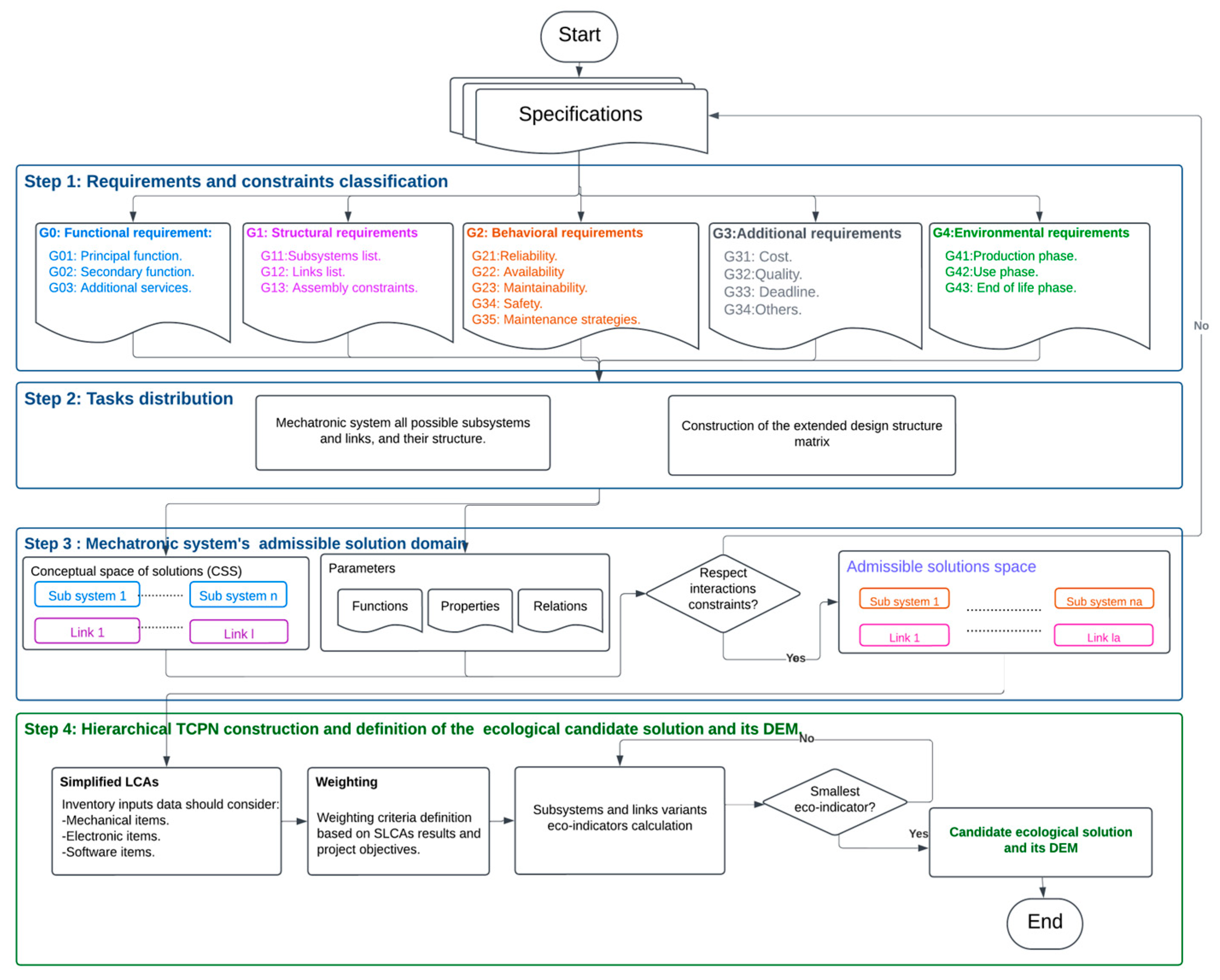
Within the scope of the present work, a generalization of the fourth step of the eco-design approach focusing on the environmental assessment of mechatronic systems with external structural design freeze offering a limited set of admissible solutions presented in [
22] will be developed. The overall methodology’s sequence is shown in
Figure 1. The three first steps were already advanced in [
22] and will not be addressed. We will focus on the fourth step, where environmental considerations manifest, which includes the realization of the SLCAs for all admissible solutions, weighting their results and selecting the candidate ecological solution and the construction of its DEM. From this perspective, we will introduce first the Hierarchical TCPN. Next, we will deploy it to consider the SLCAs’ results of all the admissible solutions, to implement the weighting process, and to obtain the candidate ecological solution among a large set of admissible ones. Then, we will illustrate the approach by taking the example of an RBS in its production phase using CPN Tools and OpenLCA software. Lastly, we will discuss the advantages and shortcomings of this work, and we will draw conclusions and perspectives.
2. Materials and Methods
As depicted in
Figure 1, the global sustainable conceptual design methodology is structured around four steps, the first three allow the definition of the admissible solutions domain (ASD) [
22]. The final step, which is the purpose of the current paper, involves the deployment of hierarchical TCPN including the SLCAs’ results for each admissible mechatronic system, the weighting of SLCAs’ results, and the definition of the candidate ecological solution and its DEM among a large set of admissible solutions. The work presented in [
22] is a special case of the current methodology, where the number of admissible solutions was restricted.
Mechatronic products are considered as subsystems interlinked via links. Subsystems may refer to a whole assembly or a single component. The current methodology is applied on mechatronic systems with external conceptual design freeze touching structural requirements [
31]; in this case, the number of subsystems and links’ families is the same for each admissible solution, but the solutions could be different in terms of the technologies used, the raw materials employed, the provider’s location, etc.
In the following, we will first introduce the hierarchical TCPN, and then, we will focus on its deployment in the last step of the sustainable conceptual design methodology (step 4 of
Figure 1) involving the selection of the candidate ecological solution from any size of admissible solutions (including larger ones).
2.1. Hierarchical Timed Colored Petri Nets (Hierarchical TCPN)
Colored Petri Net is a high-level Petri net for modeling discrete-event systems. It fuses the capabilities of a high-level programming language, CPN ML (Colored Petri Net Meta Language), based on SML (Standard Meta Language), with the power of Petri nets [
32]:
The formal definition of TCPN is advanced in [
23].
We outline hereafter the concepts of modularity and hierarchy [
33]:
A modular TCPN allows a TCPN to be turned into a system of inputs and outputs. In this fashion, the TCPN will behave like a black box named substitution transition with inputs and outputs in the form of places. When the places play the role of input or output, they act as input and/or output ports.
A modular TCPN is defined as a quadruple with the following:
TCPN is a timed colored Petri net.
a set of substitution transitions.
a set of port places.
a port type function assigning a port type to each port place.
Hierarchical TCPN allows modular manipulation of TCPN. A hierarchical TCPN is a set of modular TCPNs. Therefore, a hierarchical TCPN is a quadruple , where
S is a set of modules, and every module is a modular TCPN.
is a submodule function assigning a submodule to each substitution transition.
PS is a port socket relation function.
FS is a set of non-empty fusion sets, i.e., a set of places and transitions that if something applies to one place/transition it will be the same for all other places/transitions within the TCPN. Places/transitions within the fusion set are technically identical.
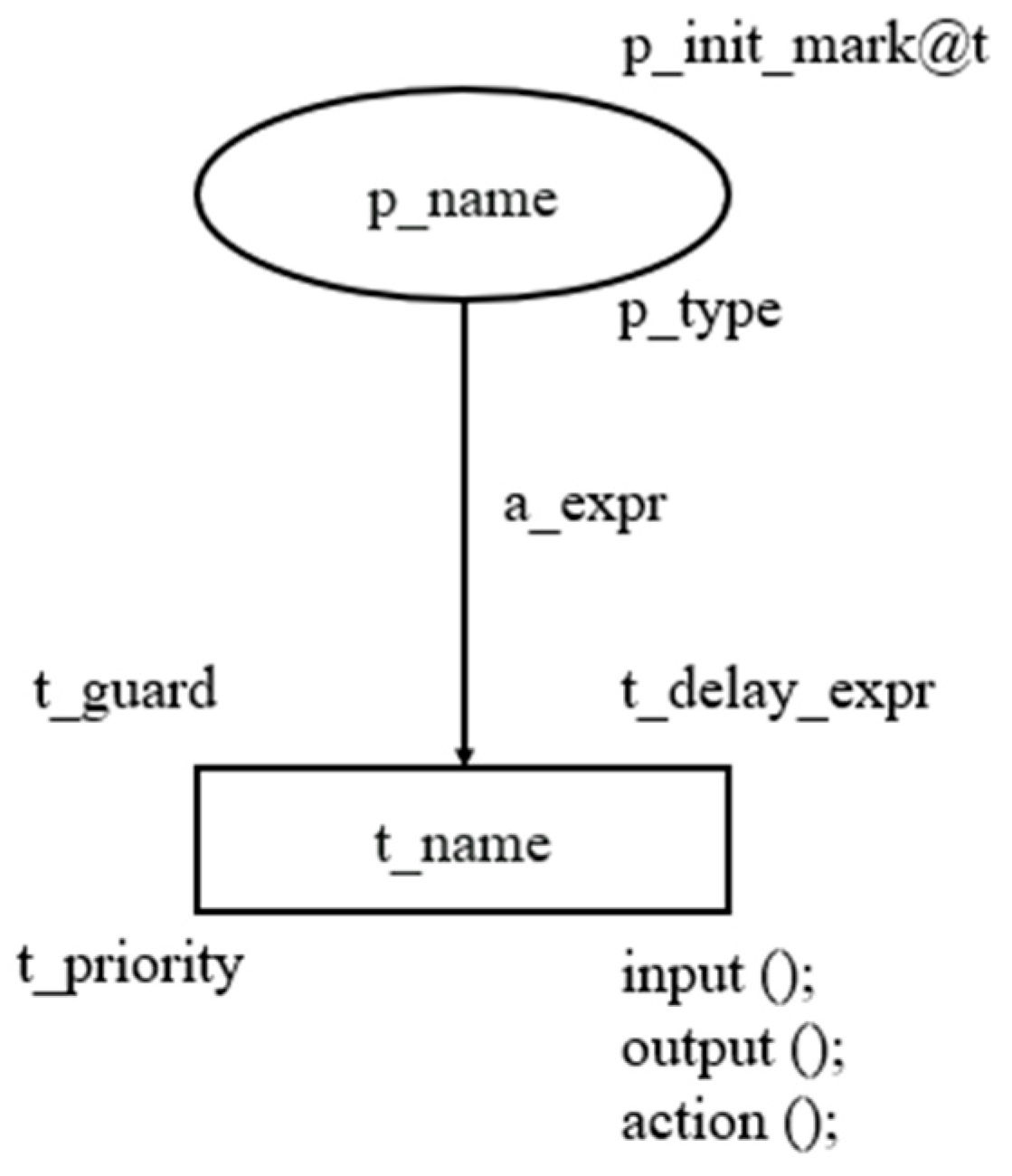
Figure 2 shows the graphical representation of the Hierarchical TCPN using CPN Tools software:
Substitution transitions are marked by a double line instead of one line for normal transitions.
2.2. Selection of the Candidate Ecological Solution Using Hierarchical TCPN
The ASD contains several item families of mechanical, electronic, and software types. The number of possible subsystems’ solutions
is given by Equation (1):
where
is the product of cardinalities of possible solutions (the number of variants) associated with the mechanical subsystem mi, and m is the number of mechanical subsystems’ families.
is the product of cardinalities of possible solutions (the number of variants) associated with the electronic subsystem ei, and e is the number of electronic subsystems’ families.
is the product of cardinalities of possible solutions (the number of variants) associated with the software subsystem si, and s is the number of electronic subsystems’ families.
Similarly, the number of possible links’ solutions
is expressed using Equation (2):
where
Given that the mechatronic system has a frozen design structure, its admissible solutions
are obtained by Equation (3):
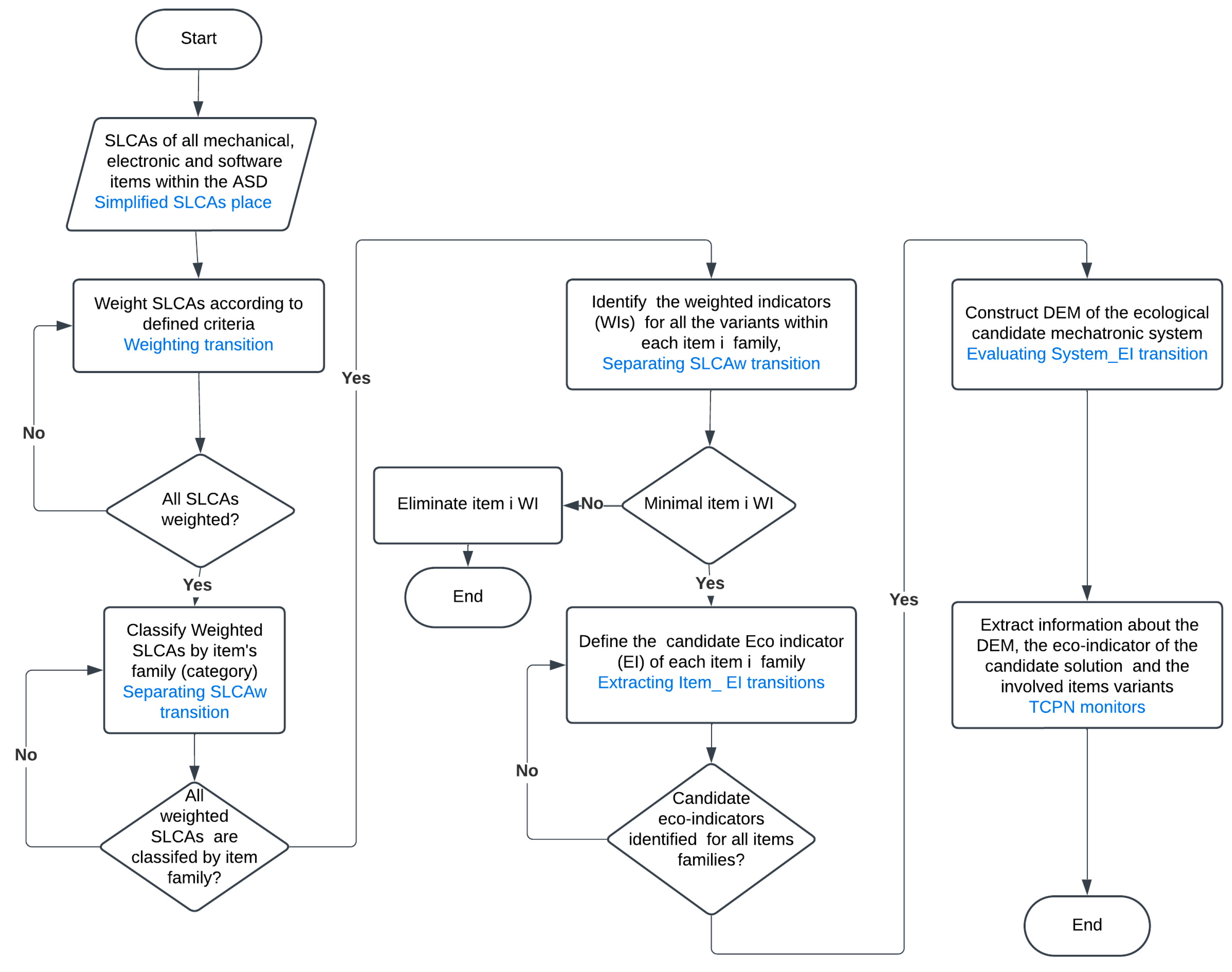
Hereafter, Item is used to designate a subsystem or a link constituting a mechatronic system. Each item family includes different variants; they are expressed as an integer. The flowchart of the Hierarchical TCPN model leading to the conclusion of the candidate ecological solution from a large set of admissible ones is presented in
Figure 3; the Hierarchical TCPN place/transition employed is specified in blue color.
2.2.1. Integration of SLCAs’ Results into the Hierarchical TCPN
Due to complete data availability and time constraints inherent to the industrial context, we choose SLCAs to assess the mechatronic systems. As a first step, we conduct a SLCA for each item within the ASD. The choice of SLCA software and the Life Cycle Impact Assessment method (LCIA) could be specified by the interested parties or by the project team via internal requirements. The same LCIA method should be unified throughout the project. LCIAs encompass several and heterogenous impact categories possessing different units as is the case of CML Baseline LCIA [
21,
22] of OpenLCA software [
34].
Although they are commonly perceived as immaterial, software items have an environmental impact. In fact, electricity and energy consumption is driven by their architecture and their deployment once embedded in a hardware item. In addition, software items can generate waste due to their obsolescence, which can result in hardware obsolescence where devices are discarded due to incompatibilities; their frequent updates, patches, or new versions requiring additional hardware resources; their end of life, as the software items are no longer supported or maintained [
35].
Therefore, we need to consider and incorporate SLCA inventory input data related to software items together with the inventory input data of their related hardware item.
Let us consider an LCIA method containing
n impact categories:
Impact 1…. Impact n. The SLCA results of an Item will be expressed by the color set
ItemLCA, so that:
| colset ItemLCA = record ItemName: ItemLCAName *
Impact_1: INT * … * | |
| Impact_n*Variant:INT; | |
It comprises data about:
The item’s family name ItemName.
The different impact categories: Impact_1…Impact_n.
The variant of the item within the ASD expressed as an integer: Variant.
We notice that an element of the set
ItemLCA is an (
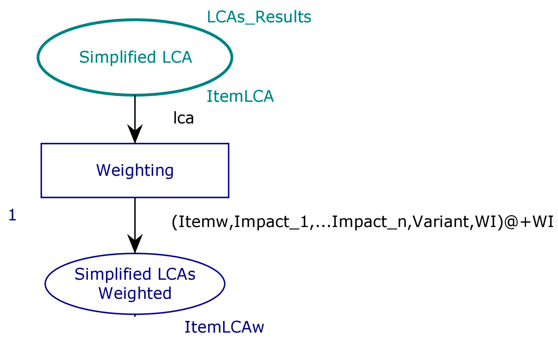
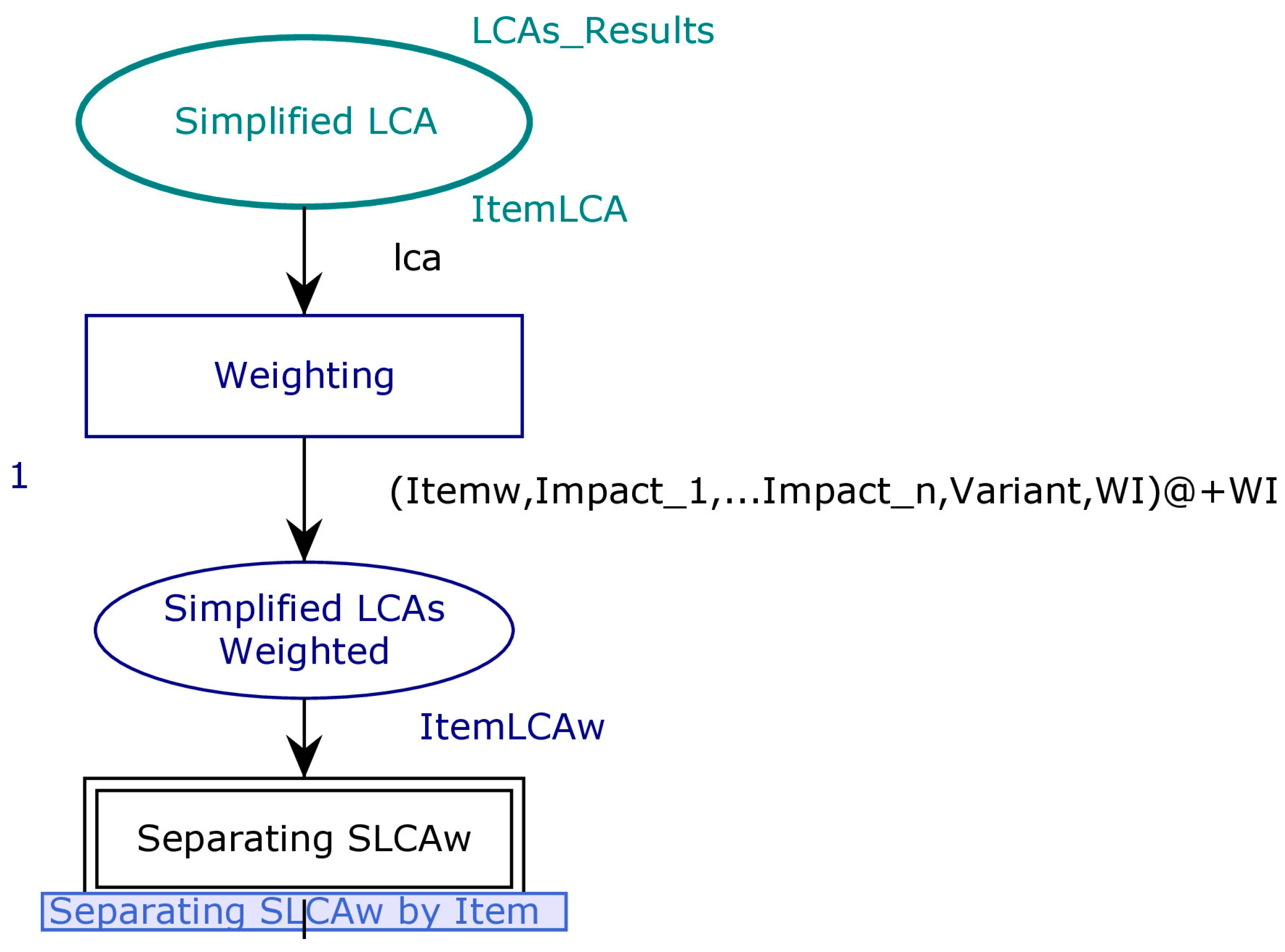
n + 2)-uplet, where n is the number of impact categories for the chosen LCIA. In
Figure 4, the token
LCAs_Results of type
ItemLCA contains all SLCAs’ results of the items belonging to the ASD.
2.2.2. Weighting Process Using Hierarchical CPN
This step consists of weighing the SLCAs results according to weighting criteria with threshold intervals defined by the project team. The idea behind the weighting process is to be able to compare and classify the various heterogeneous impact categories results of a specific LCIA since they have distinct characteristics and units.
The weighting process is as follows:
We gather the SLCAs’ results of all items variants within the ASD.
We set the environmental reduction rate and targets. These objectives could be specified by the customer or via internal recommendations. For example, we can apply a percentage reduction of the overall environmental impact of the mechatronic system or eliminate a specific impact category by selecting only items without this impact category, or others.
Based on the targets defined, we specify ranges for each impact category, deciding when the impact will be judged as high, medium, or low, then assigning it a weight (2 = low, 4 = medium, 6 = high).
We calculate the weighted indicator of each through Equation (4):
where
is the weight assigned to the impact category number
k for the
To model the weighting operation, the
Weighting transition of
Figure 4 is defined. The input of this transition contains the different SLCAs’ results of type
ItemLCA.
The output is expressed by the color set
ItemLCAw:
| closet ItemLCAw = record ItemName: ItemLCAName* Impact_1w: INT *… * | |
| Impact_nw:INT * Variant: INT * WI:INT timed; | |
It contains the following:
The item’s family name: ItemName;
Its different weighted impact categories of Equation (4), we denote them: Impact_1w…Impact_nw;
Its variant: Variant;
The weighted indicator noted WI, representing of Equation (4).
Within this transition, we define a transfer function to weight the different impact categories of the SLCAs according to the agreed weighting specifications.
We grant high priority to the transition
Weighting (priority equal to 1 in
Figure 4), to ensure that all the SLCAs are weighted first before processing to the next step. If not, we will face a concurrency [
36] where next transitions for already weighted items could be enabled before weighting the SLCAs’ results of all the possible items.
We store the value of the item weighted indicator WI in the time attribute using @+WI. We will explain later the reason for utilizing this time.
The place
Simplified LCAs weighted of
Figure 4 is defined to store all the weighting results for the different items.
Next, we need to isolate these results by item family to enable comparisons between the weighted indicators. For this reason, we define the transition
Separating SLCAw, which is the substitution transition of
Figure 5:
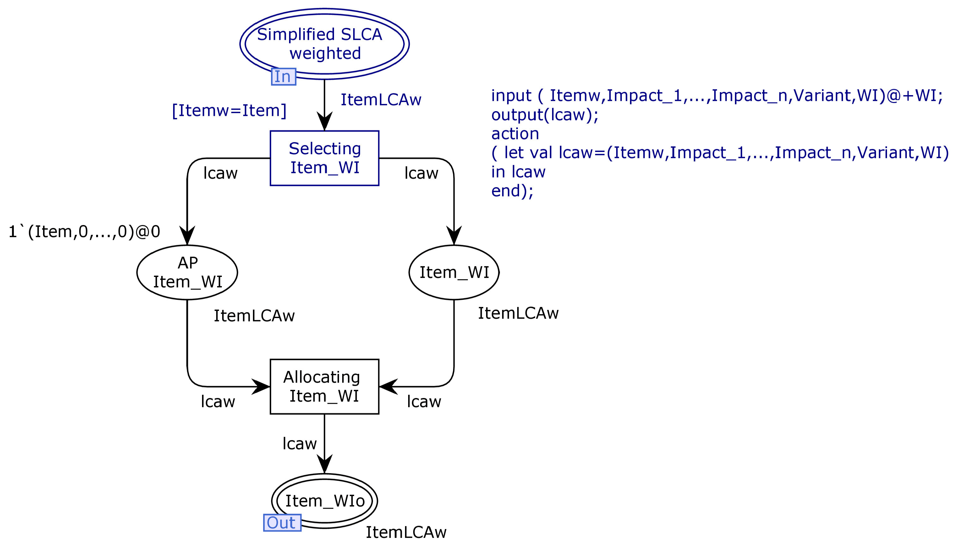
Figure 6 provides a content view of this transition for a given Item:
To separate the weighting results by item’s family, we define a guard condition in Selecting Item_WI transition, specifying that the current Item’s name (Itemw) should be equal to the desired item’s family name (Item).
In this substitution transition, we will create a set of branches equal to the number of items’ families within the ASD, and we will just change the guard conditions allowing the data filtering.
The output is lcaw of type ItemLCAw corresponding to the weighting information for all the variants of this item’s family; it is stored in the place Item_WI.
2.2.3. Selection of the Candidate Ecological Solution
The eco-indicator of an item is the lowest weighted indicator
WI considering all its variants; it is given by Equation (5):
where
k is the number of
variants.
In this step, we select the eco-indicator of each item family using the weighted indicators
WI available in
Item_WI place of
Figure 6.
We stored the value of the different weighted indicators in a timed token with @
+WI. As in Hierarchical TCPN, the token possessing the shorter time will be fired before the others, the item’s variant possessing the lowest weighted indicator
WI: The eco-indicator will be selected first and the transition
Allocating Item_WI of
Figure 6 will be activated.
To avoid successive firing of this transition, an anti-place AP Item_WI is defined, allowing that only one token is processed at a time. Thus, the transition Allocating Item_WI output contains one token, which is the eco-indicator of the Item family, and it is stored in Item_WIo.
Next, we build the design environmental matrix (DEM) of the candidate solution. The DEM is the square matrix of Equation (6), where we place the respective subsystems in rows and columns. It contains information about the candidate ecological solution, including the eco-indicators for each item family.
Let us label its cell, where the row i intersects the column j. We have the following:
If i = j, is the subsystem eco-indicator ().
If i ≠ j, includes the eco-indicator of the link between the subsystem and the subsystem , (). It is equal to zero if this link does not exist.
The mechatronic system’s eco-indicator is calculated using Equation (7), where we aggregate the subsystems eco-indicators and the links eco-indicators from the DEM:
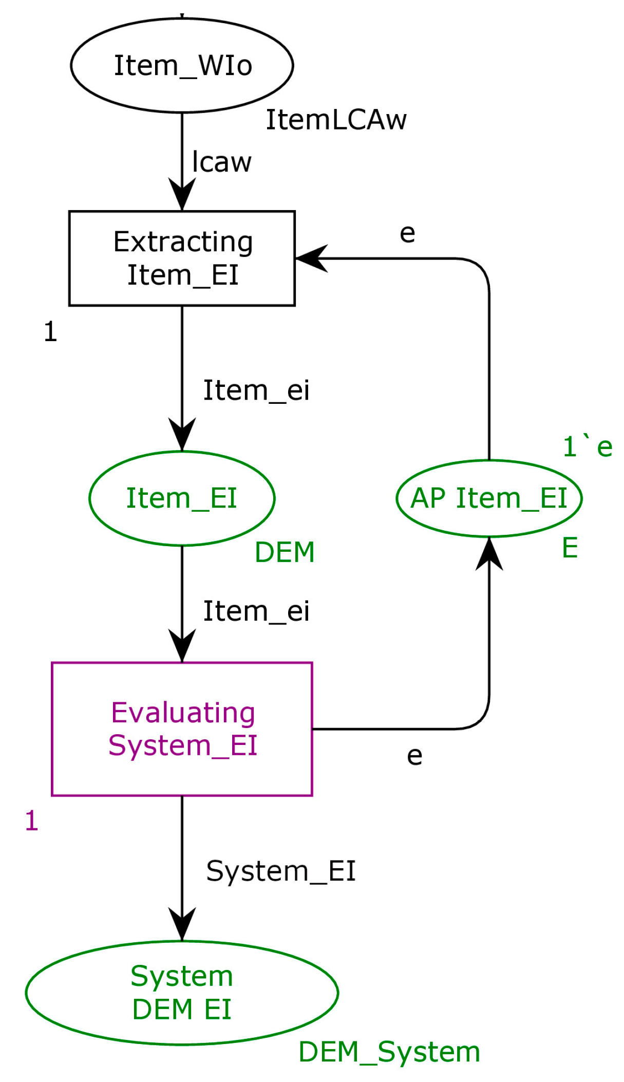
Thus, to construct the DEM using Hierarchical TCPN, we will need information about the different eco-indicators for the items’ families defined within the ASD. For this purpose, the transition
Extracting Item_EI of
Figure 7 is defined with a high priority to avoid concurrency, where a transfer function extracts the data
#(n + 3)lcaw, from the token of type
ItemLCAw, which is equal to the eco-indicator
@+WI. This information is contained in the place
Item_EI of type DEM, which is an integer.
To process a token at a time, an anti-place AP Item_EI is defined for each place of type DEM.
We create similar branches to the ones of
Figure 7 for all the items’ families within the ASD.
To compute the system eco-indicator, we need to obtain all the items’ families’ eco-indicators
Item_EI. The transition
Evaluating System_EI of
Figure 7 is defined for this purpose. It is enabled only if all the different items’ families’ eco-indicators
Item_EI are available. We define a transfer function in this transition to compute the value of the mechatronic system’s candidate solution eco-indicator according to Equation (7), and we store it in the place
System DEM EI of type
DEM_System, which is an integer. High priority is attributed to this transition to avoid concurrency.
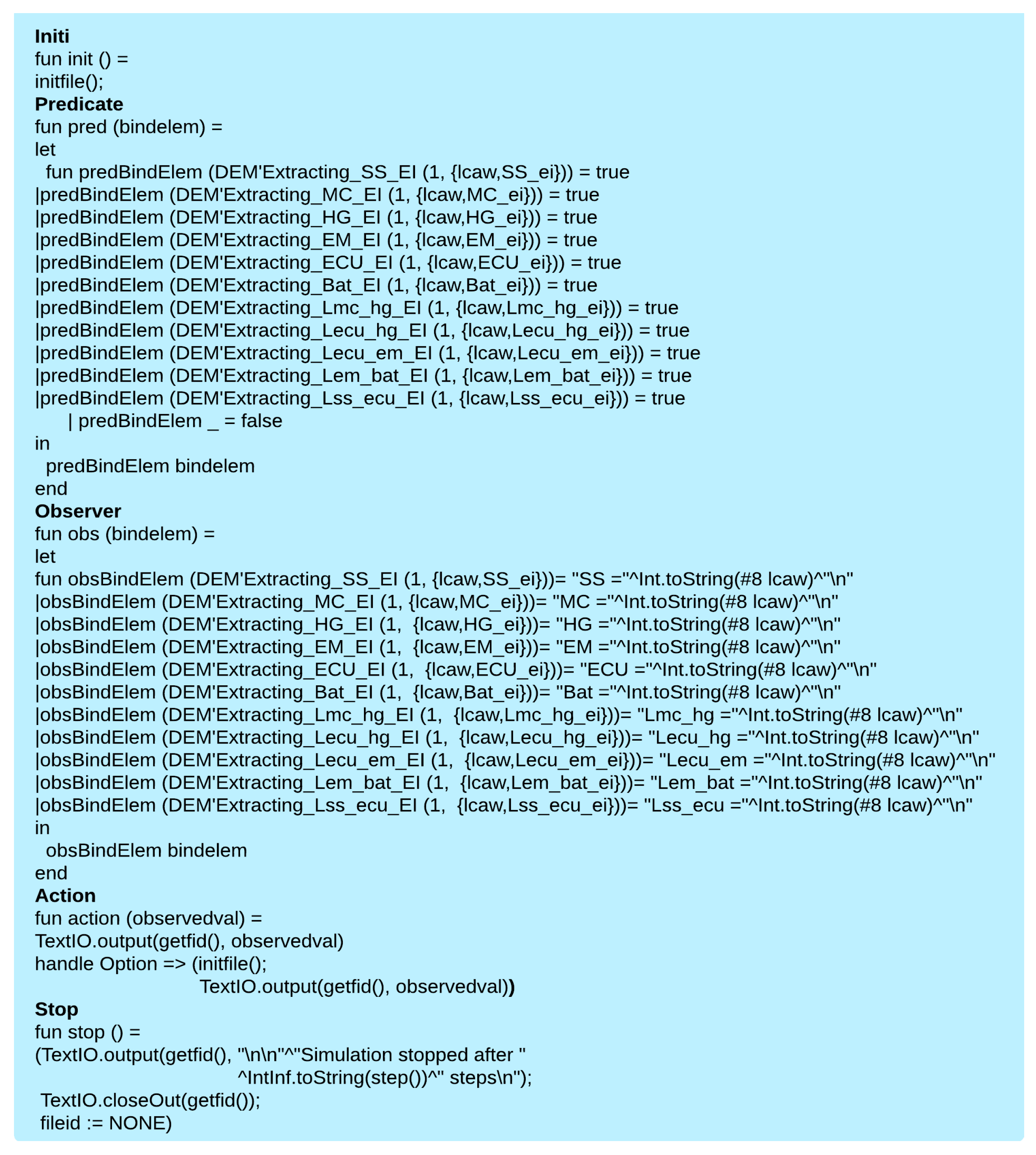
In CPN Tools, monitors can be deployed to examine the binding elements that occur and the markings that are reached during a simulation. To obtain data about the ecological candidate solution, several monitors are defined [
36]:
Write-in file monitors are used to extract information about each item’s eco-indicator and then create the DEM of the whole system. The output is a text file. It is applied to the transition Evaluating System_EI.
We need to identify the variants of the items belonging to the ecological candidate solution. For this purpose, we define user-defined monitors, and we extract the needed information.
Break place content monitor is defined to stop the simulation once obtaining the DEM of the candidate solution, i.e., when a token is present in the place System DEM_EI.
3. Application
We choose RBS, the same application as used in [
21,
22], to illustrate our approach, due to data limitations, in particular regarding SLCAs inventory data. It comprises three mechanical items: a master cylinder, a hydraulic group, and an electrical machine, two electronic ones: a battery and a speed sensor, and a hardware (electronic)/software item: an ECU, and five links:
: The link between the master cylinder and the hydraulic group.
: The bidirectional link between ECU and the hydraulic group.
: The link between ECU and electrical machine.
: The link between the electrical machine and the battery.
: The bidirectional link between the speed sensor and the ECU.
For illustrative purposes, we assume that steps 1 to 3 of
Figure 1 were completed and that we obtained the admissible items listed in
Table 2:
From
Table 2, according to Equations (1) and (2), the admissible subsystems’ combinations
and admissible links’ combinations
are provided by Equations (8) and (9):
Using Equation (3), the admissible solutions’ domain contains 51.840 possible combinations.
In [
22], this number was equal to four. We constructed four DEMs, using weighted indicators instead of eco-indicators presented in Equation (6). Then, we compared the results of the four possible solutions and chose the one processing the lowest system eco-indicator.
Building 51.840 DEMs manually and comparing them is impractical, which explains the need for the generalization of the fourth step 4 the sustainable design methodology.
The impact categories of
Table 3, belonging to the CML Baseline LCIA of OpenLCA software, are selected; the number n of impact categories in our case is equal to 6.
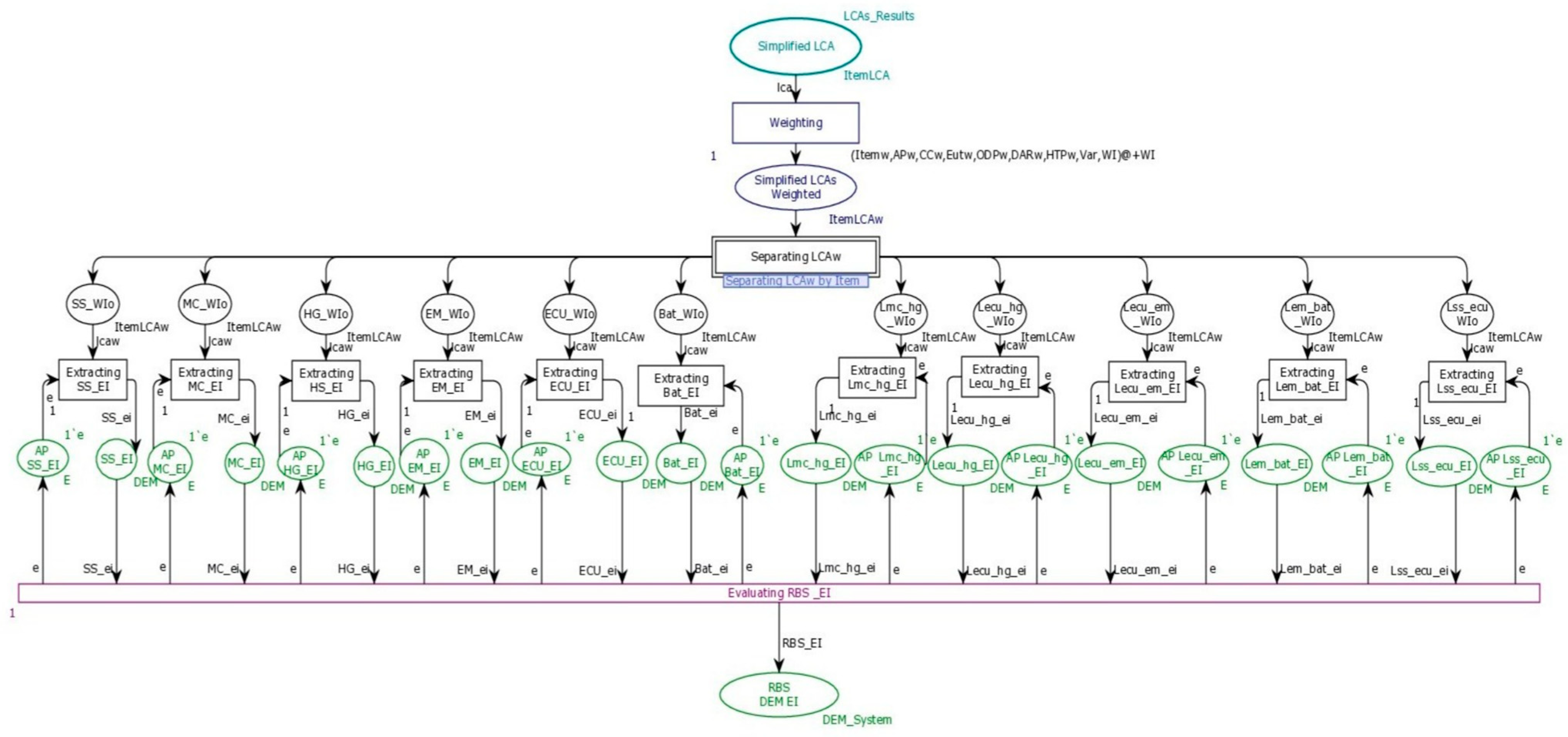
The Hierarchical TCPN model of the RBS is illustrated in
Figure 8; it includes the SLCAs’ results as an input, the weighting process, the separation of weighted SLCAs by family of items, and the selection of the ecological solution:
3.1. Integration of SLCA Results into the Hierarchical TCPN Model
In
Table 2, we obtained a total of 16 subsystems variants and 15 links variants. Thus, we need to conduct 31 SLCAs:
Table 4 is an illustration of SLCA results of an admissible RBS solution within the ASD:
To model this step using the Hierarchical TCPN, we define the input place of
Figure 8:
Simplified LCA of type
ItemLCA; the token
LCAs_Results contains all the 31 SLCAs’ results. For example, the declaration of the variant number 1 of the hydraulic group is given by:
| colset ItemLCA = record ItemName: | |
| HG*AP:3681.41*CC:811.9*Eut:238.25*ODP:92.01*DAR:30.83*HTTP:32.89*Variant:1; | |
3.2. Weighting
After gathering all the SLCA results by item, we define the weighting criteria to be applied. In our case study, the project team specifies that each impact category of the whole system should be reduced to half of its average value obtained from the SLCAs of the 31 items, i.e., we will prioritize items with impact categories less than or equal to the half of their average value obtained from all the SLCAs results.
Table 5 includes the weighting intervals defined for the RBS within the ASD:
For example, the impact category eutrophication of all the 31 items belongs to [0–2000], and their average value is equal to 1200; then, we define three intervals [0,600], [600,1200], and more than 1200, we assign to them the weights 2, 4, and 6, respectively.
Table 6 provides an example of weighting results of the RBS admissible solution of
Table 4 using the weighting instructions of
Table 5.
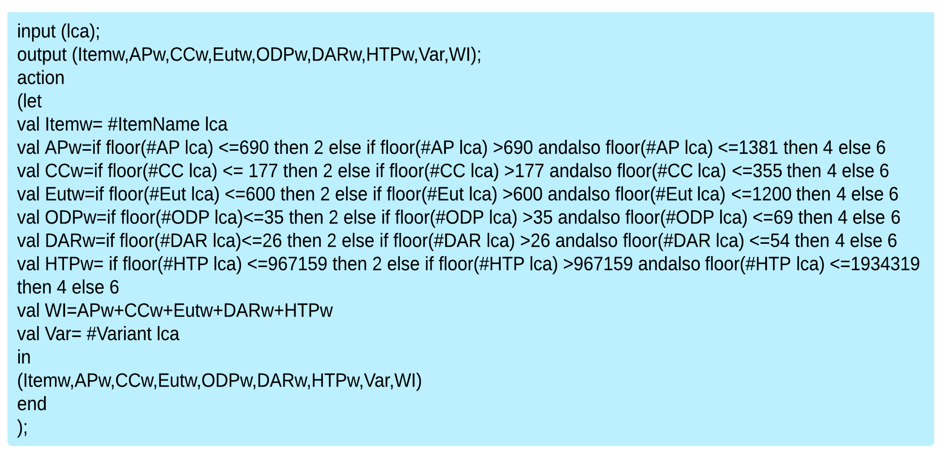
The
Weighting transition of
Figure 8 presents the weighting process. The transfer function of
Figure 9 is defined in the segment code of this transition to weight the different impact categories
AP,
CC,
Eut,
ODP,
DAR,
HTP, and obtain
APw,
CCw,
Eutw,
ODPw,
DARw,
HTPw, for each item according to the weighting intervals of
Table 5. The weighted indicator
WI is then calculated as defined in Equation (4):
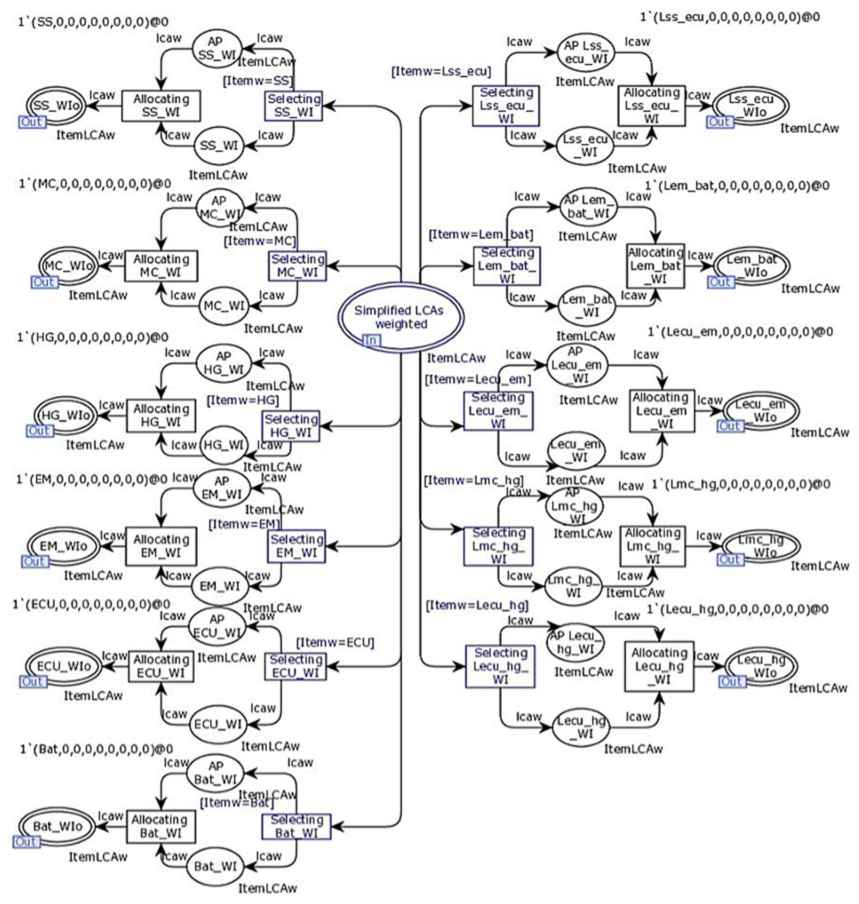
In
Figure 8, the place
Simplified LCAs weighted contains the result of the weighting process including the 31 items of
Table 2. Then, we separate the results by the item’s family using the substitution transition
Separating SLCAw.
Figure 10 provides an insight into the content of this transition; it contains 11 branches corresponding to the RBS’ six subsystems (arranged on the left side of the input place
Simplified LCAs weighted) and five links ‘families (arranged on the right side of the same input place):
The transitions Selecting SS_WI, Selecting MC_WI, Selecting HG_WI, Selecting EM_WI, Selecting ECU_WI, Selecting Bat_WI, Selecting Lmc_hg_WI, Selecting Lecu_hg_CWI, Selecting Lecu_em_WI, Selecting Lem_bat_WI, Selecting Lss_ecu_WI are used to separate the weighting results by item family using guard conditions. For example, in the guard condition of the transition Selecting SS_WI for speed sensor family, we have [itemw = SS].
3.3. Selection of the Candidate Ecological Solution
The different places
SS_WI, MC_WIo, HG_WIo, EM_WIo, ECU_WIo, Bat_WIo, Lmc_hg_WIo, Lecu_hg_WIo, Lecu_em_WIo, Lem_bat_WIo, Lss_ecu_WIo of
Figure 10 contain the weighted indicators of the items and their related weighted impact categories information.
To process an item at once, anti-places AP SS_WI, AP MC_WI, AP HG_WI, AP EM_WI, AP ECU_WI, AP Bat_WI, AP Lmc_hg_WI, AP Lecu_hg_CWI, AP Lecu_em_WI, AP Lem_bat_WI, AP Lss_ecu_WI are defined.
To extract the eco-indicator for each item’s family, we define the transitions
Extracting SS_EI, Extraction MC_EI, Extracting HG_EI, Extracting EM_EI, Extracting ECU_EI, Extracing Bat_EI, Extracting Lmc_hg_EI, Extracting Lecu_hg_EI, Extracting Lecu_em_EI, Extracting Lem_bat_EI, Extracting Lss_ecu_EI of
Figure 8 as well as their anti-places
AP SS_EI, AP MC_EI, AP HG_EI, AP EM_EI, AP ECU_EI, AP Bat_EI, AP Lmc_hg_EI, AP Lecu_hg_EI, AP Lecu_em_EI, AP Lem_bat_EI, AP Lss_ecu_EI to ensure that only one item is processed at a time. High priorities are given to these transitions. As we stored the weighted indicators in the time attribute, the eco-indicators defined in Equation (5) will be selected for each item’s family.
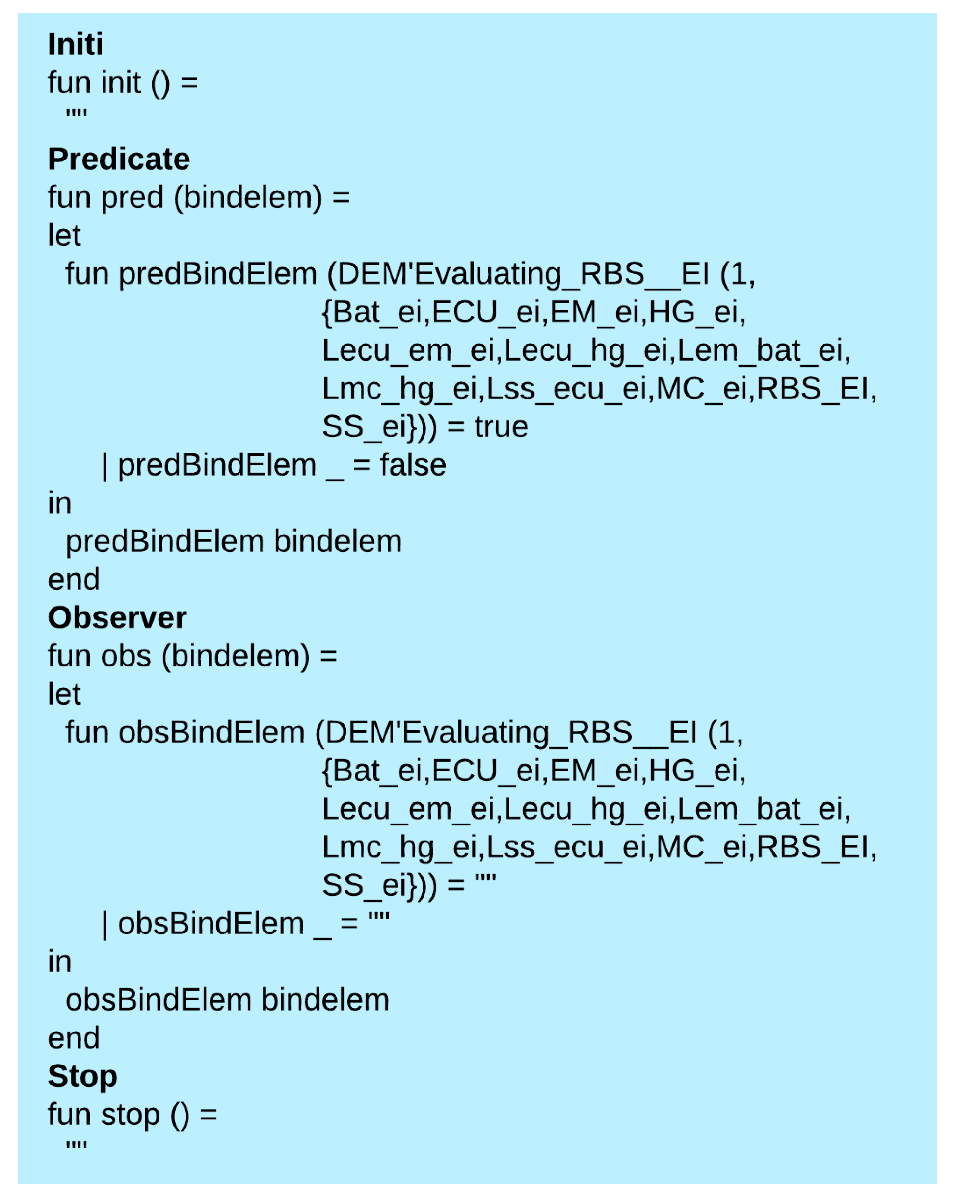
The transition
Evaluating RBS_EI provides the RBS eco-indicator of the candidate ecological solution according to Equation (7) and stores it in the place
RBS DEM EI. To build the DEM as defined in Equation (6), we define the write-in-file monitor depicted in
Figure 11 for this transition:
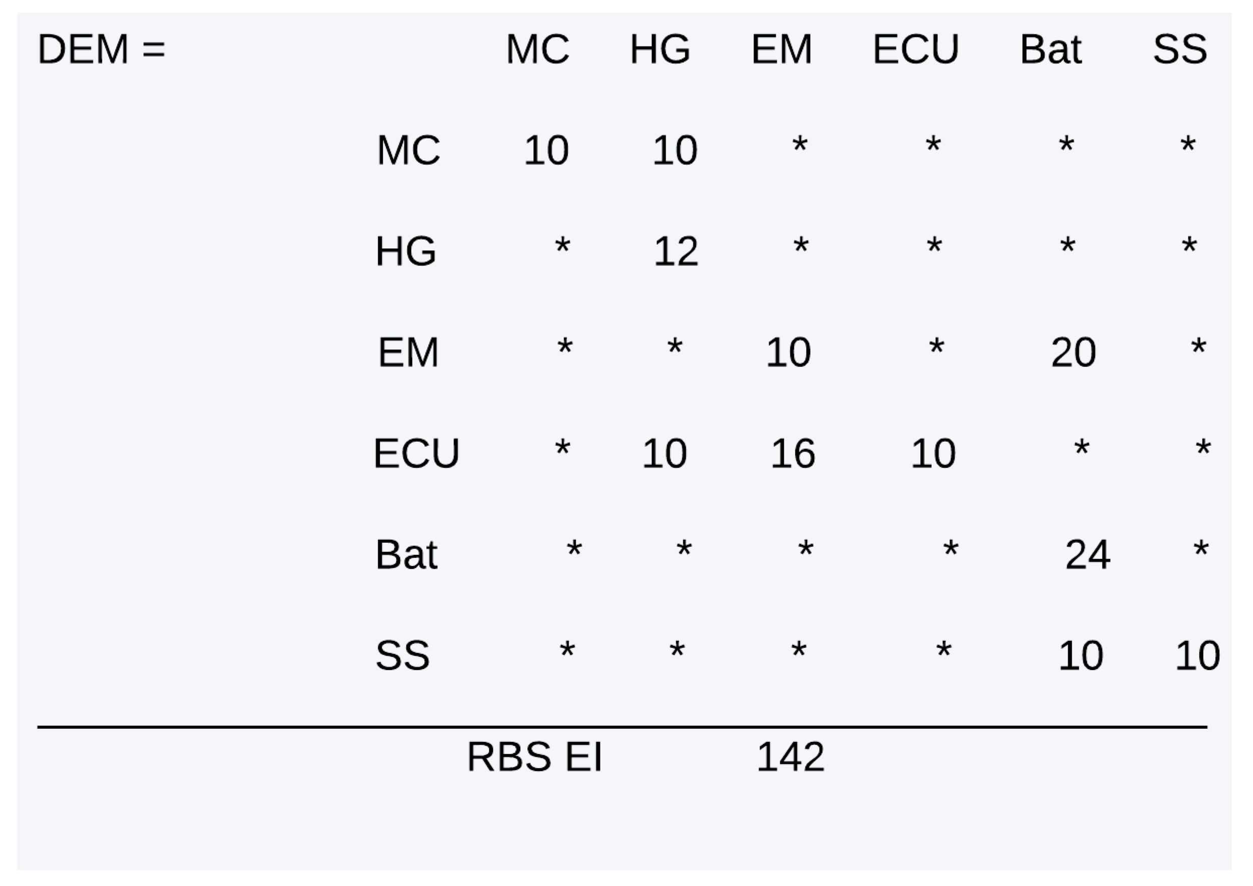
The output of this write-in-file monitor is the DEM of the RBS candidate ecological solution of
Figure 12:
The eco-indicator of the candidate RBS solution is equal to 142. We can derive the individual items’ eco-indicators. For instance, the battery eco-indicator is equal to 24 and the link Lecu_hg eco-indicator is equal to 10.
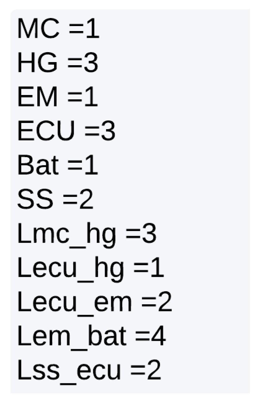
Now, we need to identify the variants of the items belonging to the candidate ecological solution of
Figure 12. For this purpose, we define the user-defined monitor shown in
Figure 13.
This monitor is applied to the transitions
Extracting SS_EI, Extraction MC_EI, Extracting HG_EI, Extracting EM_EI, Extracting ECU_EI, Extracing Bat_EI, Extracting Lmc_hg_EI, Extracting Lecu_hg_EI, Extracting Lecu_em_EI, Extracting Lem_bat_EI, Extracting Lss_ecu_EI of
Figure 8. It provides the results depicted in
Figure 14:
For example, if we choose the master cylinder family, the variant number 1 is the subsystem representing the master cylinder item in the ecological candidate solution.
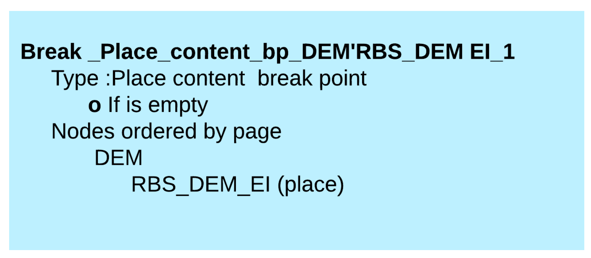
To halt the simulation, we define the break place content monitor of
Figure 15. This monitor stops the simulation once obtaining the DEM of the candidate solution; it is applied on the place
RBS_DEM_EI.
4. Discussion
The proposed approach allows the identification of the mechatronic solution that satisfies a set of ecological criteria, from several potential solutions. These criteria could be defined internally or by the stakeholders.
The environmental dimension leading to the choice of the candidate solution is incorporated in the last phase of the design process, without disrupting the conventional workflow of the mechatronics designers, but merely by adding a last step. Regardless of the method employed to obtain the ASD, it could be different steps than 1, 2, and 3 already presented in [
22]; it is possible to apply the present methodology to obtain the candidate ecological solution.
Due to data availability constraints, SLCAs applied in the production phase are deployed in the illustrative case. It is recommended to implement SLCAs covering the entire life cycle: production, use, and end of life, to obtain results that are more accurate and thus be able to make a finer decision. Indeed, a given item could have a more significant environmental impact at the end of its life than during its production and use and conversely. We chose OpenLCA software for illustrative purposes. Other LCA software could be used, such as Gabi and SimaPro. The most important factor is to adopt a unified LCIA and LCA software throughout the project.
Even if the software item is considered immaterial, it certainly has an environmental impact on its associated hardware item. It plays an important role in energy consumption management and the generation of waste. This impact is considered when defining the inventory input data of the associated hardware.
In the design phase, it is crucial to define design criteria (steps 1 to 3) of [
22] and refine them for the project, because they have an immediate impact on the results of the SLCAs. For instance, the maintenance strategies to be adopted for the mechatronic system can extend the lifetime of some items by reducing the frequency of replacement and helping in reducing unnecessary resources’ consumption, as is the case of preventive maintenance. Or it could impact the results negatively by increasing corrective interventions where inefficient energy is utilized, and waste is generated.
LCAs, even simplified ones, require both time and resources. Within the framework of a customer–supplier agreement, standardized SLCAs, using a unified LCIA and LCA software, could be proposed and incorporated as part of the specifications communicated to suppliers, giving them responsibility for developing the SLCAs to further reduce the assessment time.
The weighting process provided in the application case serves as an illustration and seeks to reduce all the impact categories of the whole system to half of their average value in line with the results obtained from the SLCAs for all the items within the ASD. We could modify the weighting criteria according to the project objectives.
The outlined approach addressed the entire life cycle of the designed mechatronic system. It allows the use of the SLCA analytical tool as in [
9,
10]. The weighting process enables the definitions of environmental impact reduction targets according to variable criteria. This may involve focusing on a specific aspect of the product life cycle like in [
11,
12,
13,
14,
15,
16,
17] or selecting reduced impact materials as in [
16] or reutilizing the system at the end of their life, as in [
14].
The hierarchical TCPN enables the selection of the candidate RBS solution among several possible solutions. The model could be tailored to suit any desired number of items’ families. It allows thus the generalization of the proposed approach in [
22] to any size of possible solutions.
Since the number of admissible solutions was equal to four in [
22], we constructed four DEMs manually based on the weighted indicators, and we compared them to obtain the candidate ecological solution. In the presented case study, the number of possible solutions is equal to 51.840, and we are able to conclude directly the DEM of the candidate ecological solution containing the different items “eco-indicators” via CPN Tools monitors and simulations.
The data offered by the DEM, particularly the item-specific eco-indicators, provide us with an indication of items with a relatively high environmental impact. Action plans could be drawn up for key items to improve the whole mechatronic system’s eco-indicator.
5. Conclusions
The rapid pace of mechatronics development in many countries invites us to consider their impact on our ecosystems. It is therefore crucial to address the environmental sustainability of any new mechatronic product from the earliest design stages. This work introduced an approach to promote environmental dimension when applied to a large set of admissible mechatronic systems solutions resulting from the design phase using hierarchical TCPN and SLCAs. The methodology allowed the selection of the candidate ecological mechatronic system from a large set of possible solutions derived from the design phase. First, we performed SLCAs for each item belonging to the ASD, and we incorporated their results into the hierarchical TCPN model; then, we weighed them via a weighting process to enable comparison of the obtained results, given that the impact categories of a chosen LCIA are heterogeneous. After the weighting process, a weighted indicator is associated with each item and is assigned to temporal attributes in the hierarchical TCPN model. The results were classified according to the items’ families. Next, for each item’s family, we selected the lowest weighted indicator, which was named the eco-indicator. Lastly, we constructed the DEM of the ecological solution using the different items eco-indicators and concluded the involved items variants through defined monitors. The methodology was applied to an RBS. We were able to identify the candidate ecological solution among 51,840 possible ones.
Future work will focus on extending the hierarchical TCPN model to cover all the sustainable design stages of the overall sustainable design methodology (steps 1 to 3), and particular attention will be paid to the resources management required to carry out the eco-design project, which is directly correlated with time and resources availability.
We have assumed in this paper that mechatronic systems have a frozen design structure. We will extend the eco-evaluation step to cover mechatronic system solutions involving variable design structures.
The design phase covers multiple criteria having a substantial impact on SLCA results and, therefore, on the eco-indicator of the whole mechatronic system. Among those criteria, we can cite the dependability ones. We have already presented a TCPN model for predicting the reliability, availability, and maintainability of mechatronic systems. We will examine the potential for integrating it with the model developed in this paper for the purpose of assessing the impact of dependability criteria, considered in the design phase, on the results of SLCAs and, subsequently, on the DEM and the eco-indicators of mechatronic solutions.

