The built prototype has been used in a testing campaign to check its feasibility and to characterize its performance, looking at features fulfilling main requirements for a low-cost comfort and easy user-oriented operation.
3.1. Testing Model
The feasibility and characterization of the operation performance of the proposed exoskeleton in assisting finger motion are discussed, referring to testing modes in
Figure 9 and
Figure 10 with test results in
Figure 11,
Figure 12,
Figure 13,
Figure 14,
Figure 15,
Figure 16,
Figure 17,
Figure 18 and
Figure 19 using sensors that equipped the exoskeleton in terms of motion and power consumption. Those results well represent the kinematic features of the exoskeleton mechanism in conjunction with the dynamics driven by the servomotor power and cable tension. The theoretical analysis that is mentioned with the scheme of
Figure 6 and
Figure 7 is included since those results will not add any specific additional information to being well matched with the test results.
Tests have been designed to check the prototype with a human finger and an artificial finger to have results from different views, such as related to human usage and to functional application. Testing mode consists of motion assistance in the extension–flexion movement of the index finger of the left hand as per the design of the finger exoskeleton with the guiding pulley on the left side of the support.
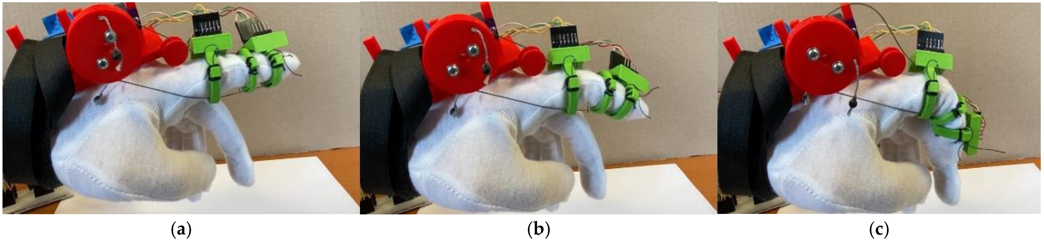
For tests with the prototype using a human finger, a user wears the glove with the device support that is fixed on its top as shown in
Figure 9. Then, the cables are adjusted to the correct length according to the user’s finger anatomy, and finally, they are activated by switching on the device. The pulley size has been sized to allow a 180 deg rotation referring to a complete finger flexion. For a user with a finger approximately 10 cm long, the built prototype fits very well, as shown in
Figure 9. This satisfactory result in full extension that is followed by complete flexion of the assisted finger is illustrated in the snapshot of
Figure 9.
Figure 9.
Snapshot of a test with the prototype of a finger exoskeleton in assisted extension–flexion motion of a human finger: (a) intial configuration; (b) intermediate configuration; (c) final configuration.
Figure 9.
Snapshot of a test with the prototype of a finger exoskeleton in assisted extension–flexion motion of a human finger: (a) intial configuration; (b) intermediate configuration; (c) final configuration.
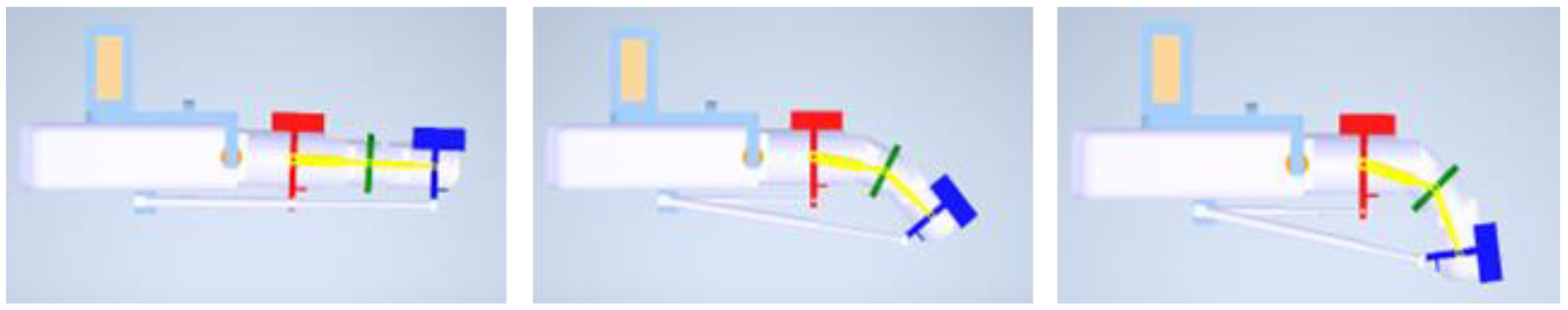
For tests with an artificial finger, the device support and pulleys have been resized and adapted to a 1.5 scale as shown in
Figure 10. Additionally, the motor is selected differently for larger sizes. The testing follows the same protocol as for the prototype with a human index finger in
Figure 9. The experienced behavior shows very good results with the artificial finger’s movement closely reproducing the flexion of a healthy human index finger, as illustrated in the snapshot of
Figure 10, that is comparable with that one in
Figure 9.
Figure 10.
Snapshot of a test with the prototype of a finger exoskeleton in assisted extension–flexion motion of an artificial finger. (a) intial configuration; (b) intermediate configuration; (c) final configuration.
Figure 10.
Snapshot of a test with the prototype of a finger exoskeleton in assisted extension–flexion motion of an artificial finger. (a) intial configuration; (b) intermediate configuration; (c) final configuration.
3.2. Test Results
During the motion tests conducted with the two solutions presented above in
Figure 9 and
Figure 10, various sensors were positioned on the finger exoskeleton mechanism to monitor the exoskeleton behavior accurately. Like in the previous prototype ExoFinger [
6,
10], two IMUs were placed on the finger rings as follows: one on the proximal phalanx and the other on the distal phalanx. Additionally, a current sensor was connected in series with the motor to monitor the power consumption. These sensors continuously provide six data sets as follows: angular velocity around the X, Y, and Z axes of the IMU reference and linear acceleration along these axes yet. The angular velocity helps to identify when the finger starts moving, but it does not provide insightful information about the finger’s behavior and movement. But linear acceleration offers the most valuable data since it refers to the kinematics of the assisted motion.
Test results with a human finger, as in
Figure 9, are reported in
Figure 11,
Figure 12,
Figure 13,
Figure 14 and
Figure 15, and those with an artificial finger, as in
Figure 10, are shown in
Figure 16,
Figure 17,
Figure 18 and
Figure 19.
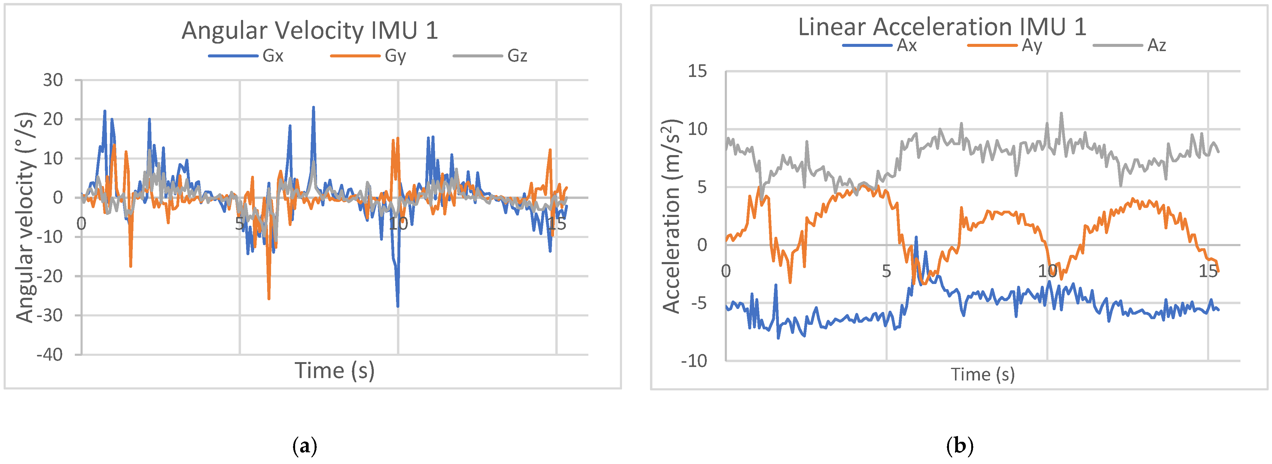
Referring to a test with a human finger, in
Figure 11a, the assisted motion is detected in angular velocity with consistent numerical noise, very likely due to the tremor functioning of the assisted finger motion following the not sufficiently smooth cable actuation. However, it can be noted a cyclic acquisition of the data corresponding to the flexion–extension of the assisted finger with primary motion in the sagittal plane indicated by angular velocities around X and Y IMU axes. In
Figure 11b, during the first two seconds of the test, the linear acceleration fluctuates rapidly over short periods, corresponding to the motor’s initialization phase since it automatically positions itself at the starting point. Subsequently, the acceleration follows a sinusoidal pattern with a period of about 4 s, especially along Y and Z axes, which are the primary axes of movement since the assisted finger moves in the finger sagittal plane. The motion is well detected with Y acceleration as referring to the main motion component showing the three cycles on flexion–extension of a test. The acceleration along the X-axis with nonzero values indicates that the finger does not move with a planar movement in the sagittal plane, but it is slightly twisted. The acquired sinusoidal pattern clearly illustrates the finger’s flexion and extension movements along the Y-axis as follows: when the acceleration is positive, the finger is in a descending flexion phase, and when it is negative, the finger is in an ascending extension phase.
Figure 11.
Results acquired by IMU 1 in
Figure 8 from a test with a human finger in
Figure 9: (
a) angular velocity and (
b) acceleration components.
Figure 11.
Results acquired by IMU 1 in
Figure 8 from a test with a human finger in
Figure 9: (
a) angular velocity and (
b) acceleration components.
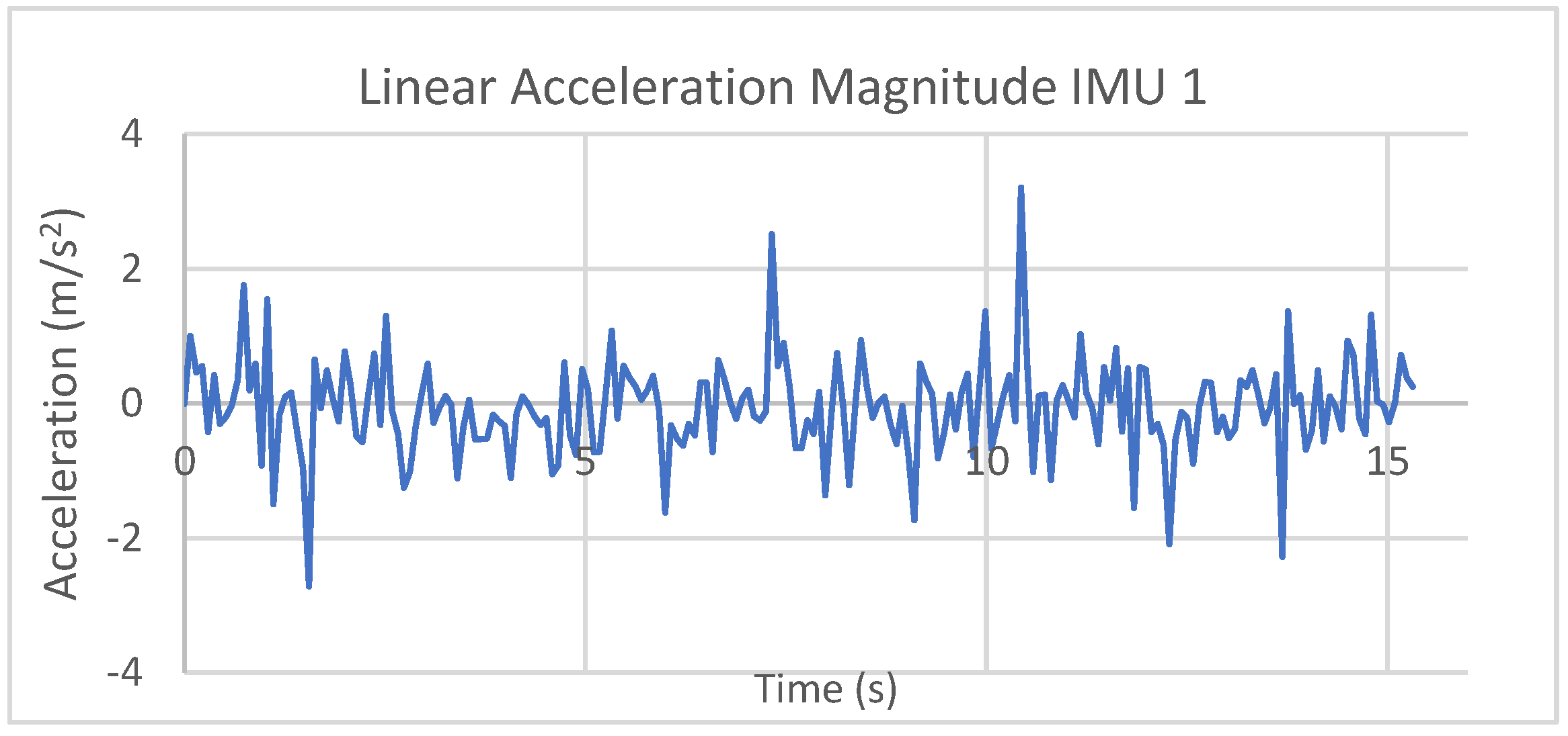
Considering the IMU axis reference in
Figure 8b, the magnitude of the linear acceleration can be calculated free of gravity by A = (Ax
2 + Ay
2 + Az
2)
0.5 − g (being g the gravity acceleration), with results in
Figure 12. The computed values are limited within a range of ±1 m/s
2, indicating, in general, small values of a smooth assisted motion but with a few sudden changes, as reported by acceleration peaks corresponding mainly to the inversion of the motion from flexion to extension of the assisted finger.
Figure 12.
Computed acceleration magnitude from results acquired by IMU 1 in
Figure 8 during a test with a human finger in
Figure 9.
Figure 12.
Computed acceleration magnitude from results acquired by IMU 1 in
Figure 8 during a test with a human finger in
Figure 9.
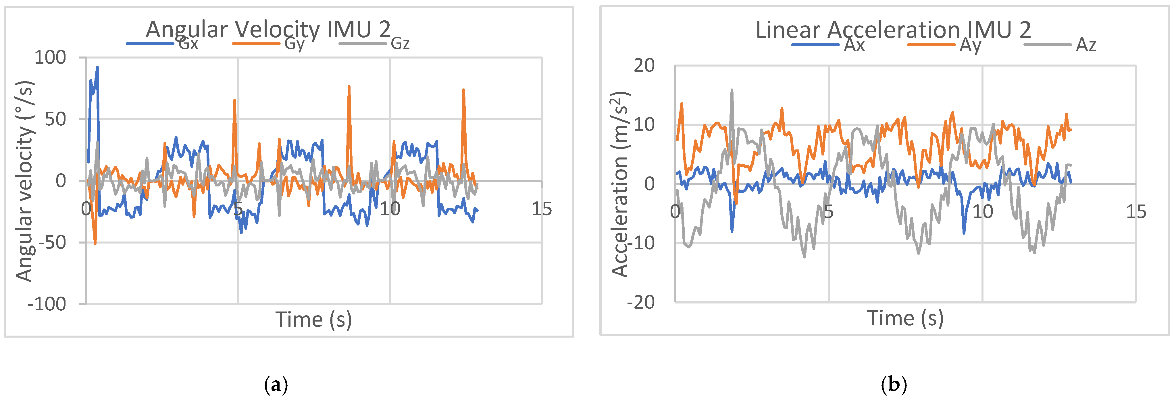
Similarly, the acquired values are from IMU 2 on the middle phalanx,
Figure 8, but with some different results, mainly in angular velocity. For the proximal phalanx, the movement is detected as a 60° rotation around the MIP joint with more evident characteristics both in values and cyclic displacements, being the main phalanx involved in the flexion–extension motion. Significant rotation and therefore angular velocity are around the
X-axis of IMU2, as shown in
Figure 13a. Regarding the linear acceleration of the distal phalanx in
Figure 13b, the large values along the X axis indicate a slight misalignment from the sagittal plane as per the not-fully-correct wearing of the distal ring as shown in
Figure 9 since the IMU2 house is slightly rotated. Nevertheless, the behavior of the flexion–extension motion is still detected with its cyclic timing, likewise the values along the Y axis, but in counter phase. The values along the
Y-axis illustrate the finger moving forward and backward horizontally during the flexion–extension motion. Along the
Z-axis, the values refer to the finger distal phalanx moving up and down vertically with rather small acceleration values. When the Ay value is at its minimum, it corresponds to the maximum of the Az values, indicating that the finger is extended and raised towards its horizontal position. These acquired data of the acceleration components, as shown in
Figure 13b, well characterize the movement of the distal phalanx of the finger during the tested finger flexion–extension motion.
Figure 13.
Results acquired by IMU 2 in
Figure 8 from a test with a human finger in
Figure 9: (
a) angular velocity and (
b) acceleration components.
Figure 13.
Results acquired by IMU 2 in
Figure 8 from a test with a human finger in
Figure 9: (
a) angular velocity and (
b) acceleration components.
Similar to the acquired IMU 1 acceleration data, the magnitude of acceleration of the distal phalanx from IMU2 can be calculated as shown in
Figure 14 using the formula for free gravity computation. In the plot, peaks with significant variation over the average range within ±1 m/s
2 occur around 4 s, 7 s, and 12 s when Az reaches its maximum, indicating that the finger is extended horizontally when starting the inversion of the motion during the cyclic test exercise.
Figure 14.
Computed acceleration magnitude from results acquired by IMU 2 in
Figure 7 during a test with a human finger in
Figure 8.
Figure 14.
Computed acceleration magnitude from results acquired by IMU 2 in
Figure 7 during a test with a human finger in
Figure 8.
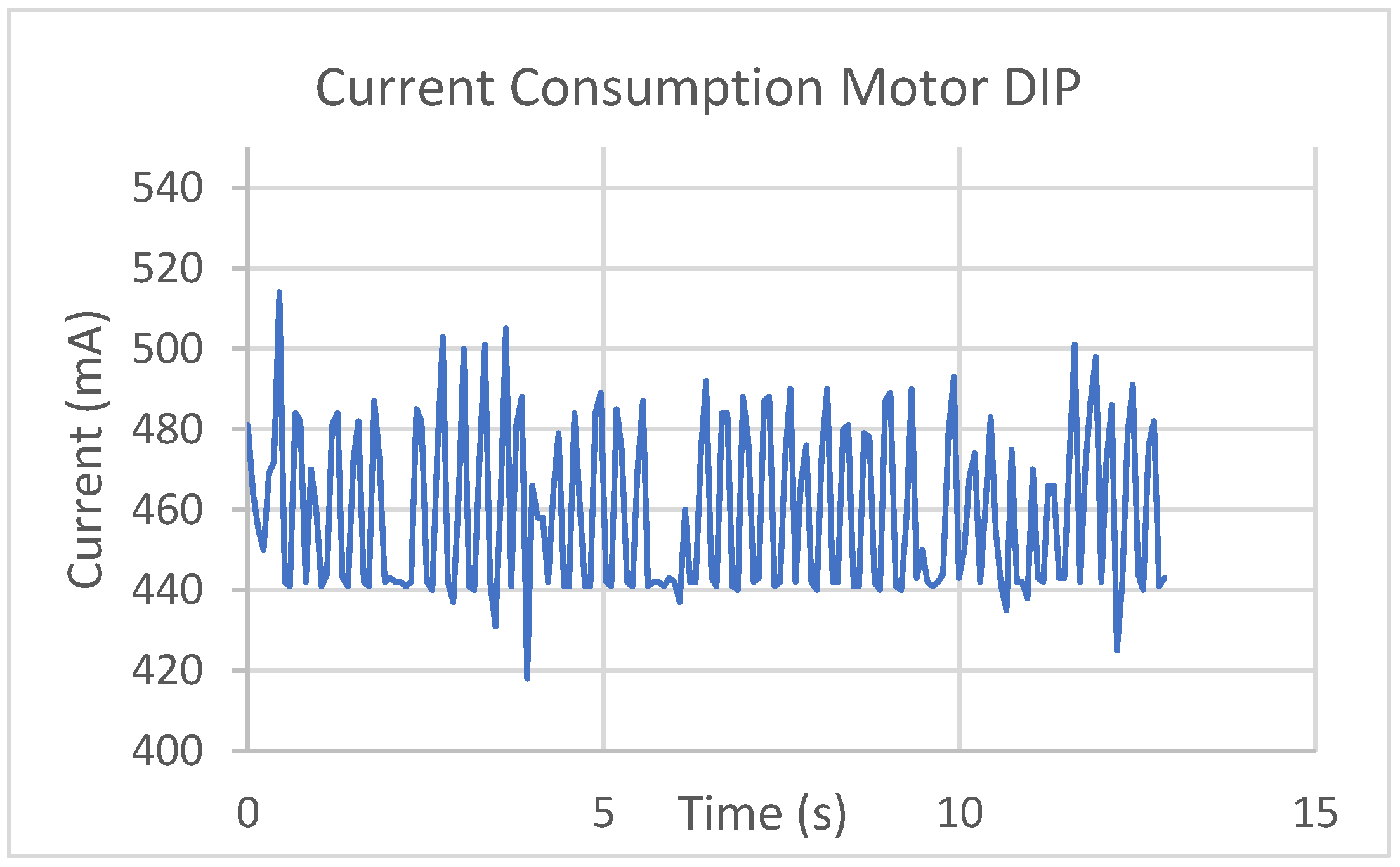
In
Figure 15, data are reported as acquired by the current sensor that is connected in series with the motor to measure the motor’s current consumption when powered by a 5V supply. The results show a variation between 420 mA and 500 mA, which is a consistent energy consumption for the used small motor, indicating active assistance on the finger motion. This level of power consumption ensures sufficient torque, enabling the motor to transmit a significant force through the cables to guide the assisted finger during the prescribed cyclic motion during the test in
Figure 9.
Figure 15.
Results acquired by IMU 1 in
Figure 8 as current consumption from a test with a human finger in
Figure 9.
Figure 15.
Results acquired by IMU 1 in
Figure 8 as current consumption from a test with a human finger in
Figure 9.
The same tests on the human finger as in
Figure 9 were conducted with the artificial finger as in
Figure 10, obtaining comparable results, as shown in
Figure 16,
Figure 17,
Figure 18 and
Figure 19. The data from IMU 1, placed on the proximal phalanx, are shown in
Figure 15, referring to angular velocity, and in
Figure 16b, referring to linear acceleration. The angular velocity is detected with a time history very similar to that acquired for the human finger in
Figure 13a. It is to note that the finger’s rotation occurs around the
X-axis, with detected values within ±12°/s that are smaller than in the case with the human finger, while the other components are measured with similar values. This can indicate that there is no additional motion due to the finger structure due to finger action, as it is indeed detected also with the acquired acceleration reported in
Figure 16b. The finger movement occurs in the YZ plane and effectively illustrates the rotation around the MCP joint with Ay and Az values referring to the cyclic finger flexion–extension motion during the simulated test.
The motion is well detected with Y acceleration as referring to the main motion component showing the three cycles on flexion–extension of a test. The acceleration along the X-axis is also obtained with nonzero values, indicating that the finger does not move with a planar movement in the finger sagittal plane, but it is slightly twisted as also probably due to the not-exact location of the IMU sensor in a horizontal posture. The obtained cyclic time evolution of the components Ay and Az with similar values with respect to the test with the human finger clearly illustrates the flexion and extension movements with some numerical noise and small peaks very likely due to backlash and friction in the wood finger model.
Figure 16.
Results acquired by IMU 1 in
Figure 8 from a test with the artificial finger in
Figure 10: (
a) angular velocity and (
b) acceleration components.
Figure 16.
Results acquired by IMU 1 in
Figure 8 from a test with the artificial finger in
Figure 10: (
a) angular velocity and (
b) acceleration components.
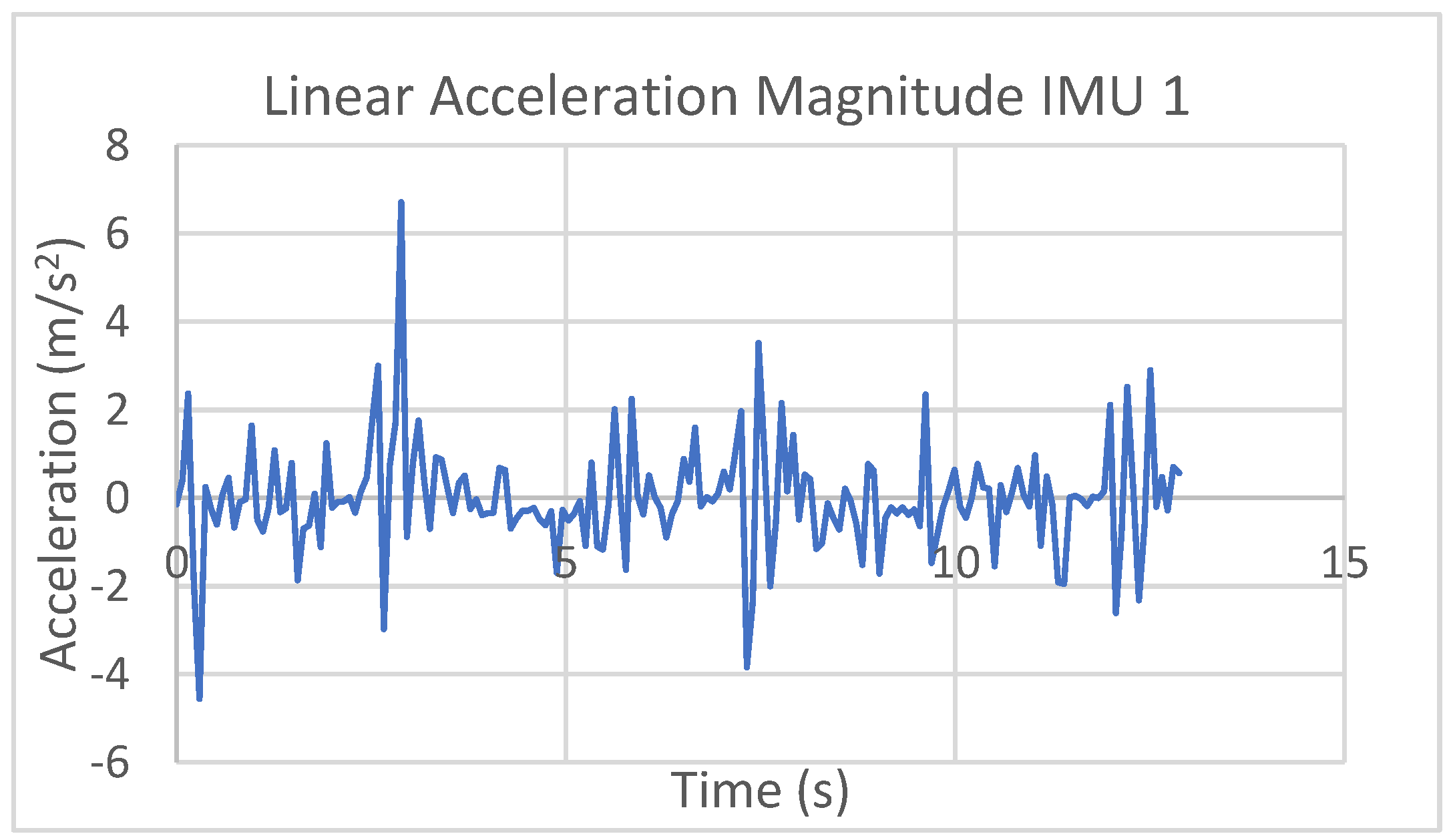
The magnitude of the linear acceleration is calculated free of gravity, as shown in
Figure 17, with values that are limited within a range of ±2 m/s
2 with small values but a little larger than in the test with a human finger. This indicates smooth assisted motion but with a few sudden changes as acceleration peaks, corresponding mainly to the inversion of the motion from flexion to extension of the assisted finger.
The acquired values from IMU 2 of the angular velocity of the middle phalanx are reported in
Figure 18a with some small differences in values and time evolution with respect to those from tests with the human finger as probably due to both the active participation of the finger during human tests and model limitations in the finger design and operation. The major values are detected with respect to the X axis within a range of ±40°/s, confirming the operation in the sagittal plane with small error movements with the respect to X axis. The reported peaks are produced by unexpected lateral motion of the artificial finger due to its mechanical design with free revolute joints among the phalanx bodies. Still evident are characteristics of cyclic displacements since the distal phalanx is the one mainly involved in the flexion–extension motion.
Figure 17.
Results acquired by IMU 1 in
Figure 8 as acceleration magnitudes from a test with an artificial finger in
Figure 10.
Figure 17.
Results acquired by IMU 1 in
Figure 8 as acceleration magnitudes from a test with an artificial finger in
Figure 10.
In
Figure 18b, the linear acceleration of the distal phalanx is reported with the large cyclic values along the Z axis in a ±10 m/s
2 range with a time history of Ay along the Y axis in a 0 to 10 m/s
2 range, well representing the flexion–extension motion of the finger imposed in the simulated test. While Ay is computed with similar values to those of the human test, the values of Az show differences with smaller values in the area of negative values, indicating very likely an active participation of the human finger in a test differently from what is simulated with the artificial finger. The very small values of Ax along the X axis indicate a satisfactory motion in a sagittal plane as already detected in the computed results for the angular velocity. These acquired data of the acceleration components, as shown in
Figure 18b, well characterize the assisted movement of the finger distal phalanx during the simulated finger flexion–extension motion.
Figure 18.
Results acquired by IMU 2 in
Figure 8 from a test with an artificial finger in
Figure 10: (
a) angular velocity and (
b) acceleration components.
Figure 18.
Results acquired by IMU 2 in
Figure 8 from a test with an artificial finger in
Figure 10: (
a) angular velocity and (
b) acceleration components.
In
Figure 19, the current consumption of the motor for the artificial finger is computed close to 500 mA also with a time history like in the case of human finger tests. This current is relatively low for the motor of the selected size in the simulation, but it is larger than the one used in the prototype with the human finger.
Figure 19.
Results acquired by IMU 1 in
Figure 8 as current consumption from a test with an artificial finger in
Figure 10.
Figure 19.
Results acquired by IMU 1 in
Figure 8 as current consumption from a test with an artificial finger in
Figure 10.
The results of the simulated operation with the artificial finger are very similar to those obtained with the tests with the human finger, indicating that the tested operation well represents the operation of the designed cable-driven finger exoskeleton in assisting a human finger. The most significant difference between the two reported tests is that the values are larger in the case of the artificial finger. This is expected since the artificial finger is 1.5 times larger than the human finger, leading to correspondingly larger values for both angular velocity and linear acceleration. Thus, the prototype is unlikely to cause any issues for a user as the assisted movements it produces are not harmful. The tested movements required of the user are comparable to those of a human finger in daily activities and are therefore not traumatic.
The simulated tests with the artificial finger, whose results have confirmed the results from laboratory tests with human fingers, have clarified the successful assistance of the designed cable-driven finger exoskeleton with reasonably satisfactory finger-assisted motion since the artificial finger simulates the operation with no active or reactive finger as it could occur with the human fingers of the volunteers. This ultimately indicates that the designed cable-driven finger exoskeleton is unlikely to cause any risk for a user since the assisted motion is not harmful.
The tests reported with their characterization through the acquired characteristics are examples that are selected from those carried out with tests repeated at least three times each. The purpose of these tests is the validation of the feasibility of the proposed solution and its functional characterization that meets the expectations of motion assistance for fingers. A future development of the study is planned with an experimental campaign with an adequately high number of subjects and test modes that can definitively characterize the suitability of the proposed exoskeleton for physiotherapy and motion exercise applications, also considering long-term efficiency issues.


