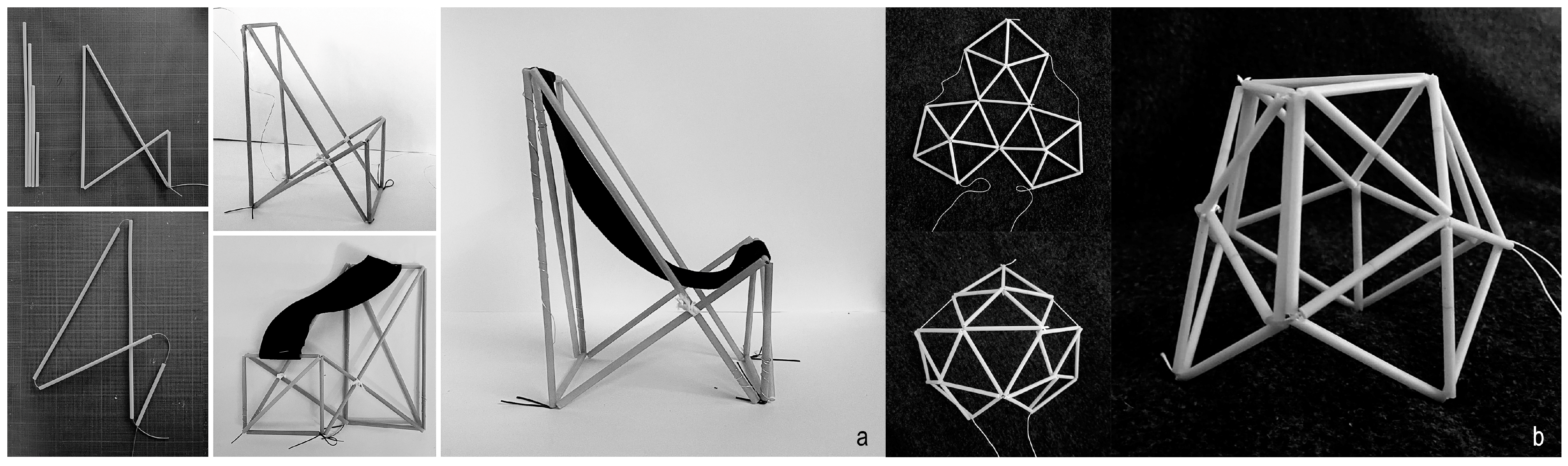
The successful realisation of the Delta IXI concept in a small-scale structural prototype confirmed its adaptability, stability, and capacity to support significant loads relative to its lightweight design. Its adjustable configurations highlighted the system’s versatility and potential for reconfigurable applications. These findings have been encouraging for the potential expansion and integration of the concept into larger architectural applications. While manual adjustments in the first case study were effective in a furniture application, scaling up the system might introduce practical limitations, prompting the development of a kinetic system. Given the system’s inherent deployability, it is particularly suited for kinetic designs and dynamic applications. Therefore, further research explored the adaptation and scaling of the system for implementation as part of an architectural facade, considering the structural and material insights gained from the previous case study.
4.1. Design and Modularity
The design focused on modularity, multiplying units to cover a designated facade area and creating an adaptive system that dynamically responds to weather conditions, particularly the sun’s position. To ensure effective shading, the system included a supporting grid structure and a kinetic mechanism for precise actuation and deployment. An electronically controlled system was developed to enhance functionality and automation. An additional element was incorporated to improve shading performance, adding both functionality and aesthetic value to the system.
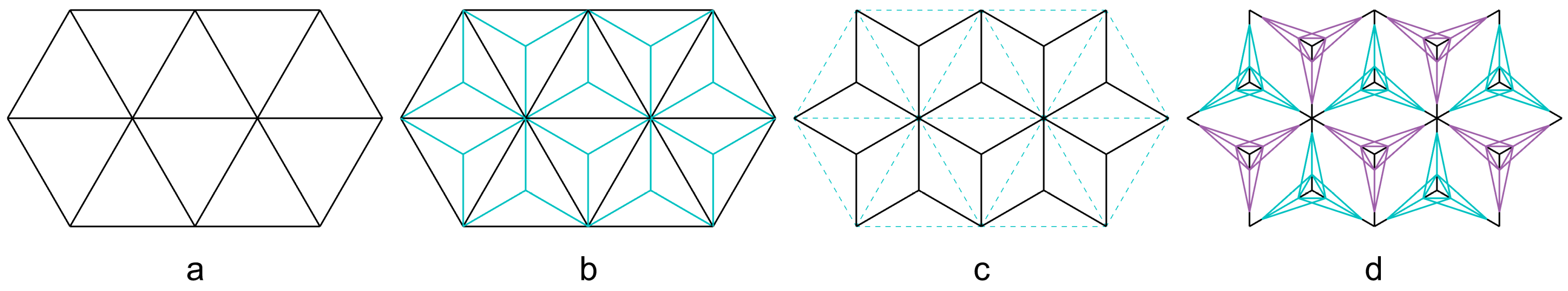
The deployable model, Delta IXI, functioned as a modular and scalable system, capable of expanding both horizontally and vertically within a customised grid. The grid, designed as a structural framework, adopted a triangular arrangement of equilateral triangles, aligning with the model’s geometric principles. The vertices of each triangle acted as key intersection points for the modules in their flat configuration, with the three amplitudes guiding movement during deployment. As the modules were attached solely to these amplitudes, the original grid became redundant. The amplitudes then functioned as sliding rails for the facade components. The final supporting grid, formed from these amplitudes, created a tessellated cubic structure, streamlining the framework and enabling module integration in two directions. The grid’s transformation is illustrated in
Figure 16. Beginning with the triangular grid (a), the blue lines indicate the triangle’s amplitudes (b), which become the primary grid elements (c). On this new grid, multiple Delta IXI modules can be attached. To achieve full coverage, the modules are arranged in two distinct orientations, rotated 180°, as shown in blue and purple (d). This configuration ensures seamless facade coverage when the modules are deployed. The design allows for flexibility, as both module size and grid layout can be adjusted to meet different facade requirements.
The material used for the profiles was previously tested for its mechanical properties in earlier work (as indicated in
Section 1.1), demonstrating its suitability for structural applications. Additionally, the design of the Delta IXI module was assessed for its load-bearing capacity. In the facade application, no direct load scenario is present, so at this stage, the material and system are considered adequate for implementation. A key design limitation lies in the maximum possible length of a single pultruded profile, restricted to 2 m, as confirmed by bending tests. The main Delta IXI module can be adjusted and multiplied to accommodate different facade sizes. While in the furniture-scale scenario, the module size was determined by ergonomics and functionality; the facade application offered greater flexibility, with dimensions varying based on design requirements, overall coverage, and structural considerations.
To enable adaptability, parametric modelling was integrated, allowing precise control over module sizing and grid configurations. A parametric model was developed using McNeel’s Rhinoceros 7.0 and Grasshopper 3D to enhance design flexibility and customisation. This model followed a two-phase approach to ensure adaptability.
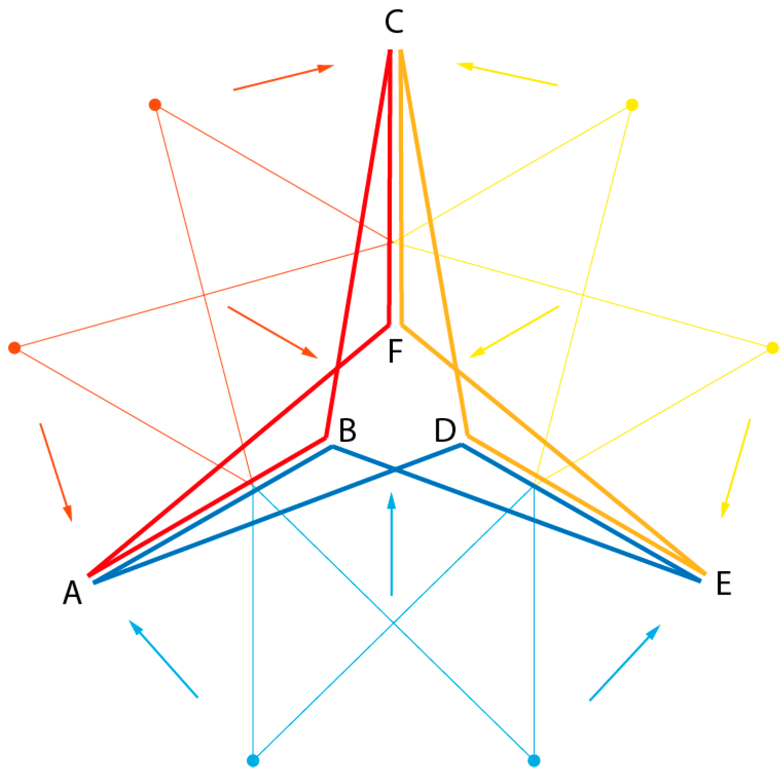
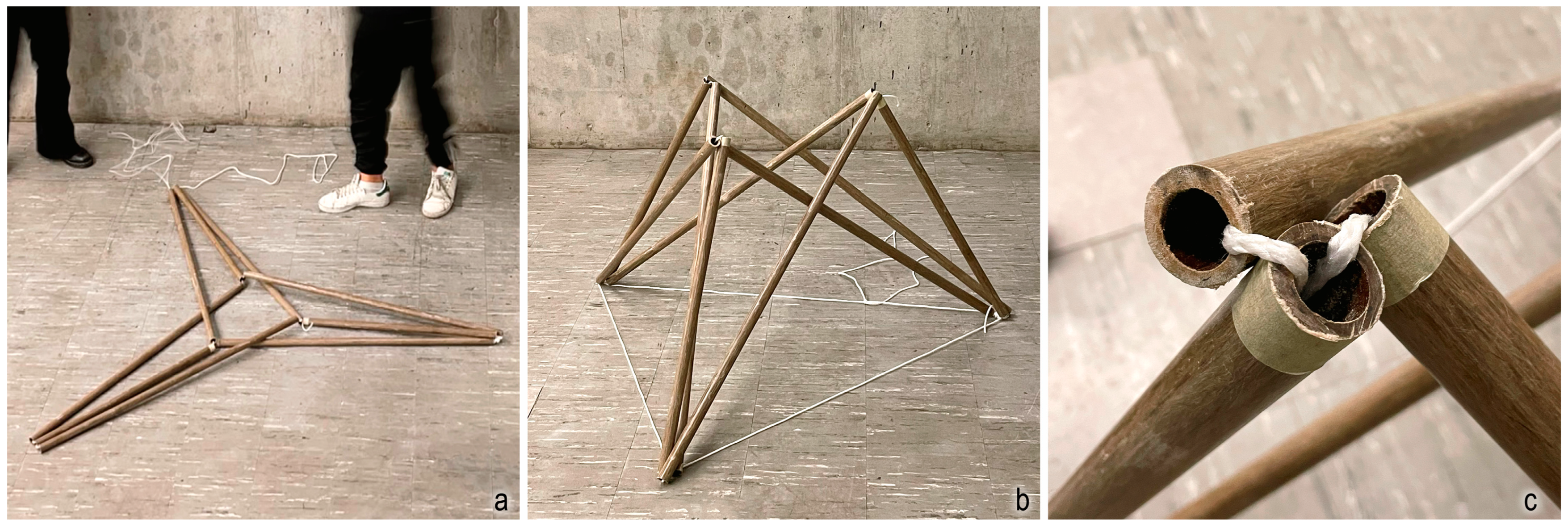
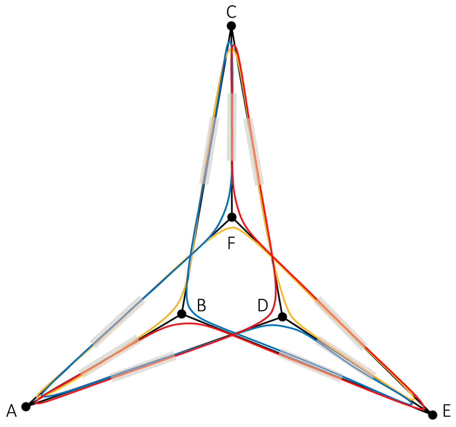
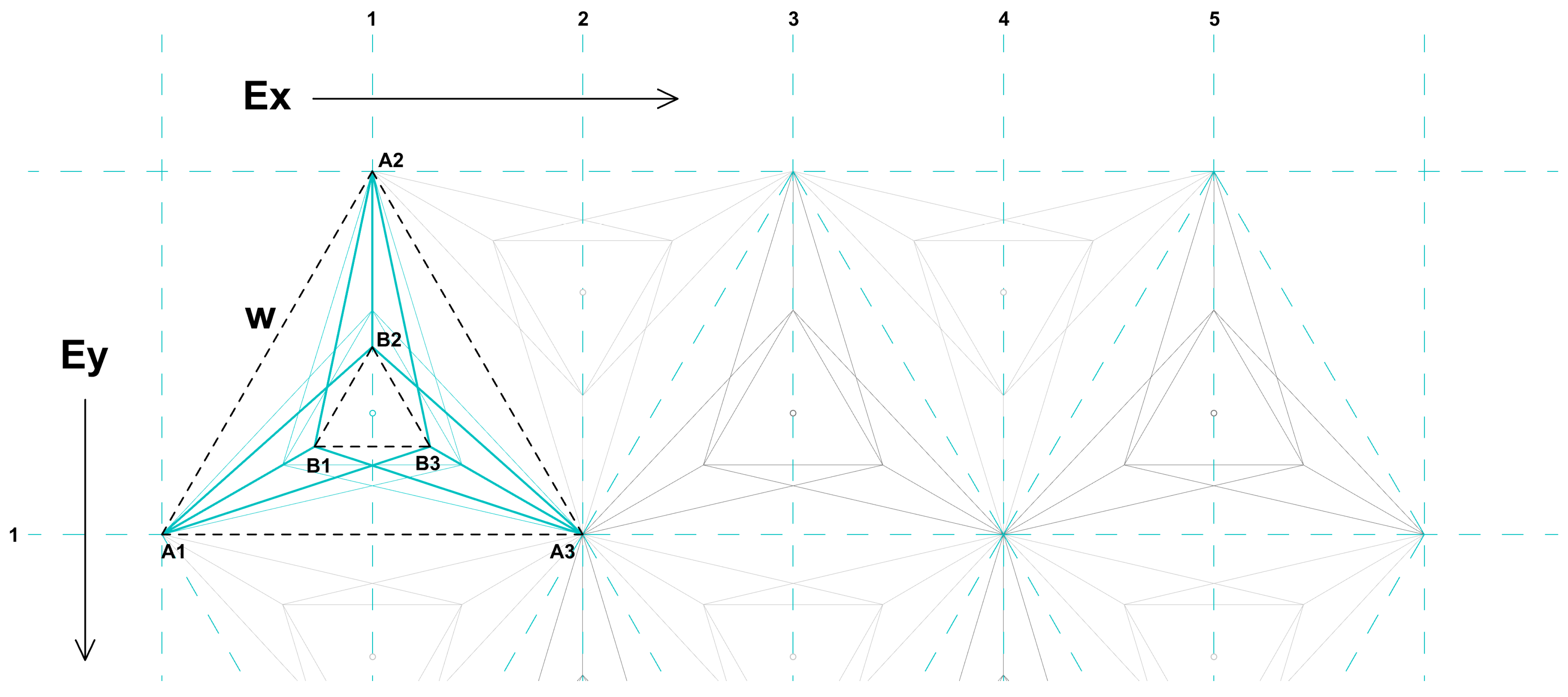
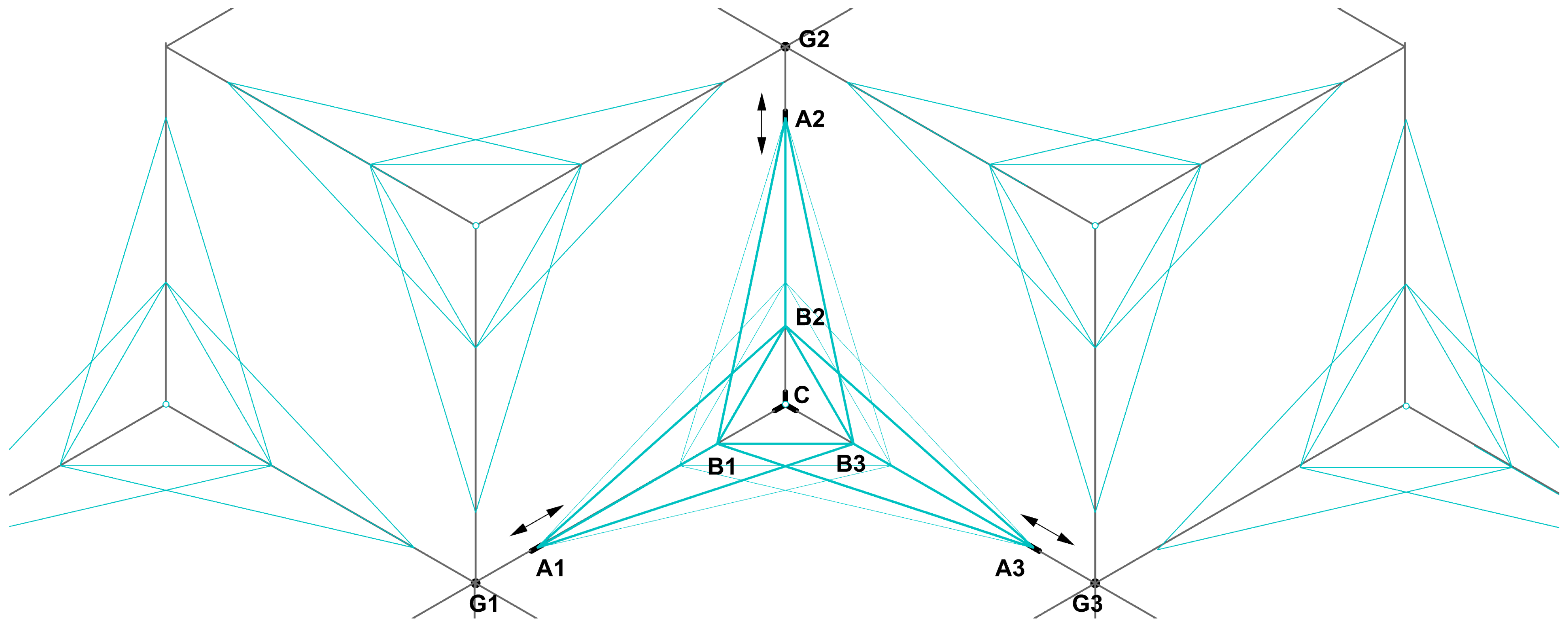
In the first phase, the core principle of the Delta IXI system, as described in the previous section, was parametrically generated using simple mathematical formulas to achieve deployability while aligning with the original design objectives. The process began with the insertion of a single point, around which an equilateral triangle was generated along with its three amplitudes. To form a spatial geometry, a second triangle was placed vertically at a defined distance from the first. Following geometric principles, nine lines were then generated, representing the structure’s primary elements. As illustrated in
Figure 17, these lines interconnect the points of the two triangles, with each point of one triangle connecting to all three points of the other. For example, A1 connects with B1, B2, and B3. Geometrically, one triangle is always smaller than the other. The parametric model relies on two main parameters: x and y. Here, x represents the amplitude length of the first triangle, while the second triangle’s amplitude length is given by y − x. The distance between the two geometries is determined by the formula: if x < (y/2), then x, otherwise (y − x). In this model, parameter y must be defined, while parameter x allows the visualisation of the deployable system’s movement.
In the second phase, the functional parametric model of the main module served as the foundation for testing various modular configurations. It was further refined for facade applications, enabling module multiplication to adapt to customised facade dimensions and enhance shading efficiency. Additional components for the supporting grid and shading elements were integrated, resulting in a fully functional system. The parametric model incorporated three primary parameters: the triangle width (w) of the primary grid and the overall grid size, defined by the number of elements horizontally (Ex) and vertically (Ey). The grid width could be manually specified by the user or automatically adjusted based on the total facade area to ensure a tailored fit. To visually demonstrate the deployment of the facade modules, the same numerical slider used for the module’s movement (parameter x) was incorporated. This enhanced flexibility, enabling dynamic adjustment along the grid rails. The modules could either converge towards the triangle centres for effective shading or diverge towards the vertices to maximise light transmission. To aid in visualisation, a triangular shape was integrated at the top triangle, providing a clear indication of the facade’s open and closed states. This adaptability ensured a balance between shading and light permeability, addressing diverse environmental and design requirements. The initial configuration assumes that all facade modules deploy simultaneously, maintaining uniform light transmission. However, this behaviour can be adjusted, allowing modules to open or close in varied patterns to meet alternative user preferences and specific functional scenarios.
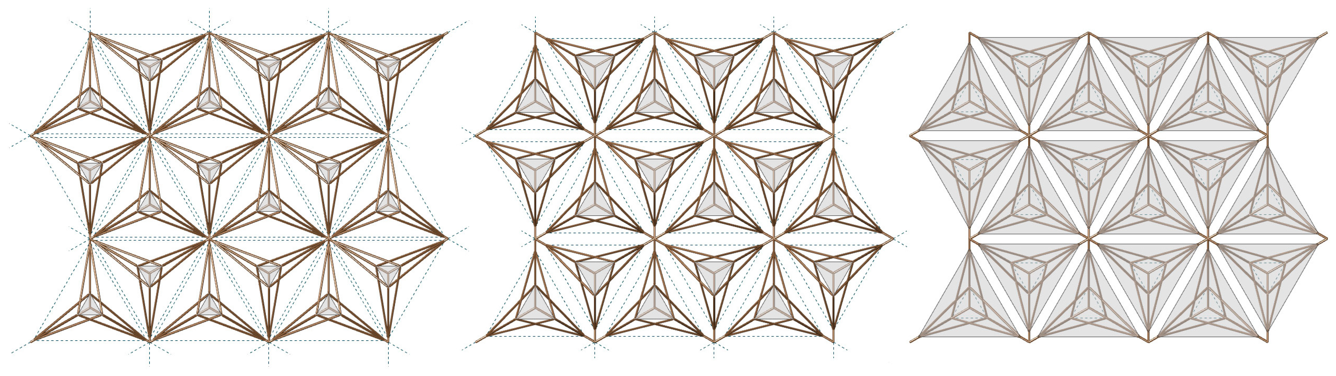
Figure 18 presents an example of a six-by-three module grid, illustrating the deployable movement of the facade and the transition between open and closed configurations. The diagram highlights how the modules shift positions, altering the facade’s permeability to light and air. The grey shape represents the shading elements, which can be stretched or retracted to modify the level of coverage. When fully extended, these elements create a continuous surface, providing complete shading, whereas in the open configuration, they retract, allowing maximum light penetration. This dynamic adaptability enables precise control over shading, accommodating varying environmental conditions and user preferences.
4.2. Concept of Shading Optimisation
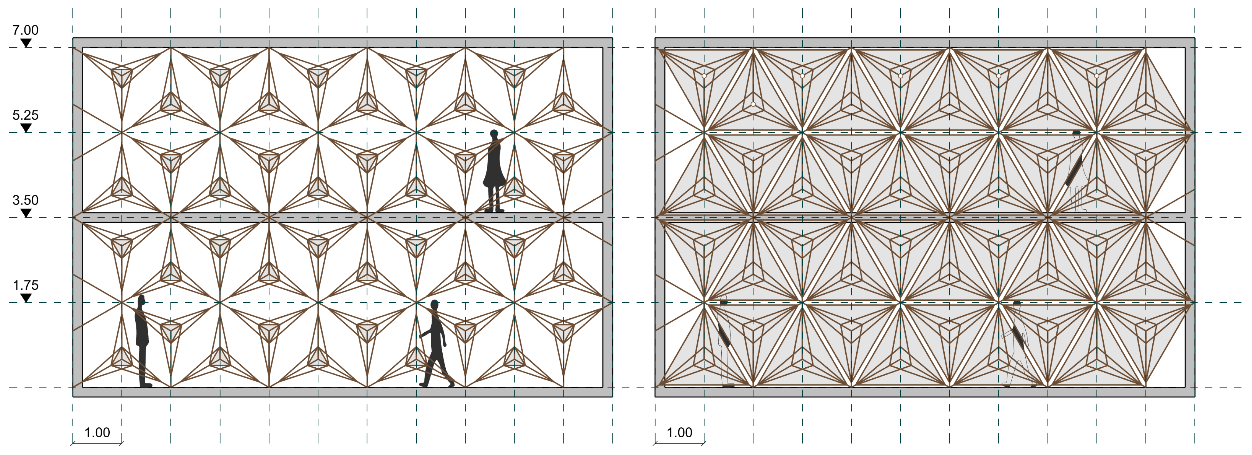
The proposed shading system introduces an adaptable solution for optimising solar exposure in building facades. Designed to respond dynamically to environmental conditions, it can efficiently regulate the amount of light entering a space, contributing to energy savings and occupant comfort. By adjusting in real-time, the system can minimise glare, improve thermal regulation, and enhance overall energy efficiency. For example, in a two-storey building, this system can adjust the facade’s shading to optimise solar gain throughout the day. The illustrated example features a grid of 1 by 1.75 m (
Figure 19), with a total building height of 7 m. The system functions as an adaptive sunshade, dynamically adjusting to control solar gain and regulate light levels, allowing for varying degrees of shading, providing up to 60–70% daylight when fully open and as low as 10–20% when closed. This adaptive feature enables the optimisation of the window-to-wall ratio (WWR) across various building orientations, as well as for different times of the day within the same orientation. As a result, it minimises direct sunlight during peak hours, reducing glare and enhancing thermal comfort by regulating interior temperatures. This, in turn, contributes to improved energy efficiency by decreasing the reliance on artificial cooling.
To further enhance adaptability, the system could integrate sensors that monitor environmental conditions, allowing for automated real-time adjustments. This capability would enhance comfort and sustainability, ensuring effective sun shading throughout the day. The flexibility of the system allows it to respond dynamically to changing conditions throughout the day, promoting a more sustainable and comfortable indoor environment. This adaptive facade could also improve the building’s aesthetic appeal, offering a contemporary, cutting-edge design element that adapts to both functional and environmental needs.
This section has outlined the overall concept of the facade, focusing on its adaptability, performance, and design potential. The following sections will delve into the technical aspects of the system, including its connection mechanisms, material selection, and fabrication processes. These elements are fundamental to translating the concept into a functional architectural solution, ensuring its durability, efficiency, and seamless integration. By examining these aspects in detail, the discussion will provide a comprehensive understanding of how the shading system operates in practice, supporting both environmental performance and design flexibility.
4.3. Concept of Materiality and Connections
One of the primary goals of this case study was to increase the structure’s bio-content. Biocomposite materials were prioritised for both the grid and connection components, aligning with sustainability goals. The supporting grid was constructed using the same biocomposite pultruded profiles, ensuring a cohesive design that expanded their application. Material exploration also focused on the nodes, where bio-based connectors were tested for their feasibility and strength in real-world applications. Finally, the shading elements required a highly stretchable textile material to accommodate the geometric transformations that occurred during deployment. This ensured that the system not only functioned effectively but also performed consistently under changing environmental conditions, meeting both aesthetic and functional objectives in the final design.
The concept of the adaptive facade required a novel approach to element connections, addressing the specific demands of a facade-scale structure. While rope threading proved effective for furniture-scale applications, the facade system necessitated more robust and durable joints. To address this, a series of connection strategies were developed, focusing on three key aspects: (1) connecting elements within the main Delta IXI module, (2) securing the module to the supporting grid, and (3) integrating and attaching the shading element.
To replace the previously used threading methods, universal joints were developed to seamlessly connect the original deployable modules, while also incorporating attachments for the railing and shading elements. Additionally, custom joints were designed and fabricated to support the grid structure, ensuring both stability and flexibility within the system. A stretchable textile material was integrated and attached to the existing joints within the framework to form the shading. As the system deployed, the textile stretched and conformed to the changing geometry, effectively achieving the desired shading effect while maintaining structural integrity.
The movement of the system is a crucial aspect of its functionality, defining how each module operates within the broader facade structure. This movement is directly linked to the design and fabrication of the connections, which were specifically developed to facilitate the system’s dynamic operation. The system includes four main types of connectors, as illustrated in
Figure 20. The system’s movement was initially defined at a module level. For the facade system, with the integration of the grid, movement commenced at the three vertices where the grid intersected the main facade (A1–3). To facilitate this movement, the three vertices must slide along their respective rails (R1–3) at an equal speed and in the same direction, converging at the central point (C1). To achieve this synchronised motion, an electronic kinetic system was developed, with the central point (C1) serving as the control hub for initiating movement, driving the mechanism along the rails (R1–3), and extending to the endpoints (A1–3). The connectors (points A) travelled along the rails through actuation, either converging towards the centre or diverging back towards the ends (points G).
4.4. Kinetic System for the Adaptive Facade
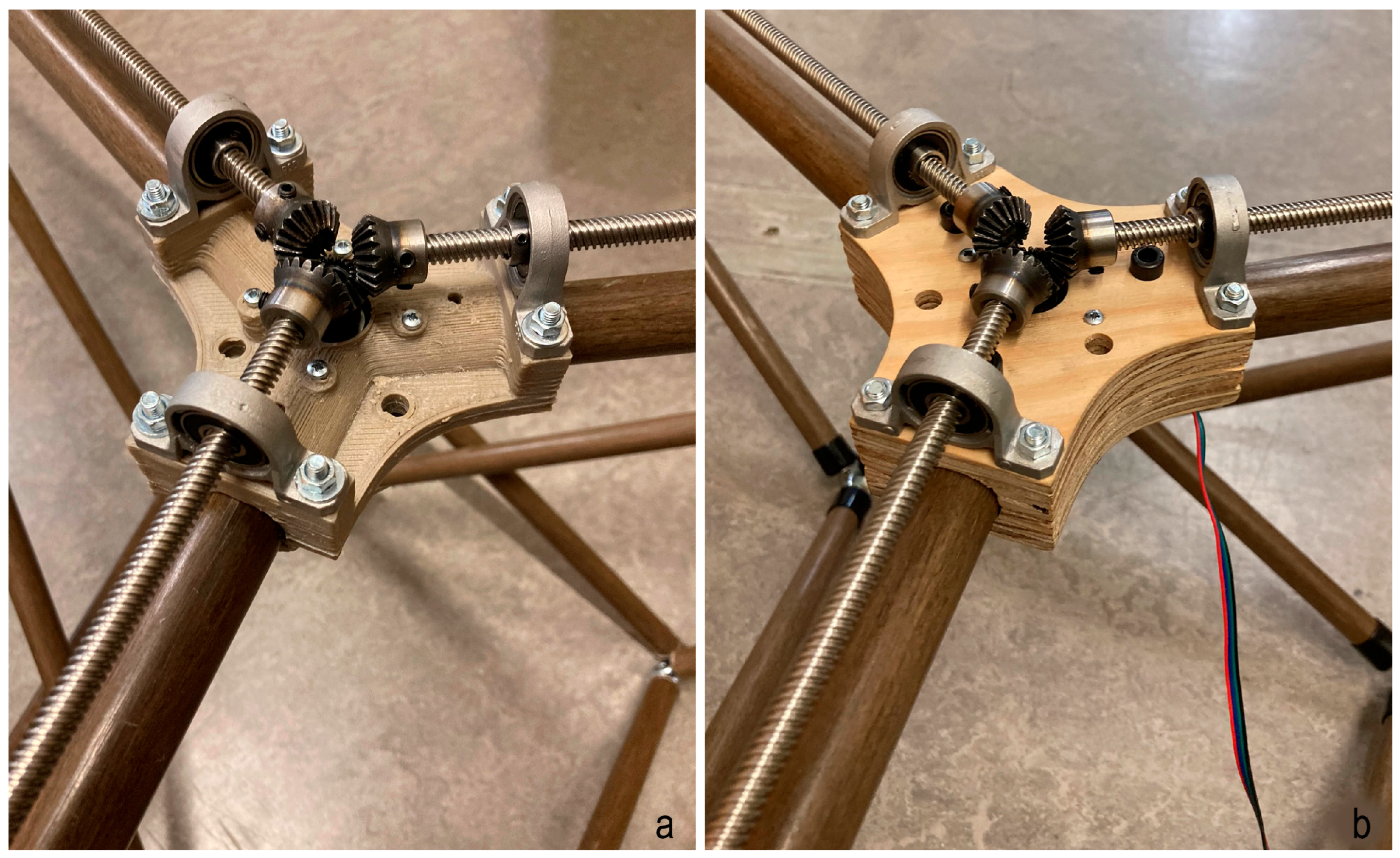
The developed kinetic system was powered by a motor-driven mechanism controlling movement along the rails. A central connector at the system’s core lies at the module’s centre (C), where the three rails (geometrically the three amplitudes of the base triangle) converge. This connector initially joined the three profiles meeting at the centre, which were part of the support grid and, at the same time, the rails of the system. It also housed a single servo motor, coordinating the overall motion. The motor was mounted on one side of this connector, transmitting rotation at a 90-degree angle to the rails via a bevel gear system mounted on the back side of the connector. The gear mechanism consisted of a central gear equipped with three surrounding pinion gears, each connected to a T8 threaded steel spindle extending along the three rail profiles. As the spindles rotated, three sliders moved parallel along the pultruded profiles, functioning like standard linear actuators, either towards the centre or reverse. These rods were supported by cylindrical bearing holders with bearings to ensure smooth rotation and alignment. The holders and the entire mechanism were secured by bolts and mounted on a customised base for precise alignment. During the prototyping phase, fabrication options were explored to maximise bio-content, involving 3D printing the base using bio-based filament. Additional tests with CNC-milled plywood were also tested (
Figure 21).
The threaded rods were joined to three connectors, which slid along the rails to enable the synchronised motion of the facade elements. These connectors were located at points A1–3 of the system (
Figure 22A). This second connector was 3D printed to enable the attachment of three profiles on one side while enabling attachment and railing along the grid profile. It incorporated a linear flange ball bearing, a mechanical component that ensured smooth motion and system alignment. It featured a cylindrical flange housing precision ball bearings inside, minimising friction and enabling movement along a linear shaft. To enable attachment to the pultruded profile, the utilised flange had an inner diameter of 25 mm, the same as the profile’s outer diameter. This customised connector enabled sliding along the rail, guided by the spindles. On the opposite side, it integrated a universal connection joint, to which the three profiles were attached. Three of these joints, located at one side of the module, facilitated the deployment of the entire system. Both joints were designed as clamps, made in two pieces to allow the profiles to be inserted and then clamped together and securely fastened with screws. A more straightforward connector type for point B consisted of an expansion anchor with an M10 eyelet, which fit perfectly inside the hollow profiles (
Figure 22B). The anchor was securely positioned within the profiles, while the eyelets facilitated the interconnection of the three profiles at this point, allowing for simple wrapping methods to join them.
The joints connecting the grid elements (G1–3) supported the overall structure. These connectors (G) had to be rigid and robust to ensure the system’s stability and maintain support during movement. Two connector types were designed based on their grid position: one for the central locations where six elements met and another for the edges where only three converged. A 3D model of these connectors was developed and optimised for 3D printing using bio-based filament. Finally, to protect the edges of the biocomposite profiles from friction and weathering while enhancing the aesthetic quality of the element, polyethylene (PE) cups were applied to the ends of all pultruded profiles (
Figure 22B). The hollow sections of the profiles were used to route the electrical cables along the grid, enabling the system’s operation while maintaining a clean aesthetic. These cables ran throughout the facade, ensuring a seamless connection to the power source. This integrated setup facilitated efficient movement control and supported the dynamic functionality of the facade system.
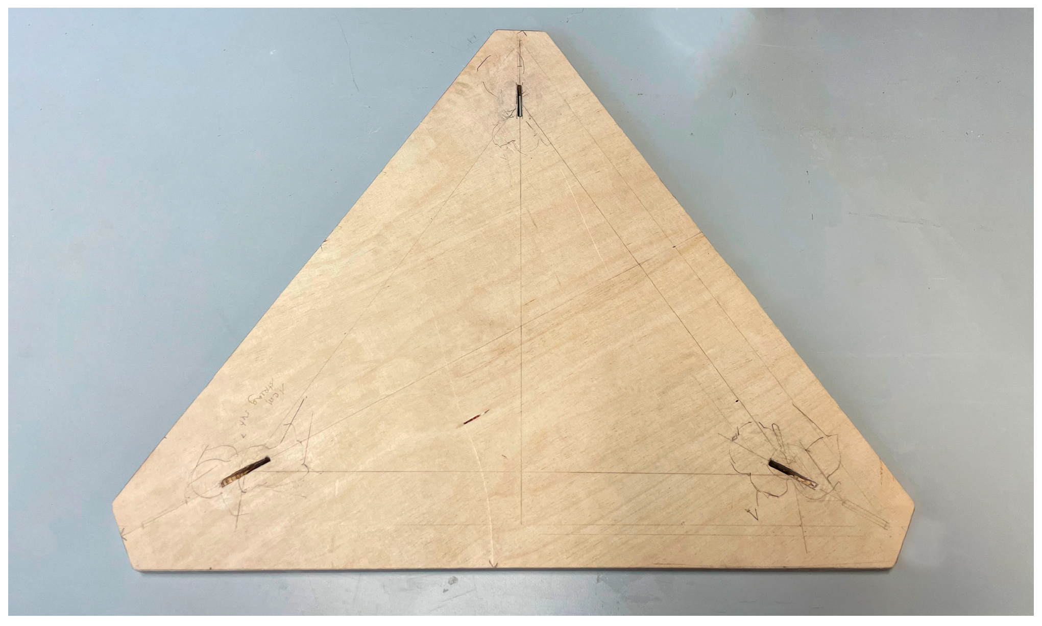
The final element of the system was the shading component, for which several options were explored. The concepts focused on integrating a stretchable textile that could provide varying levels of shading depending on the system’s deployability. These options involved attaching the textile at multiple points to offer full shading while manipulating light and shadow. The most straightforward configuration attached the textile at three outer points of the modules (B1–3), forming a triangular shape. This setup complemented the overall design, offering maximum or minimum shading. Another option involved attaching the textile at all six system points, creating more dynamic shading effects. These connections formed partial triangulations that helped maintain the textile’s tension, even in extreme positions. The textile had to be cut to the required dimensions to make the shading element, with eyelets inserted at the connection points. These eyelets allowed for easy attachment using loops around the end connections.
4.5. Built Prototype
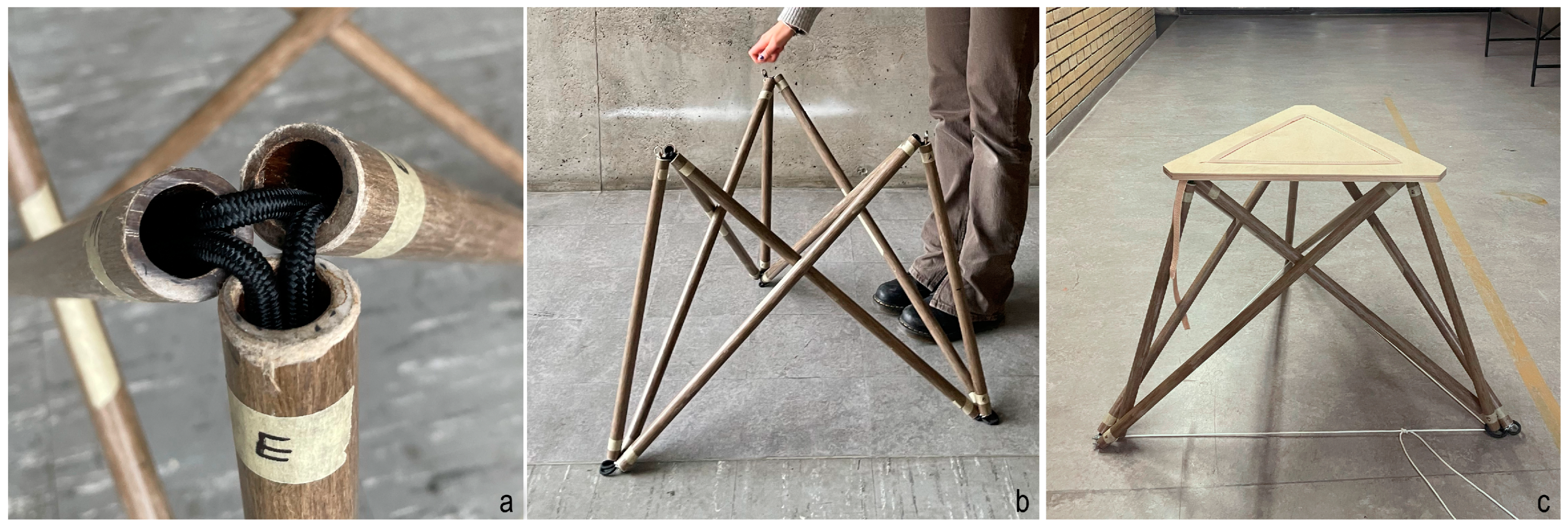
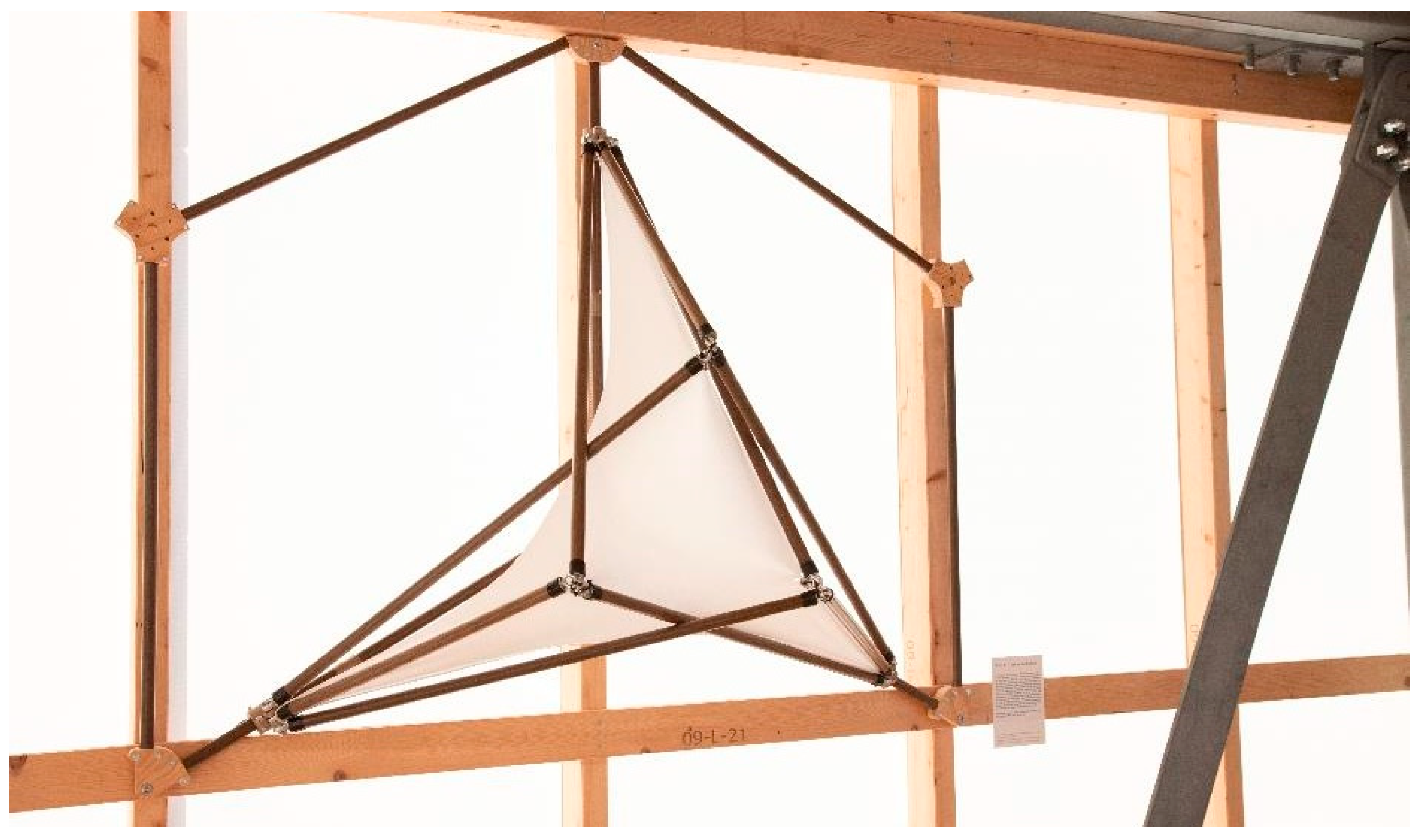
To demonstrate the implementation of the system, a single module was constructed and assembled, showcasing the developed kinetic mechanism. This module, along with part of the supporting structure, was built to a 1:1 scale, allowing for a tangible representation of the design. The grid was interconnected using precisely CNC-machined connectors, which were then mounted onto an existing timber support structure. To ensure compatibility with the given support structure, which had a spacing of 68 cm, the resulting module was designed with profile dimensions of 78 cm. The sliding connectors were 3D printed using flax fibre-reinforced PLA, adding a sustainable material choice to the design. A cotton textile was attached to all six system points to demonstrate the shading capability of the system. One module (
Figure 23) was constructed and displayed at the International Building Exhibition (Internationale BauAusstellung, IBA27) during the summer of 2023 at the ILEK Tower on the University of Stuttgart Vaihingen campus. The exhibition, “Adapt and Thrive: Biocomposites for Dynamic Architecture”, highlighted innovative approaches to architectural design, specifically focusing on the potential of biocomposites in dynamic applications. Within this exhibition, the kinetic system was integrated into the facade element, offering visitors the opportunity to observe its dynamic interactions and real-time functionalities. The display not only emphasised the aesthetic qualities of the design but also demonstrated its smooth deployability, validating both the effectiveness and the potential of the deployable system in real-world settings.
The prototype showcased here serves as a proof of concept for the deployable system, with the potential for scalability and adaptation in future implementations. This prototype was placed within an interior space, serving as a demonstration of the system’s geometry and movement, rather than being applied to an actual facade. It was designed to showcase the system’s kinetic properties and how the modules can interact dynamically. While it does not yet provide real facade functionality, the system was showcased to illustrate the possibilities of such a design. The system’s modular design allows for easy multiplication, making it adaptable for larger surfaces and complex geometries in future applications. The integration of multiple modules is seamless, thanks to the modular nature of the connectors and the system’s adaptability. Future work can expand upon this foundation, adjusting the system for more diverse architectural scales and functional requirements. The system’s flexibility not only accommodates a wide range of facades but also provides opportunities for further development in dynamic architecture, offering shading and environmental control across more complex structures.


