Abstract
Articulated heavy vehicles exhibit poor lateral stability, which may lead to unstable motion modes, e.g., trailer-sway and jackknifing, causing severe accidents. Varying relevant vehicle parameters improves the static stability but degrades the dynamic stability. The past studies focused either on the static or dynamic stability alone. However, little attention has been paid to exploring the trade-off between the static and dynamic stabilities. To gain design insights for active safety systems for AHVs, this article studies this trade-off systematically. To this end, a systematic method is proposed to conduct the linear stability and trade-off analysis. To implement and demonstrate the proposed method, a linear three-degrees-of-freedom yaw-plane model is generated to represent a tractor/semi-trailer. A trade-off analysis is conducted considering two tractor rear-axle configurations and three trailer payload arrangements. In each case, simulation is performed in both steady-state and transient testing maneuvers. To validate the linear stability analysis based on the linear yaw-plane model, two nonlinear TruckSim models are introduced, and the corresponding simulation is conducted. Insightful understanding of the trade-off is gained through analyzing the simulation results, and the linear stability analysis will provide valuable guidelines for the design and development of active safety systems for AHVs.
1. Introduction
Articulated heavy vehicles (AHVs) play a vital role in freight transportation in the world [1]. An AHV is a multi-unit vehicle combination, consisting of a towing unit, known as tractor, and one or more towed unit(s), termed trailer(s); adjacent vehicle units are connected via a mechanical coupling, e.g., fifth wheel, pintle hitch, or dolly. The wide application of AHVs is attributed to the benefits: vehicle units’ coupling and decoupling flexibility, high fuel economy, less greenhouse gas emissions, and low shipping costs [2]. Despite the above benefits, AHVs exhibit severe motion instabilities, which frequently cause fatal traffic accidents. Almost 1.19 million persons lost their lives in 2021 due to traffic accidents [3]. A huge number of fatal accidents are witnessed, in which AHVs are involved [4]. AHVs’ multiple-vehicle-unit configurations, big sizes, and high centers of gravity (CGs) make these large vehicles more prone to unstable motions, and various accidents happen owing to their poor lateral stability.
AHVs experience a 7.5-times-higher risk for fatal road accidents than single-unit vehicles, e.g., passenger vars and rigid trucks, in highway operations [5]. AHVs feature unique dynamic characteristics when compared with SUVs. With respect to an SUV, the steady-state handling performance of an articulated vehicle degrades due to the adverse impact from the trailer in dynamics and kinematics [6]. With the additional payload on the tractor via the fifth wheel from the trailer, the AHV’s static stability in the context of the steady-state handling performance may change from its original understeer to oversteer [7]. Unlike SUVs, for which the static or divergent instability associated with oversteer is the only yaw-plane instability, AHVs may experience the dynamic or oscillatory instability in addition to the static instability. For AHVs, the static (or divergent) instability refers to an aperiodic divergence of yaw motion at a vehicle forward-speed above its ‘static’ critical-speed [8]. As shown in Figure 1b,c, the severe accident of jackknifing for a tractor/semi-trailer may occur due to the aperiodic divergence of ‘tractor-swing’ or ‘trailer-swing’, respectively. As seen in Figure 1a, the dynamic instability of the tractor/semi-trailer generally manifests in an oscillatory yaw response with increasing amplitude, known as trailer-sway/snaking [9,10,11]. To increase the safety of AHVs, the effective design and control of these static and dynamic stabilities, as well as their interrelation, are critical [12,13,14].
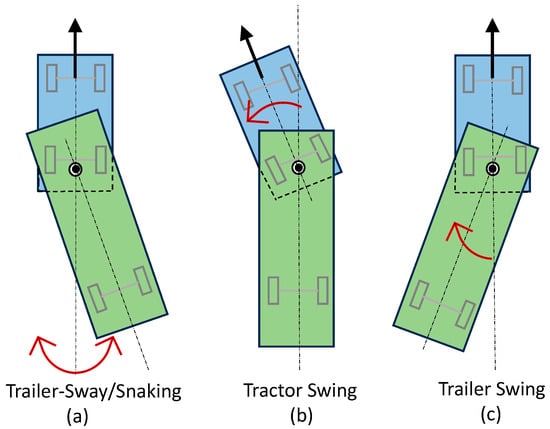
Figure 1.
Three unstable yaw-motion modes of a tractor/semi-trailer: (a) trailer-sway/snaking; (b) tractor swing; and (c) trailer swing.
The steady-state handling performance of AHVs has been long- and well-studied [15,16,17,18,19,20]. For the tractor/semi-trailer seen in Figure 1, the understeer gradient of the leading unit (i.e., tractor), , can be derived using a simplified linear yaw-plane model [7]. To ensure the static stability of the tractor, must be positive. Even though characterizes the steady-state handling behavior of the tractor, this indicator does not consider the steady-state characteristics of the trailer. To address this issue, an additional indicator, i.e., articulation angle gain, , is added, where is the articulation angle between the tractor and trailer, and the tractor front-wheel steer angle [15]. With the derivation of the steady-state articulation angle gain, the understeer gradient of the trailing unit (i.e., trailer), , can be attained. Given the understeer gradients, and , the steady-state motions of the tractor/semi-trailer can be categorized into the following three cases [7]:
- (1)
- If the leading unit is understeer, that is, , the tractor/semi-trailer is stable regardless of whether the trailing unit is understeer or oversteer;
- (2)
- If the extent of trailer oversteer is relatively larger than its counterpart of the tractor, the tractor/semi-trailer is unstable when the forward-speed approaches the respective critical-speed, leading to jackknifing in ‘trailer-swing’, as shown in Figure 1c;
- (3)
- If the tractor is oversteer and the extent of tractor oversteer is relatively larger than its counterpart of the trailer, the tractor/semi-trailer is unstable when the forward-speed approaches the corresponding critical-speed, leading to jackknifing in ‘tractor-swing’, as seen in Figure 1b.
In summary, once the tractor is understeer, the tractor/semi-trailer is statically stable; otherwise, if the tractor is oversteer, the AHV is statically unstable while the forward-speed is higher than the critical-speed, leading to jackknifing in either ‘tractor-swing’ or ‘trailer-swing’.
The past four decades have witnessed extensive studies on portraying, evaluating, and enhancing the lateral dynamic stability of AHVs [1,2,7,8,9,21,22,23,24,25,26,27,28,29,30,31,32,33]. As shown in Figure 1a, while securing the static stability under high-speed evasive maneuvers, the tractor/semi-trailer may experience the dynamic instability in trailer-sway/snaking [10,11]. To represent the oscillatory yaw motions in trailer-sway/snaking, the tractor/semi-trailer was modelled as a single pendulum [2,29]. The rearward amplification (RWA) and trailer yaw-damping ratio are generally used as the performance measures to evaluate the trailer-sway/snaking [1,8]. The RWA is frequently specified as the ratio of the maximum peak lateral acceleration of the rearmost trailer to that of the tractor. To excite and evaluate the oscillatory yaw motions of AHVs, four testing maneuvers were recommended [26]: (1) an open-loop single lane-change (SLC) with a single sinewave steering input; (2) a closed-loop SLC with a single sinewave lateral acceleration input; (3) a random steering input; and (4) a pulse steering input. To enhance the lateral dynamic stability, various solutions have been studied, including passive and active control systems. In the case of passive control, the coupling of lateral and vertical dynamics of articulated vehicles has been studied to increase the dynamic stability [31]; to suppress the yaw oscillations of trailing units, a friction damper was installed at the pintle pin connecting the leading and trailing units [27]. To actively control the lateral dynamic stability, active trailer steering [2] and trailer differential-braking [33] were proposed and investigated.
Limited effort has been put towards examining the interrelation between the static and dynamic instabilities of AHVs [17]. The Routh–Hurwitz criteria were used in distinguishing static and dynamic stability conditions. It was found that varying relevant parameters to avoid static instability may result in unstable oscillatory modes. Few ad hoc cases of the trade-off were identified for car–trailer combinations [6,11]. To date, however, no comprehensive and systematic studies have been conducted to investigate the trade-off between the static and dynamic instabilities of articulated vehicles and, in particular, AHVs. The objective of this paper is to gain an insightful understanding of the trade-off through numerical simulation and provide valuable guidelines for the design of active safety systems for AHVs. To this end, a systematic modelling and simulation method is proposed to effectively perform the trade-off analysis between the static and dynamic stabilities. To implement and demonstrate the proposed method, a linear yaw-plane model is generated to represent a tractor/semi-trailer. A trade-off analysis is performed considering two tractor rear-axle configurations and three trailer payload arrangements.
The original contributions of the paper are highlighted as follows: (1) selecting effective performance measures as the static and dynamic stability indicators; (2) choosing suitable modelling and simulation approaches for assessing static and dynamic stabilities; and (3) using accurate simulation results based on high-fidelity nonlinear models to justify the linear stability trade-off analysis.
The rest of the paper is organized as follows. Section 2 introduces the proposed performance indicators for the static and dynamic stabilities, associated evaluation methods, as well as the modelling of the tractor/semi-trailer. Section 3 conducts the static stability analysis. Section 4 performs the dynamic stability analysis. In Section 5, the trade-off analysis is conducted between the static and dynamic stabilities. Finally, the conclusions are drawn in Section 6.
2. Vehicle System Modelling
To carry out the trade-off analysis between the static and dynamic stabilities of AHVs, the performance indicators are proposed, and associated evaluation methods are introduced. To demonstrate the application of the proposed method, we analyze the trade-off between the static and dynamic stabilities of a tractor/semi-trailer. To this end, a linear three-degrees-of-freedom (DOF) yaw-plane model is derived using Simulink/MATLAB to represent the tractor/semi-trailer. To validate the linear stability analysis based on the linear model, two nonlinear TruckSim models are generated, and the respective simulations and benchmark are conducted. This section introduces the linear and nonlinear vehicle models, the proposed performance indicators, and associated evaluation methods. It should be mentioned that the steady-state handling indicator, i.e., understeer gradient, is derived and defined based on the linear 3-DOF yaw-plane vehicle model [11,15]. In this research, the linear 3-DOF yaw-plane model is used to derive this indicator. In addition, this linear vehicle model is employed for an eigenvalue analysis to determine the dynamic stability indicator, i.e., critical-speed. To justify the simulation results based on the linear yaw-plane model, the corresponding simulation results from the high-fidelity model, i.e., the TruckSim model, are also presented.
2.1. Linear 3-DOF Yaw-Plane Model
Figure 2 illustrates the linear 3-DOF yaw-plane model to portray the lateral dynamics of the tractor/semi-trailer. The linear model assumes the following: (1) each axle of the two vehicle units is represented by a single wheel situated at the center of the corresponding axle; (2) the aerodynamic drag as well as the motions of pitch, roll, and lift are ignored; and (3) the vehicle unit’s mass is lumped at its CG with a given mass moment of inertia around the corresponding vertical axis of the body-fixed reference frame. In the linear model, the motions considered comprise the lateral and yaw motions of the tractor, as well as the yaw motion of the trailer. Three reference frames are used: (1) the global coordinate system, , (2) tractor body-fixed reference frame with the origin situated at its CG, , and (3) trailer body-fixed reference frame with the origin situated at its CG, .
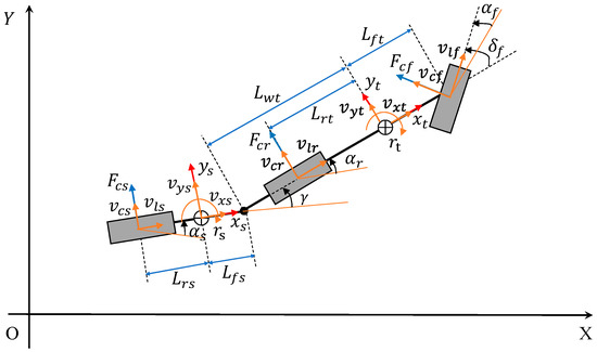
Figure 2.
Linear 3-DOF yaw-plane tractor/semi-trailer model.
According to Newton’s law of dynamics, the governing equations of motion are derived. The governing equations of the lateral and yaw motions of the tractor expressed in the tractor-fixed reference frame are expressed as follows:
where represents the mass of the tractor, represents the yaw moment of inertia of the tractor, represents the tractor yaw-rate, represents the distance from the tractor CG to the fifth wheel, represents the yaw moment due to tractor tire forces, and denote longitudinal and lateral velocities at tractor CG, is the total tractor tire forces in the lateral direction, and and are the reaction forces at the fifth wheel in the longitudinal and lateral direction.
The equations of motion of the trailer expressed in the tractor-fixed reference frame are described as follows:
where denotes the mass of the trailer, the yaw moment of inertia of the trailer, the trailer yaw moment due to its tire forces, the articulation angle between the vehicle units, the distance from the fifth wheel to the trailer CG, the yaw-rate of the trailer, and the total trailer lateral tire forces expressed in the tractor-fixed reference frame.
Combining Equations (1)–(4) and eliminating the reaction forces at the fifth wheel results in the following equations of motion of the AHV, described in the tractor-fixed reference frame as follows:
The lateral tire forces and moments can be calculated as follows:
The tire side slip angles for the vehicle wheels can be calculated as follows:
where represents the steer angle of the tractor front wheel, , , and are the side slip angle of the tractor front tire, tractor rear tire, and trailer tire, accordingly, denotes the lateral velocity of the tractor front tire, the lateral velocity of the tractor rear tire, the lateral velocity of the trailer tire, the longitudinal velocity of the tractor front tire, the longitudinal velocity of the tractor rear tire, and the longitudinal velocity of the trailer tire.
The lateral force of each tire is assumed to be proportional to its slip angle as follows:
where , are the cornering stiffnesses of the tractor front, tractor rear, and trailer tires, correspondingly. Using the above equations, the linear 3-DOF tractor/semi-trailer model is expressed in the compact form as follows:
where matrices M, D, and E are provided in the Appendix A, and the state variable vector (x) and control variable vector (u) are defined by the following:
Based on Equations (18)–(20), the linear 3-DOF tractor/semi-trailer model is generated in Simulink/MATLAB.
2.2. Nonlinear Three-Dimensional TruckSim Models
The nonlinear three-dimensional (3-D) tractor/semi-trailer models are generated with TruckSim software, which employs a multibody program, VehicleSim (VS) Lisp, to derive equations of motion [34]. Figure 3 shows the two TruckSim models with the configurations of S_S+SSS and S_SS+SSS, where S denotes a solid axle, an underline (_) a separation of axle groups, and a plus sign (+) a fifth wheel connecting two vehicle units. These nonlinear 3-D TruckSim models assume the nonlinear dynamics of suspensions, tires, and mechanical joints. The models consist of rigid bodies for the sprung-masses of the tractor and semi-trailer, as well as five or six axles. Each rigid body is allowed to move longitudinally, laterally, and vertically, as well as to rotate in roll, pitch, and yaw. The fifth wheel is represented as a ball-joint, around which roll, yaw, and pitch motions are permitted. Each axle is treated as a beam, which may roll and bounce with respect to the sprung-mass to which it is attached. Each wheel is modelled with a rotating DOF. Using TruckSim, we thus model the tractor/semi-trailer with the configurations of S_S+SSS and S_SS+SSS as a 29- and 33-DOF nonlinear model, respectively.
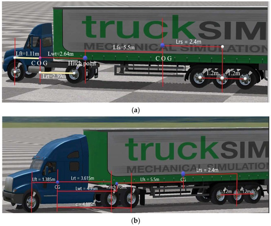
Figure 3.
Two nonlinear 3-D TruckSim models for tractor/semi-trailer with the configurations as follows: (a) S_S+SSS (tractor with single rear-axle); and (b) S_SS+SSS (tractor with double rear-axles).
The software was built upon the multibody program, vs. Lisp, for deriving equations of motion for 3-D vehicle models. An input to the vs. Lisp describes a 3-D model structure mostly in geometric terms, e.g., sprung-mass DOF, point locations, and directions of forces. Given the input, the vs. Lisp generates equations of motion in ordinary differential equations and develops a computer source code to solve them. The software comprises three main components, i.e., vs. browser, TruckSim databases, and vs. solver. The vs. browser serves as a graphical user interface to TruckSim. The browser may also be used for other applications, e.g., incorporating a controller devised using MATLAB/Simulink into the TruckSim model via the interface for co-simulation. The vs. solver is employed to solve the governing equations of motion of the model and to execute the defined simulations.
2.3. Performance Indicators for Evaluating Static and Dynamic Stabilities of AHVs
As introduced in Section 1, for a tractor/semi-trailer, if the tractor is understeer, i.e., , the AHV is statically stable; otherwise, if , the AHV is statically unstable once the vehicle forward-speed approaches the critical-speed, leading to jackknifing in either ‘tractor-swing’ or ‘trailer-swing’. Thus, the understeer gradient of the tractor, , is used as the indicator for evaluating the static stability of the AHV. To assess the lateral dynamic stability of AHVs, both the RWA and yaw-damping ratio have been used as the performance indicators. As indicated in the introduction, ISO-14791 recommends four testing maneuvers to acquire the performance indicators for assessing the dynamic stability [26]. The first three tests by ISO-14791 are designed to acquire the RWA measures, while the fourth one is used to evaluate the yaw-damping ratio. To acquire the RWA measures, both the time-response testing methods and frequency-response measuring technique have been applied [8]. The time-response testing methods can effectively acquire a specified RWA measure; however, the resulting indicator is steering-input-frequency- and forward-speed-dependent [8]. While the frequency-response measuring technique can provide a comprehensive picture for portraying the variation of the RWA within the frequency range of interest, the measuring technique is still vehicle-forward-speed-dependent [32]. The eigenvalue analysis method is effective for determining the yaw-damping ratio of an articulated vehicle, and this technique can provide a comprehensive picture depicting the variation of the performance indicator with the vehicle forward-speed [9,28]. In addition, the yaw-damping ratio and the RWA are correlated [8]. Therefore, the eigenvalue-analysis-based yaw-damping ratio is chosen as the indicator for assessing the dynamic stability of the AHV. In the subsections, the indicators for evaluating the static and dynamic stabilities are detailed, and the associated acquiring methods are introduced.
2.3.1. Understeer Gradient for Assessing Static Stability
The understeer gradient of the AHV is derived using the approach reported in [11]. Considering the steady-state motions of the tractor alone, we can determine the yaw-rate gain of the SUV, which is calculated by the following:
where denotes the state-state yaw-rate of the tractor alone, denotes the vehicle forward-speed, the wheelbase of the tractor is given by , and the understeer graduate is determined by the following:
where and denote the static loads on the front and rear tires of the tractor, correspondingly, and denotes the gravity acceleration.
Considering the steady-state motions of the AHV, we can specify the yaw-rate gain of the leading vehicle unit, which is determined by the following:
where is the variation of the understeer gradient owing to the attached semi-trailer, which can be calculated by the following:
The load shift of the trailer towards the tractor front and rear axles can be calculated by the following:
The understeer gradient of the leading unit of the AHV is given by the following:
where
The above understeer gradient () is mainly used to assess the steady-state handling performance of the AHV. To compensate this simplified evaluation, the handling diagram of the leading vehicle unit in terms of the lateral acceleration and steering angle is also used [35,36]. For validating the linear static stability analysis, the steady-state circular driving tests by ISO-14792 are simulated using the nonlinear 3-D TruckSim model [37,38], and the relevant benchmark will be conducted.
2.3.2. Eigenvalue-Analysis-Based Yaw-Damping Ratio for Evaluating Dynamic Stability
According to Equation (18), the system matrix of the linear 3-DOF yaw-plane AHV model can be determined by the following:
where matrices and are provided in Appendix A. It is found that the system matrix, , is dependent on vehicle system parameters, including tire cornering stiffnesses, and inertial and geometric parameters.
The eigenvalues of can be as follows [9,28]: (1) real numbers, , i = 1, 2, …, M, where i denotes the i-th real eigenvalues, and M the total number of real eigenvalues; and/or (2) complex numbers, that is,
where and represent the real and imaginary part of the complex eigenvalue pair, respectively, j represents the j-th pair of complex eigenvalues, and N the total number of pairs of complex eigenvalues. In the former case, the linear system experiences steady-state motions; if the real number is negative, i.e., , the system is statically stable, while, if the real number is positive, that is, , the system is statically unstable. In the latter case, the linear system exhibits dynamic motions, which are oscillations in nature; if the real part of the complex eigenvalue pair is negative, i.e., , the vehicle is dynamically stable, whereas, if the real part is positive, that is, , the vehicle is dynamically unstable. Obviously, like the Routh–Hurwitz criteria used in distinguishing static and dynamic stability conditions for AHVs [14], the above eigenvalue analysis can be applied to a tractor/semi-trailer design to identify if the resulting AHV is statically or dynamically stable. On top of the above identification functionality, the eigenvalue analysis can be used to explore the motion modes of the AHV.
In the case of the system matrix, A, for which a pair of complex eigenvalues is represented in Equation (31), the respective damping ratio can be determined by the following:
where a negative damping ratio, i.e., , indicates an unstable oscillatory motion mode. As shown in Figure 1a, for the AHV with the yaw-motion mode of trailer-sway, the indicator expressed in Equation (32) is the yaw-damping ratio, which will be used to assess the lateral dynamic stability of the AHV.
To validate and compensate the eigenvalue analysis method for assessing the lateral dynamic stability of the AHV, the open-loop SLC maneuver will be simulated using the nonlinear 3-D TruckSim models.
2.4. Tractor/Semi-Trailer Design Cases
To comprehensively evaluate the static and dynamic stabilities of the AHV, two tractor rear-axle configurations and three trailer payload arrangements are considered. Figure 3a,b show the two nonlinear 3-D TruckSim models with a tractor with a single rear-axle and a tandem-axle group, respectively. Accordingly, Figure 4a,b illustrate the top views of the tractor with the two different rear-axle configurations. The two rear-axle configurations of the tractor will provide two distinct design cases, which feature a significant difference in the total rear tire cornering stiffness. It is expected that the difference in the tractor rear tire concerning stiffness will be reflected in the static and dynamic stabilities of the two design cases.
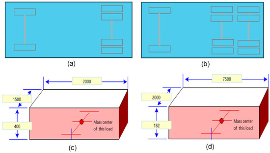
Figure 4.
Tractor/semi-trailer design cases: (a) tractor with single rear-axle; (b) tractor with rear tandem-axle group; (c) dimensions (in mm) of 9000 kg trailer payload; and (d) dimensions (in mm) of 20,000 kg trailer payload.
The three trailer payload arrangements are as follows: (1) zero payload; (2) 9000 kg payload, and (3) 20,000 kg payload. Zero payload means that the semi-trailer features its curb weight. The second and third arrangements imply that the gross trailer weight is the curb weight plus the payload of 9000 and 20,000 kg, respectively. Figure 4c,d show the dimensions of the trailer payload arrangement of 9000 and 20,000 kg, respectively. For both the trailer payload arrangements, the payload material is stainless steel with a density of 7500 kg/m3. For simplicity, the positions of the trailer CGs with the two payload arrangements are assumed to be the same as that of the zero payload one. The mass moments of inertia of these payloads are calculated based on this assumption.
In the case of the curb trailer weight and the two tractor rear-axle configurations, Table 1 provides the values for the vehicle system parameters. For the two tractor rear-axle configurations and three trailer payload arrangements, the maximum gross limit of each axle is considered [39]. Note that, as seen in Figure 3, the geometric parameters and their values listed in Table 1 are also visualized.

Table 1.
Values of vehicle system parameters for the two rear-axle group configurations with curb trailer weight.
In the following static and dynamic stability analyses for the AHV, the two tractor rear-axle configurations can be combined with the three trailer payload arrangements to form six design cases. To facilitate the static and dynamic stability analyses, these design cases are designated. For the AHV with the single tractor rear-axle configuration, the trailer payload arrangements of zero payload, 9000 kg payload, and 20,000 kg payload are termed design cases 1, 2, and 3, respectively, while, for the AHV with the double tractor rear-axle structure, the trailer payload arrangements of zero payload, 9000 kg payload, and 20,000 kg payload are named design cases 4, 5, and 6, accordingly.
3. Static Stability Evaluation
This section evaluates the static stability of the AHV using the understeer gradient of the leading vehicle unit, . To validate this assessment, the handling diagram approach is then implemented using the nonlinear 3-D TruckSim models.
3.1. Static Stability Assessment Using
Table 2 lists the values of the understeer gradient of the leading vehicle unit, , for the six design cases. A heavier trailer payload leads to a larger load shift towards the rear-axle group of the trailer, thereby decreasing the understeer gradient of the leading vehicle unit, .

Table 2.
values for different tractor/semi-trailer design cases.
A comparison between the understeer gradient coefficient values of the single tractor rear-axle configuration and the double tractor rear-axle structure clearly indicates that adding one more tractor rear-axle increases the understeer gradient of the AHV. An additional tractor rear-axle increases the wheelbase and number of rear tires of the tractor, which improves the understeer steady-state handling response as compared to the single rear-axle tractor.
3.2. Static Stability Assessment Using Handling Diagram
The steady-state handling performance of an AHV can also be evaluated by analyzing the handling diagram, which portrays the relation of the leading vehicle unit lateral acceleration with the difference between the Ackerman angle and the front wheel steer angle (L/R-) [35]. The Ackerman angle (L/R) is defined as the front wheel angle, which is required by the simplified leading vehicle unit featuring two axles with a wheelbase of L to negotiate a turn with a curve radius R at a low forward-speed, whereas the front wheel steer angle () can be determined by considering the steering-wheel angle input and the steering system gear ratio. In this method, a ramp steering-wheel input of 2 deg/s is given to the tractor/semitrailer at a constant forward-speed up to 100 km/h, which leads to the rate of change of lateral acceleration well within the range of 0.01 g/s to 0.02 g/s [35]. In this study, the steering gear ratio is set to 16.94, which is taken from the corresponding TruckSim model, and this value is used for a power assist steering system.
The handling diagram is plotted for the single and double tractor rear-axle arrangements with different trailer payload schemes to assess the steady-state handling behavior of the AHV.
Figure 5 shows the handling diagram of the single tractor rear-axle arrangement with the three trailer payloads schemes of 0, 9000, and 20,000 kg. It can be observed that the understeer gradient is dropping with the increase in trailer payload. The tractor/semi-trailer with zero trailer payload is showing an understeer behavior throughout the lateral acceleration range up to 0.35 g, whereas the understeer behaviors for the scheme of 9000 and 20,000 kg trailer payload are changing from understeer to oversteer at point A and point B, respectively. The lateral acceleration values at point A and B are 0.034 and 0.026 g, respectively. This implies that the AHV with the 9000 kg trailer payload exhibits better understeer behavior than the vehicle with the 20,000 kg trailer payload. A sensitivity analysis indicates that the heavier the trailer payload, the larger the lateral acceleration value at the neutral-steer point (e.g., point A or B in Figure 5).
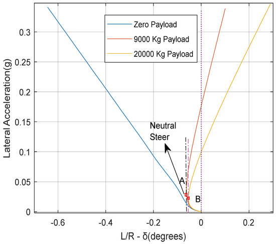
Figure 5.
Handling diagram of the tractor/semi-trailer featuring the single tractor rear-axle arrangement with different trailer payloads.
The results shown in Figure 5 through the handling diagram are consistent with the understeer gradient coefficient values listed in Table 2. However, the handling diagram seen in Figure 5 provides more detailed information regarding the steady-state handling performance of the vehicle under different operating conditions.
Figure 6 illustrates the handling diagram of the AHV featuring the double tractor rear-axle arrangement with three trailer payload schemes.
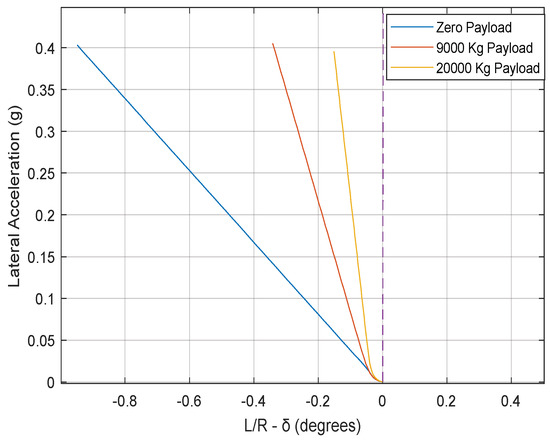
Figure 6.
Handling diagram of the AHV featuring the double tractor rear-axle arrangement with different trailer payloads.
With the increase in trailer payload, the understeer gradient decreases. This is due to the transfer of vertical trailer load towards the rear of the tractor at the fifth wheel. However, the extra rear-axle on the tractor enhances the understeer handling behavior as compared to single trailer rear-axle arrangement. The handling diagram results shown in Figure 6 agree well with the conclusion drawn from the understeer gradient coefficient values given in Table 2. It should be mentioned that, in this study, constant steering-wheel angle tests, which are similar to the steady-state circular tests by ISO-14792 [37,38], are simulated using the nonlinear 3-D TruckSim models. The results from the simulated constant steering-wheel angle tests concur with those based on the handling diagram approach.
4. Dynamic Stability Evaluation
In this section, the performance indicator in the damping ratio determined using the eigenvalue analysis method is utilized to evaluate the lateral dynamic stability of the tractor/semi-trailer. To justify and compensate this evaluation, an open-loop SLC testing maneuver is simulated using the nonlinear 3-D TruckSim models.
4.1. Dynamic Stability Assessment Using Eigenvalue Analysis
The matrix, A, expressed in Equation (30) is utilized to calculate the eigenvalues considering the single and double tractor rear-axle arrangements with three different trailer payload schemes. Provided a pair of complex eigenvalues, the damping ratio is calculated using Equation (32).
4.1.1. Eigenvalue Analysis for Single Tractor Rear-Axle Configuration
Figure 7a shows the relationship between the damping ratio and forward-speed for the single tractor rear-axle arrangement with the zero trailer payload scheme, i.e., design case 1. In this figure, the two curves represent two motion modes of the tractor/semitrailer. For the least-damped motion mode, which corresponds to the trailer-sway/snaking shown in Figure 1a, the damping ratio drops as the forward-speed increases. When the damping ratio takes the value of zero, the vehicle forward-speed is approximate 59 m/s, which is the critical-speed. Beyond the critical-speed, the tractor/semi-trailer will lose its lateral dynamic stability, experiencing trailer sway with the oscillation amplitude increasing with time. For the single tractor rear-axle arrangement with the 9000 and 20,000 kg trailer payloads, i.e., design cases 2 and 3, the respective relationships between the damping ratio and forward-speed are shown in Figure 7b,c.
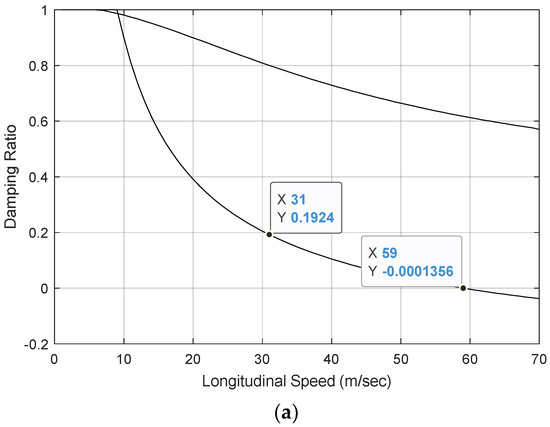
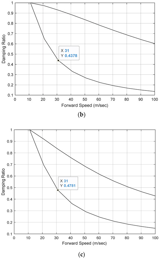
Figure 7.
Damping ratio vs. forward-speed for single tractor rear-axle arrangement with: (a) zero trailer payload (case 1); (b) 9000 kg trailer payload (case 2); and (c) 20,000 kg trailer payload (case 3).
In design case 2, for the two motion modes shown in Figure 7b, even though the damping ratio drops with the vehicle forward-speed, within the speed range concerned, the damping ratio of the least-damped motion mode remains positive. This implies that the vehicle is dynamically stable at a forward-speed of up to 100 m/s. A comparison between the results seen in Figure 7a,b discloses that increasing the trailer payload is beneficial for improving the dynamic stability of the AHV. Load added to the trailer increases the vertical tire load, which increases the trailer tire cornering forces, thereby increasing the yaw-damping effect of the AHV.
Like design case 2, as illustrated in Figure 7c, design case 3 is dynamically stable over the forward-speed range concerned. To identify the difference between the two design cases, we compare the damping ratios at the forward-speed of 31.0 m/s for the least-damped motion modes of the two cases. As seen in Figure 7b,c, at the given forward-speed, the damping ratio for case 2 is 0.4378, whereas the counterpart for case 3 is 0.4781. Thus, considering the three trailer payload schemes, for the single tractor rear-axle arrangement, we may conclude that increasing the trailer payload is beneficial for improving the lateral dynamic stability of the AHV.
4.1.2. Eigenvalue Analysis for Double Tractor Rear-Axle Configuration
Figure 8a illustrates the relationship between the damping ratio and forward velocity for the double tractor rear-axle arrangement with the zero trailer payload, that is, design case 4. It is found that, for the two motion modes, the damping ratio drops with the increase in forward-speed. For the least-damped mode, at the speed of 72 m/s, the damping ratio is zero. This means that the speed of 72 m/s is the critical-speed, above which the vehicle will lose its lateral dynamic stability. For the trailer payloads of 9000 and 20,000 kg, i.e., design cases 5 and 6, the corresponding relationships between the damping ratio and forward-speed are illustrated in Figure 8b and Figure 8c, respectively.
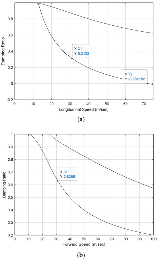
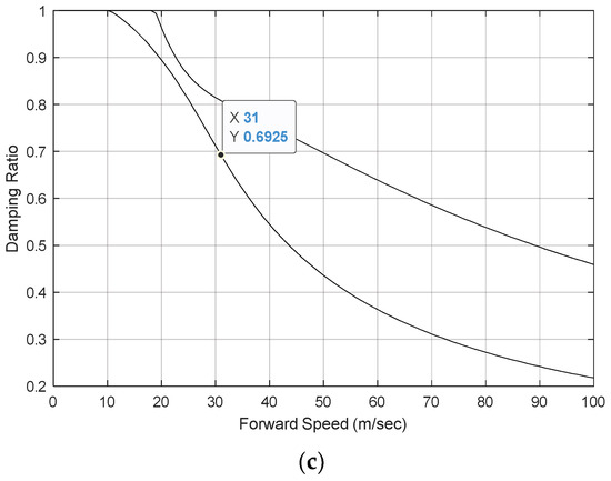
Figure 8.
Damping ratio vs. forward-speed for double tractor rear-axle arrangement with (a) zero trailer payload (case 4); (b) 9000 kg trailer payload (case 5); and (c) 20,000 kg trailer payload (case 6).
Like case 4, for both cases 5 and 6, the damping ratios of the two motion modes drop with the increase in forward-speed. However, unlike case 4, for both cases 5 and 6, within the given speed range, the damping ratio of the least-damped motion mode remains positive, implying that the AHV is dynamically stable in the speed range shown in the figures.
To effectively evaluate the effects of the two tractor rear-axle arrangements and the three trailer payload schemes on the dynamic stability of the AHV, in each of Figure 7 and Figure 8, the respective damping ratio of the least-damped motion mode at the forward-speed of 31 m/s is identified. The identified damping ratios are listed in Table 3. Given the data provided in the table, the following points can be made: (1) regardless of the tractor rear-axle arrangement, the larger the trailer payload, the higher the lateral dynamic stability of the AHV; and (2) given a trailer payload, the double tractor rear-axle arrangement exhibits higher lateral dynamic stability compared against the single tractor rear-axle arrangement.

Table 3.
Damping ratios of the least-damped motion mode for different tractor/semi-trailer design cases at the forward-speed of 31 m/s.
4.2. Dynamic Stability Assessment Using Simulated Open-Loop SLC Testing Maneuver
The lateral dynamic stability of the AHV can also be evaluated under the open-loop SLC testing maneuver recommended by ISO-14791 [26]. In this study, this open-loop SLC testing maneuver is simulated using the nonlinear 3-D TruckSim models. Figure 9 illustrates the time-history of the tractor front-wheel steering angle for the simulated testing maneuver.
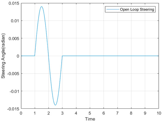
Figure 9.
Time-history of the tractor front-wheel steering angle for the open-loop SLC maneuver.
4.2.1. Simulation Results for Single Tractor Rear-Axle Configuration
As shown in Figure 7a, for the single tractor rear-axle configuration with the zero trailer payload, i.e., design case 1, the eigenvalue analysis based on the linear 3-DOF yaw-plane model identifies the critical-speed of 59.0 m/s. To justify the identified critical-speed, in the simulated SLC maneuver, two forward-speeds are selected, i.e., 50.0 and 70.0 m/s. Thus, the selected forward-speed of 50.0 m/s is less than the critical-speed, while the forward-speed of 70.0 m/s is higher than the critical-speed. Figure 10a,b show the time-history of the trailer yaw-rate for the single tractor rear-axle configuration with the three trailer payload arrangements acquired under the SLC maneuver at a forward-speed of 50.0 and 70.0 m/s, respectively.
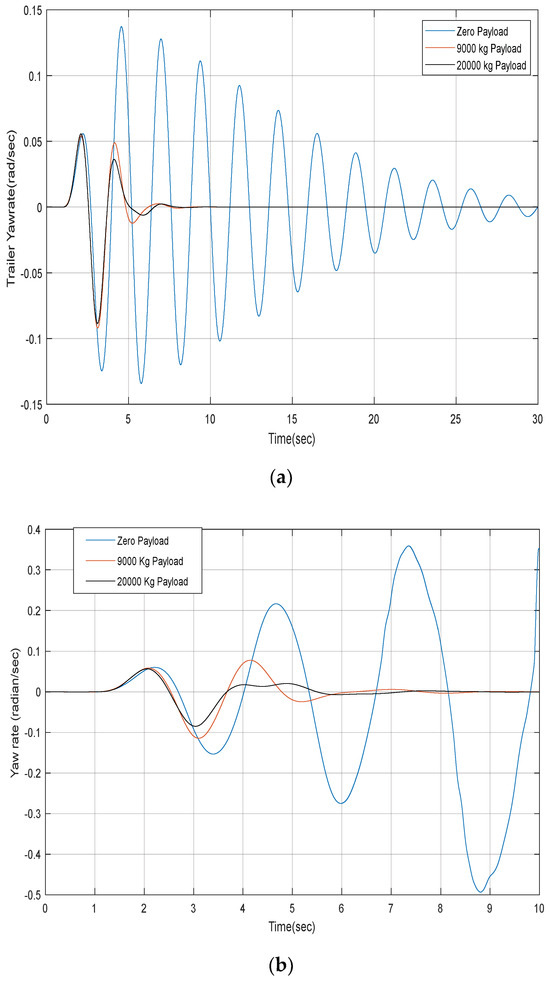
Figure 10.
Time-history of trailer yaw-rate for the single tractor rear-axle configuration with three trailer payload arrangements at forward-speed of (a) 50.0 m/s and (b) 70.0 m/s.
For design case 1, i.e., the zero trailer payload, it is expected that, over the SLC maneuver at the forward-speed of 50.0 m/s, the tractor/semi-trailer should behave in a dynamically stable manner, since the testing speed is lower than the critical-speed of 59.0 m/s, while, over the SLC maneuver at the forward-speed of 70.0 m/s, the AHV is expected to lose its yaw stability, since the testing speed is higher than the critical-speed of 59.0 m/s. As seen in Figure 10a,b, the simulation results for case 1 match the above expectation; as seen in Figure 10a, for case 1, over the SLC maneuver at 50.0 m/s, the trailer yaw-rate oscillates, with its amplitude decreasing with time, and, eventually, the AHV settles down with its steady-state motion, whereas, as illustrated in Figure 10b, for case 1, over the SLC maneuver at 70.0 m/s, the trailer yaw-rate oscillates, with its amplitude increasing with time, and, eventually, the vehicle loses its yaw stability. Thus, the simulation results based on the nonlinear 3-D TruckSim model justifies the critical-speed predicted by the eigenvalue analysis based on the linear 3-DOF yaw-plane model.
On the other hand, for the trailer payload arrangements of 9000 and 20,000 kg, i.e., design cases 2 and 3, as seen in Figure 10a,b, the trailer yaw-rate oscillates around one cycle of the sinewave, and, eventually, the AHV settles down to its stable steady-state straight line motion. It is also observed that the lighter the trailer payload is, the more violent the trailer yaw-rate oscillation becomes. Thus, the time-domain simulation based on the nonlinear 3-D TruckSim model is consistent with that of the eigenvalue analysis using the linear 3-DOF yaw-plane model.
4.2.2. Simulation Results for Double Tractor Rear-Axle Configuration
As seen in Figure 8a, for the double tractor rear-axle arrangement with the zero trailer payload, that is, design case 4, the critical-speed of 72.0 m/s is predicted by the eigenvalue analysis based on the linear 3-DOF yaw-plane model. To examine the effectiveness of this prediction, the nonlinear 3-D TruckSim model is used to simulate the open-loop SLC testing maneuver at two forward-speeds, that is, 65.0 and 80.0 m/s, between which the former is below the critical-speed of 72.0 m, while the latter is above the critical-speed. Figure 11a,b illustrate the time-history of the trailer yaw-rate for the double tractor rear-axle configuration with the three payload arrangements attained under the SLC maneuver at a forward-speed of 65.0 and 80.0 m/s, accordingly.
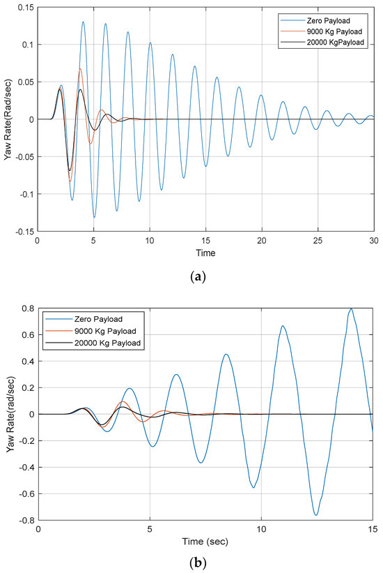
Figure 11.
Time-history of trailer yaw-rate for the double tractor rear-axle configuration with three trailer payload arrangements at forward-speed of (a) 65.0 m/s and (b) 80.0 m/s.
It is envisaged that, for design case 4 (i.e., the zero trailer payload), the tractor/semi-trailer will remain dynamically stable over the SLC maneuver at the forward-speed of 65.0 m/s, because the testing speed is below the critical-speed of 72.0 m/s, whereas, over the SLC maneuver at the forward-speed of 80.0 m/s, the AHV is anticipated to lose its yaw stability, since the testing speed is above the critical-speed of 72.0 m/s. As depicted in Figure 11a,b, the simulation results for case 4 concur with the above expectation; Figure 11a shows that, for design case 4, at a testing speed of 65.0 m/s, the trailer yaw-rate fluctuates with its amplitude damped with time, and, eventually, the AHV settles down with its steady-state motion, while, as seen in Figure 11b, for case 1, at a testing speed of 80.0 m/s, the trailer yaw-rate surges, with its amplitude increasing with time, and, eventually, the AHV loses its yaw stability. Therefore, the simulation results based on the nonlinear 3-D TruckSim model rationalize the critical-speed envisioned by the eigenvalue analysis based on the linear 3-DOF yaw-plane model.
For the trailer payload arrangements of 9000 and 20,000 kg, i.e., design cases 5 and 6, as illustrated in Figure 11a,b, over the SLC maneuver, at the testing speed of both 65.0 and 80.0 m/s, the AHV behaves dynamically stable, and the respective trailer yaw-rate fluctuates with much lower amplitudes compared against their counterparts of design case 4. Once again, it is found that the lighter the trailer payload is, the more violent the trailer yaw-rate oscillation becomes. Therefore, the time-domain simulation results based on the nonlinear 3-D TruckSim model concur with that of the eigenvalue analysis using the linear 3-DOf yaw-plane model.
5. Trade-Off Relationship between Static and Dynamic Stabilities
As introduced in Section 3 and Section 4, the performance measures listed in Table 2 and Table 3 are used for evaluating the static and dynamic stabilities of the different tractor/semi-trailer design cases, respectively. These performance measures are determined using the linear 3-DOF yaw-plane model, and they are justified by simulation results based on the nonlinear 3-D TruckSim model. Thus, these performance measures will be used to analyze the trade-off relationship between the static and dynamic stabilities of the AHV. To facilitate the analysis of the trade-off relationship between the static and dynamic stabilities of the tractor/semi-trailer, Table 2 and Table 3 are combined and the compound performance measures of the tractor/semi-trailer with different design cases are listed in Table 4. It should be mentioned that, in Table 4, the static stability indicator, , is evaluated using Equation (27) with a given tractor rear-axle arrangement and trailer payload, while the dynamic stability indicator, the damping ratio, is determined using Equation (32) with the same tractor rear-axle arrangement and trailer payload at the vehicle forward-speed of 31 m/s. Note that the static stability indicator is independent of the vehicle forward-speed.

Table 4.
values and damping ratios of the least-damped motion mode at forward-speed of 31.0 m/s for different tractor/semi-trailer design cases.
A close inspection of the data listed in Table 4 leads to the following observations:
- (1)
- Regardless of the tractor rear-axle configurations, increasing the trailer payload leads to the decrease in the understeer gradient of the leading vehicle unit, , while increasing the trailer payload results in the increase in the damping ratio at the specified speed;
- (2)
- Given a trailer payload, compared with the single tractor rear-axle configuration, the double tractor rear-axle structure not only increases the understeer gradient of the leading vehicle unit, , but also increases the damping ratio at the specified speed.
The above observations have been interpreted partially and separately in Section 3 and Section 4. To synthesize the associated key points, they are summarized as follows. Regarding the first observation, with an increase in trailer payload, it will be mainly transferred to the rear of the tractor via the fifth wheel. As expressed in Equation (27), the increased rear-axle load of the tractor, , makes the understeer gradient, , reduced. On the other hand, an added trailer payload increases the vertical forces on trailer tires, thereby leading to an increase in total lateral trailer tire force and resulting in an increased yaw-damping effect of the trailer. Thus, the trailer payload imposes a conflicting or opposite effect on the static and dynamic stabilities of the tractor/semi-trailer.
In terms of the second observation, an additional rear-axle of the tractor directly increases the total rear tire cornering stiffness of the leading unit, , which causes the understeer gradient, , to be increased, as expressed in Equation (27). As mentioned in the introduction, to analyze the trailer-sway/snaking motions shown in Figure 1a, the tractor/semi-trailer may be modelled as a single pendulum [2,29]. An extra rear-axle of the tractor causes the pivot of the pendulum to grasp on the stationary road surface more firmly. The increased road holding capability of the pendulum pivot may decrease the trailer yaw-rate oscillation, thereby enhancing the lateral dynamic stability of the AHV. Therefore, compared with the single tractor rear-axle configuration, the double tractor rear-axle structure not only increases the understeer gradient of the leading vehicle unit, , but also increases the damping ratio at the specified vehicle speed.
This study only provides limited design cases to explore the trade-off relationship between the static and dynamic stabilities of the tractor/semi-trailer. However, using the proposed method, design engineers may conduct the trade-off analysis considering a large spectrum of design cases, including different AHV types (e.g., A- and B-train doubles), various vehicle parameters (e.g., tractor and trailer wheelbases), etc.
Note that the proposed method is only used for the stability trade-off analysis for conventional AHVs without active safety systems, e.g., active steering, differential-braking, etc. For AHVs with linear-control-based active safety systems [40,41,42], the proposed methods can be directly applied. In the case of nonlinear control systems [43], the proposed method needs to be modified, and the trade-off analysis may be conducted using co-simulations based on co-simulation platforms, e.g., MATLAB/Simulink–TruckSim, where the nonlinear controller is designed using MATLAB/Simulink, the virtual AHV is fabricated in TruckSim, the controller and the virtual AHV are then integrated by the interface between the two software packages, and, finally, the co-simulation can be conducted.
It should be emphasized that the proposed method is suitable for initial vehicle designs to identify the trade-off between the static and dynamic stabilities of AHVs. In the initial vehicle designs, considering the cost and safety concerns, it may not be practical to conduct a field or road test to evaluate vehicles’ static and dynamic stabilities. Nowadays, vehicle modeling and simulation is of importance for vehicle design and development. Simulation is increasingly used in the design and testing of vehicles in a virtual environment before a real full-size vehicle prototype is built [44]. In the Australian performance-based standards for AHVs, both simulations and in-vehicle tests are permitted for assessing the lateral dynamics of these large vehicles [45]. The proposed method will be validated using experimental data to demonstrate its reliability [46]. However, the experimental validation of the proposed method is beyond the scope of the paper.
6. Conclusions
This paper proposes a systematic method to analyze the trade-off relationship between the static and dynamic stabilities of articulated heavy vehicles. The proposed method includes the key components of (1) linear and nonlinear vehicle system modelling; (2) performance indicator selections and definitions for the static and dynamic stabilities; and (3) numerical simulations based on the linear and nonlinear vehicle models for evaluating and validating the static and dynamic stabilities. The understeer gradient of the leading vehicle unit is selected as the indicator for assessing the static stability; a constant speed test is simulated to generate the handling diagram to justify and compensate the indicator-based assessment. The damping ratio based on the eigenvalue analysis is defined as the indicator for evaluating the dynamic stability; an open-loop SLC testing maneuver is simulated to validate and compensate the damping-ratio-based evaluation.
To implement and demonstrate the effectiveness of the proposed method, a linear 3-DOF yaw-plane model and a nonlinear 3-D TruckSim model are generated to represent a tractor/semi-trailer. Six design cases are constructed considering two tractor rear-axle configurations and three trailer payload arrangements. The understeer gradient of the leading vehicle unit and the damping ratio based on the eigenvalue analysis are used as the performance indicators to assess the static and dynamic stabilities, respectively. The acquired performance measures for the static and dynamic stabilities derived from the linear vehicle model are justified and compensated by the handling diagram and the simulated SLC testing maneuver based on the nonlinear TruckSim model. The analysis of the trade-off between the static and dynamic stabilities of the tractor/semi-trailer leads to the following conclusions:
- (1)
- Regardless of the tractor rear-axle configurations, increasing the trailer payload leads to the degradation of the static stability of the tractor/semi-trailer, while increasing the trailer payload is beneficial for enhancing the dynamic stability of the AHV.
- (2)
- Compared with the single tractor rear-axle configuration, the double tractor rear-axle structure not only strengthens the static stability of the AHV, but also enhances the lateral dynamic stability of the vehicle.
This paper only provides the limited design cases to explore the trade-off relationship between the static and dynamic stabilities of the tractor/semi-trailer. However, applying the proposed method, design engineers can conduct the trade-off analysis considering a large spectrum of design cases, including different AHV types, e.g., A- and/or B-train doubles, various vehicle parameters, such as tractor and/or trailer wheelbases, etc.
Author Contributions
Conceptualization and methodology, T.S. and Y.H.; writing—original draft preparation, T.S.; supervision, Y.H.; funding acquisition, Y.H. All authors have read and agreed to the published version of the manuscript.
Funding
This research was funded by the Natural Sciences and Engineering Research Council of Canada, grant number RGPIN/2019-05437.
Data Availability Statement
Data are contained in the article.
Acknowledgments
Y.H. would like to thank the team members of the Multidisciplinary Vehicle Systems Design Laboratory, University of Ontario Institute of Technology. These team members have carried out a preliminary study on evaluating the lateral dynamic stability of articulated heavy vehicles.
Conflicts of Interest
The authors declare no conflicts of interest.
Appendix A
In Equation (18), the matrices M, D, and E are expressed as follows:
where
References
- Fancher, P.S.; Winker, C.B. Directional performance issues in evaluation and design of articulated heavy vehicles. Veh. Syst. Dyn. 2007, 45, 607–647. [Google Scholar] [CrossRef]
- Roebuck, R.; Odhams, A.; Tagesson, K.; Cheng, C.; Cebon, D. Implementation of trailer steering control on a multi-unit vehicle at high speeds. J. Dyn. Syst. Meas. Control. 2014, 136, 1021016. [Google Scholar] [CrossRef]
- World Health Organization. Global Status Report on Road Safety 2023. Available online: https://iris.who.int/bitstream/handle/10665/374868/9789240086456-eng.pdf?sequence=1 (accessed on 15 August 2024).
- Grislis, A. Longer combination vehicles and road safety. Transport 2010, 25, 336–343. [Google Scholar] [CrossRef]
- European Agency for Safety and Health at Work. A Review of Accidents and Injuries to Road Transport Drivers; Publications Office of the European Union: Luxembourg, 2010; 61p, ISBN 978-92-9191-355-8. [Google Scholar]
- Kang, X.; Deng, W. Vehicle-Trailer Handling Dynamics and Stability Control—An Engineering Review; SAE Technical Paper; SAE: Troy, MI, USA, 2007; Paper No. 2007-01-0822. [Google Scholar]
- Vempaty, S.; He, Y.; Zhao, L. An overview of control schemes for improving the lateral stability of car trailer combinations. Int. J. Veh. Perform. 2020, 6, 151–199. [Google Scholar] [CrossRef]
- Zhu, S.; Ni, Z.; Rahim, A.; He, Y. On dynamic stability evaluation methods for lone combination vehicles. Veh. Syst. Dyn. 2022, 60, 3999–4034. [Google Scholar] [CrossRef]
- He, Y.; Khajepour, A.; McPhee, J.; Wang, X. Dynamic modelling and stability analysis of articulated frame steer vehicles. Int. J. Heavy Veh. Syst. 2005, 12, 28–59. [Google Scholar] [CrossRef]
- Kurtz, E.F.; Anderson, R.J. Handling characteristics of car-trailer systems: A state-of-the-art survey. Veh. Syst. Dyn. 1977, 6, 217–243. [Google Scholar] [CrossRef]
- Hac, A.; Fulk, D.; Chen, H. Stability and control considerations of vehicle-trailer combination. SAE Int. J. Passeng. Cars Mech. Syst. 2009, 1, 925–937. [Google Scholar] [CrossRef]
- Asiabar, A.N.; Gordon, T.; Gao, Y.; Henderson, L.; Laine, L. Coordinated chassis control of a tractor-semitrailer combination operating at its handling limits using the MHA methodology. Veh. Syst. Dyn. 2024, 1–26. [Google Scholar] [CrossRef]
- Amoruso, F.; Cebon, D. Brake-actuated steering control strategy for turning of articulated vehicles. Veh. Syst. Dyn. 2024, 1–31. [Google Scholar] [CrossRef]
- Sharma, T.; He, Y. Design of a tracking controller for autonomous articulated heavy vehicles using a nonlinear model predictive control technique. Proc. Inst. Mech. Eng. Part K J. Multi-Body Dyn. 2024, 238, 334–362. [Google Scholar] [CrossRef]
- Wong, J.Y. Theory of Ground Vehicles, 4th ed.; John Wiley & Son, Inc.: Hoboken, NJ, USA, 2008. [Google Scholar]
- Winkler, C.B. Simplified analysis of the steady-state turning of complex vehicles. Veh. Syst. Dyn. 1998, 29, 141–180. [Google Scholar] [CrossRef]
- Fancher, P.S. The static stability of articulated commercial vehicles. Veh. Syst. Dyn. 1985, 14, 201–227. [Google Scholar] [CrossRef]
- El-Gindy, M.; Wong, J.Y. Steering Response of Articulated Vehicles in Steady-State Turns; SAE Technical Paper; Paper No. 852335; SAE: Troy, MI, USA, 1985. [Google Scholar]
- Passerello, C. A Simplified Analysis of the Steady-State Turning of Articulated Vehicles; SAE Technical Paper; Paper No. 790185; SAE: Troy, MI, USA, 1979. [Google Scholar]
- Salaani, M.K. The application of understeer gradient in stability analysis of articulated vehicles. Int. J. Heavy Veh. Syst. 2009, 16, 3–25. [Google Scholar] [CrossRef]
- Ervin, R.D.; MacAdam, C.C. The Dynamic Response of Multiply-Articulated Truck Combinations to Steering Input; SAE Technical Paper; Paper No. 820973; SAE: Troy, MI, USA, 1982. [Google Scholar]
- Ervin, R.D.; Guy, Y. The Influence of Weights and Dimensions on the Stability and Control of Heavy Duty Trucks in Canada; Report UMTRI-86-35/I-III; University of Michigan Transportation Research Institute: Ann Arbor, MI, USA, 1986. [Google Scholar]
- Aurell, J.; Edlund, S. The Influence of Steered Axles on the Dynamic Stability of Heavy Vehicles; SAE Technical Paper; Paper No. 892498; SAE: Troy, MI, USA, 1989. [Google Scholar]
- Fancher, P.S.; Winkler, C.B. A methodology for measuring rearward amplification. In Proceedings of the 3rd International Symposium on Heavy Vehicle Weights and Dimensions, Cambridge, UK, 28 June–2 July 1992. [Google Scholar]
- Aurell, J.; Koppenaal, J. Simplified procedure for determining lateral stability of heavy vehicle combinations. In Proceedings of the Fourth International Symposium on Heavy Vehicle Weights and Dimensions, Road Transport Technology, Ann Arbor, MI, USA, 25–29 June 1995; pp. 130–146. [Google Scholar]
- ISO-14791:2000; Road Vehicles—Heavy Commercial Vehicle Combinations and Articulated Buses—Lateral Stability Test Methods. International Organization for Standardization: Geneva, Switzerland, 2000.
- Sharp, R.S.; Fernandez, M.A. Car-caravan snaking: Part 1: The influence of pintle pin friction. Proc. Inst. Mech. Eng. Part C J. Mech. Eng. Sci. 2002, 216, 707–722. [Google Scholar] [CrossRef]
- He, Y.; Elmaraghy, H.; Elmaraghy, W. A design analysis approach for improving the stability of dynamic systems with application to the design of car-trailer systems. J. Vib. Contr. 2005, 11, 1487–1509. [Google Scholar] [CrossRef]
- Odhams, A.; Roebuck, R.; Cebon, D.; Winkler, C.B. Dynamic safety of active trailer steering systems. Proc. Inst. Mech. Eng. Part K J. Multi Body Dyn. 2008, 222, 367–380. [Google Scholar] [CrossRef]
- Darling, J.; Tilley, D.; Gao, B. An experimental investigation of car-trailer high-speed stability. Proc. Inst. Mech. Eng. Part D J. Automob. Eng. 2009, 223, 471–484. [Google Scholar] [CrossRef]
- Dutts, A.; Wu, X.; Farhad, M. Improving Vehicle-Trailer System Dynamic Stability through Damper Tuning; SAE Technical Paper; Paper No. 2011-01-0978; SAE: Troy, MI, USA, 2011. [Google Scholar]
- Zhu, S.; He, Y. Articulated heavy vehicle lateral dynamic analysis using an automated frequency response measuring technique. Int. J. Veh. Perform. 2015, 2, 30–57. [Google Scholar] [CrossRef]
- Zhou, Q.; Qiu, Y.; He, Y. Lateral stability control of truck and centre-axle-trailer combinations under crosswind disturbances. Int. J. Heavy Veh. Syst. 2024, 31, 348–370. [Google Scholar] [CrossRef]
- Mechanical Simulation Corporation. Trucksim: Math Models. Available online: https://www.carsim.com/users/pdf/release_notes/trucksim/TruckSim_Math_Models.pdf (accessed on 1 September 2024).
- El-Gindy, M. An Overview of Performance Measures for Heavy Commercial Vehicle in North America. Int. J. Heavy Veh. Des. 1995, 16, 441–463. [Google Scholar]
- Frendo, F.; Greco, G.; Guiggiani, M. Critical review of handling diagram and understeer gradient for vehicles with locked differential. Veh. Syst. Dyn. 2006, 44, 431–447. [Google Scholar] [CrossRef]
- ISO-14792:2011; Road Vehicles—Heavy Commercial Vehicles and Buses—Steady-State Circular Tests. International Organization for Standardization: Geneva, Switzerland, 2011.
- ISO-19585; Heavy Commercial Vehicles and Buses—Vehicles Dynamics Simulation and Validation—Steady-State Circular Driving Behavior. International Organization for Standardization: Geneva, Switzerland, 2019.
- Canadian Task Force on Vehicle Weights and Dimensions Policy. Heavy Truck Weight and Dimension Limits for Interprovincial Operations in Canada. 2022. Available online: https://comt.ca/english/programs/trucking/MOU%20Summary%20October%202022.pdf (accessed on 18 December 2023).
- Ghandriz, T.; Jacobson, B.; Nilsson, P.; Laine, L. Trajectory-following and off-tracking minimization of long combination vehicles: A comparison between nonlinear and linear model predictive control. Veh. Syst. Dyn. 2024, 62, 277–310. [Google Scholar] [CrossRef]
- Cai, H.; Xu, X. Lateral stability control of a tractor-semitrailer at high speed. Machines 2022, 10, 716. [Google Scholar] [CrossRef]
- Emheisen, M.; Emirler, M.T.; Ozkan, B. Lateral stability control of articulated heavy vehicles based on active steering system. Int. J. Mech. Eng. Robot. Res. 2022, 11, 575–582. [Google Scholar] [CrossRef]
- Bai, Z.; Lu, Y.; Li, Y. Method of improving lateral stability by using additional yaw moment of semi-trailer. Energies 2020, 13, 6317. [Google Scholar] [CrossRef]
- Duprey, B.; Sayers, M.; Gillespie, T. Using TruckSim to Test Performance Based Standards; SAE Technical Paper; Paper No. 2012-01-1919; SAE: Troy, MI, USA, 2012. [Google Scholar]
- Australian Transport Council. Performance-Based Standards Scheme—The Standards and Vehicle Assessment Rules; National Transport Commission: Melbourne, Australia, 2022. Available online: https://www.nhvr.gov.au/files/media/document/123/202211-0020-pbs-standards-and-vehicle-assessment-rules.pdf (accessed on 7 May 2024).
- Lescur, A.; Stergar, E.; Lim, J.; Hertelé, S.; Petrov, R.H. Investigation of the dynamic strain aging effect in austenitic weld metals by 3D-DIC. Metals 2023, 13, 311. [Google Scholar] [CrossRef]
Disclaimer/Publisher’s Note: The statements, opinions and data contained in all publications are solely those of the individual author(s) and contributor(s) and not of MDPI and/or the editor(s). MDPI and/or the editor(s) disclaim responsibility for any injury to people or property resulting from any ideas, methods, instructions or products referred to in the content. |
© 2024 by the authors. Licensee MDPI, Basel, Switzerland. This article is an open access article distributed under the terms and conditions of the Creative Commons Attribution (CC BY) license (https://creativecommons.org/licenses/by/4.0/).