1. Introduction
Investigating and managing wear in wheel–rail interactions is crucial for enhancing the safety, reliability, and efficiency in railway systems while also reducing maintenance costs, as damage to the profiles is an unavoidable consequence of wheel–rail contact [
1,
2]. Quantifying wear can be approached through various methods. Experimentally, tests can be conducted in the field [
3,
4,
5,
6] or through simulated experiments. These can be carried out on different scales, ranging from full-scale laboratory experiments [
6,
7,
8,
9] to small-scale tests. As most test rigs differ in the material of the contacting bodies and the size and strategy adopted to produce wear, a comparison of results across these studies is often very difficult.
Field tests, which involve actual wheels and rails, are, on one hand, the closest to the actual contact conditions but, on the other hand, are complex, expensive, time-consuming, and have low repeatability. Likewise, tests conducted using full-scale rigs are onerous and expensive, and they are not suitable for small laboratory facilities. Consequently, scaled test rigs, such as “pin on disc” [
10,
11,
12,
13], “ball on disc” [
14,
15,
16], or “twin-disc” tribometers, are often preferred due to their practicality and enhanced control over the test parameters. Prior research [
17,
18,
19] has shown that valuable insights can be derived from scaled test rigs, particularly twin-disc tribometers, which lend themselves well to standardised testing protocols. However, twin-disc tribometers often use specimens with a cylindrical shape, thus oversimplifying the contact.
To effectively correlate data from scaled test rigs to full-scale wheel–rail contact, a similitude model is essential. Ensuring similitude between the scaled model and the actual system requires meeting three criteria: geometrical, kinematic, and dynamic similitude. This practice draws primarily from the contributions of Iwnicki, Jaschinski, and Pascal, with Pascal’s approach being the focus in this study. A comprehensive mathematical exposition on the derivation of scaling factors specific to railway dynamics is provided in the review by Bosso et al. [
20].
The most common twin-disc test rig configuration is represented by the Sheffield University Rolling Sliding (SUROS) twin-disc [
21]. This rig has been extensively utilised to explore the tribological behaviour in various contact conditions between rollers [
6,
22,
23,
24,
25,
26]. In the SUROS tester, each disc is connected to an AC motor via a shaft fitted with encoders; thus, a difference in angular speed can be easily achieved with proper control of both motors. An alternative design involves a single motor system, exemplified by Zhao et al.’s rig [
27], which uses a DC motor and gear transmission to actuate the lower roller. However, this design presents challenges in replicating specific creep conditions without replacing the gear pairs.
The application of normal load to the discs is another critical aspect of twin-disc test rigs. Common methods include hydraulic pistons, as used in the SUROS tester, or pneumatic systems, such as those in rigs by Gutsulyak et al. [
28]. Hydraulic systems are often preferred for their capability to maintain high, consistent loads throughout tests. A less frequent approach involves using an additional motor with a spindle system, like in Strey et al. [
29]. Alternatively, a simple and cost-effective method is employing compression springs, allowing for virtually constant load adjustment via spring length modification [
18,
27].
Twin-disc test rigs are used to analyse a multitude of parameters of the steels used in wheel and rail systems. Typical tests conducted include assessments of mass loss/wear rate, the size of cracks, coefficient of friction (COF), hardening depth, and grease retentivity [
22,
23,
24,
25,
26,
30,
31,
32,
33,
34,
35,
36]. Although the methodologies and equipment employed by researchers vary, they are generally straightforward and commonly available in academic laboratories.
However, in the literature, twin-disc setups commonly share a limitation: the contact geometry between the discs is oversimplified and not representative of actual contact conditions. In many cases, as observed in setups like the SUROS rig, the discs utilised are essentially two cylinders, which deviates significantly from the actual wheel–rail contact geometry. Even in instances where the wheel-simulating disc mirrors an actual wheel profile, the rail-representing disc still has a cylindrical shape [
29]. This discrepancy presents a challenge in accurately replicating the interactions involved in real wheel–rail systems.
The development of reliable test benches is of paramount importance to gain further insights into the adhesion and wear phenomena, thus leading the path towards an improvement of the wheel–rail interaction [
37,
38,
39,
40]. This paper introduces a novel design concept for a twin-disc tribometer constructed using readily available components refurbished from pre-existing test benches. The main novelty of the newly designed twin-disc is that both the rail and wheel discs are machined to the actual scaled profile shapes. The twin-disc relies on Pascal’s similitude model, which ensures a unitary scaling factor for the contact pressure but does not ensure the similarity of the contact patch area, because of the introduction of the longitudinal curvature of the rail roller. Therefore, a major novelty of the designed twin-disc is that the rail profile curvature is slightly modified to keep a coherent scaling of the contact area, and normal load. As an upgrade of common twin-disc benches, that are used in most cases as basic tribometers, the adoption of a scaling technique allows for obtaining results that can be directly related to typical operating conditions of different types of railway vehicles, thus overcoming the main limitation of twin-discs. At this current stage of the activity, the bench concept design is over, and the required components are being manufactured. Therefore, the focus of the paper is on the major features of the new twin-disc mentioned above, which make it one-of-a-kind in its field of application.
The paper is organised as follows. The next section shows in detail the layout of the new twin-disc, with great focus on the adopted scaling strategy, design choices, and the experimental tests that can be performed on the test bench, namely adhesion and wear tests. Then, attention is given to the description of a multibody model of the test bench, implemented in the Simpack commercial multibody code, and to the results of preliminary wear simulations. Finally, the conclusion section summarises the main outcomes of the activity described in the paper, highlighting the benefits of the new design.
2. Twin-Disc Test Rig
The CAD model of the newly designed bench is shown in
Figure 1a. The test rig is connected to a rigid frame (1) through a series of bolts. Two steel traction rods (2) connect the upper (3) and lower (4) plates, supporting the load application system and enhancing the overall stiffness of the structure.
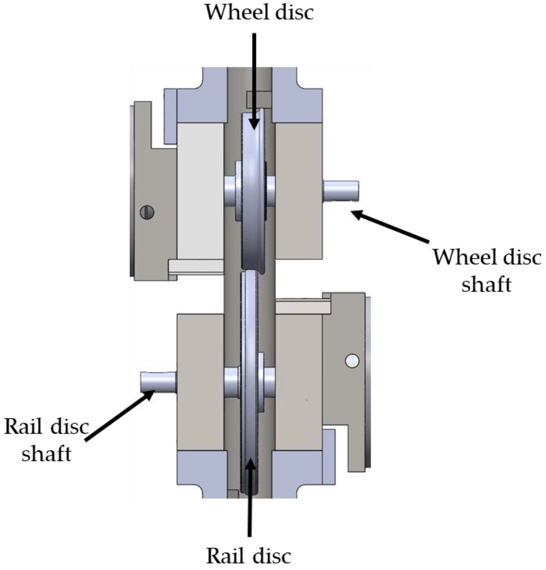
The core of the twin-disc tribometer is represented by the disc specimens (5) and (6). Each disc is mechanically connected to a motor assembly comprising a brushless motor (7), a shaft (8), an encoder, joints, and supports. The wheel and rail rollers both include a hub (9), connected to the corresponding shaft, and an outer rim machined to the desired scaled wheel/rail profile. This strategy allows us to only replace the rim after severe wear and to test different combinations of wheel and rail materials/profiles, thus allowing us to reduce the setup costs. A detailed view of the contact between the wheel and rail discs is shown in
Figure 2. The supports of both motors are connected to the two plates (3) and (4), on which specifically designed slotted holes are machined in order to adjust the relative position between the contacting discs. As shown in
Figure 1c, the upper plate (3) is guided in the vertical direction by linear bearings (10), and slides on the vertical traction rods (2) connecting the two plates. The linear bearings are fundamental to avoid a loss of vertical load due to friction forces since the applied load must act entirely on the contact patch.
To simulate different axle load values, the bench includes a system for the application and adjustment of the normal load at the contact interface between the rollers. After exploring different solutions, the choice is a system based on helical springs (11), which act between the loading beam (12) and the upper plate (3). Compared to rigid loading systems, where the profiles are pressed without elastic elements, the selected solution ensures a limited loss of the contact load when the profiles are worn out. A linear potentiometer (PZ34 series) (13), mounted between the upper plate and the loading beam, allows us to accurately measure the load applied by the loading system. The upper (3) and lower (4) plates, loading beam (12), and traction rods (2) are designed with well-known structural mechanics formulas to ensure a desired large stiffness value to limit elastic displacements, so they are largely over-sized and can operate safely against mechanical failure. The helical springs are instead selected from commercial catalogues to guarantee a target stiffness value, and their static and fatigue verification is carried out with standard machine design formulas.
The creepage between the two discs, subjected to an adjustable normal load, is achieved through a pair of independently controlled motors. More in detail, the angular speed of each disc is controlled by a synchronous permanent magnet (brushless) motor ACM BRL 220, manufactured by ACM Engineering S.r.l, located in Bardello, Varese, Italy, providing a maximum torque of 650 Nm and a nominal torque of 150 Nm@2000 rpm. Motors include high-resolution digital encoders that are used to measure the rotational speed of each roller. The motors and axle boxes are refurbished from test benches developed in past activities featuring working conditions that match the ones of the new twin-disc rig, thus ensuring the safe operation of the main components of the motor and axle box units.
2.1. Scaling Strategy
As stated before, it is necessary to adopt an optimal scaling strategy when designing a scaled test rig, depending on the quantities of interest. The similitude model by Pascal is selected for the newly designed twin-disc, as this model ensures the same contact pressure for the full-scale and scaled system.
The most appropriate size scaling factor for the discs is selected considering several critical constraints, mainly the torque and rotational speed limitations of the readily available motors as well as the need for a compact size of the test rig. In fact, although Pascal’s scaling strategy is the most used when investigating the wheel–rail contact tribology, it still features some drawbacks. Precisely, Pascal’s strategy leads to a unitary scaling factor for peripheral speeds, thus requiring high values of the total power supplied to the discs. Small radii of the rollers would bring huge angular speeds, while large radii would require the motors to provide big torques. These limitations could be partially overcome with the installation of gearboxes, which, however, would increase the complexity of the bench layout and the overall costs of the test rig. Eventually, the size scaling factor is chosen equal to ψ = 5, since this value allows for adopting the motors and some of the components realised by the research group for test benches developed in past activities [
41,
42].
Table 1 shows the most critical operating conditions that can be reproduced on the newly designed bench considering a nominal friction coefficient of 0.4. The table also provides the values of the main quantities that need to be adjusted on the bench during the test. The values of torque correspond to continuous operations of the two motors, but larger values, corresponding to a higher friction coefficient, can be provided in case of short-term overloading conditions.
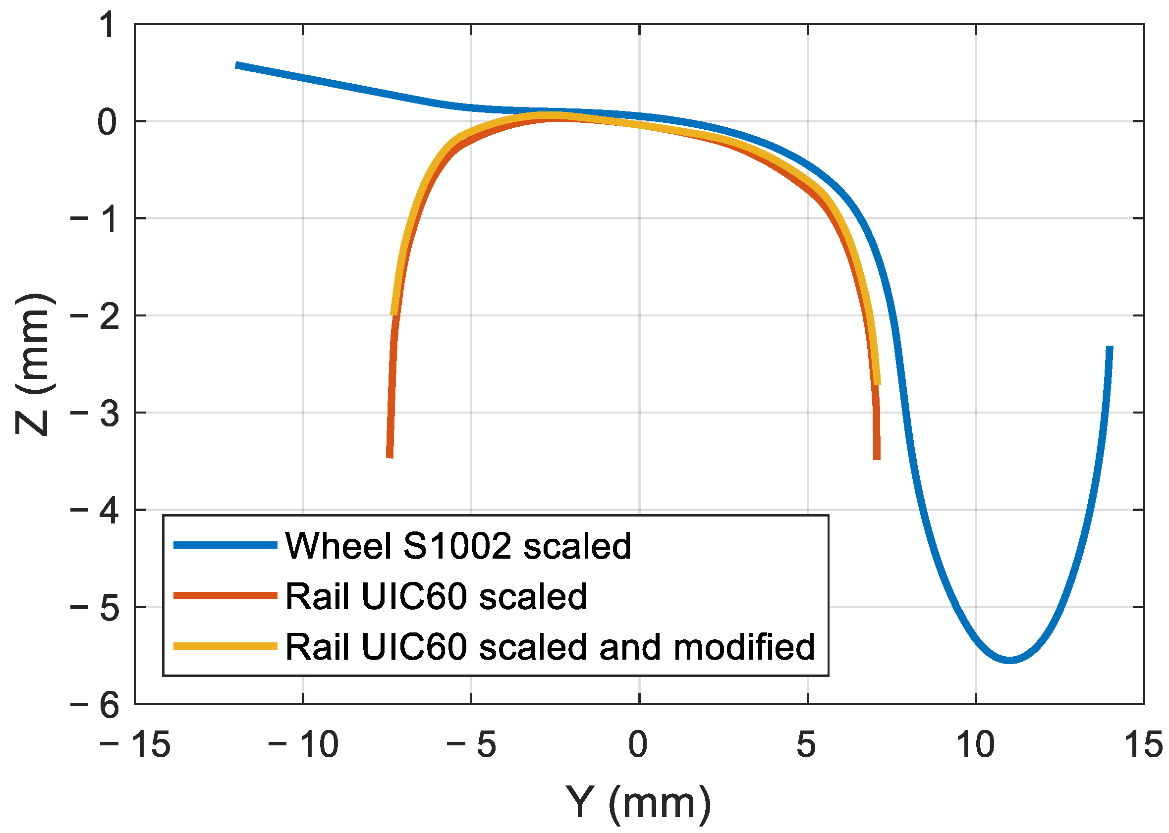
As stated above, Pascal’s similitude model theoretically allows the maintenance of a constant normal contact pressure in the full-scale and scaled systems. Nonetheless, when simulating the wheel–rail contact on a twin-disc, the rail roller features a longitudinal curvature, while the real rail has an infinite curve radius in the longitudinal direction. Therefore, to maintain the same contact pressure, without altering the scaling factor for the normal load, the transversal curvatures of the bodies should be corrected. A major novelty of the new test bench indeed involves a change in the lateral curvature of the rail roller profile to ensure that when simulating a desired normal load, the contact pressure obtained on the bench is the same pressure produced on the full-scale wheel–rail contact. Obviously, this is a compromise solution, which ensures a proper scaling of the contact patch area but modifies the aspect ratio of the contact ellipse.
Currently, the profile of the wheel disc is machined to the S1002 profile with a scaling factor of 5 (see
Figure 3). Nonetheless, as the wheel discs are made of a machined rim mounted on a hub, the bench can be adapted to test different types of profiles by simply changing the outer rim. On the other hand, the disc representing the rail is machined starting from the standard rail profile of the UIC60 rail canted 1:20, with a slight change in the lateral curvature for the above-mentioned reasons (see again
Figure 3).
The required value of the lateral curvature of the rail disc can be calculated iteratively with the application of Hertz’s theory of contact, changing the value of the curvature until the desired value of contact area (and hence pressure) is achieved. According to Hertz’s theory, the contact area between two bodies is an ellipse with semi-axis a and b, which can be calculated as follows:
where
F is the normal load;
E and
ν are Young’s and Poisson’s moduli, respectively; and the subscripts
w and
r denote the wheel and rail discs, respectively.
The coefficients
α and
β are a non-linear function of the equivalent curve radius
Req, as stated in the expressions below:
where
Rwx,
Rwy,
Rrx, and
Rry are the longitudinal (subscript x) and lateral (subscript y) curve radii of the wheel (subscript w) and rail (subscript r) discs.
The maximum contact pressure can be then calculated as follows:
Starting from the knowledge of the longitudinal curve radius of the wheel
Rwx = 92 mm, longitudinal curve radius of the rail
Rrx = 132 mm, and lateral curve radius of the scaled S1002 wheel profile at the nominal contact point
Rwy = 64 mm (see the reference system in
Figure 4), an iterative calculation is performed to determine the required lateral curvature of the rail profile at the contact point to obtain a unitary scaling factor for the contact pressure. It is found that the lateral rail curve radius on the scaled bench should be set equal to
Rry = 184 mm.
2.2. Design
Steels suitable to realise wheels and rails are commonly listed in international standards. Typically, wheels are realised in R7 steel, while rails are realized in R260 steel. Obtaining the raw material for these types of steels with a shape suitable to realise the rollers is quite challenging, e.g., the rail roller should be realised starting from a real rail, requiring a very complex design and very high costs. For this reason, the first set of rollers is realised with steels that have chemical properties similar to the ones listed in the EN standards. Since hardness is the main mechanical property that affects the wear behaviour, thermal treatments are used to obtain rollers that have hardness values close to those of real wheels and rails.
During the experimental tests, the rollers are subjected to wear, leading to a modification of the original profile and affecting the contact area and pressure. To reuse the same pair of rollers for several wear tests, they were designed to be machined several times to restore the required profiles, reducing the costs of the test bench setup.
Because of the wear of the profiles during tests, it is necessary to design a loading system able to maintain a constant contact load also when the roller radii change due to material removal. To achieve this requirement, the contact load is applied to the wheel roller (the upper disc) by means of a couple of helical springs, which are preloaded by means of a screw system. The selection of the appropriate springs to simulate the required axle load and the maximum load reduction due to wear is a crucial aspect of the test rig design. The adopted spring must guarantee the application of the maximum design contact load without reaching its limit deflection. Furthermore, the spring stiffness should be designed in order to reduce the load loss caused by the wear of the contacting discs as much as possible. In fact, when the profiles are worn out, the upper plate approaches the lower plate, thus increasing the spring length and consequently reducing the applied force. This phenomenon could be completely avoided with the adoption of a hydraulic cylinder to generate the vertical load, but this solution would entail increased costs and a more complex mechanical arrangement. Therefore, as a proper value of the spring stiffness can still partially mitigate this issue, the spring loading system is selected to be installed on the bench. The selected stiffness of the helical springs (k = 29.87 N/mm) assures a load decrease equal to 2.4% of the maximum contact load (corresponding to axle load of 22.5 tons), when the radius of each disc is reduced by 1 mm.
To verify the actual normal load acting between the rollers and to calibrate the position transducer (element (13) in
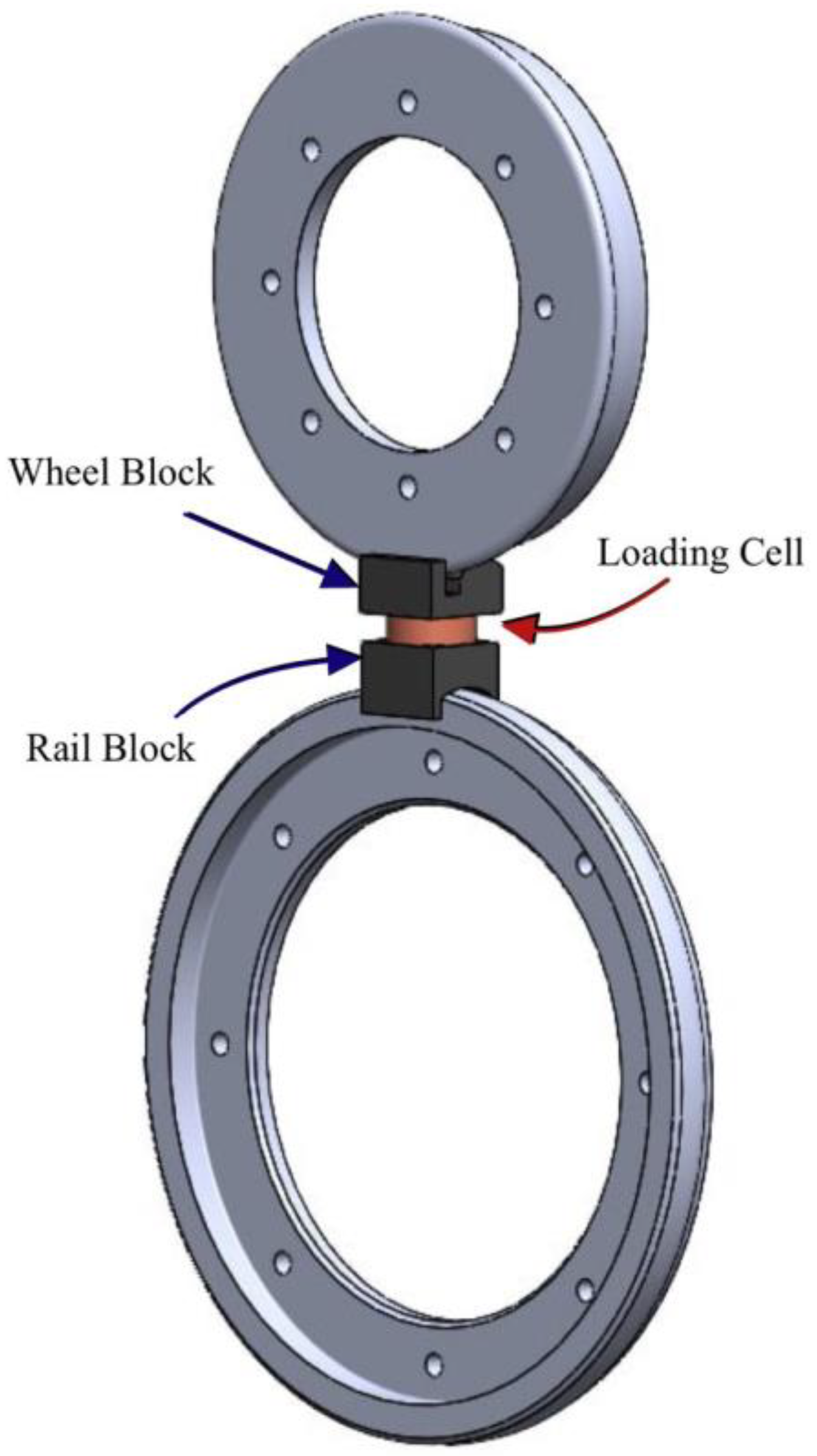
Figure 1a), a setup process is defined. Before running the wear tests, two special elements, which fit the profiles of the discs, are positioned between them, as shown in
Figure 5. These elements allow the installation of a button load cell between the rollers, thus verifying, from the spring compression, if the applied load corresponds to the desired one, hence estimating possible load loss due to friction. This initial calibration ensures that the desired load can be accurately applied between the discs. It is expected that load loss due to friction is very low since the vertical sliding of the upper plate is guaranteed by a couple of linear bearings, as shown in
Figure 1c.
2.3. Testing Procedure
The configuration of the new twin-disc, based on two independently controlled brushless motors, allows for performing different types of tests. By controlling the angular speed of each motor, a constant creepage can be achieved at the contact interface. This kind of control can be adapted to carry out wear tests at different values of creepage, reference speed, and normal load, measuring the amount of worn material on the surfaces of the contacting bodies at discrete times with a laser system already available in the laboratories of the research group [
43,
44,
45]. The wear tests will be run to tune the wear coefficient for different operating conditions of real passenger and freight vehicles. More in detail, one of the most widely used approaches to estimate wear in the railway field is Archard’s wear law [
46], which calculates the amount of worn volume
Vremoved as follows:
where
N is the normal load,
ds is the sliding distance,
Hs is the Brinell hardness of the softer contacting material, and
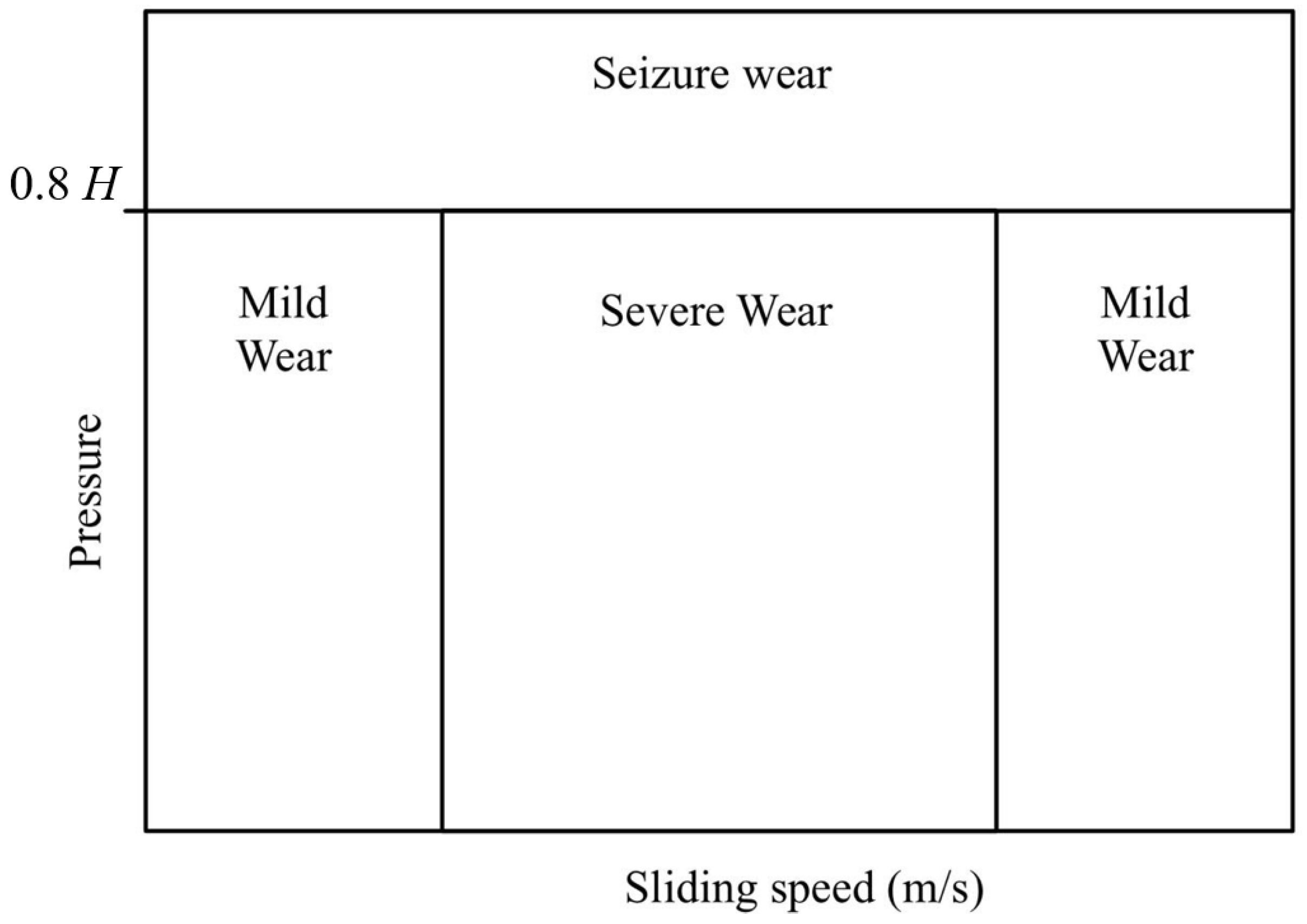
kArch is the wear coefficient. The latter is commonly evaluated as a function of contact pressure and sliding speed from experimental maps that usually feature four wear zones (see
Figure 6). One of the most widely used maps is the one obtained from work carried out at the Swedish Royal Institute of Technology (KTH) [
47]. Typically, constant coefficients are taken for each zone, and their values as well as the boundaries of each zone are obtained from literature data obtained in a range of different conditions. Therefore, it is believed that the major features of the newly designed bench, namely the use of scaled profiles and the correction of the lateral curvature of the rail disc profile compensating for the introduction of a longitudinal curve radius of the rail, will allow us to derive more refined maps from testing conditions that can be easily related to real operations of railway vehicles. The same strategy will be used to tune the wear coefficients for other wear laws that are commonly adopted in the literature, relating the amount of worn material to the energy/power dissipated at the contact patch, such as the laws proposed by Krause and Poll [
48], Zobory [
49], the British Rail Research (BRR) centre [
50], and Sheffield University (USFD) [
51].
The same control approach as for the wear tests can be also applied to derive experimental adhesion curves by recording the torque provided by each motor and the speed of both discs in steady-state conditions for different values of creepage and contamination at the contact patch.
On the other hand, a different kind of test can be performed by setting a constant speed for one disc while progressively increasing the resistant torque on the other roller, thus achieving an increasing creepage. This strategy enables the measurements of adhesion curves in dynamic conditions, whereby the creepage at the contact interface changes quickly until approaching full slip conditions.
3. Multibody Model
In addition to being used to experimentally determine Archard’s law coefficients, the twin-disc test rig will be used to validate wear algorithms implemented within commercial multibody codes [
52]. For this reason, during the design activity, a numerical model of the twin-disc test rig was realised in the Simpack environment. The model, shown in
Figure 7, includes the roller rail that is connected to the main bench frame by a rotational degree of freedom (DOF). The bench frame is composed of two bodies, i.e., the main frame and the upper frame. The former is modelled as a body with 0 DOFs, since it is rigidly connected to the inertial system, while the latter has 1 DOF in the vertical direction with respect to the main frame.
The last body in the model is the wheel roller, which is connected to the upper frame of the bench by means of the Simpack general rail–track joint. A constraint element, based on Lagrange multipliers, is used to only allow the rotational degree of freedom to the wheel roller. The use of a general rail–track joint is strictly necessary in order to define the contact pair element. The normal force is determined by the equivalent elastic method, while tangential forces are calculated using the FASTSIM algorithm, considering a friction coefficient of 0.4.
The vertical load is realised by means of two point-to-point force elements, acting between the upper frame and the main frame, that simulate the test bench loading system. The speed of the two rollers is controlled by means of Simpack PID control elements, implementing the behaviour of the motor drives used to actuate the rollers. Wheel roller wear is calculated using the Simpack Wheel Profile Wear module, implementing Archard’s wear law. The update of the wheel profile after a predetermined travelled distance is realised by an in-house QtScript routine [
53]. The discrete updating and post-processing of the worn profiles are indeed key in improving the numerical stability of the method [
54].
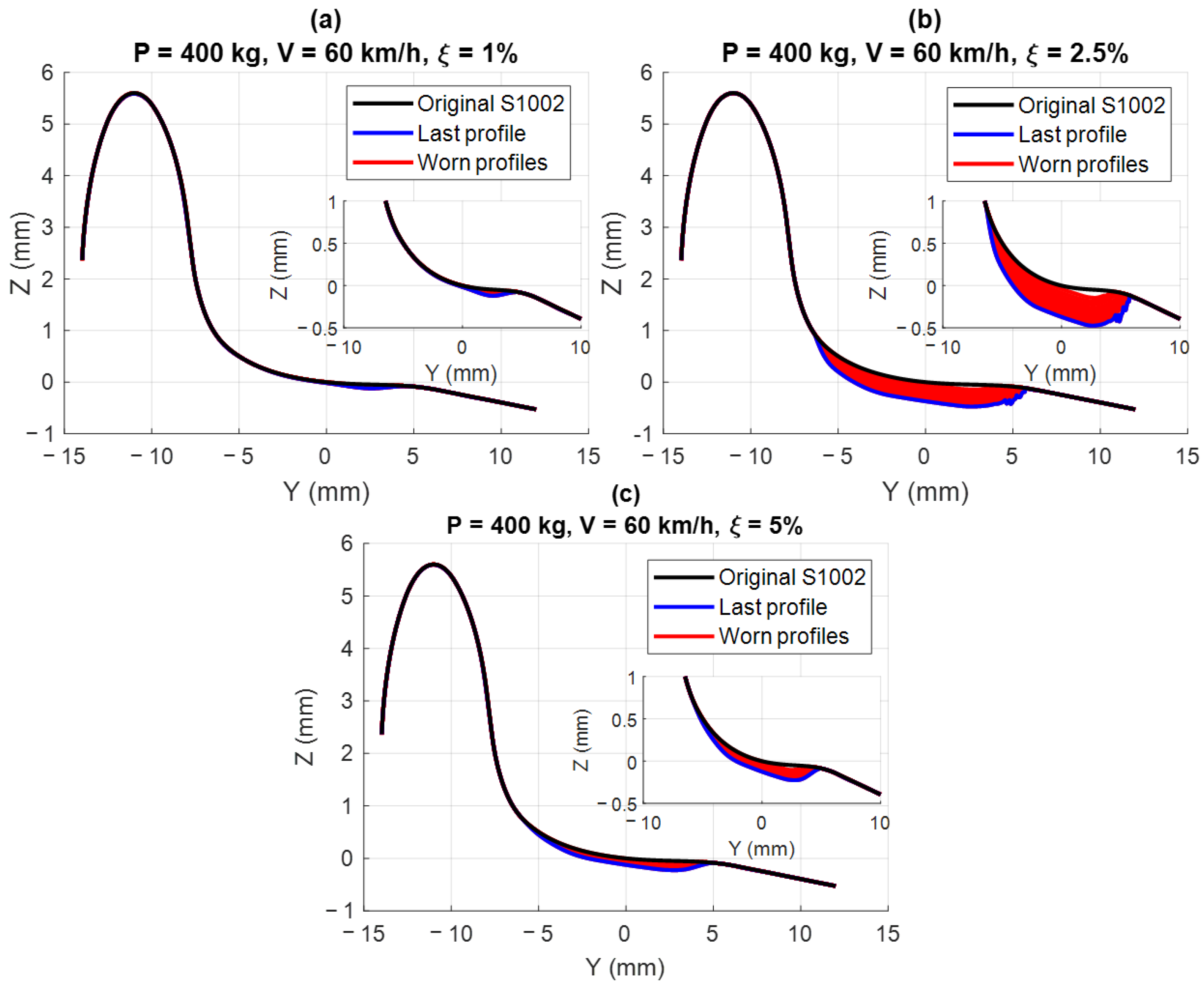
Preliminary simulations are performed for a typical operating condition of a European freight wagon running at 60 km/h with an axle load of 20 tons (400 kg on the test bench), considering different creep levels (ξ = 1%, 2.5%, and 5%). The adopted creep levels correspond to the mild 1, severe, and mild 2 regions of Archard’s wear map, respectively (see
Figure 6). This preliminary set of simulations is needed to obtain an approximated estimate of the expected wear prior to the bench installation. This allows us to quantify the time interval between successive replacements of the wheel and rail disc rims. At this stage of the activity, simulation results are obtained considering literature data for the wear coefficients and Archard wear map, but they are useful to understand the expected wear rate and the evolution of the shape of the wheel profile. In future activities, the wear map used in the simulations will be tuned against experimental data collected from the bench.
For each creepage level, the evolution of the wheel profile is evaluated for a total rolling distance of 80 km (corresponding to 400 km on the full-scale system), with profile replacement every 200 m (1 km on the full-scale system), thus performing 400 iterations. Please consider that this simulation distance corresponds to a large amount of distance travelled by a real vehicle, as creepage at the wheel–rail contact is always well below 1%. The results of the simulations are shown in
Figure 8, which displays the original, final, and intermediate worn profiles during the simulation for the three tested creepage levels, with zoom on the worn region. For all cases, wear occurs on the tread, where the nominal contact point is located. As expected, the largest amount of wear is obtained for the creepage value of 2.5% (
Figure 8c), which corresponds to the severe region of the wear map, featuring a larger wear coefficient. The final profile for this value of creepage looks harsh, and this means that the large amount of wear is leading to numerical instabilities that may be caused by incorrect values of the wear coefficient. Therefore, the results of the numerical simulation confirm that further investigation is needed to obtain proper wear coefficients for the simulated conditions.
4. Conclusions and Future Developments
After reviewing various tribometers from the literature and highlighting their key characteristics, this paper presents an innovative design for a twin-disc test rig for railway applications. A common limitation observed among these test rigs is the use of disc specimens that fail to accurately replicate the profiles of real wheels and rails. The proposed twin-disc tribometer addresses this limitation by using discs with lateral profiles closely resembling those used in real applications, considering the standards ORE S1002 for the wheel and UIC 60 for the rail. Furthermore, the lateral curvature of the rail disc is slightly adjusted so as to replicate the same contact pressure for a set axle load, using Pascal’s similitude model.
The main characteristics of a twin-disc tribometer are the normal force and the slippage between the discs. The first one is achieved via compression springs, a cost-effective solution that allows maintaining constant contact pressure. Creep between the discs can be easily obtained by powering each shaft with an independent AC motor.
The rig is designed to simulate the conditions of heavily loaded European freight wagons, withstanding an axle load of 22.5 t and a speed of 60 km/h, but it can also replicate the operating conditions of passenger vehicles. Therefore, the rig is able to simulate a vast array of real contact conditions.
The design concept shown in the paper as well as the results of the preliminary MB simulations prove that the newly designed test rig can be effectively and reliably adopted to gain a further understanding of wear in a controlled laboratory environment. Therefore, the newly designed bench components are currently being manufactured and the twin-disc rig will be installed in the laboratories at Politecnico di Torino. The bench will be used to perform wear test campaigns by independently controlling the speed of both shafts to achieve desired creepage values. The experimental results will drive the definition of more refined wear maps, based on the measurements performed on the bench, that include the measurement of the worn profiles through a laser scanner system already available in the lab.
The twin-disc bench will be used to validate wear algorithms currently adopted in commercial multibody codes. For this reason, a detailed multibody model of the test bench is realised in the Simpack environment. The model is used to obtain preliminary worn profiles of the wheel roller.
Future work regarding the test rig includes designing and adding a tread braking system with scaled shoes to the tribometer. These will be used to brake the wheel disc so that the bench will enable the execution of tests to investigate the wear and thermal behaviour caused by tread braking operations as well.

