Article

Optimising Lead–Air Battery Performance through Innovative Open-Cell Foam Anodes

1
Laboratory of Biomaterials and Transport Phenomena (LBMTP), University Yahia Fares, Medea 26000, Algeria
2
Faculty of Sciences, University of Medea, Nouveau Pôle Urbain, Medea 26000, Algeria
3
Laboratoire de Génie des Procédés Chimiques, Department of Process Engineering, University of Ferhat Abbas, Setif 19000, Algeria
4
École Nationale Supérieure de Chimie de Rennes, CNRS, ISCR (Institut des Sciences Chimiques de Rennes)–UMR 6226, Université Rennes, F-35000 Rennes, France
5
Research Unit on Analysis and Technological Development in Environment (URADTE-CRAPC), Tipaza BP 384, Algeria
6
Laboratoire de Recherche sur le Médicament et le Développement Durable (ReMeDD), Department of Environmental Engineering, University of Salah Boubnider Constantine 3, El Khroub 25012, Algeria
7
School of Engineering, Merz Court, Newcastle University, Newcastle upon Tyne NE1 7RU, UK
*
Author to whom correspondence should be addressed.
Designs 2024, 8(4), 61; https://doi.org/10.3390/designs8040061
Submission received: 26 March 2024 / Revised: 20 May 2024 / Accepted: 13 June 2024 / Published: 21 June 2024
(This article belongs to the Special Issue Design and Manufacture of Electric Vehicles)

Abstract

:
In the dynamic realm of sustainable energy storage technologies, the global research landscape presents myriad scientific and economic challenges. The erratic growth of renewable energies alongside the phasing out of conventional power plants poses a significant hurdle in maintaining a stable balance between energy supply and demand. Consequently, energy storage solutions play a pivotal role in mitigating substantial fluctuations in demand. Metal–air batteries, distinguished by their superior energy density and enhanced safety profile compared to other storage devices, emerge as promising solutions. Leveraging the well-established lead–acid battery technology, this study introduces a novel approach utilising open-cell foam manufactured through the Excess Salt Replication process as an anode for lead–air battery cells. This innovation not only conserves lead but also reduces battery weight. By employing a 25% antimonial lead alloy, open-cell foams with diameters ranging from 2 mm to 5 mm were fabricated for the antimonial lead–air battery. Preliminary findings suggest that the effective electrical conductivity of primary battery cells, measured experimentally, surpasses that of cells composed of the same dense, non-porous antimonial lead alloy. This improvement is primarily attributed to their extensive specific surface area, facilitating oxidation–reduction reactions. A correlation between effective electrical conductivity and cell diameter is established, indicating optimal conductivity achieved with a 5 mm cell diameter. These results underscore the feasibility of implementing such an electrical system.

1. Introduction

Nowadays, all studies in the field of energy storage are trying to improve the electrical performance of batteries while making them lighter [1,2,3,4,5,6,7]. Despite this, lead–acid batteries are still the most widely used; for example, in the automotive industry, as of 2010 they accounted for 99% by weight of batteries used in this field. The main advantages of this technology are its low cost at around 150 €/kWh [8] and its good efficiency of 75% to 80% [9]. Its simplicity and strength have made it the leader in the field of energy storage for more than one and half centuries. Many researchers are trying to overcome the drawbacks of these batteries, either by improving the electrolyte or by working on the electrode alloys [10,11,12,13,14,15], or even by the development of lightweight lead–acid battery grids [16,17,18,19,20,21,22,23] which may reduce cost, effort, and materials. Lach et al. [24] confirmed that the replacement of a standard grid in a lead–acid battery with a reticulated vitreous carbon (RVC) or conductive porous carbon (CPC) leads to a reduction in battery weight and lead consumption of about 20%.
Recently, metal–air batteries (MABs) have emerged and been intensively studied as promising and efficient batteries for different applications [25,26,27,28,29]. They are compact and lightweight energy sources with a high energy density [28,30]. In such electrochemical systems, oxygen from the air is used as a cathode along with a liquid electrolyte. This contributes to lowering the cost and weight of the MABs. Metal electrodes can be zinc, lithium, magnesium, aluminium, and other metals. The fundamental working concept of this device is to electrochemically reduce O2 from the air and oxidise the metal electrode, resulting in the formation of solid metal oxides that may be recycled [26].
Different metals have been used as electrodes for MAB. Zinc–air batteries (ZABs) are the only fully developed metal–air systems currently available, and they have been successfully marketed as non-rechargeable cells for several decades. Nevertheless, Pei et al. [31] stated that the lifespan and electrical rechargeability of ZABs are both limited. Even the Li–air battery is considered the most promising among the other MABs, but it cannot be industrialised currently. Akhtar et al. [32] concluded that the low discharge rate, lower number of cycles, oxidation of the lithium anode, discharge products at the cathode, and side reactions inside the battery were the key limiting factors in the slow progress of Li–air batteries on an industrial scale. Rechargeable Na–air batteries are the subject of great interest nowadays because of their high theoretical specific energy density, lower cost, and lower charge potential compared with Li–air batteries. However, high-purity O2 used as a working environment is required to achieve high performance, which obstructs their application as a high-energy-density battery [33]. Aluminium–air batteries using alkaline electrolyte have good battery performance, especially under a high discharge current. However, alkaline electrolytes and aluminium electrodes tend to be highly corrosive, and the main problem restricting the feasible usage of Al–air batteries is the low coulomb efficiency resulting from the self-corrosion of the electrode. To overcome this problem, aluminium alloys were chosen as the electrode material [34]. Zhao et al. [35] reported that adding vanadate or phosphate as a corrosion inhibitor to the NaCl electrolyte significantly improved the performance of Mg–air batteries, and phosphate showed a stronger inhibiting effect than vanadate. Sn–air batteries are another type of MAB which operate at room temperature with an electrolyte of methane sulfonic acid and polyacrylamide gel [36].
Most recently, Milusheva et al. [30] showed the possibility of the utilisation of the lead–air electrochemical system as a power source. This system consisted of a standard lead electrode and H2SO4 electrolyte used in the lead–acid battery and a gas diffusion electrode which was sufficiently stable in the sulphuric acid electrolyte. They concluded that the energy values obtained at laboratory conditions provided a good perspective for a practical application of the lead–air system for energy storage and in the automobile industry.
The most common customer complaints about power supply systems have always revolved around two factors: battery life and weight, especially for vehicles. Because it takes less energy to accelerate a lighter object than a heavier one, lightweight batteries offer great potential for increasing vehicle efficiency.
It is believed that the porosity of foams can provide high specific surface area where redox reactions take place and improve electrical conductivity [37] for more lightweight batteries in the future. The objective of this experimental work is mainly the study of the usage and electrical performance of cellular materials like open-cell metal foams as direct active electrodes in these kinds of batteries since only a few works exist on these batteries [28,38,39,40]. These foams were made available through a new variant of the space holder replication technique developed using salt (NaCl) as a removable preform. This variant was named the Excess Salt Replication process (ESR process) [41]. In order to obtain samples of good quality, metals and alloys of good castability are highly recommended, like the 25% antimonial lead alloy (25% Sb-Pb), among others, which can give samples of porosity between 46% and 66%. These open-cell foams were made from grains of salt with diameters ranging from 2 mm to 5 mm. So, the choice of the 25% antimonial lead alloy concentration is based on technical reasons related to the ESR process, because it is well known that at concentrations above 4% of antimony (Sb), it tends to be released from the grid into the electrolyte during operation and charging in lead–acid batteries. The released antimony is deposited on the lead foam of the negative plate [42]. This results in a reduction in hydrogen overvoltage, and the local lead and antimony cells on the negative plate also cause an open-circuit loss of charge. So, it is desirable to reduce the antimony content as much as possible in order to reduce open-circuit losses and to make the battery cell resistant to the adverse effects of overcharging, which tends to occur with automotive batteries charged from AC sources, e.g., alternators. Nevertheless, antimony is generally added to improve the strength and castability of the alloy and for its high corrosion resistance [43]. The effect of Sb concentration in the antimonial lead alloy designed for the electrode of these metal foam–air battery cells (MFABs) will be discussed in further research.
Scientific work on the electrochemistry of cellular materials is very scarce and only a few data on the electrical conductivity of cellular metals have been reported so far [44,45]. On the other hand, when analysing these relative electrical conductivity values from different authors, it is found that they are very different, mainly for foams produced by space holder or replication methods. Each foam has a different structure of its own since their manufacturing processes are different [46], and therefore individual foams need to be characterised experimentally. No one, to our knowledge, has yet studied or proposed the use of this type of cellular material obtained with the salt replication process in MABs.
This study attempts to consolidate the electrochemical data on the performance of cellular materials in the field of energy storage, and especially in MABs, in order to make them lighter. Batteries are known as either primary, i.e., not rechargeable, or secondary, meaning that they can be recharged. In this study, primary in-laboratory reconstructed battery cells are considered.
Firstly, the effective electrical conductivity (EEC) of MFAB cells using ESR foams as electrodes is measured.
Secondly, the advantages of these MFAB cells are revealed through the comparison of their EEC with that of the MAB cell with non-porous electrodes made from the same dense alloy (25% Sb-Pb). These EECs are regarded as the measurement of apparent electrolyte–foam interaction conductivity.
Then, the identification of the electrochemical reactivity of the electrodes is necessary for confirming that they are indeed MFAB cells where the electrochemical reactivity of the ESR foam electrode is the origin of the MFAB cell electrical current.
Fourier-transform infrared spectroscopy analysis of the external surface of the ESR dense electrode is performed before and after cell tests. The effect of the cell diameter of ESR foam electrodes on the measured EEC is finally analysed.
The novelty of this work lies in introducing an innovative approach to enhance the performance of lead–air batteries. This approach involves the use of open-cell foam anodes manufactured through the Excess Salt Replication process. Utilising this method enables the conservation of lead while reducing the battery’s weight. Furthermore, this approach has improved the effective electrical conductivity of the cells and promoted oxidation–reduction reactions through an extended specific surface area.

2. Materials and Methods

It is appropriate to reconstruct metal foam–air battery cells using different ESR foams obtained for salt grains, diameters between 2 mm and 5 mm, and then to measure their cells’ effective electrical conductivities (EECs), Km (µS/cm).
Because the direct measurement of the electrical conductivity of a cellular material is very hard, it is assumed that the delivered electrical current from the interaction between these electrodes and the H2SO4 electrolyte, in the presence of O2 from the air (as cathode), is representative of the electrical conductivity, which is named in this case the “effective electrical conductivity”, and it could be used to compare the electrical performance of cellular ESR electrodes and that made from the dense alloy of the same composition, 25% Sb-Pb.
The ESR process is a simple and inexpensive technique based on the space holder replication method for the elaboration of cellular materials. It consists of four steps, which are fused metal infiltration of the salt preform, excess salt compaction, sample cooling, and salt leaching [41]. Good open-cell foams with two different alloys were made with this process, namely, 25% antimonial lead alloy, which has a porosity ranging from 46% to 66%, and zamak 5, which has a porosity ranging from 58% to 65%. These two alloys have good castability, good fluidity, and low melting temperature below that of the salt (Tm salt = 801°). In this work, only 25% antimonial lead alloy was investigated.
A series of electrochemical tests were carried out on reconstructed MFAB cells in the laboratory. Electrodes manufactured by the ESR process were used as anodes, and the available oxygen O2 in the air was the cathode. So, the 25% SbPb–air cell was the MFAB designed with the equipment shown in Figure 1. This experimental stand comprising these cells was carefully designed to explore the necessary conditions and the results of these tests:
  • The ESR foam electrodes were carefully cut into regular stick shapes before the salt removal (Figure 1).
  • The density of the dried foams was measured by Archimedes’s principle and then the porosity P was calculated [41]
  • Before and after each test, the ESR foam anode and the dense Pb were weighed.
  • Stirring was carried out by the laboratory stirrer (Figure 1) for achieving good distribution of the existing species during the chemical reactions and for better dissolution of oxygen from the air in the electrolyte.
  • The last test used the same 25% Sb-Pb-dense alloy (non-porous material) as the anode for comparison.
  • A SELECTA CD-2005 Conductivity Meter (Figure 1) for electrolyte conductivity measurement and SELECTA pH-2005 pH Meter (Figure 1) electrochemical experimental apparatus were used simultaneously to measure the electrolyte’s electrical conductivity Km and pH every 1 min for 30 min, timed by a Diamond digital stopwatch (Figure 1).
  • The electrical current was measured once the electrodes were immersed in an agitated sulphuric acid H2SO4, with an average pH between 1.11 and 1.28 (Figure 1).
  • The entire sample had to be immersed in the sulphuric acid electrolyte to ensure that the properties studied were representative of the totality of the sample’s interactions with the electrolyte.
  • The temperature of the 100 mL of sulphuric acid was also measured with a digital thermometer (Figure 1) during every manipulation (T0 before the test and Tf at the end of the test) to explore the thermal stability of the cell.
  • Note that the battery cells were named “SbSPb X”, where SbS stands for the anode foams obtained from the ESR process (see [41]); Pb was the non-porous dense lead electrode used for electrical circuit closure. A multimeter was used to check electrical current flow, too, and it will be shown later that this electrode did not contribute to the electrochemical reactions of the cell. X represents the value of the salt grain diameter. Table 1 regroups the measured and calculated parameters of all tested samples.
The operational method for each battery cell test is summarised as follows:
When the two weighed electrodes are fully immersed in an agitated sulphuric acid, the measurements of EEC, T, and pH are taken every 1 min for 30 min; then, the dried electrodes are weighed again after cell tests; and finally, the average EEC, Km (µS/cm), is calculated.

3. Results and Discussion

3.1. Interpretation of Measured Effective Electrical Conductivity Results

Commonly, MFABs are electrochemical systems which rely on metal oxidation and oxygen. Oxygen from the air is used as a cathode along with a liquid electrolyte (H2SO4), and the metal is the anode.
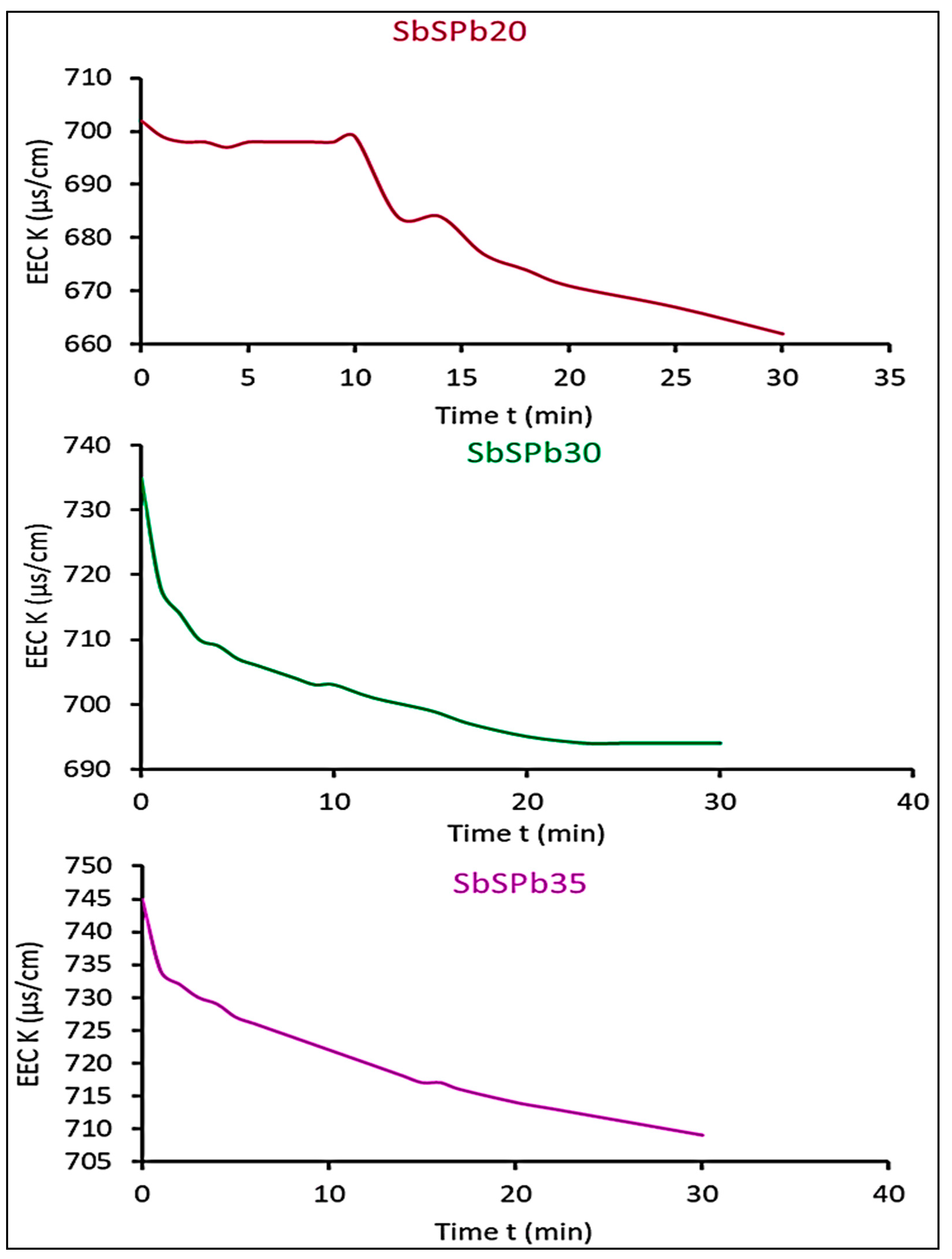
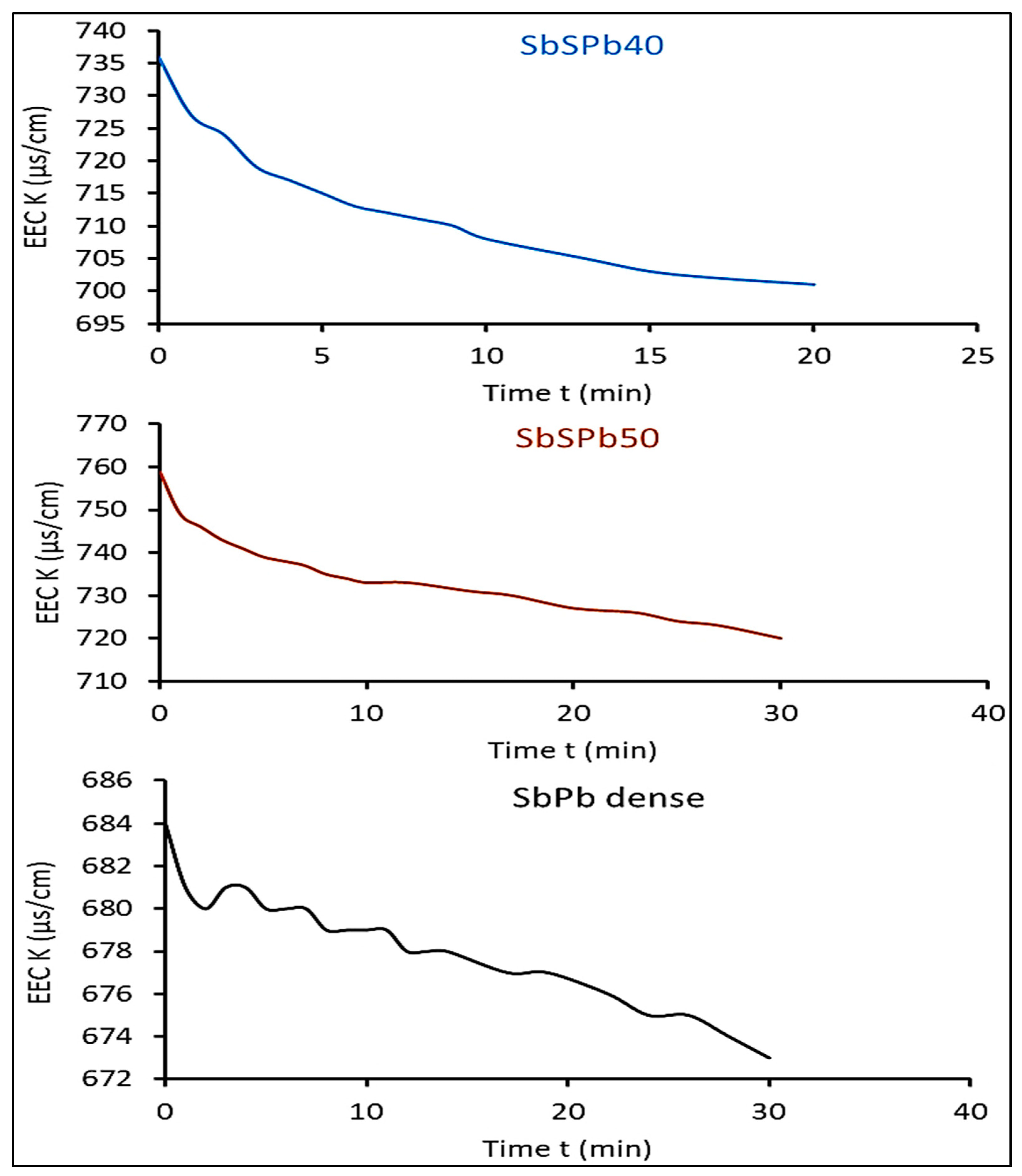
The curves in Figure 2 and Figure 3 show the individual electrochemical behaviour of each ESR foam.
The effective electrical conductivity (EEC) of all cells shows a decreasing trend with time.
The conductivity of an electrolyte depends on the amount of free water it contains [47,48], which explains the decrease in conductivity during all tests due to the spontaneous activity of water (consumption of H+ ions). Majima et al. [47], when studying the electrical conductivity of an acid sulphate solution, found that the addition of metal sulphates to an aqueous sulphuric acid solution causes a decrease in electrical conductivity, and this phenomenon is attributed to a decrease in the activity of water, which reflects a decrease in the amount of free water; and on the other hand, any increase in the concentration of H+ ions leads to an increase in electrical conductivity. As the cell discharges, hydrogen ions are removed so the concentration of hydrogen ions in the electrolyte decreases. The pH therefore increases like in lead–acid batteries [41].
Furthermore, there is a resemblance between the curve of SbSPb20 and that of dense SbPb which gives a gradual decrease; however, this is completely different from the others, which are rather soft, namely, SbSPb30, SbSPb35, SbSPb40, and SbSPb50.
Table 1 shows that there are no significant changes in temperature in general for all tested cells. This means that MFAB cells are thermally stable.

3.2. Advantages of ESR Foams and Electrodes’ Reactions

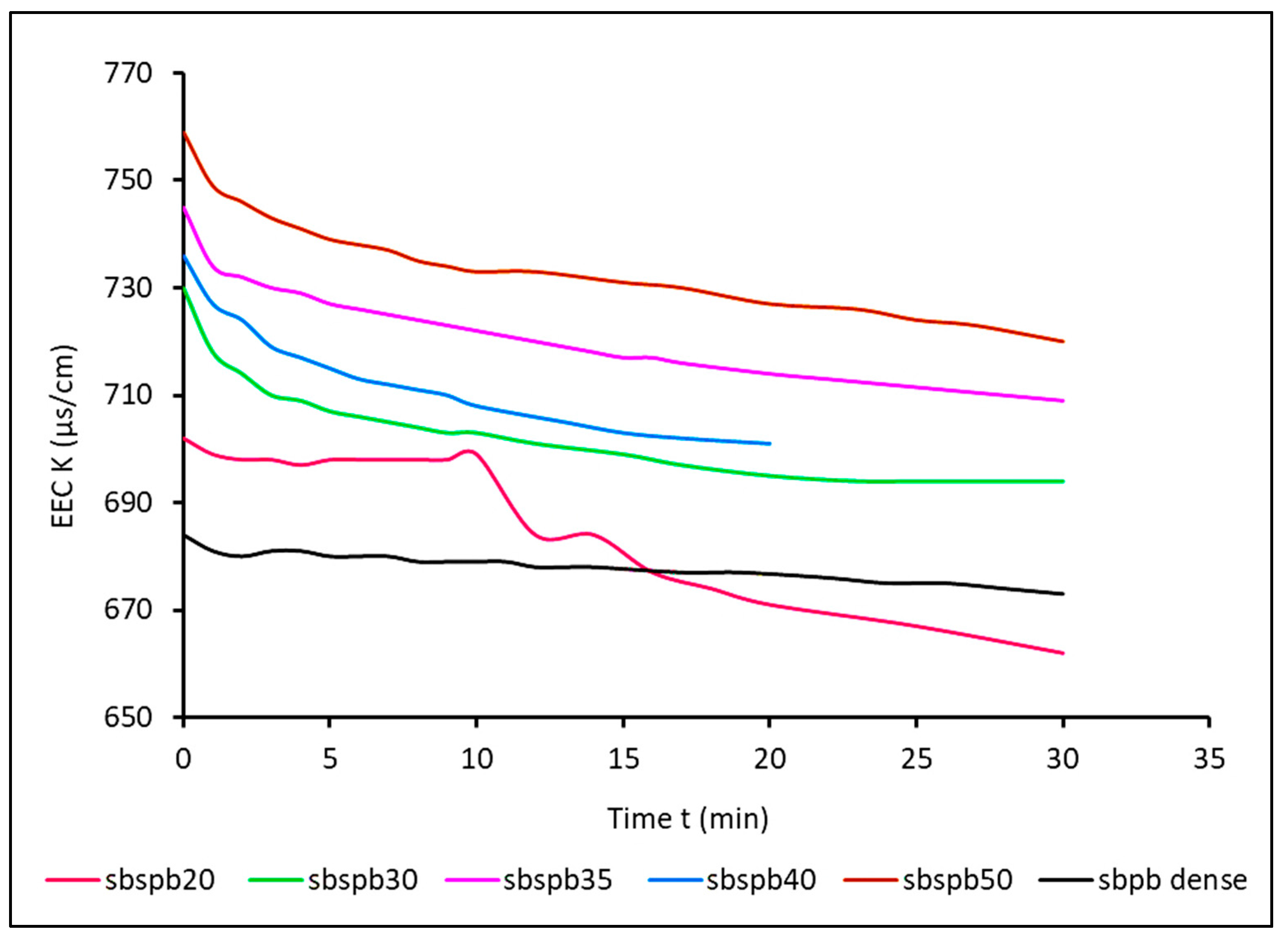
In order to compare the performance of MFAB cells to that of the non-porous dense alloy, all curves are regrouped in one graph shown in Figure 4. It is shown that the electrical conductivity values Km of sulphuric acid (considered the measure of the apparent conductivity of the interaction between the electrolyte and the foam) of all the MFAB cells are above that of the non-porous dense material.
From Figure 4, the curve of the Sb-Pb-dense cell is between 670 and 690 µs/cm, and all the curves of ESR foams cells are between 705 and 760 µs/cm. This clearly shows the superior electrochemical performance of all the foams compared to the use of the dense alloy (non-porous) of the same composition as the matrix of foam electrodes, regardless of their porosity or cell diameter. This is due to the remarkable specific active surface area of these foam anodes [49], which means in other words that when the anode is cellular, its interactions with the electrolyte are important because of the large surface where redox reactions occur, leading to an improved EEC.
When the electrode was immersed in the electrolyte (the beginning of the curves in Figure 4), spontaneous and automatic discharge without charge/discharge of the cells began, and then it continued slowly, until the equilibrium of the electron flowing in the circuit was reached. This means that the electrical conductivity reached the lower limit or a final threshold. There is a clear demarcation in the representative curve of SbSPb20 due to an aberrant measurement of this value.
Milusheva stated that the concentration of the acid electrolyte in a Pb–air cell varies with the state of charge in a similar way to a conventional lead–acid battery [30] according to this scheme of reactions:
Reaction at cathode:
O 2 + 2 H 2 S O 4 + 4 e 2 H 2 O + 2 S O 4 2
Reaction at anode:
P b + 2 S O 4 2 2 P b S O 4 + 4 e
The overall reaction:
O 2 + P b + 2 H 2 S O 4 P b S O 4 + 2 H 2 O
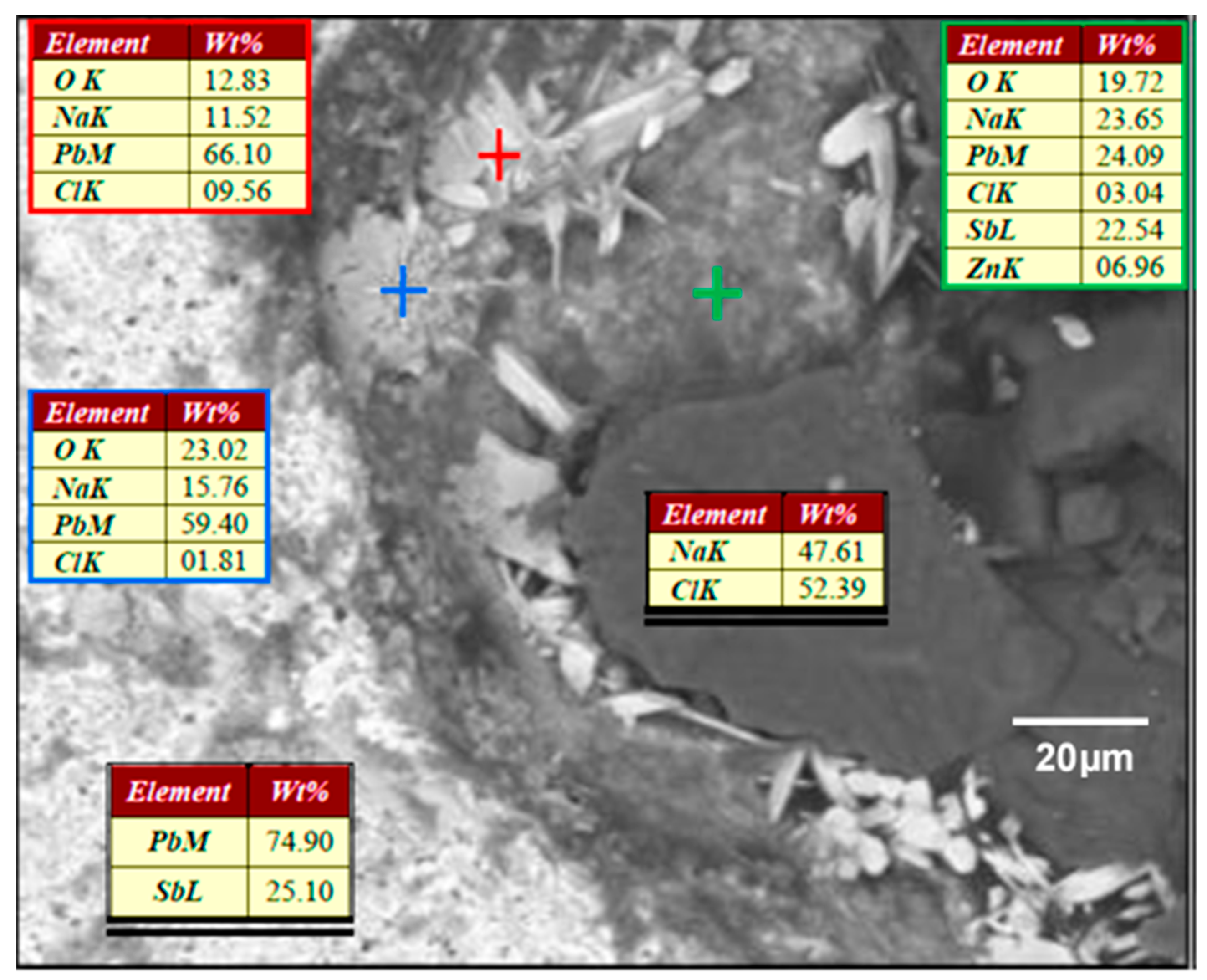
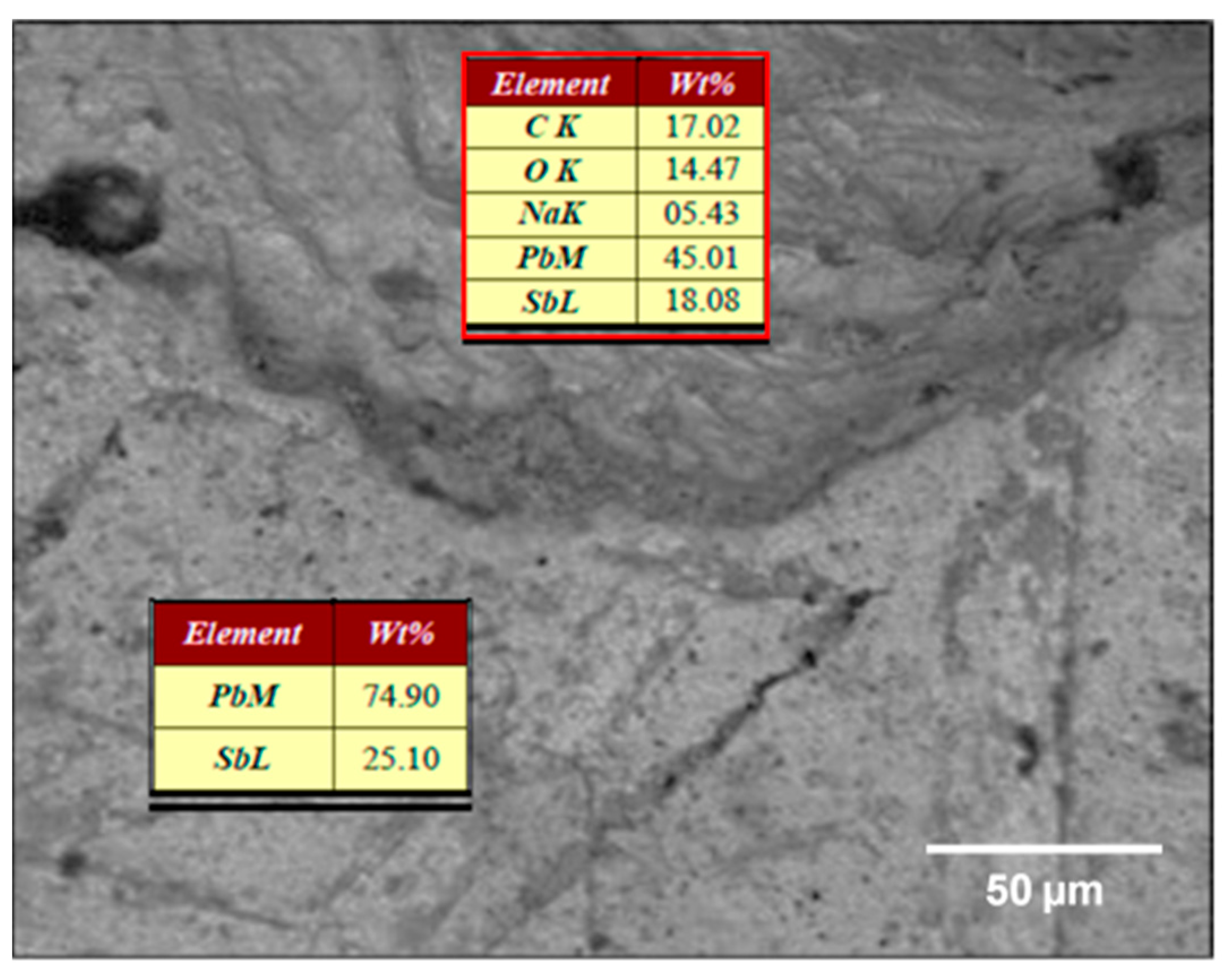
Hassein-Bey et al. [41] noticed that the cells of these foams were coated with lead oxides and lead carbonates as shown in Figure 5, from energy-dispersive X-ray spectroscopy (EDXS) performed with JOEL JSM-6360 (S.T.P.E, Division scientifique; 5, Allée du Prieure, 77400 POMPONNE, France). The two types of crystals (marked by blue and red crosses) were composed of Pb and O (and perhaps undetectable H), but there was no Sb, suggesting that no antimony oxides resulted during the ESR process because of the processing temperature being close to the antimony melting temperature.
Figure 6 confirms that after salt leaching, only lead oxides and lead carbonates existed according to the EDXS of the inner cell wall.
Mai et al. [50] investigated nanostructured PbO2-PANi composites for the electrocatalytic oxidation of methanol in sulphuric acid medium and confirmed that lead dioxide is known to be a material with excellent chemical stability and high conductivity and chemical inertia for electrolysis in acid medium. So, when the current is delivered, it is believed that these coating elements (obviously lead carbonates) are oxidised at the anode, allowing O2 from the air to be reduced at the cathodes, which suggests that the Pb-dense electrode did not react. The following reaction scheme is suggested:
At the anode, the oxidation is undertaken by the CO2/CO32− couple giving the following anodic half-cell reaction (Equation (4)):
P b C O 3 + H 2 S O 4 C O 2 + P b S O 4 + H 2 O + 2 e
At the cathode, the reduction is undertaken by the O2/H2O couple giving the following cathodic half-cell reaction (Equation (5)):
O 2 + 2 H 2 S O 4 + 4 e 2 H 2 O + 2 S O 4 2
The two claims suggested above need verification using FTIR spectroscopy of the external surface of the SbPb-dense sample before and after MAB cell tests. The first one is the non-chemical reactivity of the Pb-dense electrode by the weighing method when ESR electrodes are used, and the second one is the existence of chemical reactivity of the Pb-dense electrode when no ESR foam electrodes are used.

3.3. Identification of Electrodes’ Chemical Reactivity

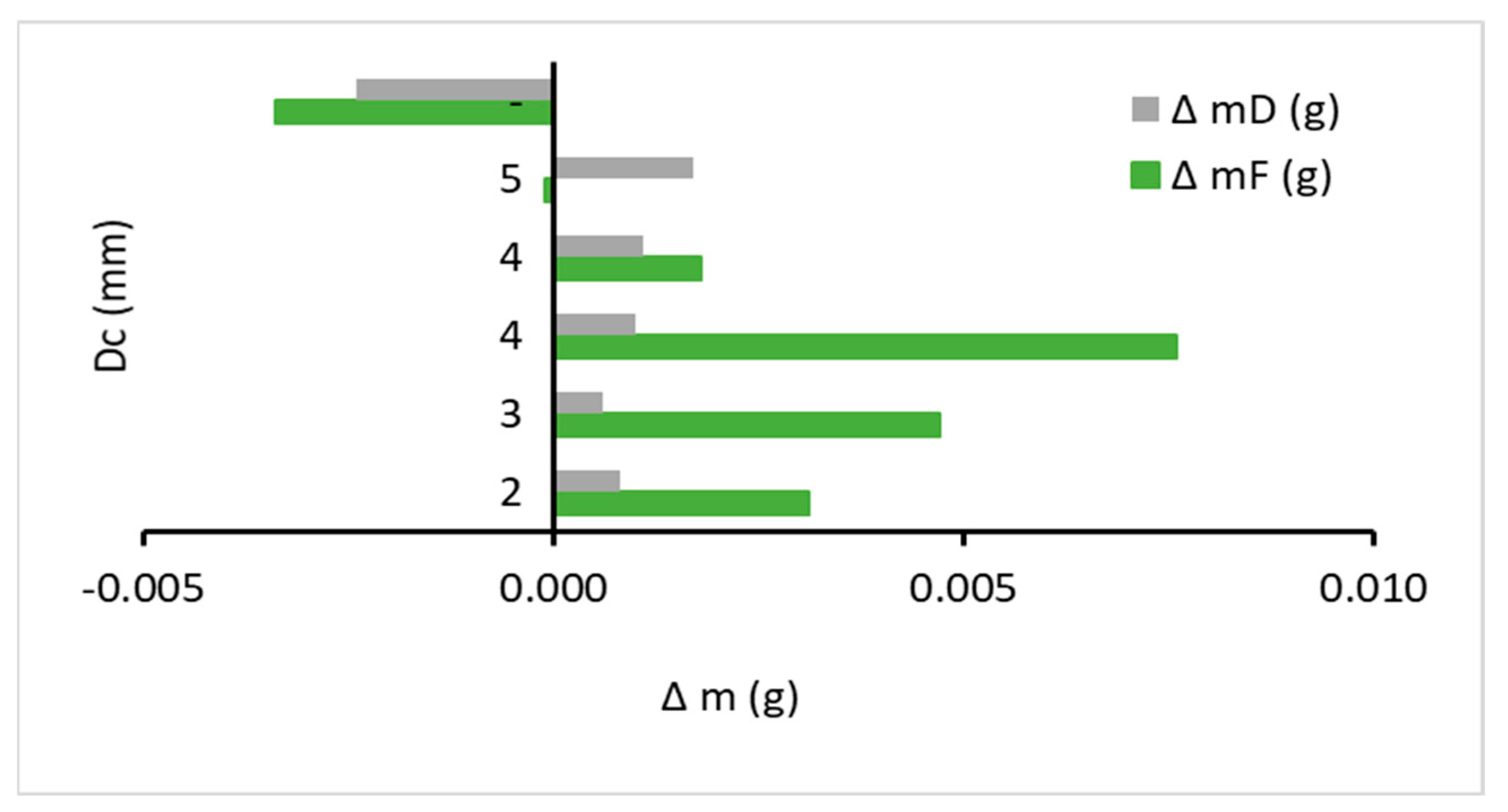
In order to identify which electrode did contribute to the electrochemical reactions and therefore delivered the cells’ current, it was necessary to weigh the electrodes before (m0) and after (mf) each test. Then, the difference in the mass ΔmD = mD0 − mDf (in g) of the Pb-dense lead electrode and ΔmF = mF0 − mFf (in g) of the 25% Sb-Pb ESR foam electrode, calculated from these weighed masses, was plotted for each ESR foam diameter, as shown in Figure 7. The SbPb-dense material (non-porous) was considered, too. If this difference is positive, it means that a loss of mass occurred at the electrode after the test.
It seems that the Pb-dense electrode did not react because its difference in mass ΔmD is constant (0.001 g) for the SbSPb20, SbSPb30, SbSPb35, and SbSPb40, while ΔmF of these foams is positive and changes significantly. This means that these four tested ESR anodes lost some of their mass proportion after running their MFAB cells except for SbSPb 50 (the balance was changed). However, the SbPb-dense electrodes confirmed our claim that in the absence of the open cells of the foams (when the electrode is not porous), this cell inverts and it is the lead electrode (which is inert in the presence of the ESR foam electrodes) that reacts according to the pattern expressed by reactions (1)– ( 3 ).
It looks like these cells are selective: the electrical current is produced from the reactions of the lead carbonates coating the inner surface of the open cells of the ESR foams when they are used. In the absence of these open-cell foams produced by the ESR process, the electrode made of the same alloy as the cell matrix does not react, thus turning the cell into a lead–air battery. It is therefore preferable to use cellular antimonial lead electrodes rather than antimonial lead electrodes in MAB cells.

3.4. FTIR of SbPb-Dense Electrode

In order to confirm the chemical reactivity of the ESR foam electrodes when present in battery cells and then the reactivity of pure Pb-dense electrodes in their absence, Fourier-transform infrared spectroscopy (FTIR) analysis of the external surface of the SbPb-dense sample was performed, before and after an MFAB cell test. This analysis was carried out by using SHIMADZU FTIR–8400 (Shimadzu, Kyoto, Japan) in the range of 4000–400 cm−1.
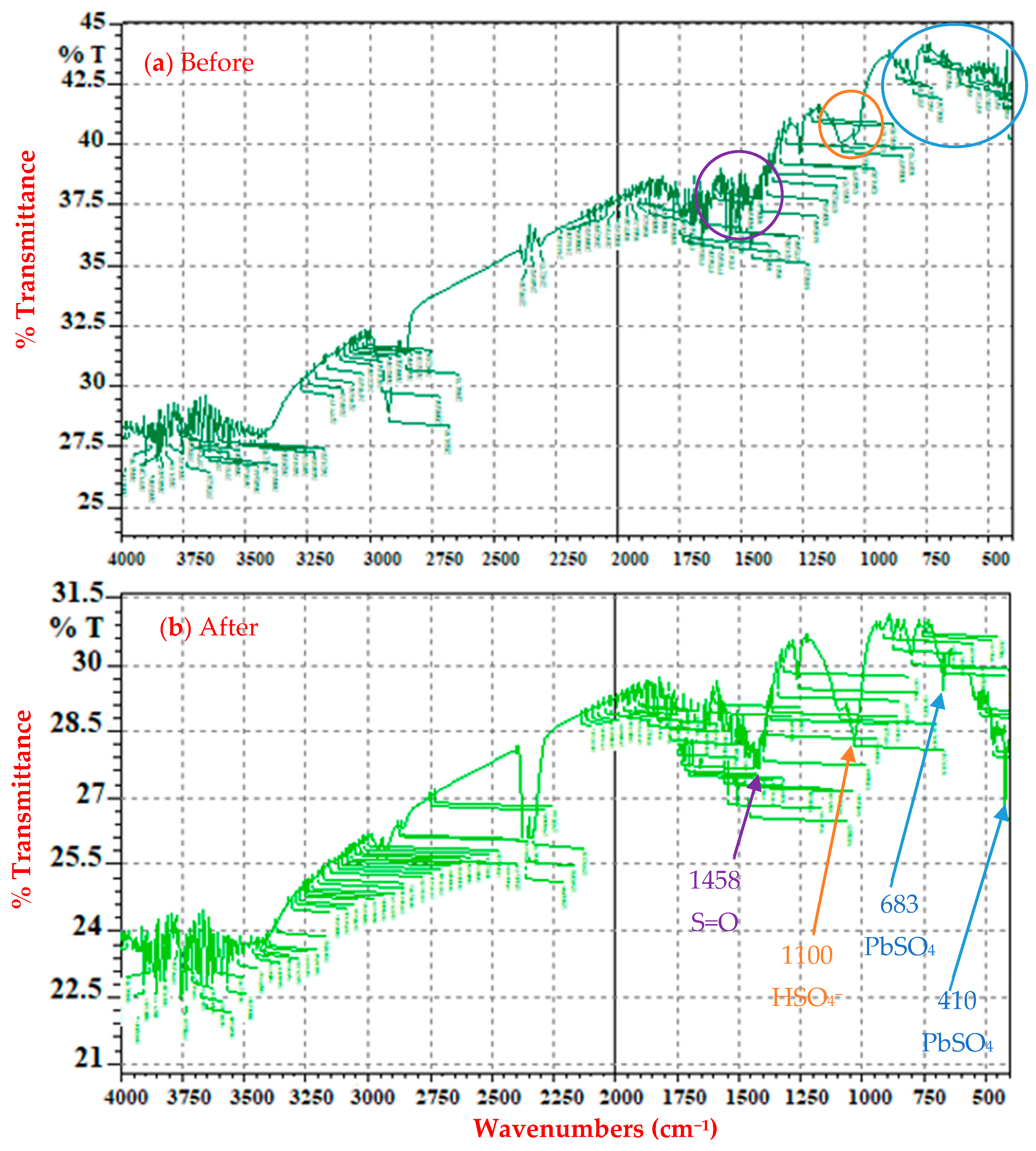
Figure 8 shows the spectra where the significant peaks before the MFAB cell test were found in the regions 1600–1400 cm−1 and 1200–1100 cm−1. There are two broader peaks at wavelength 1419 cm−1 due to the S=O stretching caused by the sulphate group and at 1091 cm−1 due to the hydrogénosulfate (HSO4). This reveals the contribution of the Pb-dense electrode to the electrochemical reaction by detecting the presence of HSO4 and PbSO4 like in lead–air batteries.
After the MFAB cell test, the small peak at wavelength 683 cm−1 and the peak at 410 cm−1 are due to the result of lead sulphate PbSO4 vibration. This PbSO4 was deposited on SbPb-dense electrodes (causing their chemical inertia) after Pb electrode oxidation as an anode. Similarly, another intense and tight peak is found at 2345 cm−1 which is characteristic of CO2. It is the result of some lead carbonate decomposition (from the SbPb-dense electrode) to PbSO4 in the presence of H2SO4. This was confirmed earlier by its ΔmF and the ΔmD of the SbPb-dense cell test.
In spite of all these data, it is difficult to specify the exact electrode reactions occurring during the MFAB cells’ running.

3.5. Effect of Cell Diameter of ESR Foam Anode on Measured Effective Electrical Conductivity

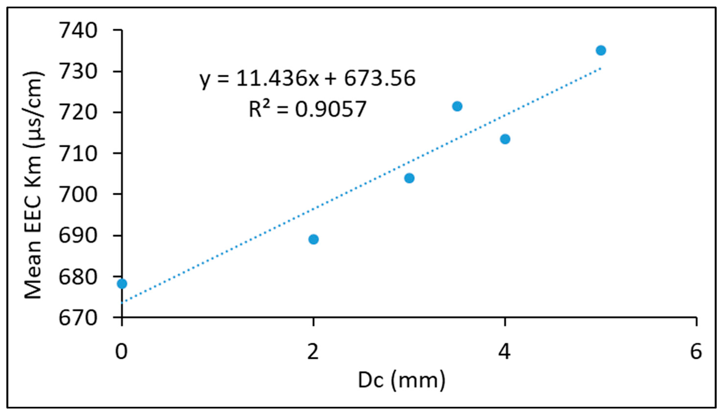
In the replication process, the morphology and pore size are very similar to those of the NaCl particles used. It has already been reported for this type of foam that pore size affects the conductivity of the foam [51]. As stated in this reference, for a fixed porosity, a smaller pore size leads to a lower electrical conductivity, as more air is trapped between the matrix and the NaCl particles, due to the larger interfacial area. A larger pore size leads to a better bonding structure, which results in a higher electrical conductivity, which is in our case effectively represented in Figure 9.
It is clear that a linear relationship exists between the EEC and the cell diameter Dc and that ESR foams performed better than the same non-porous dense alloy as in Equation (6):
K m = 11.44 D c + 673.56
This empirical relationship allows an overall prediction of effective electrical conductivity of future 25% antimony lead alloy foams produced with this ESR process for a specific cell diameter before the elaboration of MFAB cells.

4. Conclusions

Metal–air batteries, powered by metal oxidation and oxygen reduction, have been intensely focused upon as promising next-generation high-energy batteries. In this innovative research on metal–air battery cells, 25% SbPb open-cell foams, with a cell diameter of between 2 mm and 5 mm, have been successfully proposed as an electrode and have performed much better than the non-porous electrode made of the same dense alloy. The large accessible surface area of these open-cell metal foams makes them attractive as electrodes for battery cells with reduced weight. The oxidation of lead carbonate coating on internal cells during the ESR process is believed to be the source of the electrical current of these primary cells.
An empirical relation was proposed to predict the effective electrical conductivity of such foams in terms of cell diameter in lead–air battery cells.
Research is continuing with the aim of producing a final prototype which will be developed and characterised soon. Further improvement of this system could lead to its potential use in the automotive industry.

Author Contributions

Conceptualization, A.H.H.-B., A.-E.B., S.T., H.T., M.K., A.A., D.C., M.Z., A.B. and J.Z.; Data curation, A.H.H.-B. and A.A.; Formal analysis, A.H.H.-B., A.-E.B., S.T., H.T., M.K., A.A., D.C., M.Z. and J.Z.; Investigation, A.H.H.-B., A.-E.B., S.T., H.T., M.K., A.A., D.C., M.Z. and J.Z.; Methodology, A.H.H.-B., A.-E.B., S.T., H.T., M.K., A.A., M.Z. and J.Z.; Project administration, A.-E.B., H.T., A.A. and J.Z.; Resources, A.-E.B., S.T., H.T., A.A., D.C., M.Z. and J.Z.; Software, A.H.H.-B., A.-E.B. and H.T.; Supervision, A.-E.B., A.A. and J.Z.; Validation, A.H.H.-B., A.-E.B., H.T., A.A., D.C., M.Z. and J.Z.; Visualization, A.H.H.-B., A.-E.B., S.T., H.T., M.K., A.A., D.C., A.B., M.Z. and J.Z.; Writing—original draft, A.H.H.-B. and A.-E.B.; Writing—review & editing, S.T., H.T., M.K., A.A., D.C., M.Z. and J.Z. All authors have read and agreed to the published version of the manuscript.

Funding

This research received no external funding.

Data Availability Statement

All relevant data is included within the article.

Conflicts of Interest

The authors declare no conflict of interest.

References

  1. Hossain, M.D.; Islam, M.M.; Hossain, M.J.; Yasmin, S.; Shingho, S.R.; Ananna, N.A.; Mustafa, C.M. Effects of additives on the morphology and stability of PbO2 films electrodeposited on nickel substrate for light weight lead-acid battery application. J. Energy Storage 2020, 27, 101108. [Google Scholar] [CrossRef]
  2. Kaneko, K.; Hori, K.; Noda, S. Nanotubes make battery lighter and safer. Carbon 2020, 167, 596–600. [Google Scholar] [CrossRef]
  3. Wu, F.; Maier, J.; Yu, Y. Guidelines and trends for next-generation rechargeable lithium and lithium-ion batteries. Chem. Soc. Rev. 2020, 49, 1569–1614. [Google Scholar] [CrossRef]
  4. Dunlop, J.; Beauchamp, R. Making space nickel/hydrogen batteries lighter and less expensive. NASA STI/Recon Tech. Rep. N 1987, 88, 13530. [Google Scholar]
  5. Shaffer, B.; Auffhammer, M.; Samaras, C. Make electric vehicles lighter to maximize climate and safety benefits. Nature 2021, 598, 254–256. [Google Scholar] [CrossRef]
  6. Nyholm, L. Lighter and safer. Nat. Energy 2020, 5, 739–740. [Google Scholar] [CrossRef]
  7. Landi, B.J.; Ganter, M.J.; Cress, C.D.; DiLeo, R.A.; Raffaelle, R.P. Carbon nanotubes for lithium ion batteries. Energy Environ. Sci. 2009, 2, 638–654. [Google Scholar] [CrossRef]
  8. Clemente, A.; Costa-Castelló, R. Redox flow batteries: A literature review oriented to automatic control. Energies 2020, 13, 4514. [Google Scholar] [CrossRef]
  9. Linden, D.; Reddy, T. Lead acid batteries. In Handbook of Batteries; U.S. Department of Energy: Office of Scientific and Technical Information: Washington, DC, USA, 2002; pp. 1–88. [Google Scholar]
  10. Logeshkumar, S.; Manoharan, R. Influence of some nanostructured materials additives on the performance of lead acid battery negative electrodes. Electrochim. Acta 2014, 144, 147–153. [Google Scholar] [CrossRef]
  11. Hao, H.; Chen, K.; Liu, H.; Wang, H.; Liu, J.; Yang, K.; Yan, H. A review of the positive electrode additives in lead-acid batteries. Int. J. Electrochem. Sci. 2018, 13, 2329–2340. [Google Scholar] [CrossRef]
  12. Pletcher, D.; Wills, R. A novel flow battery—A lead acid battery based on an electrolyte with soluble lead (II): III. The influence of conditions on battery performance. J. Power Sources 2005, 149, 96–102. [Google Scholar] [CrossRef]
  13. Jullian, E.; Albert, L.; Caillerie, J. New lead alloys for high-performance lead–acid batteries. J. Power Sources 2003, 116, 185–192. [Google Scholar] [CrossRef]
  14. Osório, W.R.; Rosa, D.M.; Garcia, A. The roles of cellular and dendritic microstructural morphologies on the corrosion resistance of Pb–Sb alloys for lead acid battery grids. J. Power Sources 2008, 175, 595–603. [Google Scholar] [CrossRef]
  15. Li, A.; Cheni, Y.; Chen, H.; Shu, D.; Li, W.; Wang, H.; Dou, C.; Zhang, W.; Chen, S. Electrochemical behavior and application of lead–lanthanum alloys for positive grids of lead-acid batteries. J. Power Sources 2009, 189, 1204–1211. [Google Scholar] [CrossRef]
  16. Abdelghani-Idrissi, S. La Charge Rapide D’une Batterie Métal-Air par la Maîtrise de la Fluidique Diphasique. Ph.D. Thesis, Université Paris Sciences et Lettres, Paris, France, 2020. [Google Scholar]
  17. Hariprakash, B.; Mane, A.; Martha, S.; Gaffoor, S.; Shivashankar, S.; Shukla, A. A low-cost, high energy-density lead/acid battery. Electrochem. Solid-State Lett. 2004, 7, A66. [Google Scholar] [CrossRef]
  18. Tabaatabaai, S.; Rahmanifar, M.; Mousavi, S.; Shekofteh, S.; Khonsari, J.; Oweisi, A.; Hejabi, M.; Tabrizi, H.; Shirzadi, S.; Cheraghi, B. Lead-acid batteries with foam grids. J. Power Sources 2006, 158, 879–884. [Google Scholar] [CrossRef]
  19. Bullock, K.R. Lead/acid batteries. J. Power Sources 1994, 51, 1–17. [Google Scholar] [CrossRef]
  20. Martha, S.; Hariprakash, B.; Gaffoor, S.; Trivedi, D.; Shukla, A. A low-cost lead-acid battery with high specific-energy. J. Chem. Sci. 2006, 118, 93–98. [Google Scholar] [CrossRef]
  21. Albert, L.; Chabrol, A.; Torcheux, L.; Steyer, P.; Hilger, J. Improved lead alloys for lead/acid positive grids in electric-vehicle applications. J. Power Sources 1997, 67, 257–265. [Google Scholar] [CrossRef]
  22. Hariprakash, B.; Gaffoor, S. Lead-acid cells with lightweight, corrosion-protected, flexible-graphite grids. J. Power Sources 2007, 173, 565–569. [Google Scholar] [CrossRef]
  23. LaFollette, R.M. Design and performance of high specific power, pulsed discharge, bipolar lead acid batteries. In Proceedings of the Tenth Annual Battery Conference on Applications and Advances, Long Beach, CA, USA, 10–13 January 1995; pp. 43–47. [Google Scholar]
  24. Lach, J.; Wróbel, K.; Wróbel, J.; Podsadni, P.; Czerwiński, A. Applications of carbon in lead-acid batteries: A review. J. Solid State Electrochem. 2019, 23, 693–705. [Google Scholar] [CrossRef]
  25. Liu, Q.; Pan, Z.; Wang, E.; An, L.; Sun, G. Aqueous metal-air batteries: Fundamentals and applications. Energy Storage Mater. 2020, 27, 478–505. [Google Scholar] [CrossRef]
  26. Olabi, A.G.; Sayed, E.T.; Wilberforce, T.; Jamal, A.; Alami, A.H.; Elsaid, K.; Rahman, S.M.A.; Shah, S.K.; Abdelkareem, M.A. Metal-air batteries—A review. Energies 2021, 14, 7373. [Google Scholar] [CrossRef]
  27. Das, S.K.; Lau, S.; Archer, L.A. Sodium–oxygen batteries: A new class of metal–air batteries. J. Mater. Chem. A 2014, 2, 12623–12629. [Google Scholar] [CrossRef]
  28. Rahman, M.A.; Wang, X.; Wen, C. High energy density metal-air batteries: A review. J. Electrochem. Soc. 2013, 160, A1759. [Google Scholar] [CrossRef]
  29. Han, X.; Li, X.; White, J.; Zhong, C.; Deng, Y.; Hu, W.; Ma, T. Metal–air batteries: From static to flow system. Adv. Energy Mater. 2018, 8, 1801396. [Google Scholar] [CrossRef]
  30. Milusheva, Y.; Popov, I.; Shirov, B.; Banov, K.; Boukoureshtlieva, R.; Obretenov, W.; Naidenov, V. Lead-Air Electrochemical System with Acid Electrolyte. J. Electrochem. Soc. 2021, 168, 060524. [Google Scholar] [CrossRef]
  31. Pei, P.; Wang, K.; Ma, Z. Technologies for extending zinc–air battery’s cyclelife: A review. Appl. Energy 2014, 128, 315–324. [Google Scholar] [CrossRef]
  32. Akhtar, N.; Akhtar, W. Prospects, challenges, and latest developments in lithium—Air batteries. Int. J. Energy Res. 2015, 39, 303–316. [Google Scholar] [CrossRef]
  33. Chang, S.; Hou, M.; Xu, B.; Liang, F.; Qiu, X.; Yao, Y.; Qu, T.; Ma, W.; Yang, B.; Dai, Y.J.A.F.M. High-performance quasi-solid-state Na-air battery via gel cathode by confining moisture. Adv. Funct. Mater. 2021, 31, 2011151. [Google Scholar] [CrossRef]
  34. Farsak, M.; Kardaş, G. 2.12 Electrolytic Materials; Dincer, I.B.T.-C.E.S., Ed.; Elsevier: Oxford, UK, 2018; pp. 329–367. [Google Scholar]
  35. Zhao, Y.; Huang, G.; Zhang, C.; Peng, C.; Pan, F. Effect of phosphate and vanadate as electrolyte additives on the performance of Mg-air batteries. Mater. Chem. Phys. 2018, 218, 256–261. [Google Scholar] [CrossRef]
  36. Sumathi, S.; Sethuprakash, V.; Basirun, W.; Zainol, I.; Sookhakian, M. Polyacrylamide-methanesulfonic acid gel polymer electrolytes for tin-air battery. J. Sol-Gel Sci. Technol. 2014, 69, 480–487. [Google Scholar] [CrossRef]
  37. Ashby, M.F.; Evans, T.; Fleck, N.; Hutchinson, J.W.; Wadley, H.N.G.; Gibson, L.J. Metal Foams: A Design Guide; Elsevier Science: Amsterdam, The Netherlands, 2000. [Google Scholar]
  38. Song, M.J.; Kim, I.T.; Kim, Y.B.; Shin, M.W. Self-standing, binder-free electrospun Co3O4/carbon nanofiber composites for non-aqueous Li-air batteries. Electrochim. Acta 2015, 182, 289–296. [Google Scholar] [CrossRef]
  39. Zhu, G.; Li, X.; Liu, Y.; Mao, Y.; Liang, Z.; Ji, Z.; Shen, X.; Sun, J.; Cheng, X.; Mao, J. Scalable surface engineering of commercial metal foams for defect-rich hydroxides towards improved oxygen evolution. J. Mater. Chem. A 2020, 8, 12603–12612. [Google Scholar] [CrossRef]
  40. Wang, H.-F.; Xu, Q. Materials Design for Rechargeable Metal-Air Batteries. Matter 2019, 1, 565–595. [Google Scholar] [CrossRef]
  41. Hassein-Bey, A.H.; Belhadj, A.-E.; Gavrus, A.; Abudura, S. Elaboration and Mechanical-Electrochemical Characterisation of Open Cell Antimonial-lead Foams Made by the “Excess Salt Replication Method” for Eventual Applications in Lead-acid Batteries Manufacturing. Kem. U Ind. Časopis Kemičara I Kem. Inženjera Hrvat. 2020, 69, 387–398. [Google Scholar] [CrossRef]
  42. Prengaman, R.D. SECONDARY BATTERIES—LEAD—ACID SYSTEMS|Lead Alloys. In Encyclopedia of Electrochemical Power Sources; Garche, J., Ed.; Elsevier: Amsterdam, The Netherlands, 2009; pp. 648–654. [Google Scholar]
  43. Hill, R.J. Structure of PbSb2O6 and its relationship to the crystal chemistry of PbO2 in antimonial lead-acid batteries. J. Solid State Chem. 1987, 71, 12–18. [Google Scholar] [CrossRef]
  44. Dharmasena, K.; Wadley, H. Electrical conductivity of open-cell metal foams. J. Mater. Res. 2002, 17, 625–631. [Google Scholar] [CrossRef]
  45. Ashby, M.F.; Evans, A.G.; Fleck, N.A.; Gibson, L.J.; Hutchinson, J.W.; Wadley, H.N.G. Metal Foams: A Design Guide; Butterworth-Heinemann: Oxford, UK, 2000; p. 263. [Google Scholar]
  46. Liu, P.; Li, T.; Fu, C. Relationship between electrical resistivity and porosity for porous metals. Mater. Sci. Eng. A 1999, 268, 208–215. [Google Scholar] [CrossRef]
  47. Majima, H.; Peters, E.; Awakura, Y.; Park, S.K. Electrical conductivity of acidic sulfate solution. Metall. Trans. B 1987, 18, 41–47. [Google Scholar] [CrossRef]
  48. BIAGETTI, R. Fabrication of Lead-Acid Batteries. U.S. Patent No. 3,765,943, 16 October 1973. [Google Scholar]
  49. Newman, J.; Tiedemann, W. Porous-electrode theory with battery applications. AIChE J. 1975, 21, 25–41. [Google Scholar] [CrossRef]
  50. Mai, T.T.T.; Phan, T.B.; Pham, T.T.; Vu, H.H. Nanostructured PbO2-PANi composite materials for electrocatalytic oxidation of methanol in acidic sulfuric medium. Adv. Nat. Sci. Nanosci. Nanotechnol. 2014, 5, 025004. [Google Scholar] [CrossRef]
  51. Ma, X.; Peyton, A.; Zhao, Y. Measurement of the electrical conductivity of open-celled aluminium foam using non-contact eddy current techniques. NDT E Int. 2005, 38, 359–367. [Google Scholar]
Figure 1. Experimental stand showing the test cell of the 25% SbPb–air battery.
Designs 08 00061 g001
Figure 2. Effective electrical conductivity of SbSPb20, SbSPb30, and SbSPb35 cells.
Designs 08 00061 g002
Figure 3. Effective electrical conductivity of SbSPb40, SbSPb50, and SbPb-dense cells.
Designs 08 00061 g003
Figure 4. Comparison of effective electrical conductivity.
Designs 08 00061 g004
Figure 5. A magnification of the film existing between the salt grain and antimonial lead alloy matrix in the SbS40 ESR foam sample obtained with JOEL JSM-6360 before NaCl leaching. The chemical composition of the different species present was revealed with EDXS.
Designs 08 00061 g005
Figure 6. EDXS of SbS40 revealing chemical composition of cell matrix and inner cell wall after salt leaching.
Designs 08 00061 g006
Figure 7. An analysis of the difference in mass ΔmD of the Pb-dense lead electrode and ΔmF of the 25% SbPb ESR foam electrode.
Designs 08 00061 g007
Figure 8. FTIR spectra of SbPb-dense electrode (a) before and (b) after MFAB.
Designs 08 00061 g008
Figure 9. Linear relationship between effective electrical conductivity and cell diameter of MFAB.
Designs 08 00061 g009
Table 1. Measured and calculated parameters of all tested cells.
mF0 (g)mD0 (g)mFf (g)mDf (g)ΔmF (g)ΔmD (g)Dc (mm)P (%)T0–Tf (°C)Km (µS/cm)pH0–pHf
sbspb20 5.7803.6965.7773.6950.0030.0012.0004619.6–19.7689.001.16–1.18
sbspb302.3503.6642.3453.6630.0050.0013.0006617.9–17.5704.051.25–1.29
sbspb35 6.3113.3746.3033.3730.0080.0013.5004819.7–19.9721.421.11–1.13
sbspb408.0683.7528.0663.7500.0020.0014.0005617.8–17.7713.531.13–1.11
sbspb503.4583.7343.4583.7320.0000.0025.0006017–16.7735.161.25–1.26
sbpb-dense3.6953.8693.6983.871−0.003−0.002-017.3678.361.15–1.17
Disclaimer/Publisher’s Note: The statements, opinions and data contained in all publications are solely those of the individual author(s) and contributor(s) and not of MDPI and/or the editor(s). MDPI and/or the editor(s) disclaim responsibility for any injury to people or property resulting from any ideas, methods, instructions or products referred to in the content.