1. Introduction
Speech communication is an integral part of our daily life. During speech production, a speaker encodes information into a continuously time-varying wave propagated through a medium [
1]. The wave propagates from a speaker to a listener through the vibration of air particles. Finally, a listener perceives the information contained in the sound wave.
The human peripheral auditory system is one of the most critical components of speech perception. The human peripheral auditory system consists of three major parts [
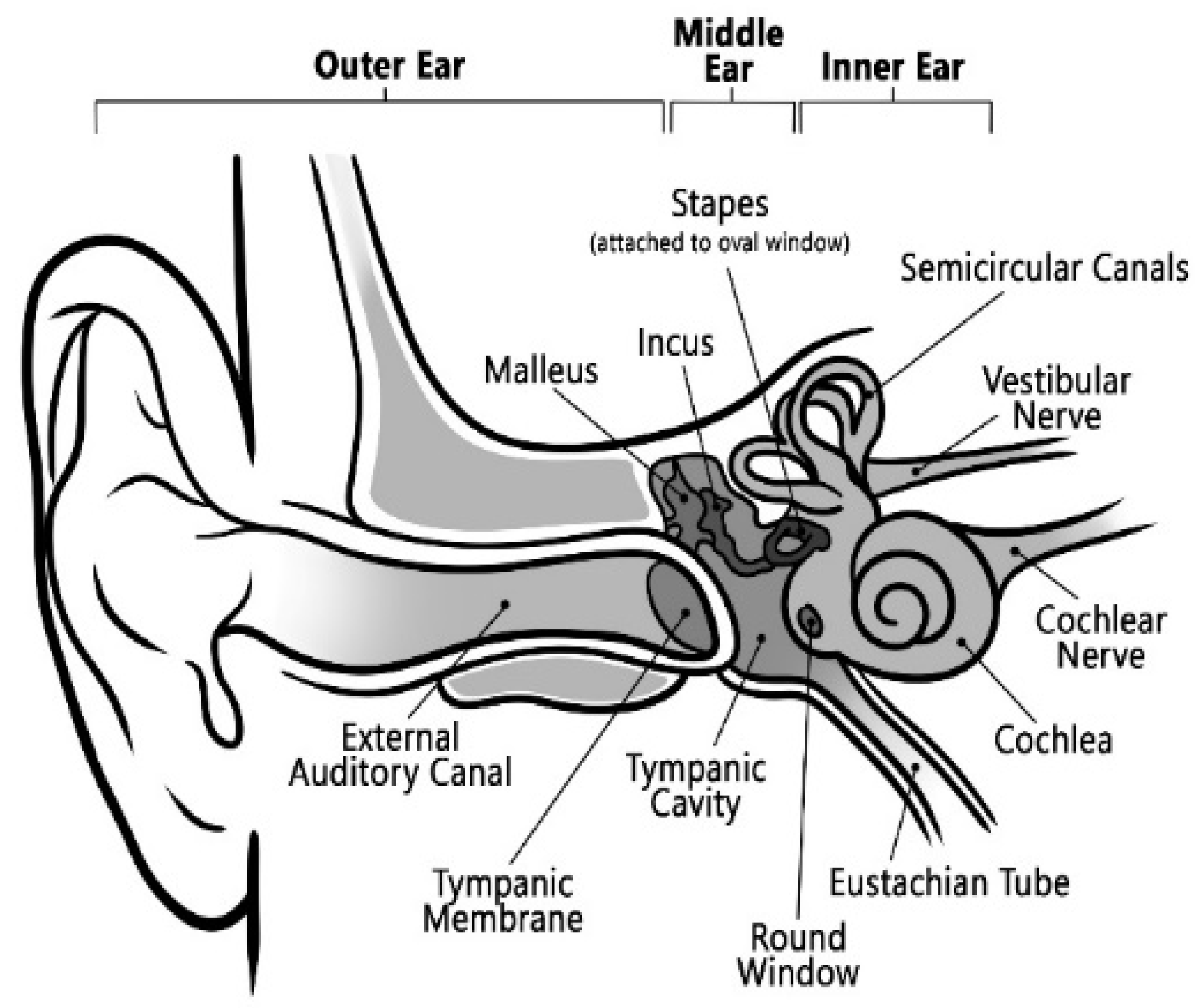
2]: the outer, middle, and inner ears, as shown in
Figure 1. Sound enters the outer ear through the pinna, travels down to the auditory canal, and vibrates the eardrum. The middle ear, consisting of three bones, transports the vibration of the eardrum to the inner ear. The main component of the inner ear is the snail-shaped cochlea, a coiled tube filled with fluid [
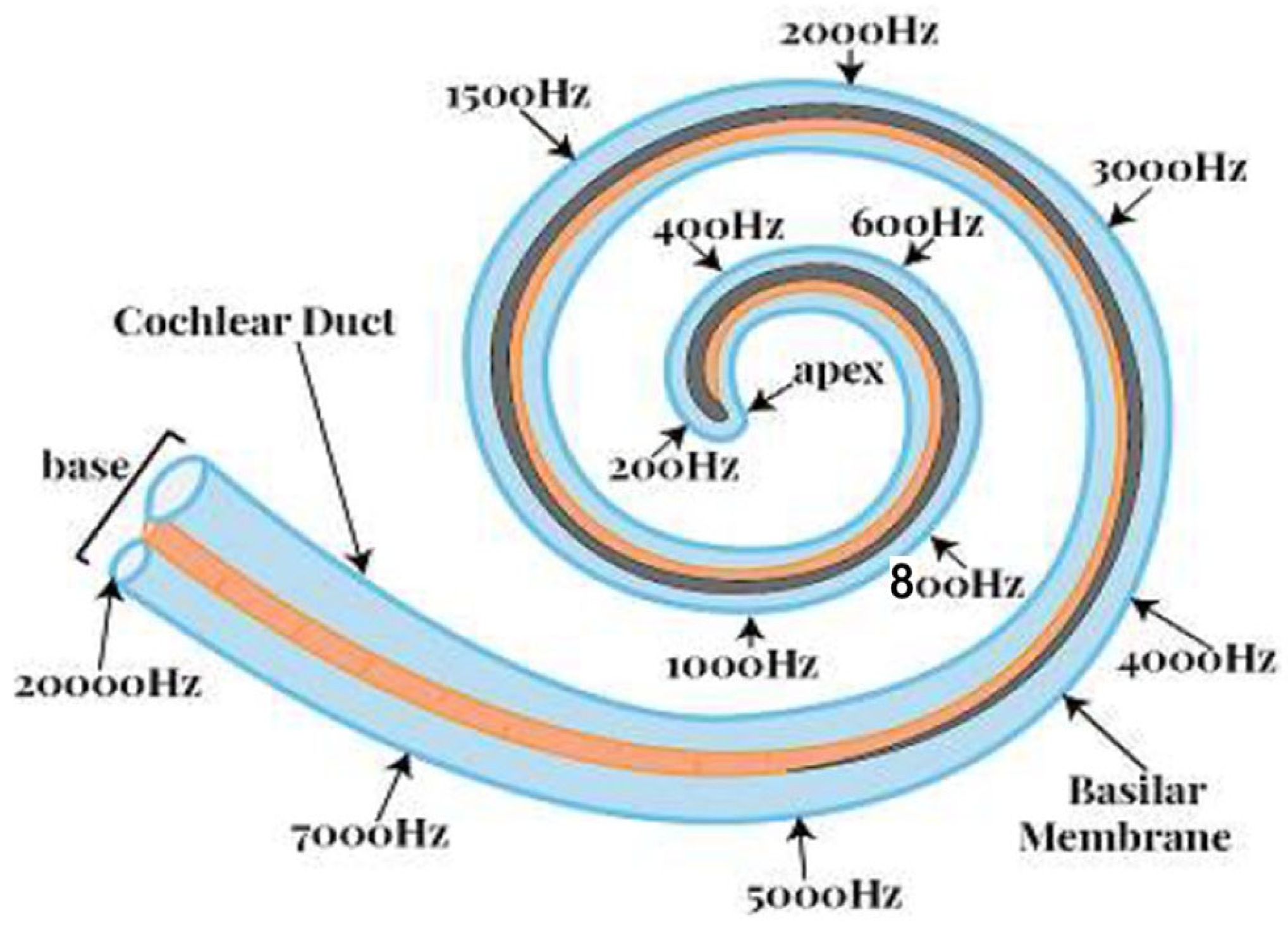
3]. Within the cochlear fluid, there exists a basilar membrane. The sound vibration at the eardrum ultimately generates a compressed sound wave in the cochlear fluid and causes a vertical vibration in the basilar membrane. The basilar membrane is mechanically tuned at different frequencies. It plays a vital role in distributing sound energy in frequencies along the cochlea’s length, as shown in
Figure 2. The wavelengths of audible sound can cover a wide range of scales. As depicted in this figure, the lower frequencies are located near the ‘apex’. In contrast, the higher frequencies are at the far end, called ‘base’. The low-frequency waves can have wavelengths of up to 17 m (20 Hz), while the highest frequencies can be as small as 1.7 cm (20,000 Hz).
In conjunction with the basilar membrane, the hair cells translate mechanical information into neural information. If the hair cells are damaged, the auditory system cannot transform sound into neural impulses. The sound never reaches the brain because of the damaged hair cells. Many causes can damage hair cells, including diseases, congenital disorders, and specific drug treatments. Damaged hair cells can degenerate adjacent auditory neurons, too. Damaged neurons and hair cells can make a person profoundly deaf. However, recent research [
5] has shown that the most common cause of deafness is the loss of hair cells rather than the loss of auditory neurons.
Hearing loss is the third most common health problem affecting the elderly population after heart disease and arthritis, according to some statistics [
6]. Hair cells can be damaged over time, being open to continuous mechanical stress from environmental issues, including sounds. Various factors, e.g., aging, genetic defects, and ototoxic drugs, also cause additional risks of cell damage [
7]. This damage can be mild to severe, causing even the death of hair cells. Unfortunately, human hair cells do not regenerate. The repair of hair cells is crucial for continued auditory function throughout life. Clinicians recommend several drugs to restore the proper functioning of hair cells when the damage is minor. Sudden hearing loss resulting from viral infection is medically treated with corticosteroids. Corticosteroids may also be used to reduce cochlear hair cell swelling and inflammation when exposed to loud noise. However, clinical restoration of damaged hair cells from aging and genetic causes remains a research issue. Recently, gene therapy has been proven effective in restoring the functionality of damaged hair cells due to genetic factors in several animal models [
8]. Even the perceptual quality of voice signals is greatly affected by hearing mechanisms [
9]. A degraded voice can, in turn, be a biomarker of a human’s health status, including both structural and neurological malfunctions in speech and hearing mechanisms [
10,
11,
12,
13].
A cochlear implant can play an important role here as it can excite the neurons through electrical stimulation to restore the hearing ability of a deaf person. The main idea is bypassing the standard hearing mechanism and electrically stimulating the auditory neurons.
Researchers have proved that frequency analysis performed concerning the cochlea can be modeled as a bandpass filter bank. Various filters have been proposed to implement bandpass filter banks. One of the earliest proposed filters is the rounded exponential function (‘roex’) [
14]. The authors have shown that an exponential function can represent the auditory filter shape successfully. A novel reverse correlation technique has been introduced to better model the auditory filter [
15]. Another function called ‘revcor’ has been introduced to define the impulse response of the peripheral auditory filters. Peculiarly, this function provides the impulse response of a sharp bandpass filter. Consequently, the GTF has been introduced in [
16] to provide an analytic mathematical function approximating the ‘revcor’ function. Other researchers have further developed the GTF to make it suitable for practical design purposes [
17,
18]. One of the main merits of the GTF is its convenient mathematical form. Hence, its properties can be easily derived analytically compared to similar filters, including ‘roex’ filters. One of the pioneering works that investigated various properties of the GTF has been presented in [
19]. The authors have defined the GTF as an infinite impulse response (IIR) filter in the time domain and described its provenance and some of its elementary properties. They also examined the behavior of the GTF in the frequency domain. They provided a way of calculating the parameters needed for a GTF to have a specified ERB. The authors provided an efficient digital implementation of the GTF on a general-purpose computer. A digital multiple-pass IIR filter technique has also been proposed to implement the GTF [
20] for practical designs.
Recently, the GTF has drawn researchers’ attention to sound event detection, speech signal processing, voice pathology detection, and speech recognition. In [
21], the authors have proposed a GTF-based automatic speech recognition (ASR) technique. They demonstrated that GTFs are promising in terms of improving the robustness of ASR systems against noise compared to the Mel-Frequency Cepstral Coefficient (MFCC) and Perceptual Linear Prediction (PLP). GTF-based parametric filter banks have been proposed in [
22] to detect speech. Three filter banks based on Mel, Gammatone, and Gaussian filters have been investigated in that work. The comparative investigation showed that the GTFs provided the highest speech detection accuracy compared to the Gaussian and Mel filters. A GTF-based sound event detection and localization (SEDL) system has been presented in [
23]. The authors demonstrated that GTFs could boost the performance of state-of-the-art SEDL algorithms. In [
24], the authors have applied the GTF to produce an image representation of sound signals for audio surveillance. They called this image representation a Cochleagram. The authors have shown that the proposed Cochleagram provided more noise robustness than cepstral features, namely Mel-Frequency Cepstral Coefficients and the spectrogram image feature (SIF). A learnable GTF bank is proposed to classify environmental sounds in [
25]. The authors demonstrated that the learnable filter parameters of the GTFs could preserve the spectro-temporal domain features of environmental sound and can achieve high classification accuracy. In [
26], the authors have shown that the GTF could enhance the performance of hearing aids. They concluded that the GTFs could provide a high hearing aid speech quality index (HASQI). A GTF-based speaker recognition system has been proposed in [
27]. The authors have argued that conventional speaker recognition systems perform poorly under noisy conditions. They introduced a novel spectral feature called the Gammatone frequency cepstral coefficient (GFCC). They showed that this feature captured speaker characteristics and performed substantially better than conventional spectral features under noisy conditions. The results showed significant performance improvements over related systems under a wide range of signal-to-noise ratios. In [
28], the performances of the cochlear implants (CIs) have been investigated by using three different filters, namely GTF, DAPGF (Differentiated All-Pole GTF), OZGF (One-Zero GTF) and BUTF (Butterworth). Filter parameters, including the filter order (
), the filter quality factor (
), and the number of channels (
) and their combinations, were tested using objective and subjective metrics in that work. The simulation results concluded that the
and
parameters are crucial for designing cochlear implants.
Although the GTF has attracted considerable attention from researchers, as mentioned above, a comprehensive exposition on the GTF is still absent in the literature other than the work presented in [
29]. That work has provided a tutorial introduction to the GTF without much detail. The main goals of this investigation are as follows:
Explore the effects of filter parameters: order , carrier frequency , carrier phase , temporal decay coefficient , and Gammatone distribution function , on the impulse response of the GTF.
Derive the transfer function of the GTF from the definition of the by using the Fourier transform and its properties.
Investigate the effects of the above filter parameters on the transfer function of the GTF.
Derive the expression for ERB of the GTF.
Design a filter bank using the GTF for a given pseudo-resonant .
Demonstrate the application of the GTF in cochlear implant design.
The structure of this investigation is organized as follows:
Section 2 explains the impulse response and spectrum of GTFs.
Section 3 elaborates on the ERBs.
Section 4 describes the possible application of GTFs in cochlear implant design.
Section 5 addresses some underlying design issues and challenges. Finally, the paper concludes with a synopsis of key findings and explores possible routes for future research.
2. Impulse Response and Spectrum of GTFs
In [
30], a Gammatone function has been used to model the basilar membrane displacement in the human ear. It has been further investigated, and it was shown that a GTF can be used to approximate responses recorded from the cochlear nucleus in cats [
16]. In a similar work [
31], a Gammatone function was used to model the impulse responses based on the auditory nerve fiber recordings in cats. Finally, the term “Gammatone filter” was introduced in [
32], and its impulse response was defined as follows:
where
is the proportionality constant,
is the filter order,
the temporal decay constant,
is the carrier frequency,
is the carrier phase, and
is the unit step function. The expression of
can be broken down into two components, namely the carrier component and the Gamma distribution function.
Let us assume that the carrier component is denoted by
and the Gammatone distribution function is defined by
Hence, the impulse response of the GTF can be expressed as
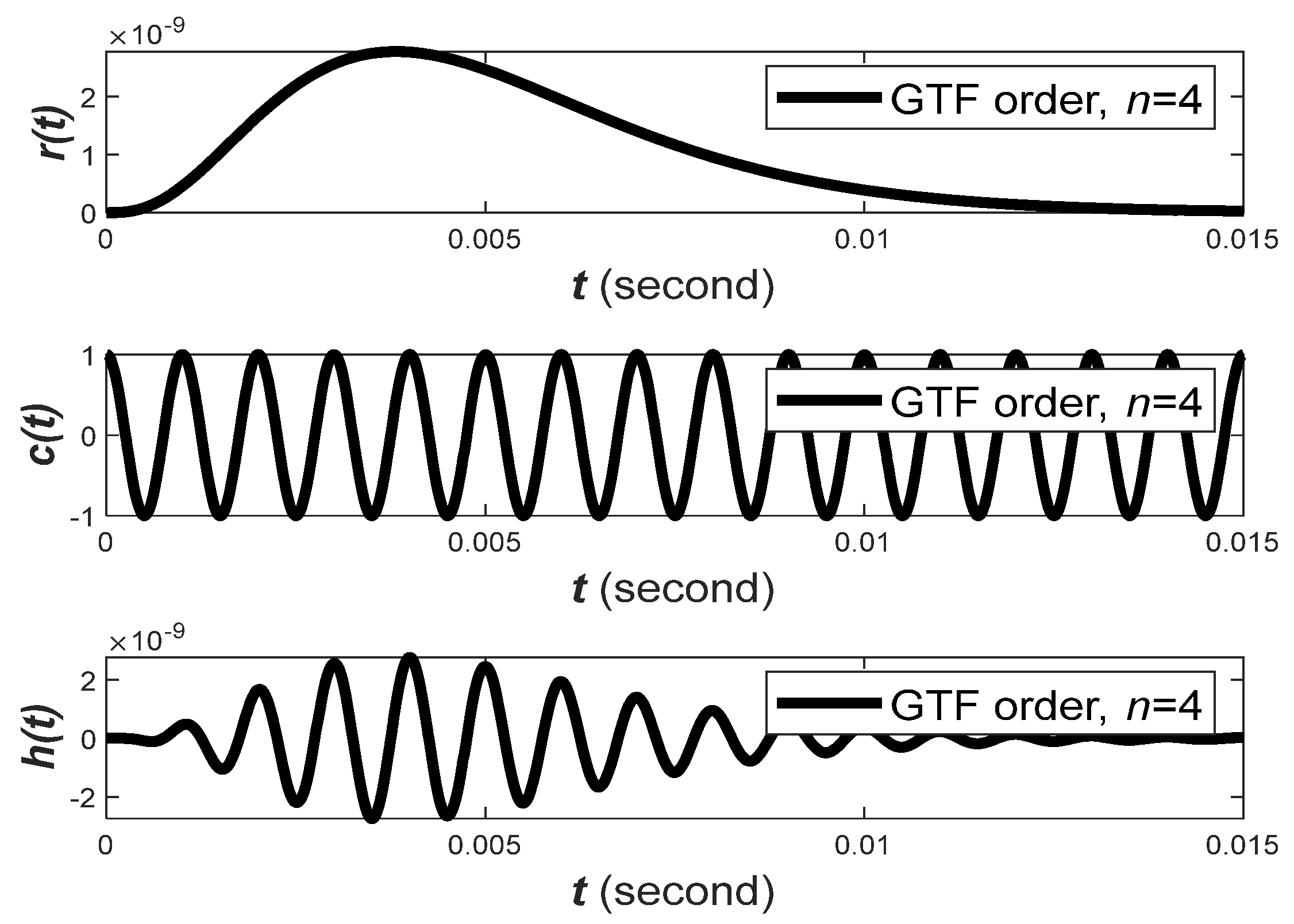
Figure 3 shows the plot for
of the GTF with its constituent components. In the plot, factor
has been set to
to make the integration under the curve of Gamma distribution equal to one. The other parameters are arbitrarily set to
, and
Hz. The filter order
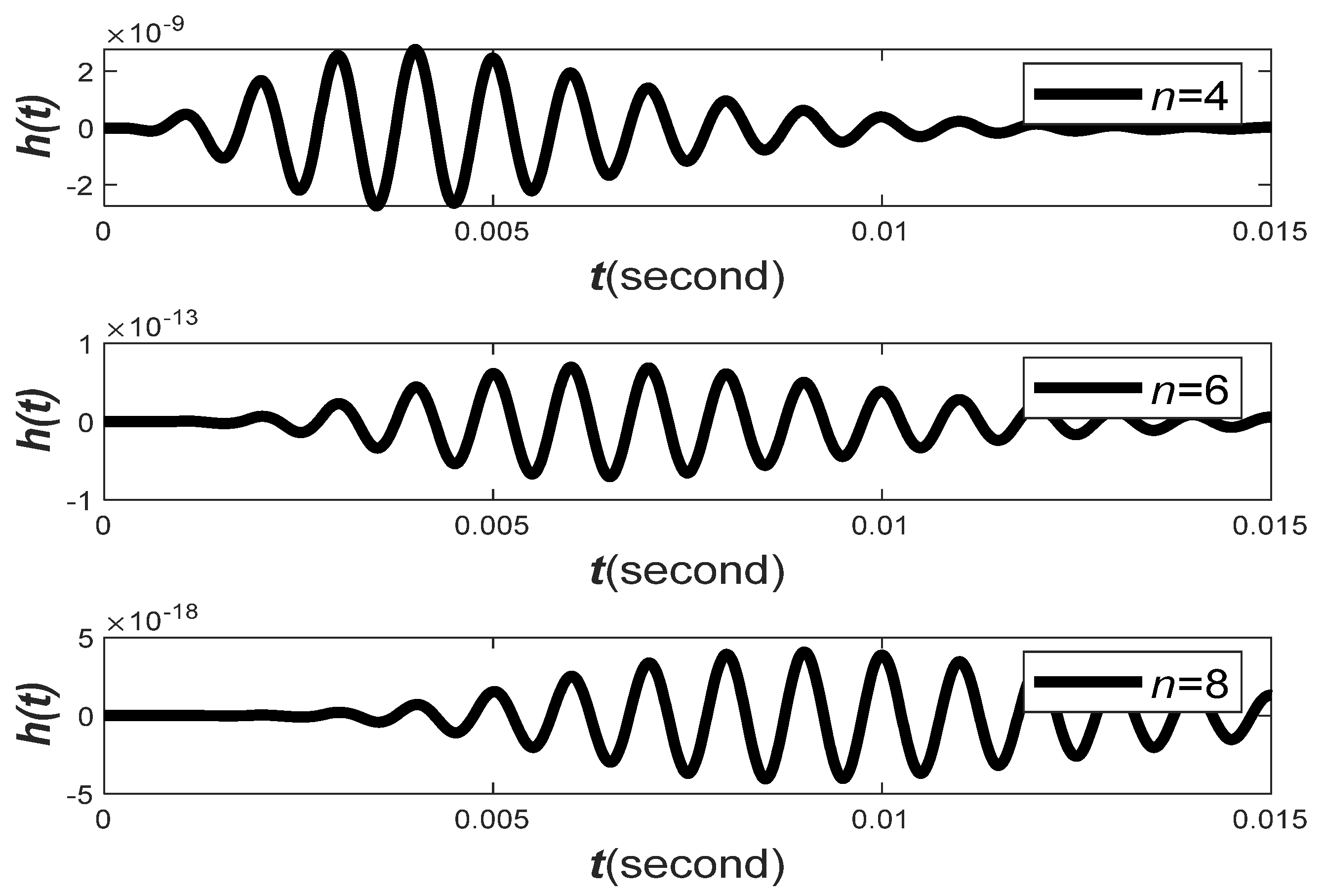
of a GTF is an important design parameter. It controls the relative shape of the filter impulse response, as demonstrated in
Figure 4. The relative shape becomes less skewed as the filter order
increases. The carrier phase,
is also an important property that determines the relative position of the envelope.
Observation 1. When the filter order is higher, the impulse response of the GTF becomes less skewed and vice versa.
The Fourier transform of the GTF’s impulse response
will be derived to investigate its frequency domain behaviors. From the convolution property of the Fourier transform, we know that if
, then
(
Appendix A). By applying this property to (4), we can express
as
where
is the Fourier transform of
,
is the Fourier transform of
, and
is the Fourier transform of
. We can find the Fourier transform of
by using the Fourier transform identity,
(
Appendix B). Substituting
, we can find the Fourier transform of
as
From the property of the Fourier transform (
Appendix A), we also know that if
By substituting
, we can express the Fourier transform of
as
If we substitute
in (7), we can find
. Similarly, if we substitute
, we can find,
. Proceeding in the same way, we can find the Fourier transform of
as
The Fourier transform of
can be alternatively expressed as
Now, let us find the Fourier transform of the carrier signal,
. The carrier signal is given by
, which can be alternatively expressed as
. By using the Fourier transform identities
, and
, the Fourier transform of
can be expressed as
Substituting the Fourier transform of
and
in (5), we can determine the expression of
H(
f) as
By using the convolutional property of the delta Dirac function (
Appendix C),
We can find the final expression of the
as
The plots for the
and
are shown in
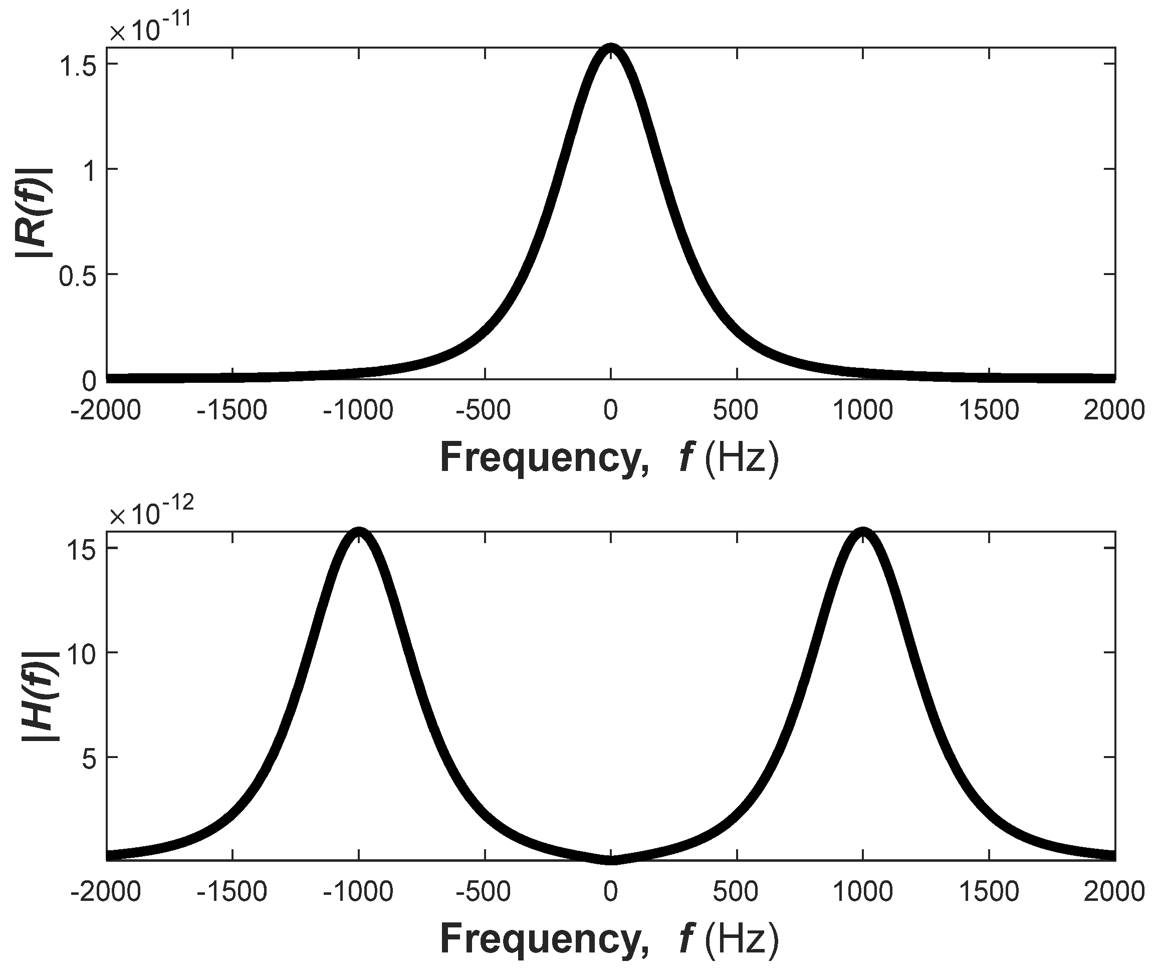
Figure 5. This figure shows that the
produces two copies of the
separated by the two times the carrier frequency,
fc.
Observation 2. The Fourier transform of the Gamma distribution component of the GTF impulse response has one maximum value at Hz. However, the Fourier transform of the impulse response has two maxima, and the location of these two maxima depends on the carrier frequency. To avoid interference, these two frequency components shall be sufficiently separated by selecting a high carrier frequency.
The Fourier transform of
can be expressed in terms of the Fourier transform of
. From (5), we can write
where
is given by (9) and can be alternatively expressed as
The expression of
can be further simplified by assuming
Replacing
with
, we can modify (18) as
Then, we can express
as
The impulse response of the GTFs and their transfer functions are plotted in
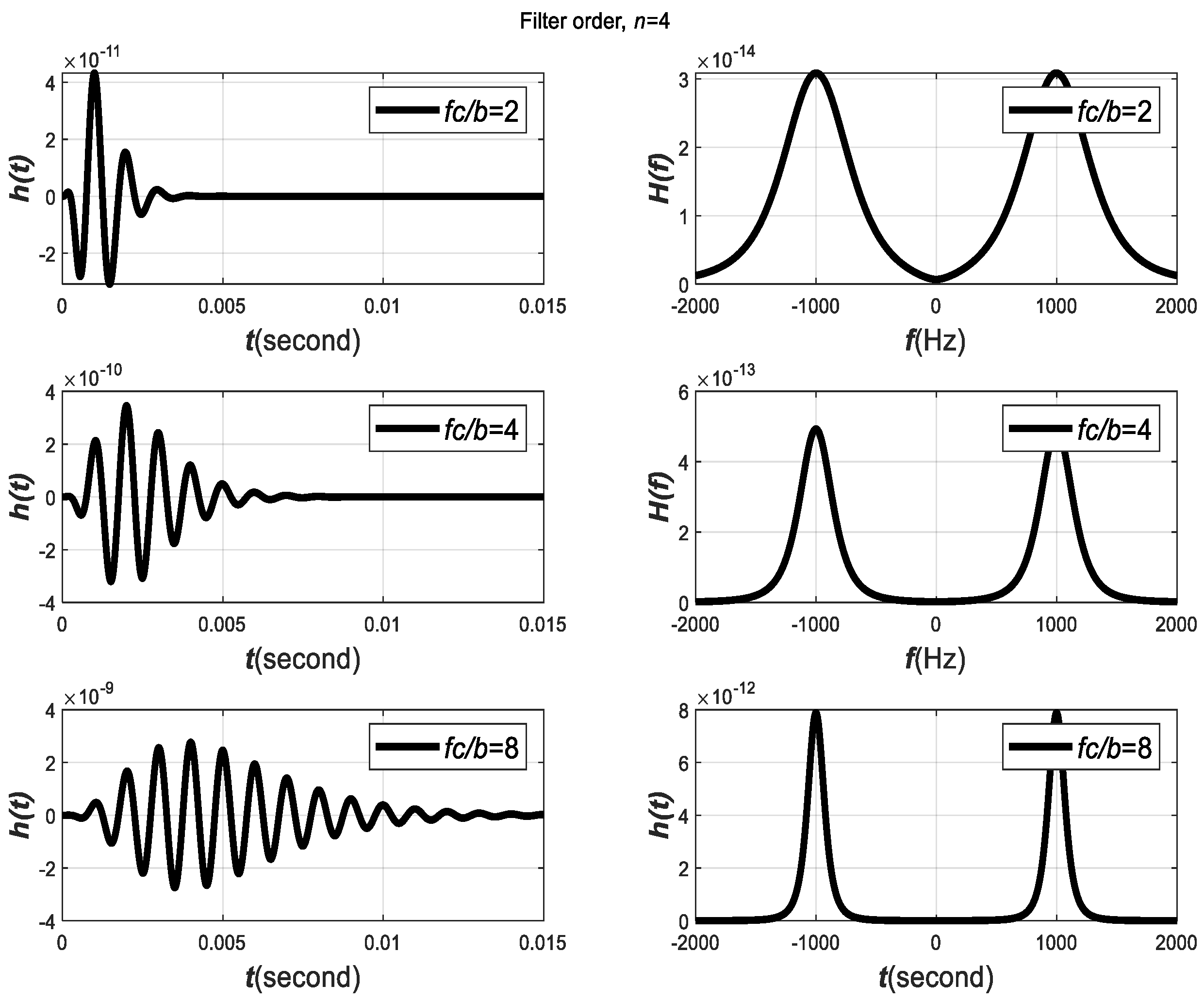
Figure 6 for varying parameters of
. The figure shows that,
is another critical parameter that affects the decaying behavior of the filter impulse response and filter transfer function.
Observation 3. When is small (i.e.,
is large),
will decay slowly. On the other hand,
will decay more rapidly and vice versa.
Observation 4. The larger the ratio , the less the components of
and
overlap, and less interference between
and
will occur.
In general,
can be expressed in terms of magnitude and phase spectrum as
, where
is the magnitude of
, and
= phase spectrum of
. The power spectrum of
is expressed by
By using the Fourier transform property (
Appendix B), we can simplify the following expressions as
and
. Hence,
and
can be expressed as
Assume
. The
can be expressed in terms of magnitude and phase as
, where the magnitude is defined by
, and the phase spectrum is defined by
, now,
can be expressed in terms of
, as
Substituting
with
, we can find the expression of
as
. Now,
can be expressed in terms of magnitude and phase as follows
, where the magnitude of
is defined as
, and the phase
. Now,
can be expressed in terms of
as
We can express the terms presented in (22) as follows
Let us find the expression of
by
The expression of can be expressed in terms of magnitude and phase as , where the magnitude can be expressed as
and
. Hence,
can be expressed as
Taking the real part of
, we can write
Substituting all the derived terms in (22) we write the final expression of the power spectrum as
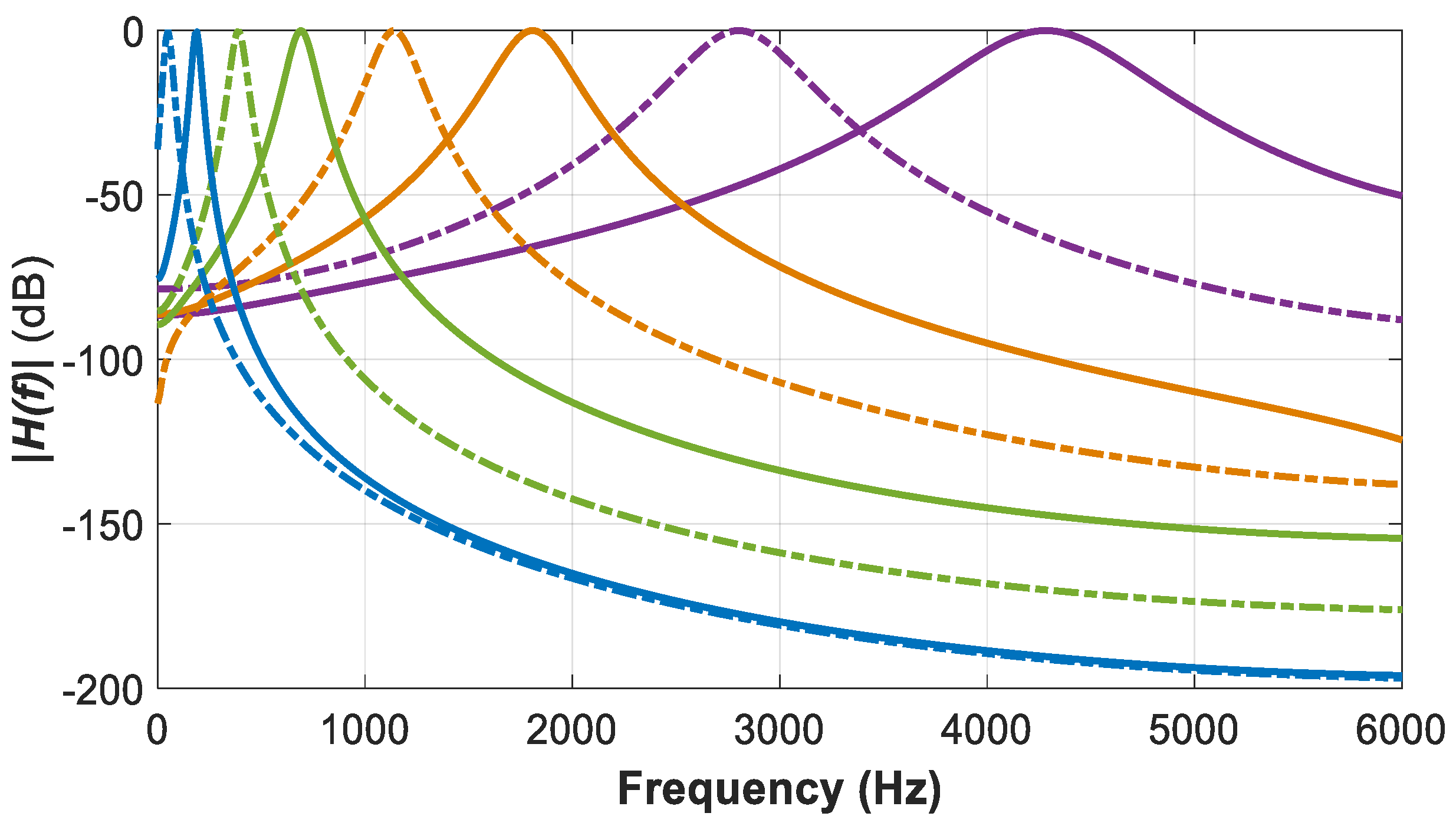
The power spectrum,
is plotted in
Figure 7 for varying
. Based on the expression of
in (32) and the plot in
Figure 7, we can make the following observations:
Observation 5. When
is small,
will decay slowly; however, will decay more rapidly.
Observation 6. Although
and
have their maximum at
, the power spectrum
does not necessarily have a maximum at
Hz.
Observation 7. When
and
overlap significantly for small
,
has the character of a low pass filter with the peak at the origin.
Observation 8. As
is increased (for fixed order), the single peak splits and the maxima move outwards and eventually converges to
.
Figure 7.
The plot of the power spectrum of the GTF, with varying for n = 2. The plot shows that the power spectrum decays rapidly with a higher value of . This faster decay reduces the interference between the frequency components of the GTF.
Figure 7.
The plot of the power spectrum of the GTF, with varying for n = 2. The plot shows that the power spectrum decays rapidly with a higher value of . This faster decay reduces the interference between the frequency components of the GTF.
Since the purpose of the GTF in auditory modeling is to model a bandpass filter, the components
and
must be well separated, and it is required to make
large enough. In this case, we can simplify the expression of
H(
f) as
In addition,
. The power spectrum expressed in (32) will be simplified as
For large
, the carrier phase
does not have any effect on the maximum value of the power spectrum. For small
, the carrier phase
influences where the maximum power spectrum occurs. Holdsworth shows that the optimum range of
should be
for auditory modeling [
15].
3. Equivalent Rectangular Bandwidth (ERB)
The ERB is a measure commonly used in psychoacoustics that approximates the bandwidth of the filters in human hearing. The ERB of a filter
is typically defined as the width of a rectangular filter whose height equals the maximum of the power spectrum of
and possesses the same amount of power. Based on this definition, the rectangular bandwidth
can be expressed as
where
is the maximum value of the power spectrum, which occurs at
. By using Perseval’s theorem, the energy of a signal,
can be expressed as
Hence, the expression of the rectangular bandwidth can be expressed as
Let us assume
; hence,
can be expressed as
From the definition of the Fourier transform of
, we can write
The dc component of
can be found by substituting
in (43) and can be expressed as
By substituting
by
in (39), we can find an alternative expression for the equivalent rectangular bandwidth,
as
Squaring the (4), we can find the expression of
as
This expression can be further simplified as
where
and
By taking the Fourier transform of both sides of (47) and applying the convolution property of the Fourier transform, we can write
where
= Fourier transform of
, and
= Fourier transform of
. Now, we need to find the Fourier transform of
and
and substitute in (50). Applying the Fourier transform property
. Substituting
, and
, we can find the
. This expression can be further simplified as
Now, the expression of
can be simplified as
Taking the Fourier transform, we can express the Fourier transform of
as
Substituting the value of
and
in (50), we find the expression of
as
By using the convolution property of the delta dirac function, the above expression can be further simplified as
By substituting
, we can find the expression of
as
Let us assume
and
. We can express
as
Similarly, it can be proved that
can be expressed as
where
. However,
. Hence,
can be expressed as
By using the complex variable identity
. We can write the expression of
as
Substituting
in (32) we can find the expression of
as
Substituting
and
in (45), we can find the final expression of the
as
According to the definition of the
, we substitute
in (59) and can find the final expression of
as
Defining two more design parameters
η and
μ as
Substituting
(61), we can find the final expression for
η as
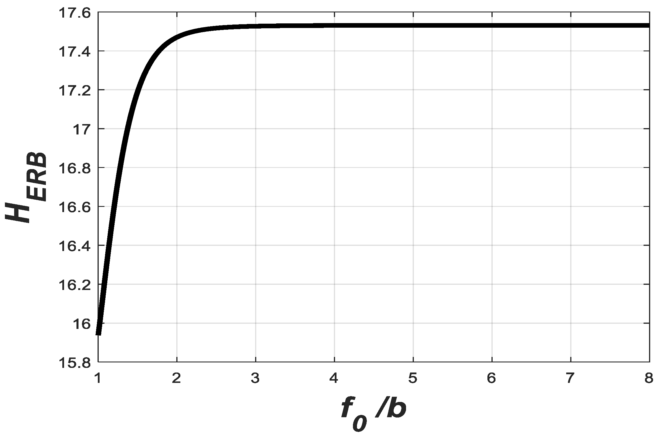
The variation in
with
is plotted in
Figure 8. The maximum value of
is
when
is sufficiently large. With this value of
,
becomes approximately
Hence, becomes proportional to and independent of . As mentioned above, the resonant frequencies along the basilar membrane vary from 20 Hz at the apex to 20,000 Hz at the base. Hence, it is essential to make the bandwidth of the filter independent of the carrier frequency, . This makes the GTF a unique candidate for auditory modeling in cochlear implants.
4. Application of GTFs in Cochlear Implant Design
Almost 40 years ago, researchers initiated the restoration of normal hearing in deaf people via electrical stimulation of the auditory nerve [
33]. Since then, they have been investigating different techniques for delivering electrical stimuli to the auditory nerve so that profoundly deaf people understand normal speech. Advances in signal processing largely contribute to the continuous and steady improvement of cochlear implant users. Several review papers on this topic have been published [
34,
35,
36,
37]. Recently, prosthetic devices [
38,
39,
40,
41], called cochlear implants [
42,
43], can be implanted in the inner ear to restore the partial hearing ability of profoundly deaf people. By using cochlear implants, some individuals can now communicate like normal people.
Initially, single-channel implants were tested in human subjects in the early 1970s [
44,
45,
46]. Single-channel implants provide electrical stimulation at a single site in the cochlea using a single electrode. These implants are of interest because of their simplicity in design, as they do not require much hardware. The first experiments were discouraging as the patients reported unintelligible perception of speech. Later, related research works have been focused on multi-channel implants. Unlike single-channel implants, multi-channel implants provide electrical stimulation at multiple sites in the cochlea using an array of electrodes. An electrode array is used to stimulate different auditory nerve fibers at various places in the cochlea. Different electrodes are stimulated depending on the frequency of the signal. Electrodes near the base of the cochlea are stimulated with high-frequency signals, while electrodes near the apex are stimulated with low-frequency signals, as shown in
Figure 2. In multi-channel cochlear implants, signal processing is the most important component [
47], and a bank of bandpass filters is used to split the input sound signals into a set of parallel signals [
47]. In this work, we are proposing to use GTFs instead.
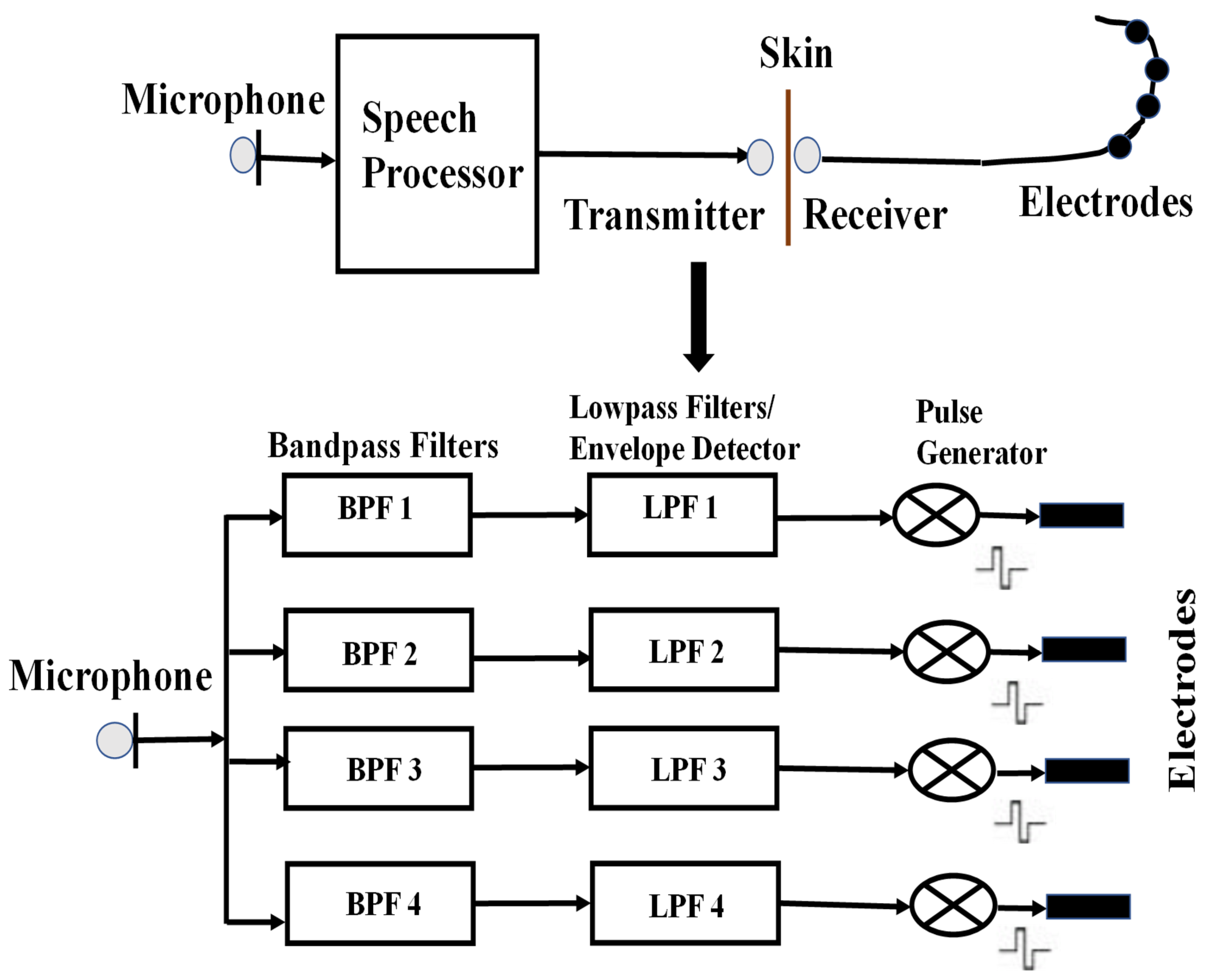
To investigate the application of GTFs in cochlear implantation, a commercially available cochlear implant processor model called Clarion [
33,
42], as shown in
Figure 9, is used in this work. The Clarion processor uses a microphone, worn at ear level, to capture the incoming sound. The sound is digitized and analyzed by a processor. The processor divides the signal into several channels based on frequency and translates the information in each channel into instructions that are transmitted to and control an implanted receiver that drives the implanted electrode array. The array of electrodes consists of 6–22 intra-cochlear electrodes distributed along the length of the cochlea. Stimuli delivered to an electrode preferentially excite the nerve fibers nearby.
The proposed model slightly varies from the Clarion processor. In the proposed model, the audio signal is first pre-emphasized [
48] to boost the higher frequency components, as shown in
Figure 10. The signal is then divided into channels by a set of GTFs instead of bandpass filters that are used in the Clarion processor. The main reason is that the bandpass filters do not represent the way the human auditory system responds to sounds. In addition, the hardware implementation of the bandpass filters is not as straightforward as the GTF. The next stage in the implant’s processing is the extraction of the envelope of the signal from each channel. This is achieved by rectification and lowpass filtering. Full-wave rectification is used in this model. A dc component is introduced during the rectification methods, and the harmonics that typically fall above the Nyquist frequency are aliased to lower frequencies. The rectified signal is lowpass filtered using a 16th-order moving-average filter [
49]. In a cochlear implant, the amplitude envelopes of each channel modulate a biphasic pulse train, which has a repetition rate of 800 to 4000 pulses per second (pps). Each modulated pulse train is delivered to a separate electrode, emulating the tonotopic arrangement of the cochlea. The GTFs are designed to cover a range of frequencies representing the basilar membrane [
50,
51,
52,
53,
54]. In this work, these filters were designed based on the specifications mentioned in [
21]. The center frequency and the bandwidth of these eight GTFs are listed in
Table 1, and the magnitude spectrum of the GTF bank is shown in
Figure 11. Those GTFs perform spectral analysis and convert an acoustic wave into a multichannel representation by mimicking the basilar membrane motion [
55]. These GTFs have been designed in a way that
as mentioned above. The filter order
was set to 4.0. The shape of the magnitude characteristic of the GTFs with order
is very similar to that of the
function [
56] that is commonly used to represent the magnitude response of the human auditory filter [
57].
5. Design Issues and Challenges
Despite the impressive ability of cochlear implants to improve sound audibility and speech understanding in profoundly deaf people, several significant challenges remain to address to maximize the benefits of this device. One major challenge is the substantial variability of audio perception among different gender groups, demographics, and ages. Research is still ongoing to correlate neural and cognitive function in cochlear implant users. There is a need to devise simple assessment measures to evaluate the perceptional outcomes of cochlear implant users. Poorer frequency discrimination abilities and neural deficits resulting from long-term deafness pose extra challenges to audio perception for cochlear implant users [
58,
59]. Rather than a physiologic point of view, some technological issues also need future investigation. A healthy cochlea transmits temporal-frequency information of audible sounds through around 3000 inner hair cells, but an implanted version could deliver a degraded version of such information resulting from signal processing (e.g., signal compression, bandpass filtering, temporal envelope extraction) and only a small number (up to eight) of electrodes in this design. As mentioned above, the number of spectral channels used for most CI users is likely less than eight due to factors including channel interactions. Signal processing also removes delicate temporal structures that may hinder normal hearing regarding melody contents [
60].
While cochlear implants have proven to be beneficial for many individuals with profound hearing loss, there are some potential drawbacks to consider:
Cost: The potential physiological design challenges mentioned above could make cochlear implants expensive, and the cost may not always be fully covered by insurance. This financial aspect can be a barrier for some individuals.
Surgical Risks: Though the implantation process involves a mild surgery, like any surgical procedure, there are inherent risks like infections, bleeding, and issues related to anesthesia.
Learning Curve: Adjusting to hearing with a cochlear implant requires time and effort. Some individuals may find the initial period challenging as they learn to interpret the new auditory signals.
Maintenance and Upkeep: Cochlear implants require ongoing maintenance, including regular checks and adjustments. The external components also need to be cared for to ensure optimal functioning.
It is essential for individuals considering cochlear implants to discuss these aspects with their healthcare providers and audiologists. Despite these considerations, many people with cochlear implants experience significant improvements in their ability to hear and communicate.

