
Design of an Optically Accessible Intake Manifold for Characterization of Liquid and Gaseous Jets in PFI Operating Conditions


Abstract
:1. Introduction
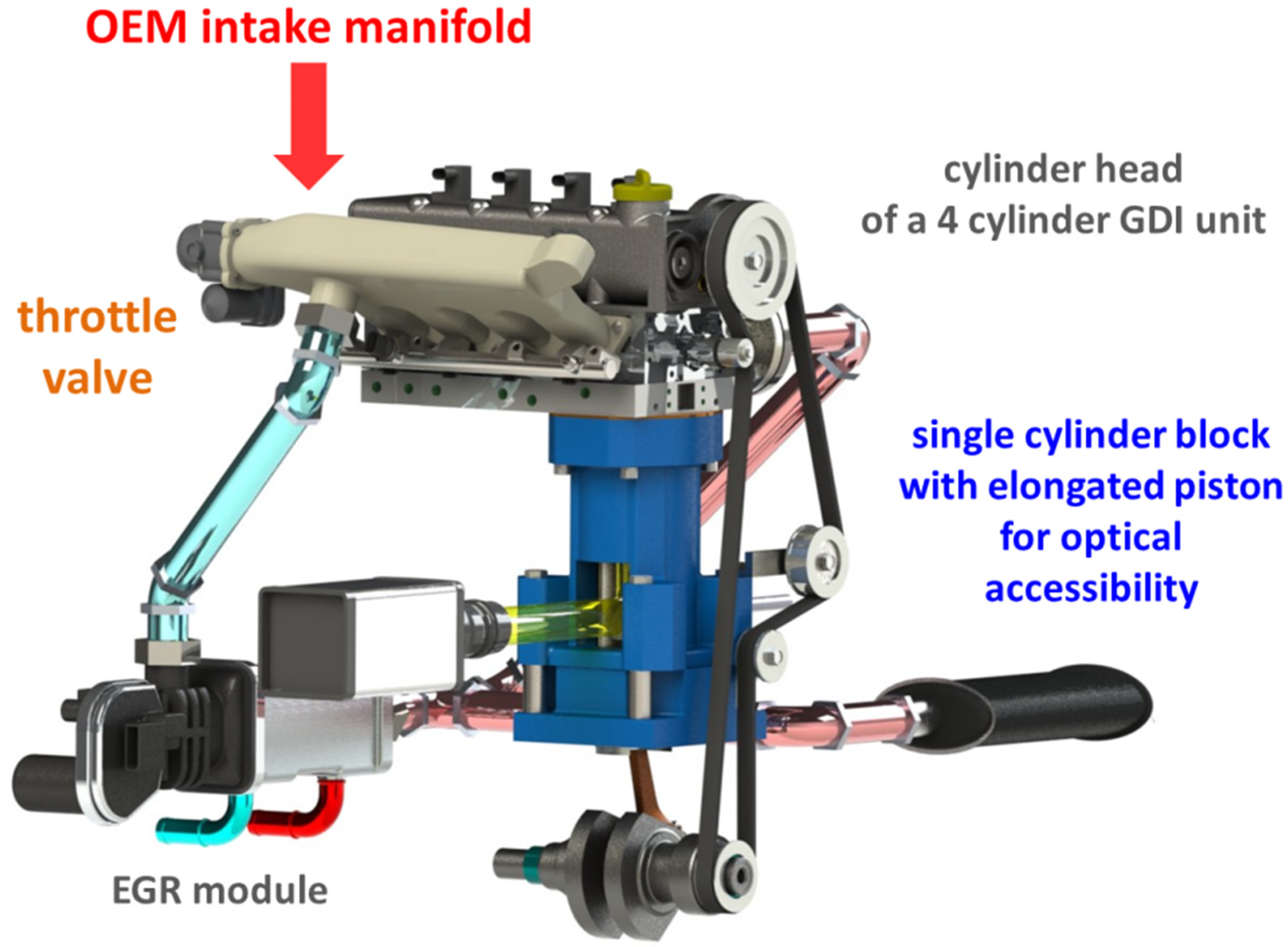
2. Engine Setup
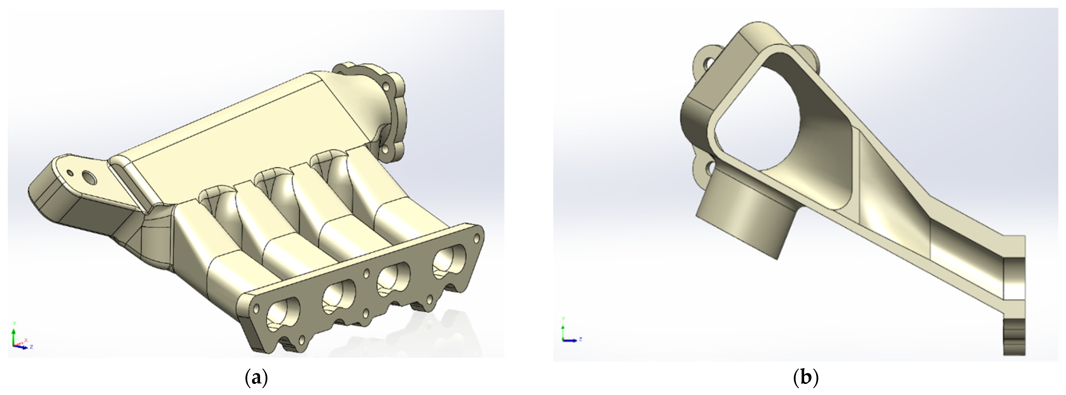
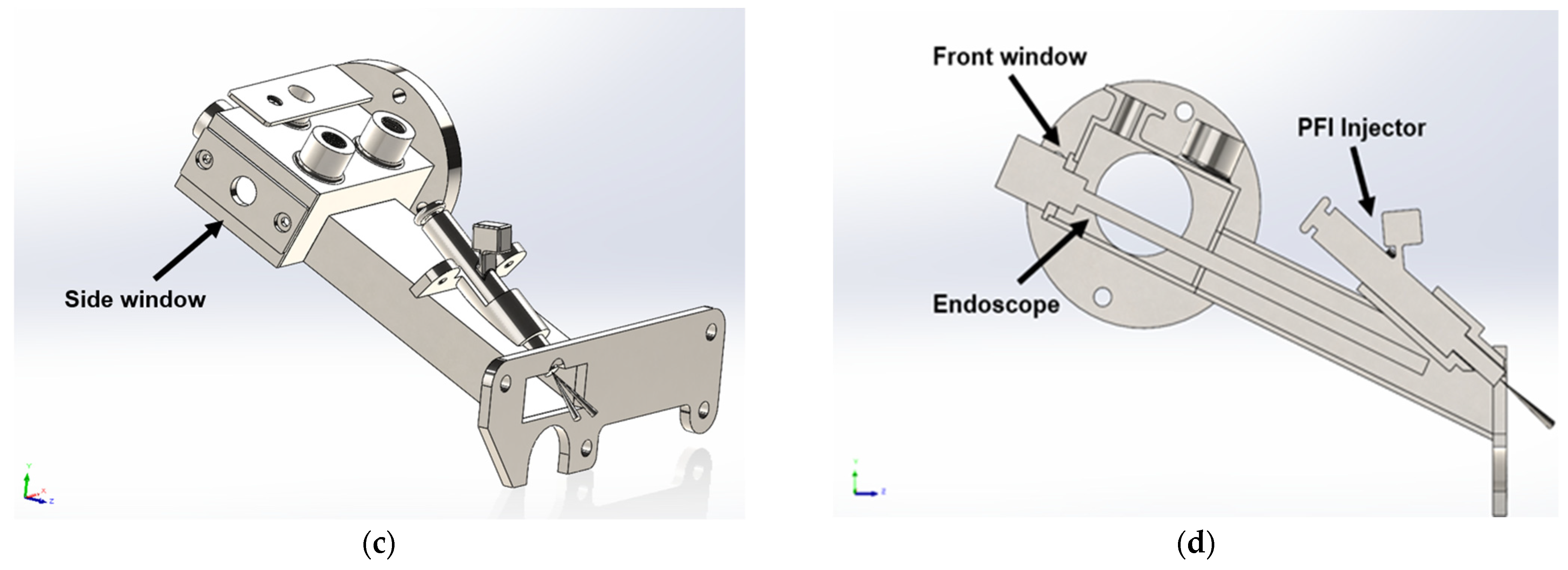
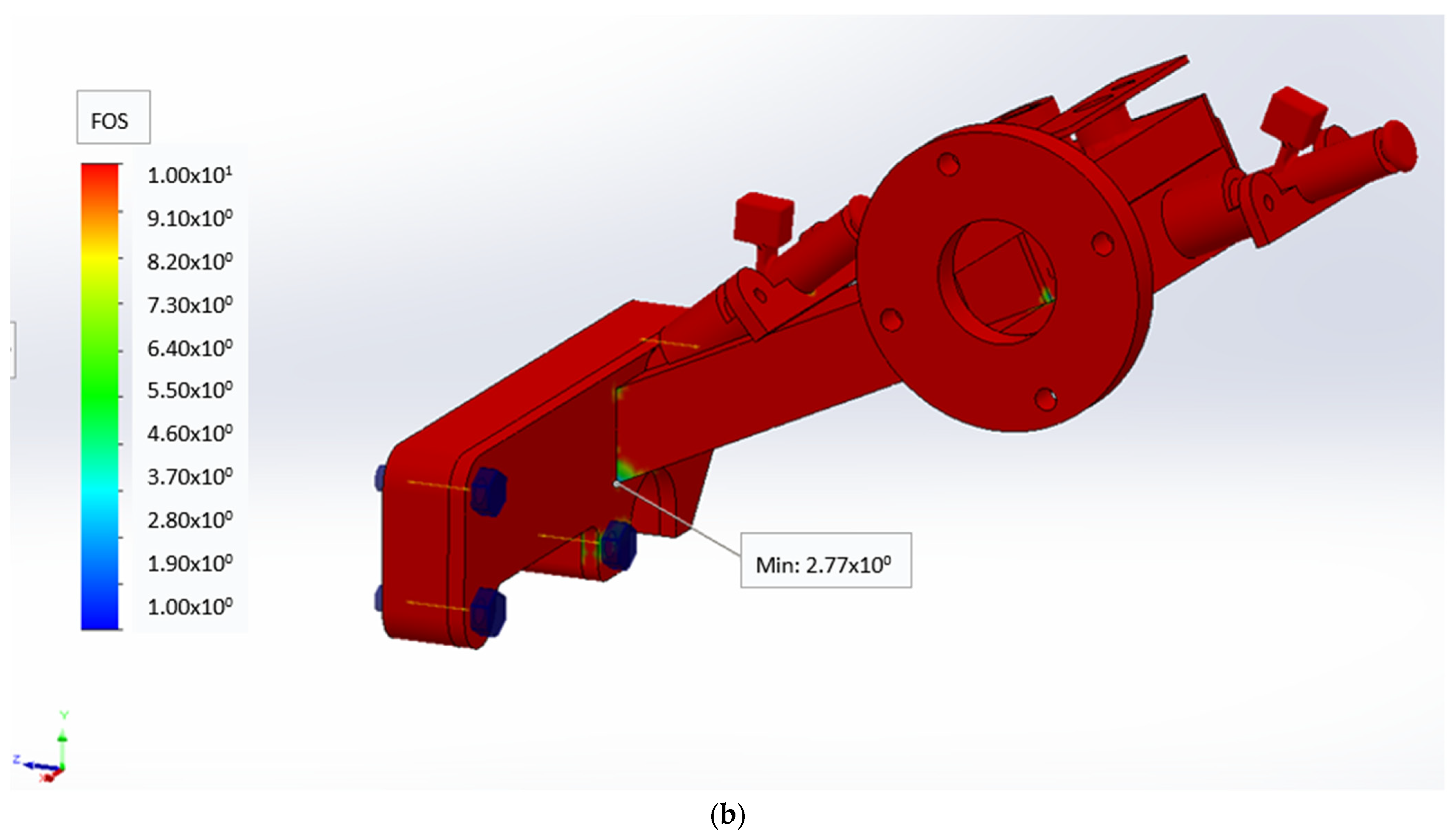
3. 3D Model
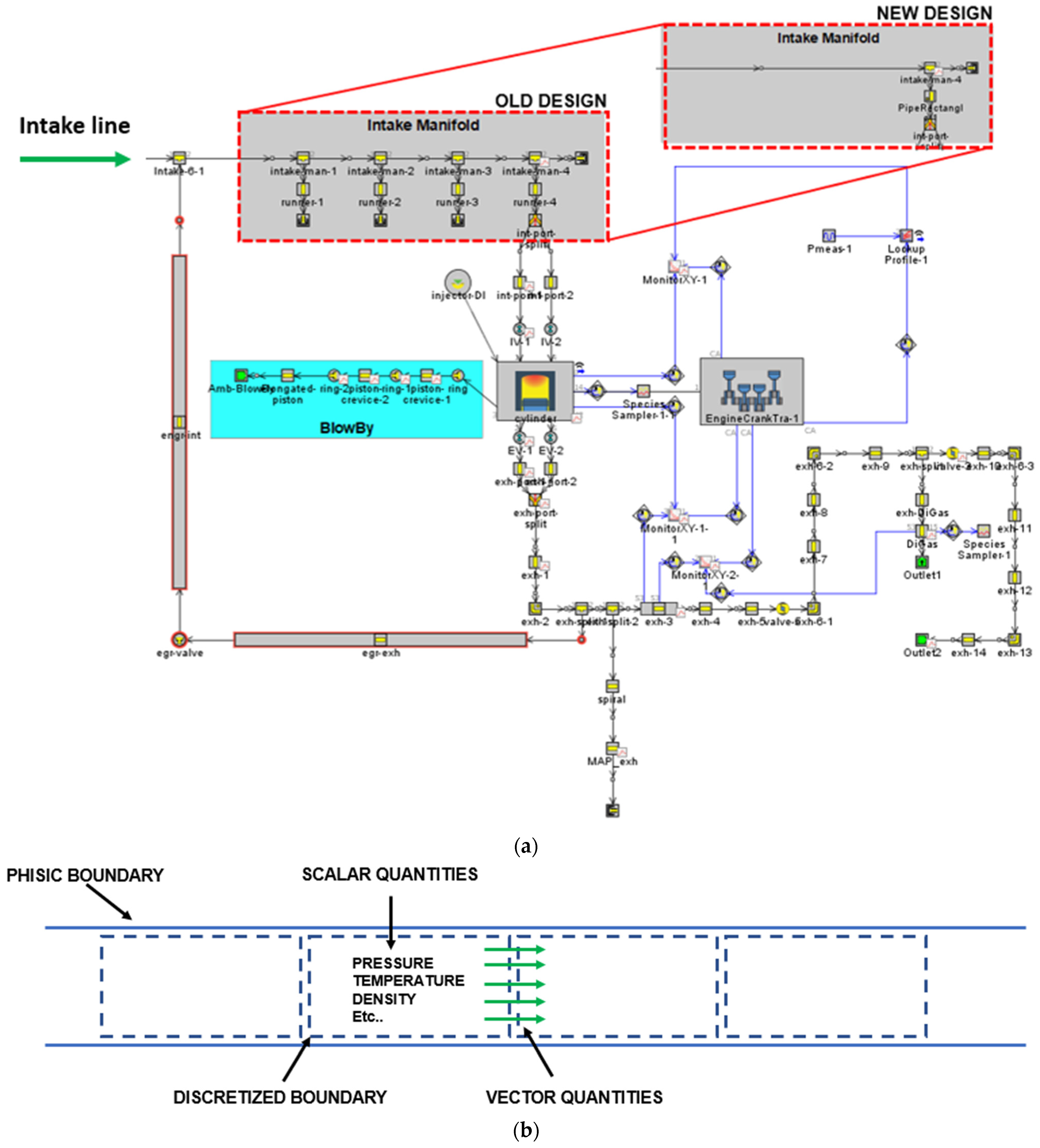
4. Numerical Model
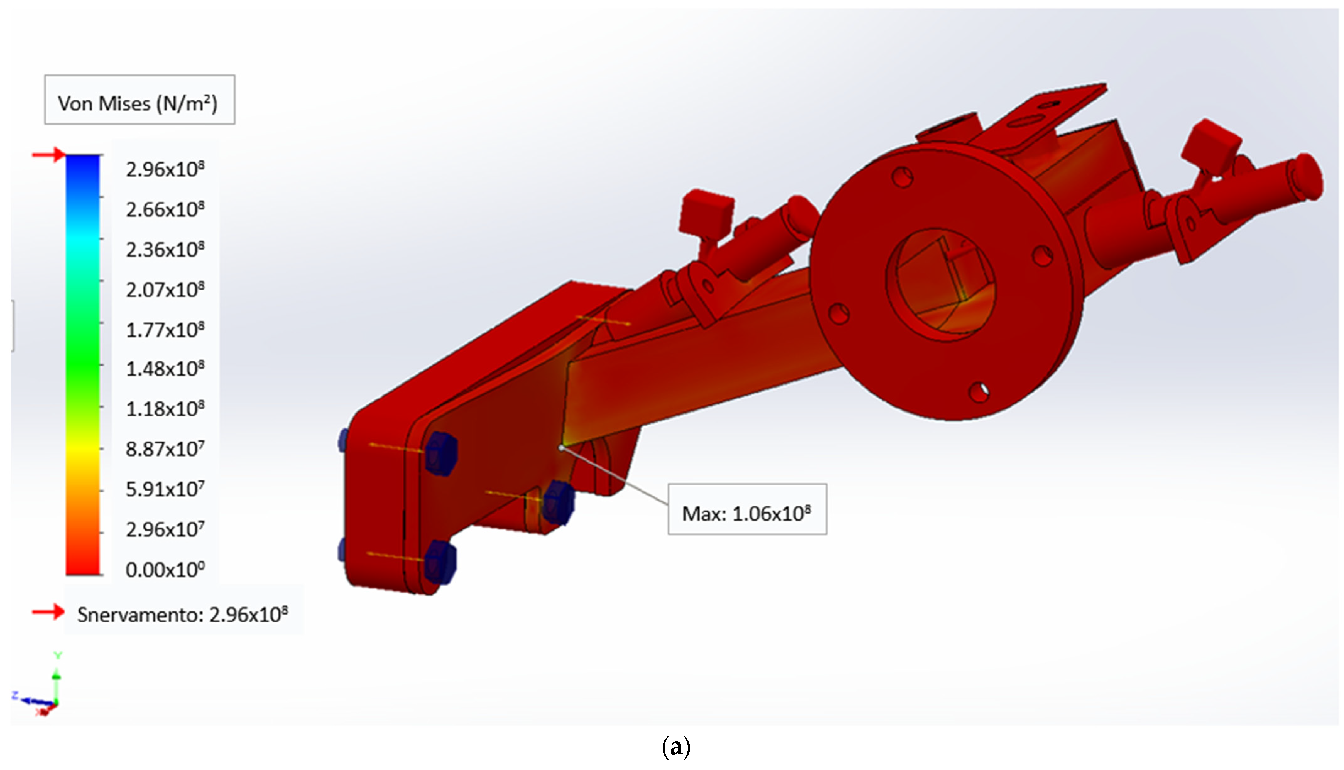
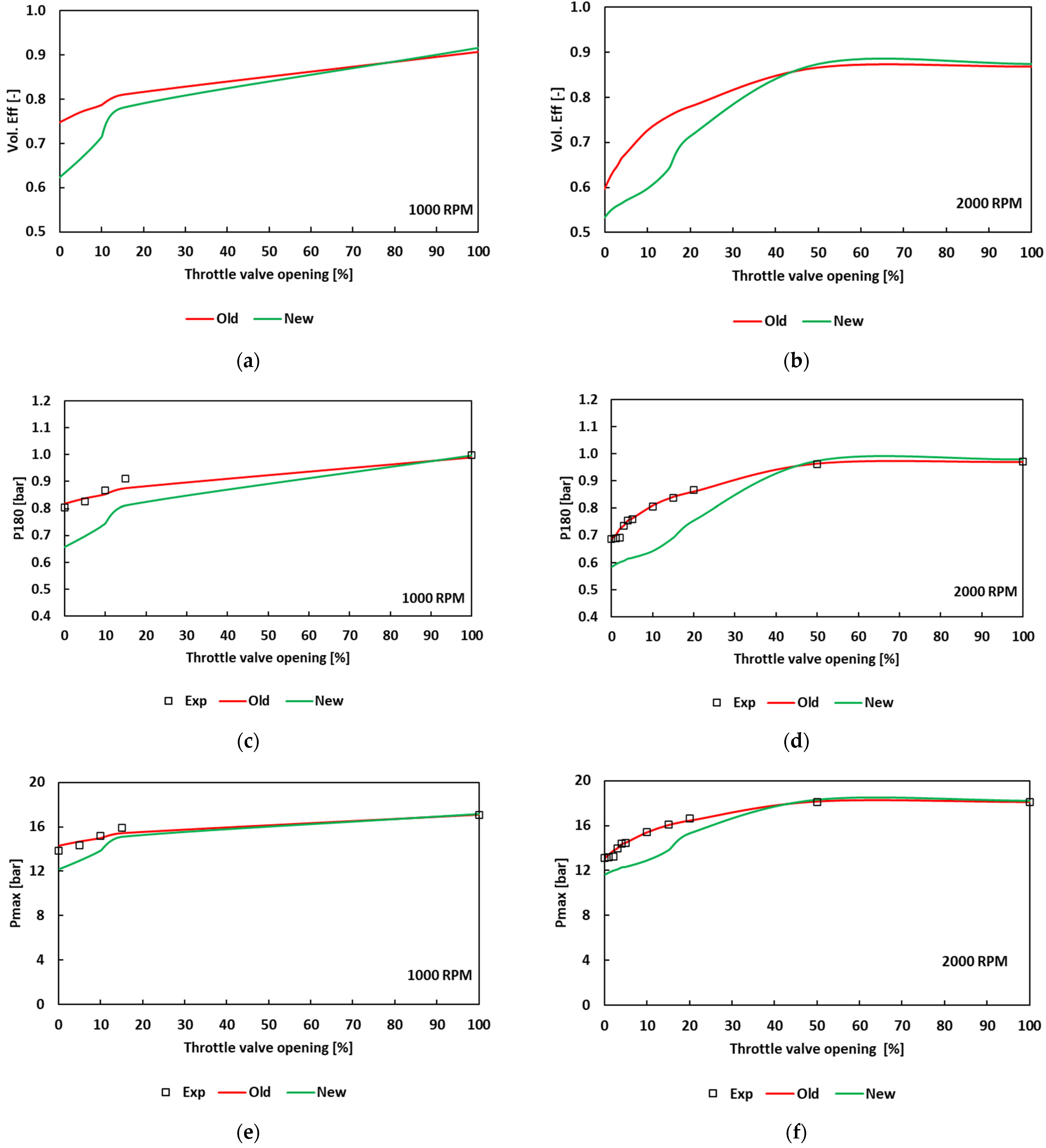
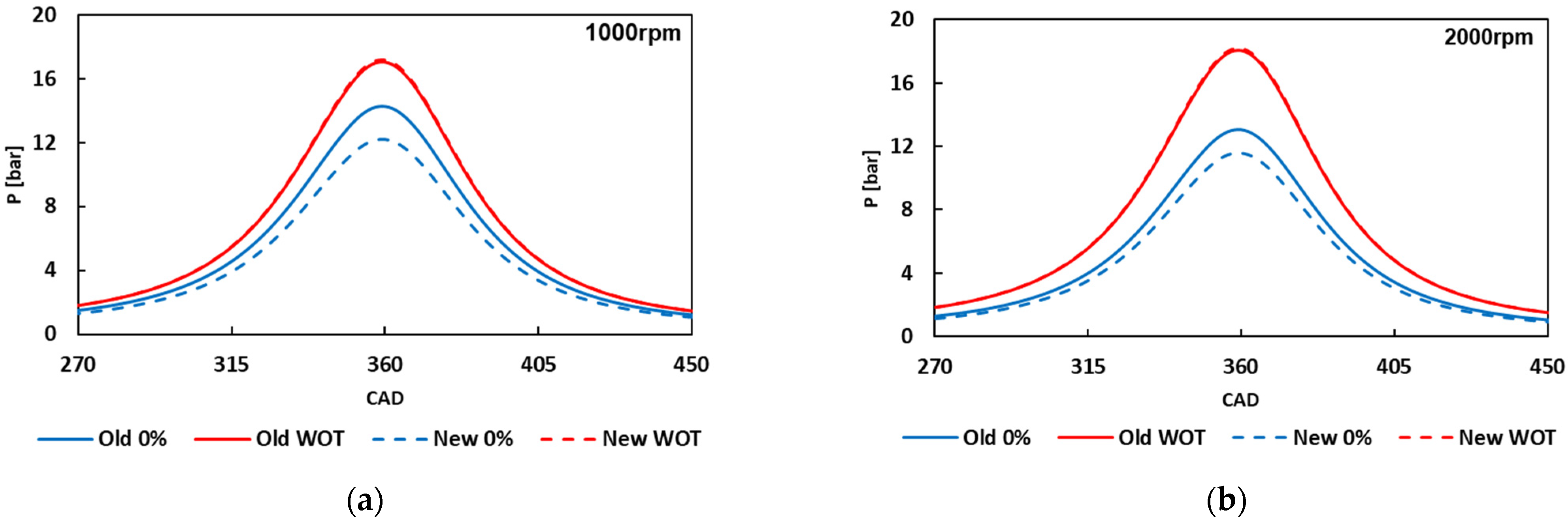
5. Results
6. Conclusions
Author Contributions
Funding
Data Availability Statement
Acknowledgments
Conflicts of Interest
References
- Samaras, Z.; Kontses, A.; Dimaratos, A.; Kontses, D.; Balazs, A.; Hausberger, S.; Ntziachristos, L.; Andersson, J.; Ligterink, N.; Aakko-Saksa, P.; et al. A European Regulatory Perspective towards a Euro 7 Proposal; SAE Technical Paper: 2022-37-0032; SAE International: Warrendale, PA, USA, 2022. [Google Scholar] [CrossRef]
- Heywood, J.B.; Welling, O. Trends in Performance Characteristics of Modern Automobile SI and Diesel Engines. SAE Int. J. Engines 2009, 2, 1650–166262. [Google Scholar] [CrossRef]
- Rakopoulos, C.D.; Hountalas, D.; Zannis, T.; Levendis, Y. Operational and Environmental Evaluation of Diesel Engines Burning Oxygen-Enriched Intake Air or Oxygen-Enriched Fuels: A Review; SAE Technical Paper: 2004-01-2924; SAE International: Warrendale, PA, USA, 2004. [Google Scholar] [CrossRef]
- Zannis, T.C.; Hountalas, D.T. DI diesel engine performance and emissions from the oxygen enrichment of fuels with various aromatic content. Energy Fuels 2004, 18, 659–666. [Google Scholar] [CrossRef]
- Abidi, S.H.; Hasan, M.M. Review on Studying Effects of Enhancing Turbulence by Modifying the Intake Manifold of Internal Combustion Engine. In Recent Advances in Mechanical Engineering, Lecture Notes in Mechanical Engineering; Muzammil, M., Chandra, A., Kankar, P.K., Kumar, H., Eds.; Springer: Singapore, 2021; pp. 361–368. [Google Scholar] [CrossRef]
- Singla, S.; Sharma, S.; Gangacharyulu, D. Study of design improvement of intake manifold of internal combustion engine. Int. J. Eng. Technol. Manag. Appl. Sci. 2015, 3, 234–242. [Google Scholar]
- Heywood, J.B. Internal Combustion Engine Fundamentals; McGraw Hill: New York, NY, USA, 1988. [Google Scholar]
- Delogu, M.; del Pero, F.; Romoli, F.; Pierini, M. Life cycle assessment of a plastic air intake manifold. Int. J. Life Cycle Assess. 2015, 20, 1429–1443. [Google Scholar] [CrossRef]
- Silva, E.A.A.; Ochoa, A.A.V.; Henríquez, J.R. Analysis and runners length optimization of the intake manifold of a 4-cylinder spark ignition engine. Energy Convers. Manag. 2019, 188, 310–320. [Google Scholar] [CrossRef]
- Ceviz, M.A.; Akın, M. Design of a new SI engine intake manifold with variable length plenum. Energy Convers. Manag. 2010, 51, 2239–2244. [Google Scholar] [CrossRef]
- Alves, L.O.F.T.; dos Santos, M.G.D.; Urquiza, A.B.; Guerrero, J.H.; de Lira, J.C.; Abramchuk, V. Design of a New Intake Manifold of a Single Cylinder Engine with Three Stages; SAE Technical Paper: 2017-36-0172; SAE International: Warrendale, PA, USA, 2017. [Google Scholar] [CrossRef]
- Taylor, J.; Gurney, D.; Freeland, P.; Dingelstadt, R.; Stehlig, J.; Bruggesser, V. Intake Manifold Length Effects on Turbocharged Gasoline Downsizing Engine Performance and Fuel Economy; SAE Technical Paper: 2012-01-0714; SAE International: Warrendale, PA, USA, 2012. [Google Scholar] [CrossRef]
- Shinde, P.A. Research and optimization of intake restrictor for Formula SAE car engine. Int. J. Sci. Res. Publ. 2014, 4, 1–5. [Google Scholar]
- Castellano, A.; Leone, D.; Cammalleri, M. Design of a Hybrid Electric Power-Split Transmission for Braking Energy Recovery in a Drilling Rig. Designs 2022, 6, 74. [Google Scholar] [CrossRef]
- Diéguez, P.M.; Urroz, J.C.; Sáinz, D.; Machin, J.; Arana, M.; Gandía, L.M. Characterization of combustion anomalies in a hydrogen-fueled 1.4 L commercial spark-ignition engine by means of in-cylinder pressure, block-engine vibration, and acoustic measurements. Energy Convers. Manag. 2018, 172, 67–80. [Google Scholar] [CrossRef]
- Abdellatif, Y.M.; Saker, A.T.; Elbashir, A.M.; Ahmed, S.F. Combustion and Emissions of a Gas-to-Liquid Diesel Engine Utilizing Optimized Spiral-Helical Intake Manifold Designs. ASME. J. Energy Resour. Technol. 2021, 143, 062308. [Google Scholar] [CrossRef]
- Ceviz, M.A. Intake plenum volume and its influence on the engine performance, cyclic variability and emissions. Energy Convers. Manag. 2007, 48, 961–966. [Google Scholar] [CrossRef]
- Elbashir, A.M.; Saker, A.T.; Ahmed, S.F. Effect of Utilizing a Novel Intake Manifold Design on Smoke Emissions and Particulate Size Distributions of a Gas-to-Liquid Diesel Engine. ASME. J. Energy Resour. Technol. 2022, 144, 022301. [Google Scholar] [CrossRef]
- Sadeq, A.M.; Bassiony, M.A.; Elbashir, A.M.; Ahmed, S.F.; Khraisheh, M. Combustion and emissions of a diesel engine utilizing novel intake manifold designs and running on alternative fuels. Fuel 2019, 255, 115769. [Google Scholar] [CrossRef]
- Kadarohman, A.; Khoerunnisa, F.; Sapee, S.; Eko Sardjono, R.; Izzudin, I.; Hendrawan; Mamat, R.; Yusop, A.F.; Erdiwansyah; Yusaf, T. The Effect of Oxygenated Turpentine Oil Additive in Diesel Fuel on the Performance and Emission Characteristics in One-Cylinder DI Engines. Designs 2021, 5, 73. [Google Scholar] [CrossRef]
- Sick, V. Optical diagnostics for direct injection gasoline engine research and development. In Advanced Direct Injection Combustion Engine Technologies and Development; Hua Zhao, Ed.; Woodhead Publishing Limited: Sawston, UK, 2009; Chapter 10; pp. 260–286. ISBN 978-1-84569-389-3. [Google Scholar]
- Ikeda, Y. The Interaction between In-Cylinder Turbulent Flow and Flame Front Propagation in an Optical SI Engine Measured by High-Speed PIV. Energies 2022, 15, 2783. [Google Scholar] [CrossRef]
- Laichter, J.; Kaiser, S.A. Optical Investigation of the Influence of In-cylinder Flow and Mixture Inhomogeneity on Cyclic Variability in a Direct-Injection Spark Ignition Engine. Flow Turbul. Combust. 2023, 110, 171–183. [Google Scholar] [CrossRef]
- Irimescu, A.; Merola, S.S.; Vaglieco, B.M. Towards better correlation between optical and commercial sparks ignition engines through quasi-dimensional modeling of cycle-to-cycle variability. Therm. Sci. 2022, 26, 1685–1694. [Google Scholar] [CrossRef]
- Merola, S.S.; Irimescu, A.; Marchitto, L.; Tornatore, C.; Valentino, G. Effect of injection timing on combustion and soot formation in a direct injection spark ignition engine fueled with butanol. Int. J. Engine Res. 2017, 18, 490–504. [Google Scholar] [CrossRef]
- Johnen, T.; Haug, M. Spray Formation Observation and Fuel Film Development Measurements in the Intake of a Spark Ignition Engine; SAE Technical Paper: 950511; SAE International: Warrendale, PA, USA, 1995. [Google Scholar] [CrossRef]
- Bruno, B.; Santavicca, D.; Zello, J. LIF Characterization of Intake Valve Fuel Films During Cold Start in a PFI Engine; SAE Technical Paper: 2002-01-2751; SAE International: Warrendale, PA, USA, 2002. [Google Scholar] [CrossRef]
- Dhyani, V.; Subramanian, K.A. Fundamental characterization of backfire in a hydrogen fuelled spark ignition engine using CFD and experiments. Int. J. Hydrog. Energ. 2019, 44, 32254–32270. [Google Scholar] [CrossRef]
- Jüngst, N.; Frapolli, N.; Wright, Y.M.; Boulouchos, K.; Kaiser, S.A. Experimental and numerical investigation of evaporating fuel films in combustion. Appl. Energ. Combust. Sci. 2021, 7, 100033. [Google Scholar] [CrossRef]
- Gao, J.; Wang, X.; Song, P.; Tian, G.; Ma, C. Review of the backfire occurrences and control strategies for port hydrogen injection internal combustion engines. Fuel 2022, 307, 121553. [Google Scholar] [CrossRef]
- Bowditch, F. A New Tool for Combustion Research A Quartz Piston Engine; SAE Technical Paper: 610002; SAE International: Warrendale, PA, USA, 1961. [Google Scholar] [CrossRef]
- Irimescu, A. Back-Pressure and Fuel Type Effects on Exhaust Gas Oxygen Sensor Readings for a Single Cylinder Spark Ignition Engine Running on Gasoline and Ethanol; SAE Technical Paper: 2019-24-0046; SAE International: Warrendale, PA, USA, 2019. [Google Scholar] [CrossRef]
- Gamma Technologies. GT-SUITE Flow Theory Manual Version 2019; Gamma Technologies: Westmont, IL, USA, 2019. [Google Scholar]
- BOSCH Catalogue, Equipment for High Performance Vehicles, Electronic Throttle Body. Edition 2020. Available online: www.bosch-motorsport.com (accessed on 15 December 2022).


| Engine Specification | |
|---|---|
| Number of cylinders | 1 |
| Compression ratio | 10:1 |
| Bore | 79 mm |
| Stroke | 81.3 mm |
| Number of valves | 4 |
| Injection setup | direct injection wall guided |
| Exhaust Valves Open | 153 CAD aTDC |
| Exhaust Valves Close | 360 CAD aTDC |
| Intake Valves Open | 363 CAD bTDC |
| Intake Valves Close | 144 CAD bTDC |
| Engine Condition | Speed [rpm] | Throttle Valve Opening [%] |
|---|---|---|
| Motored | 1000 | 0-5-10-15-100 |
| 2000 | 0-1-2-3-4-5-10-15-20-50-100 |
Disclaimer/Publisher’s Note: The statements, opinions and data contained in all publications are solely those of the individual author(s) and contributor(s) and not of MDPI and/or the editor(s). MDPI and/or the editor(s) disclaim responsibility for any injury to people or property resulting from any ideas, methods, instructions or products referred to in the content. |
© 2023 by the authors. Licensee MDPI, Basel, Switzerland. This article is an open access article distributed under the terms and conditions of the Creative Commons Attribution (CC BY) license (https://creativecommons.org/licenses/by/4.0/).
Share and Cite
Cecere, G.; Irimescu, A.; Merola, S.S. Design of an Optically Accessible Intake Manifold for Characterization of Liquid and Gaseous Jets in PFI Operating Conditions. Designs 2023, 7, 24. https://doi.org/10.3390/designs7010024
Cecere G, Irimescu A, Merola SS. Design of an Optically Accessible Intake Manifold for Characterization of Liquid and Gaseous Jets in PFI Operating Conditions. Designs. 2023; 7(1):24. https://doi.org/10.3390/designs7010024
Chicago/Turabian StyleCecere, Giovanni, Adrian Irimescu, and Simona Silvia Merola. 2023. "Design of an Optically Accessible Intake Manifold for Characterization of Liquid and Gaseous Jets in PFI Operating Conditions" Designs 7, no. 1: 24. https://doi.org/10.3390/designs7010024
APA StyleCecere, G., Irimescu, A., & Merola, S. S. (2023). Design of an Optically Accessible Intake Manifold for Characterization of Liquid and Gaseous Jets in PFI Operating Conditions. Designs, 7(1), 24. https://doi.org/10.3390/designs7010024