Article

Study of Energy Loss for Distributed Power-Flow Assignment in a Smart Home Environment

1
School of Information Science, Japan Advanced Institute of Science and Technology, 1-1 Asahidai, Nomi 923-1292, Japan
2
School of Information, Computer, and Communication Technology (ICT), Sirindhorn International Institute of Technology, Thammasat University, Pathum Thani 12120, Thailand
*
Author to whom correspondence should be addressed.
Designs 2022, 6(6), 99; https://doi.org/10.3390/designs6060099
Submission received: 21 September 2022 / Revised: 18 October 2022 / Accepted: 19 October 2022 / Published: 24 October 2022
(This article belongs to the Special Issue Smart Home Design)

Abstract

:
Today, renewable energy resources are a critical component of distributed energy systems. However, their intermittent nature makes them unstable energy sources, making them very difficult to use optimally in any energy system. Battery storage is a viable solution for this issue. In this paper, we consider distributed power-flow assignment consisting of unstable power generators, unpredictable power loads, and multiple energy storage systems (ESSs), with different combinations of logical power connections between them. We propose power-flow assignment (PFA) algorithms to deal with single and multiple loads to address the possibility of reducing energy loss and improving distributed power-flow assignment with the presence of ESSs in a smart home environment. Simulation results reveal that the increment of logical power connections between generators, loads, and storage systems can significantly reduce energy loss. The proposed PFA algorithms can reduce energy loss by about 67% compared to a power-flow assignment for which all the generated power is stored in an ESS directly during winter. The results further show that spring has the highest energy loss and stored energy in ESS compared to other seasons.

1. Introduction

World energy demand is continuously increasing [1]. Since it is not environmentally friendly, constructing more fossil fuel power plants is not an excellent answer to deal with such a problem. On the other hand, renewable energy resources such as solar panels, wind turbines, and fuel cells do not produce harmful C O 2 emissions [2]. The development of advanced technologies and the decrease in renewable energy (RE) costs make RE very interesting for many involved parties. However, the intermittent nature of RE makes it an unstable energy resource that cannot be utilized fully. Thus, energy storage systems (ESSs) are a viable solution for mitigating this issue. Especially in the residential sector, people are becoming more interested in producing their energy by using RE integrated with an ESS. These days, not only has the cost of RE decreased, but the installation cost of ESSs has also decreased by 60% from 2014 to 2017. Moreover, it is predicted to further decrease up to 61% by 2030 compared to 2017 [3].
Smart homes are a promising trend for utilizing energy in the residential sector. The American Association of House Builders used the term ’smart home’ in 1984, as F.K. Aldrich remarked [4]. Over the past decades, the smart home concept has evolved rapidly with the growth of the Internet, becoming a house in which home appliances and devices are fully interconnected. Nowadays, it is typically considered to be a single house with RE resources such as solar photovoltaics (PVs), fuel cells (FCs), and so on [5] integrated with various home appliances. The current trend of energy usage of home appliances has changed from the traditional way due to the introduction of the Internet of Things (IoT), Power Line Communication (PLC), and Power over Ethernet (PoE) technologies. IoT is utilized in a smart home. It allows the home’s controller to communicate with various home appliances to collect and monitor load profile data and take optimal control by turning on/off operations. While communication technologies such as Wi-Fi, Bluetooth Low Energy (BLE), LoRaWAN, WiSUN, ZigBee, and so on can be used for IoT purposes, Ethernet is a good option to control home appliances promptly and directly. PoE delivers electric energy and information to home appliances via an Ethernet cable. PoE has evolved into a new technology called Single-pair Ethernet (SPE). SPE consists of only two twisted wires that can deliver both electric energy and information. It is a very viable option and a promising trend for future smart homes due to its low cost and small-deployment size compared to traditional PoE technology [6].
In order to fully utilize RE together with ESS, an efficient system design for integrating REs with ESSs is highly needed. When designing any energy system, energy loss should be minimized to ensure energy efficiency [7]. Today, the design of energy systems in a distributed way that incorporates RE resources and human activities is essential. As people’s activities in a house are becoming more complicated, it is necessary to ensure a balanced, reliable, and safe energy supply to all home appliances from RE resources. The problems of intermittency and power fluctuations in renewable energy resources makes an ESS indispensable. Therefore, it is essential not only to balance power supply and demand in home energy management [8] but also to ensure reliable and safe energy flow in distributed power-flow systems [9], which must have an ESS to provide continuous energy capacity to meet real-time power demands. In our previous work [10], we studied the optimal ESS size to ensure reliable and safe energy flow in distributed power-flow assignment (DPFA) while balancing renewable power supplies and fluctuating power demands utilizing a real experimental dataset based on daily human activities in a smart home for the fundamental design of DPFA for four different seasons. In fluctuating DPFA, the number of logical power connections of the energy system affects the energy loss of an ESS. Therefore, in this paper, our objective is to study the energy loss of ESSs for single and multiple power load fluctuating DPFAs in a smart home.
The main contributions of this paper are as follows:
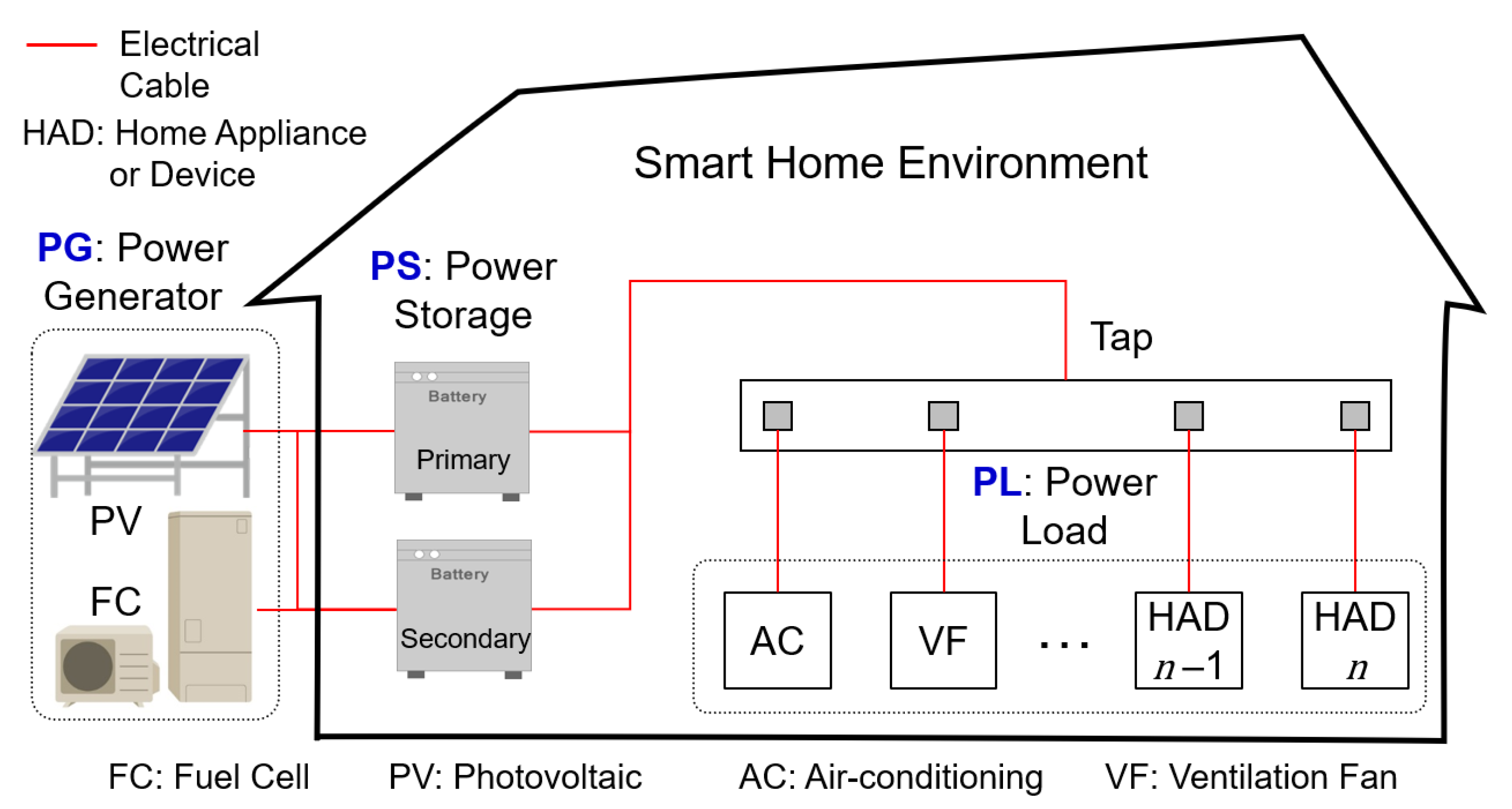
  • Introduce a system model of fluctuating DPFA to study balancing RE resources and power loads with the presence of ESSs in a smart home.
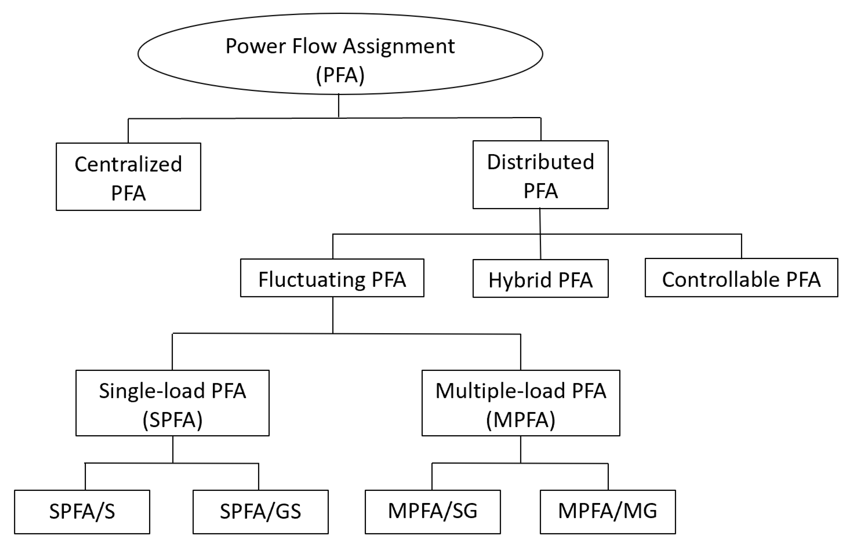
  • Propose power-flow assignment algorithms for the energy system to efficiently assign the required power for single and multiple power loads, i.e., single-load power-flow assignment (SPFA) and multiple-load power-flow assignment (MPFA) algorithms, respectively.
  • Reveal through simulation results that the proposed PFA algorithms ensure that the total energy from PGs from RE resources are completely supplied to all the PLs in order to reduce energy loss due to ESSs.
This paper is arranged as follows. Section 2 and Section 3 provide the background of distributed power-flow assignment and the literature review of this paper, respectively. Section 4 presents the system model of the distributed power-flow system for a smart home with RE and ESS, together with the model for each power device and energy-loss calculation. In Section 5, the power-flow assignment algorithms in the distributed power-flow system are explained. The simulation results of this work are described and discussed in Section 6. Finally, the conclusions and future work are discussed in Section 7.

2. Background

Figure 1 shows the classification of power-flow assignment (PFA) in a smart home, which implies logical power-flow connections for an energy system over SPE technology to deliver electric energy and information to all the home appliances via Ethernet cables. First, PFA can be divided mainly into centralized and distributed in the presence of ESSs. In a centralized PFA (CPFA), the power supply logically supplies its power to the required power loads through the on/off switch of a power tap, which is controlled by a controller. On the other hand, a distributed PFA (DPFA) consists of various types of power generators that logically supply their power to the required power loads and are also controlled by a controller. In DPFA, a single power load can obtain power from more than one power generator. Similarly, a single power generator can supply power to more than one power load. Further, DPFA can be classified into three types: controllable DPFA, fluctuating DPFA, and hybrid DPFA, which combines controllable DPFA and fluctuating DPFA in the energy system.
In this paper, we focus our work on fluctuating DPFA energy systems because it is a challenging problem to look into how a single house can operate independently from fluctuating RE resources (e.g., photovoltaic cells, fuel cells, wind turbines, and so on) to all the fluctuating home appliances without a utility power supply. In fluctuating DPFA, we study PFA algorithms to determine how fluctuating RE resources can logically supply their power to fluctuating power loads. For the sake of simplicity, we first look into a single power generator for a single power load, and we call it a ’single-load PFA’ (SPFA). In SPFA, a single power load can obtain its power from an ESS only or from a single power generator directly plus an ESS. Hereinafter, we call the logical power connection from a single power generator to a single power load via an ESS an ’SPFA/S’. Meanwhile, we call the logical power connection from a single power generator to a single power load via a single power generator directly and through an ESS an ’SPFA/GS’. Second, we look into multiple power generators to multiple power loads, and we call this ’multiple-load PFA’ (MPFA). In MPFA, the power load can obtain its power from both the power generators directly and from a single or multiple ESSs. However, ESS charging depends on the remaining power from either a single or multiple power generators. In particular, if the power load can obtain its power from both the power generator directly and from an ESS, and the ESS is charged using the power remaining from a single power generator, we call it an ’MPFA/SG’. Futher, if the power load can obtain its power from both multiple power generators directly and from multiple ESSs, and the ESSs are charged from the power remaining from multiple power generators, we call it an ’MPFA/MG’.

3. Related Works

In smart homes, a Home Energy Management System (HEMS) is one of the promising trends for efficient energy management. Many studies have focused on this research path. Optimal scheduling of home appliances to reduce the electricity bill is studied in [11,12,13,14]. In [11], M. Javadi et al. introduce the self-scheduling of HEMS by forming a multi-objective optimization problem in which the first objective is to minimize the daily bill of the household, and the second objective is to minimize discomfort. T. Almeida et al. [12] propose optimal management that coordinates both HEMS and an EV parking lot management system (EVPLMS). The optimal self-scheduling of home appliances in the presence of an inverter-based AC system for smart homes is presented in [13]. A. Jordehi et al. [14] propose a novel particle-swarm optimizer for determining optimal home appliance scheduling in HEMS. The problem is solved for two smart homes with 10 and 11 appliances, including an electric vehicle.
We further review work related to ESSs in three aspects: integration of RE resources, charging and discharging efficiency, and power assignment. There are many works on energy loss when integrating RE resources with ESSs. In particular, optimal ESS sizing, ESS placement, and control of ESS considering energy losses are studied in [15,16,17,18]. In [15], P. Fortenbacher et al. use multi-period optimal power flow to schedule optimal battery storage operations. Their findings show that the proposed method can reduce battery losses by 30%. Additionally, a novel algorithm for optimal control and placement of ESSs for minimizing energy losses using a genetic algorithm is proposed in [16]. M. Jannesar et al. [17] propose an optimal method for sizing, placing, and daily charging/discharging of ESSs based on a cost function that considers energy losses. The results show a decrease in energy losses. J. Sardi et al. [18] manage to obtain the optimal ESS capacity and analyze the energy loss reduction of an RE system integrated with an ESS through load leveling.
On the other hand, research in [19,20,21] specifically focuses on energy loss from charging and discharging of ESSs. In [19], Z. Chen et al. propose an optimal charging strategy for ESSs to minimize charging loss using a dynamic programming algorithm that reveals efficient results. A new charging algorithm for energy loss minimization is proposed in [20]. The results show that the proposed charging method can obviously reduce energy charging loss. K. Liu et al. [21] propose a novel multi-objective optimization framework to obtain optimal battery charging management considering charging cost from energy loss.
In recent years, a few research works [22,23,24] have focused on optimal power assignment in the presence of ESSs to improve the entire energy system’s efficiency. In [22], M. Schimpe et al. propose a power-flow distribution strategy to improve the energy efficiency of a system integrated with a second-life battery storage system. The goal is to reduce the energy loss of ESSs when possible by minimizing the operation time. The experimental test shows that energy loss can be reduced by 24%. Optimal power assignment to improve efficiency through an ESS operational algorithm is proposed in [23]. The ESS is used for frequency regulation, for which this work created a lookup table with a genetic algorithm for efficient ESS operation. The results confirm that the proposed strategy is highly effective for improving system efficiency. J. Choi et al. [24] propose a novel hierarchical control structure for a multiple-battery energy storage power-sharing system with an algorithm that selects the appropriate control.

4. System Model

4.1. Preliminaries

Figure 2 shows the system model of simple fluctuating distributed power-flow assignment (DPFA), which consists of two power generators (PGs), two power loads (PLs), and two power storage devices (PSs). A power generator can supply power to PL and PS. In our fundamental research analysis, we purposely select solar photovoltaic (PV) and a fuel cell (FC) as two PGs. A power load can receive power supplied by PGs and PSs, for which we use air conditioning (AC) and a ventilation fan (VF) as two PLs to study the effect of ESS energy loss and power fluctuations of both PGs and PLs on the PFS by keeping the state of charge (SoC) limitations of PSs. In this paper, the term “fluctuating” refers to uncontrollable PGs and PLs. In this paper, ’PS system’ also means the ESS in general. A power storage device can be charged by the power supplied from PGs and can discharge power to PLs. We use a tripartite graph model, as shown in Figure 3, to logically represent a power-flow connection between a PG, PL, and PS. A connection between two devices is denoted as a pair of two power devices, e.g., ( P G i , P L j ) represents the connection between the ith power generator, P G i , and the jth power load, P L j .
Suppose M , N , and H are a set of PGs, PLs, and PSs, respectively. Let E G m f ( t ) be a set of time-varying energy generation levels at time t that are served by the set of fluctuating PGs m M = { 1 , 2 , , M } . Similarly, E L n f ( t ) are a set of time-varying energy load levels at time t whose demand is the set of fluctuating PLs n N = { 1 , 2 , , N } . Additionally, S o C h m a x , S o C h m i n , S o C h ( 0 ) , S E h ( t ) , E S h ( t ) , E C h l o s s ( t ) , and E D C h l o s s ( t ) , are a set of active PSs with their maximum state of charge, minimum state of charge, initial state of charge, time-varying stored energy, time-varying charge or discharge energy, charging loss at time t, and discharging loss at time t, respectively, h H = { 1 , 2 , , H } .
Let φ ( X , Y , t ) be a set of logical power-flow connections, φ = { 1 , 2 , , ϕ } ϕ , that denote the set of active connections from the set of PGs, X, to the set of PLs, Y, at time t. With PS integration, φ ( P G , P L , t ) can be reformulated as a connection-dependent flow path from PG to PS and from PS to PL [10], i.e.,
φ ( P G , P L , t ) φ ( P G , P S , t ) φ ( P S , P L , t )
Each power flow assignment is associated with an energy level and can be written as
φ ( E G m f , E L n f , t ) φ ( E G m f , E S h , t ) φ ( E S h , E L n f , t )
More simply, φ ( E G m f , E L n f , t ) represents the energy that flows from a PG to a PL at time t. Each energy flow in the power-flow assignment of the energy system is bounded by these conditions:
(i) the total energy of PGs from RE resources are supplied completely;
(ii) the total energy of PLs from home appliances and devices are consumed absolutely; and
(iii) SoC limitations of PSs are safely preserved by total energies of both PGs and PLs.

4.2. Power Generators and Loads

The instantaneous power levels of the PGs and PLs are represented as p g m f ( t ) and p l n f ( t ) , respectively. The total generating energy level of each PG and the total consuming energy level of each PL during time t can be represented based on the integral of power [25] as, respectively,
E G m f ( t ) = 0 t p g m f ( t ) d t
E L n f ( t ) = 0 t p l n f ( t ) d t
Each PG and PL has its power limitations as shown below
p g m f , m i n p g m f ( t ) p g m f , m a x
p l n f , m i n p l n f ( t ) p l n f , m a x
where p g m f , m i n , p l n f , m i n , p g m f , m a x , and p l n f , m a x are the minimum and maximum power level limitations of both the PG and PL, respectively.

4.3. Power Storage Systems

For a single PS, the input power to the PS and the output power from the PS can be expressed as p s h i n ( t ) and p s h o u t ( t ) , respectively. The state of charge (SoC) of a PS can be calculated based on the integral of energy [26,27] as follows.
S o C h ( t ) = S o C h ( 0 ) + η c E S S h 0 t p s h i n ( t ) d t η d E S S h 0 t p s h o u t ( t ) d t
where η c and η d are charging and discharging efficiency, respectively, and E S S h is the capacity of psh. To avoid over-charging and over-discharging of the ps, SoC must stay within a certain operating range [28,29]:
S o C h m i n S o C h ( t ) S o C h m a x
Hence, the stored energy in psh at time t is
S E h ( t ) = S o C h ( t ) × E S S h
Furthermore, p s h i n ( t ) and p s h o u t ( t ) also have an upper and lower bound:
p s h i n , m i n p s h i n ( t ) p s h i n , m a x
p s h o u t , m i n p s h o u t ( t ) p s h o u t , m a x

4.4. Energy Loss of Power Storage System

This research work aims to study the energy loss in PS systems for fluctuating distributed power-flow assignment of the energy system in a smart home. In particular, we study energy loss, which comprises two types of energy loss, i.e., charging loss and discharging loss. Charging loss and discharging loss can be determined using charging ( η c ) and discharging ( η d ) efficiency as follows.
Charging Loss:
E C h l o s s ( t ) = ( 1 η c ) m M E G m ( t ) n N E L n ( t )
Discharging Loss:
E D C h l o s s ( t ) = ( 1 η d 1 ) n N E L n ( t ) m M E G m ( t )

5. Fluctuating Distributed Power-Flow Assignment

This section introduces the details on how fluctuating distributed power-flow assignment (DPFA) works with its algorithms when a single power load and multiple power loads are considered.

5.1. Single-Load and Multiple-Load Power-Flow Assignment

In Figure 3, fluctuating DPFA can be divided into two types, as mentioned in Section 2. One is single-load power-flow assignment (SPFA), which indicates the logical connection that a single PL can obtain its power from a PS only or both a single PG directly and a PS. Another is multiple-load power-flow assignment (MPFA), which represents the logical connection of each PL that can obtain its power both from multiple PGs directly and from a PS or multiple PSs. The amount of charging energy of a PS depends on the remaining power after the PGs supply multiple loads.
In SPFA, when a single PL obtains its power from the basic logical power-flow connection, e.g., φ ( P S , P L , t ) , we define SPFA/S as a single PL that only receives its power from a PS. Likewise, when a single PL obtains its power from two basic logical power-flow connections, e.g., φ ( P G , P L , t ) and φ ( P S , P L , t ) , we define SPFA/GS as a single PL that receives its power from both a single PG directly and from a PS.
In MPFA, multiple PLs obtain their power both from multiple PGs and from a single or multiple PSs. When the PS receives the remaining power from a single PG (SG) only through the basic logical power-flow connection, e.g., φ ( P G , P S , t ) , we define MPFA/SG as multiple PLs receiving their power under the condition that the PS receives the power remaining from a single PG. Likewise, when multiple PLs obtain their power both from multiple PGs and multiple PSs, and the PS receives the power remaining from multiple PGs (MG) through the basic logical power-flow connection, e.g., φ ( P G m , P S h , t ) , we define MPFA/MG to mean multiple PLs receive their power under the condition that the PS receives the power remaining from multiple PGs.

5.2. Single-Load Power-Flow Assignment Algorithm

Since SPFA/S involves simple and very straightforward assignment, there is no algorithm for SPFA/S power-flow. However, an algorithm is needed for SPFA/GS. The objective of the SPFA/GS algorithm is to ensure that the total energy of the PG is directly supplied first to the corresponding PL. Then, the remaining energy from the PG will charge the single PS. Algorithm 1 shows the power-flow assignment for SPFA/GS.
Algorithm 1 SPFA/GS Algorithm
Definition:  Assume the total energy remaining at time t is R ( t ) , the total energy lacking at time t is L ( t ) , and M=N=H
1: function SPFA/GS
2:    while N not assigned to any power generator do
3:        for n 1 to N, m 1 to M, h 1 to H do
4:           if E G m f ( t ) E L n f ( t ) then
5:                P L n turns on
6:                Compute R ( t ) = E G m f ( t ) E L n f ( t )
7:                Assign E S h ( t ) = R ( t ) E C h l o s s ( t )
8:            else if E G m f ( t ) + S E h ( t ) E L n f ( t ) then
9:                 P L n turns on
10:                Compute L ( t ) = E L n f ( t ) E G h f ( t )
11:                Assign E S h ( t ) = ( L ( t ) + E D C h l o s s ( t ) )
12:            else
13:                 P L n turns off
14:                Assign E S h ( t ) = E G m f ( t ) E C h l o s s ( t )
15:            end if
16:         end for
17:     end while
18: end function

5.3. Multiple-Load Power-Flow Assignment Algorithm

The objective of the MPFA/SG algorithm is to ensure that the total energy of the PG is directly supplied first to all the PLs; then, the remaining energy of the PG will charge the single PS. Algorithm 2 shows the power-flow assignment by MPFA/SG. The objective of the MPFA/MG algorithm is to ensure that the total energy of the PG is directly supplied first to all the PLs; then, the remaining energy of the PG will equally charge the multiple PSs. Algorithm 3 shows the power-flow assignment for MPFA/MG.
Algorithm 2 MPFA/SG Algorithm
Definition:  Assume the total energy remaining at time t is R ( t ) , total energy lacking at time t is L ( t ) , and M=N=H
1: function MPFA/SG
2:    while N not assigned to any power generator do
3:         for n 1 to N, m 1 to M, h 1 to H do
4:            if m M E G m f ( t ) n N E L n f ( t ) then
5:                P L n turns on
6:                Compute R ( t ) = m M E G m f ( t ) n N E L n f ( t )
7:                Assign E S h ( t ) = R ( t ) E C h l o s s ( t )
8:            else if m M E G m f ( t ) + S E h ( t ) n N E L n f ( t ) then
9:                   P L n turns on
10:                Compute L ( t ) = n N E L n f ( t ) m M E G m f ( t )
11:                Assign E S h ( t ) = ( L ( t ) + E D C h l o s s ( t ) )
12:            else
13:                 P L n turns off
14:                Assign E S h ( t ) = m M E G m f ( t ) E C h l o s s ( t )
15:            end if
16:         end for
17:     end while
18: end function
Algorithm 3 MPFA/MG Algorithm
Definition:  Assume the total energy remaining at time t is R ( t ) , total energy lacking at time t is L ( t ) , total charging energy at time t is I ( t ) , total discharging energy at time t is O ( t ) , and M=N=H
1: function MPFA/MG
2:    while N not assigned to any power generator do
3:        for n 1 to N, m 1 to M, h 1 to H do
4:            if m M E G m f ( t ) n N E L n f ( t )  then
5:                 P L n turns on
6:                Compute R ( t ) = m M E G m f ( t ) n N E L n f ( t )
7:                Compute I ( t ) = R ( t ) h H E C h l o s s ( t )
8:                Assign E S h ( t ) = ( I ( t ) / H )
9:            else if m M E G m f ( t ) + h H S E h ( t ) n N E L n f ( t ) then
10:                 P L n turns on
11:                Compute L ( t ) = n N E L n f ( t ) m M E G m f ( t )
12:                Compute O ( t ) = L ( t ) + h H E D C h l o s s ( t )
13:                Assign E S h ( t ) = ( O ( t ) / H )
14:            else
15:                 P L n turns off
16:                Compute I ( t ) = m M E G m f ( t ) h H E C h l o s s ( t )
17:                Assign E S h ( t ) = ( I ( t ) / H )
18:            end if
19:         end for
20:     end while
21: end function

6. Numerical Studies

6.1. Simulation Setup and Scenario

In this section, we investigate the performance of single- and multiple-load power-flow assignment algorithms for fluctuating DPFA in a smart home. We consider two PGs, two PLs, and two PSs, and their daily operational schedule of 24 h according to activities of a four-member [30]. Real, verified experimental datasets for PV and FC are obtained from our iHouse [31]. The AC and VF are operating to control the home temperature in four different seasons, i.e., spring (23 April 2016), summer (14 June 2016), autumn (17 October 2016), and winter (11 January 2017). The FC model is based on ECOFARM [32], and its time operation is set from 00:00 to 06:00 and from 14:00 to 23:59 for all seasons. The verified energy demand in different seasons for the AC and VF are from [8] and are listed in Table 1. The residents use the AC from 00:00–04:00 and 06:00–23:59 for all seasons. The residents use the VF from 05:00–06:00, 12:00–13:00, and 17:00–18:00 for all seasons. The maximum, minimum, and initial SOC of the two PSs are set as 0.94 kWh, 0.20 kWh, and 0.21 kWh, respectively. For simplicity, the charging and discharging efficiency ( η c , η d ) are both set as 92%. The ESS model was previously verified by [10]. In our program, we demonstrate different designs of the logical power connection for four types of PFA algorithms and study their difference in terms of energy loss and stored energy for four seasons.

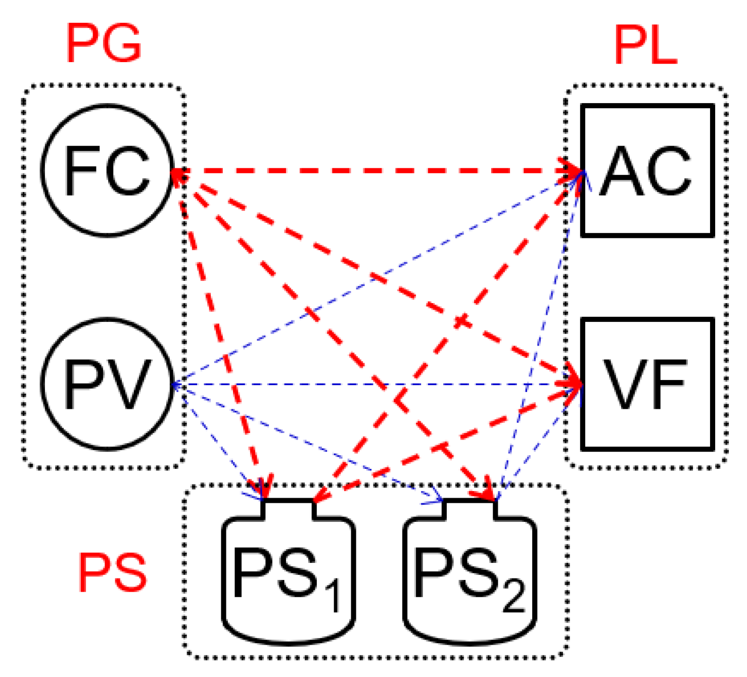
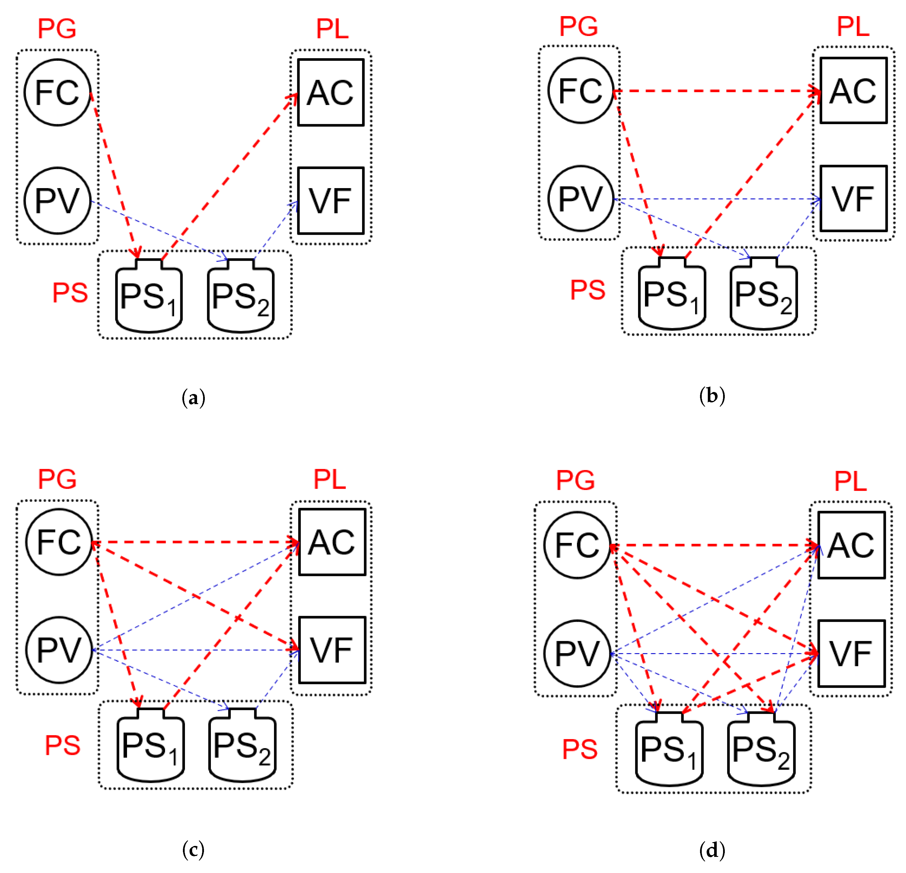
6.2. Four Different Logical Power Connections
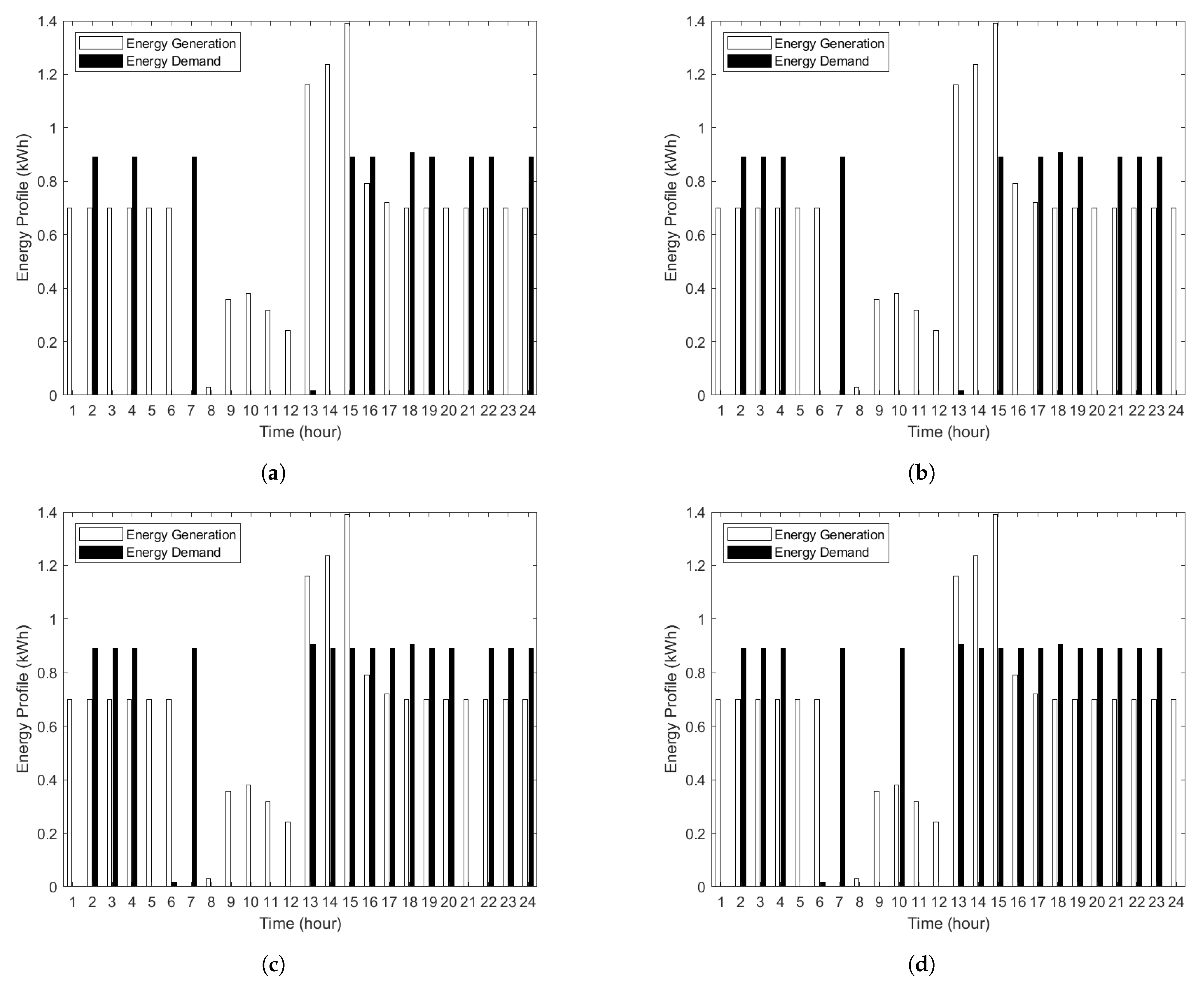
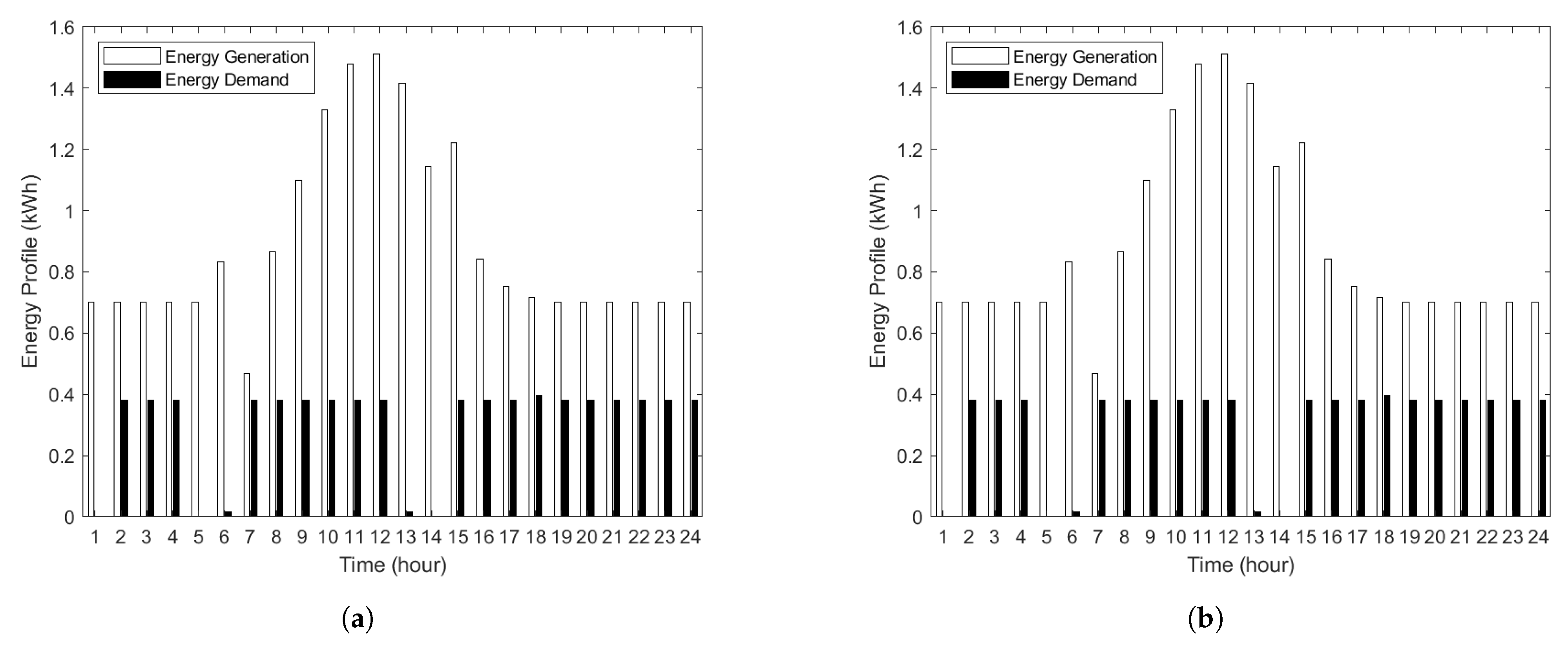
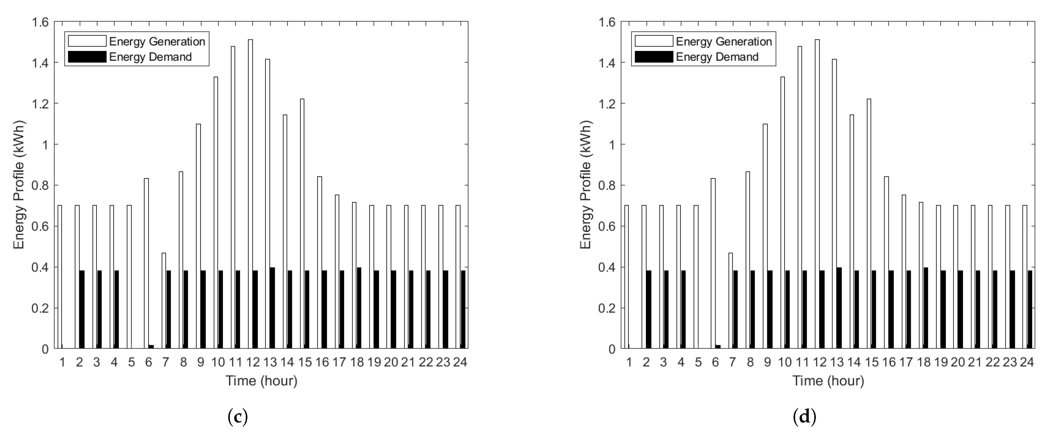
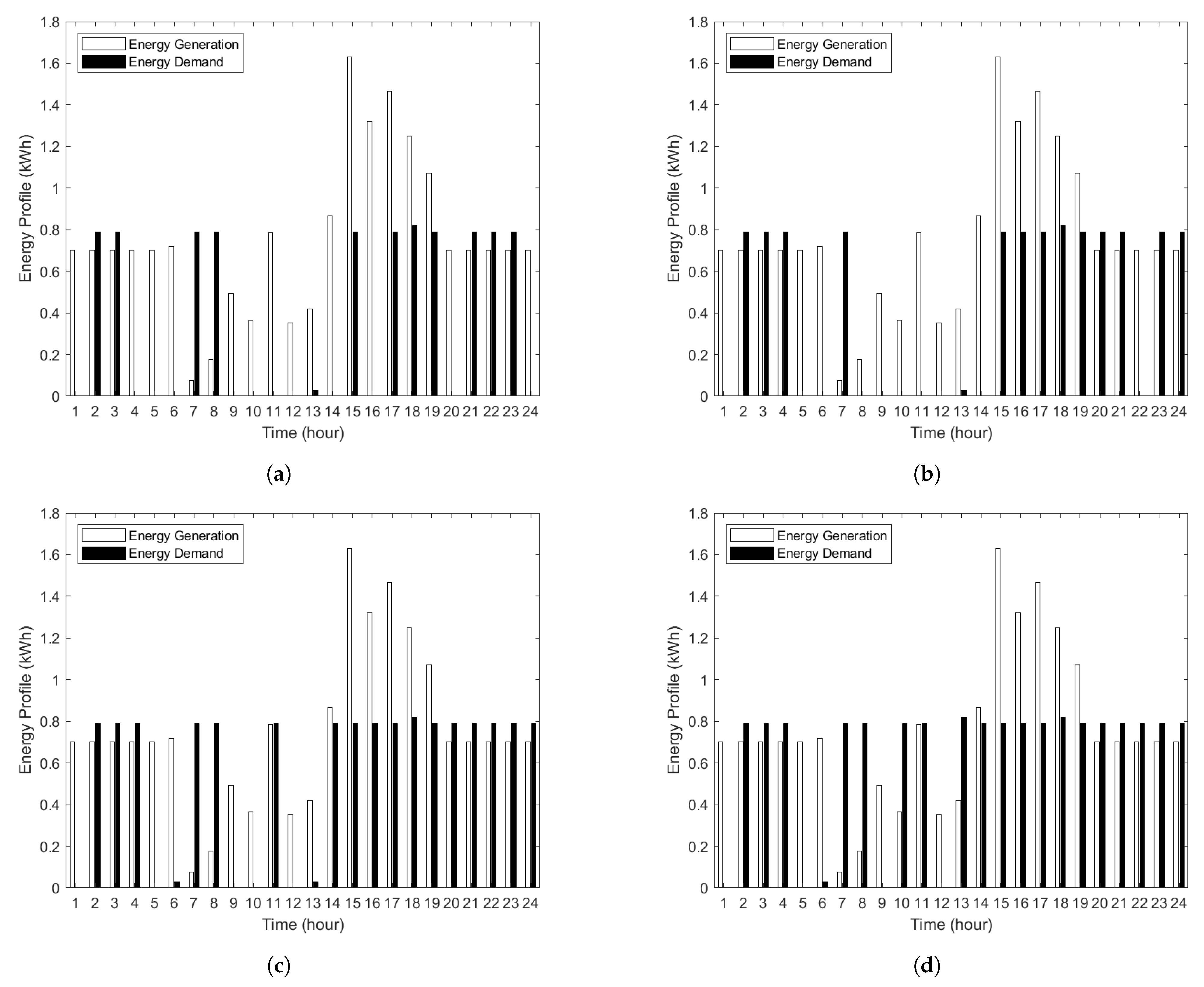
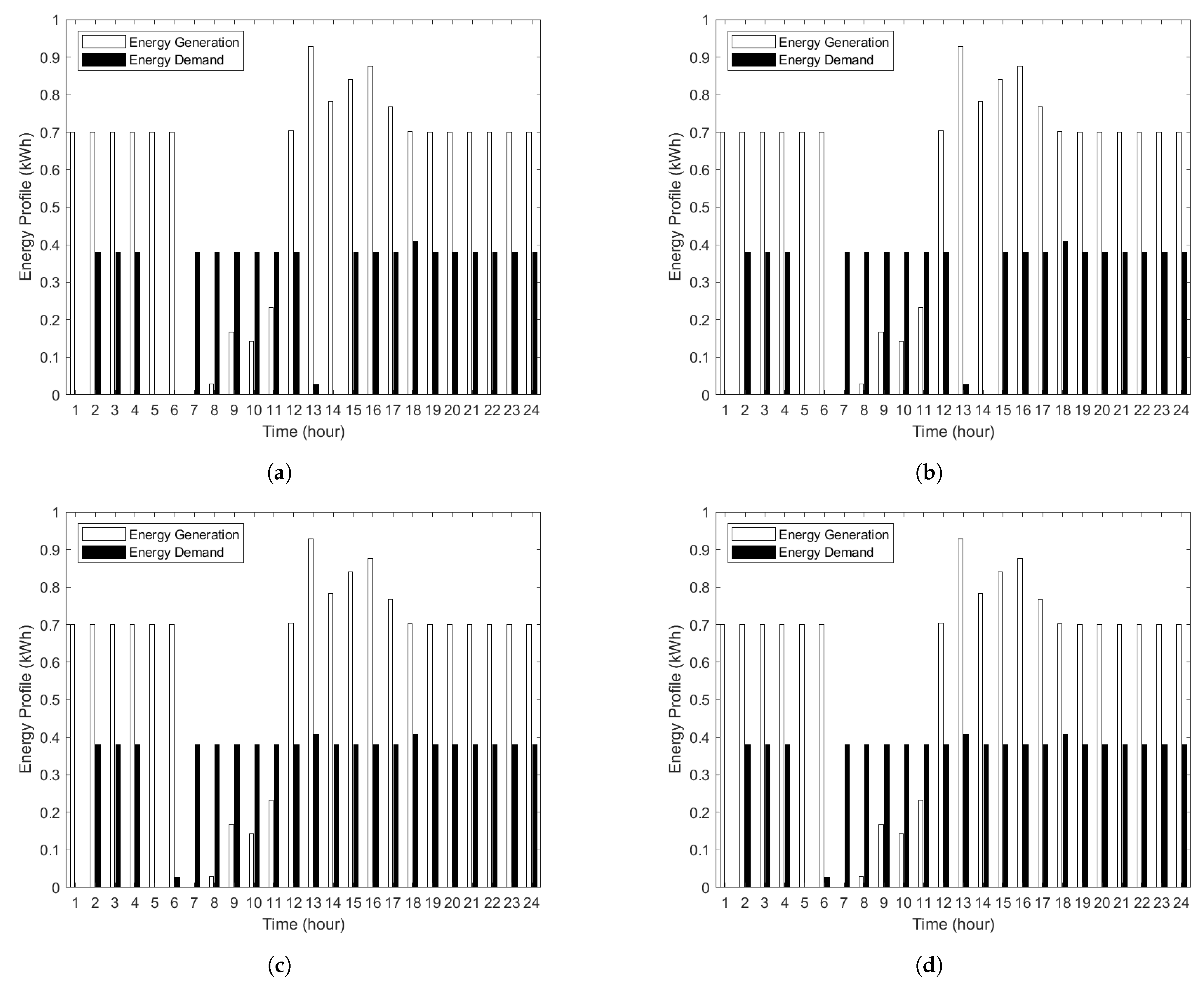
The different logical power connections shown in Figure 4 require different power-flow assignment algorithms. These four different logical power-connection scenarios can be divided into two categories based on power-flow assignment (PFA). The first category is single-load power-flow assignment (SPFA), which consists of SPFA/S and SPFA/GS to handle a single PG and supply its power to a single PL. The second category is multiple-load power-flow assignment (MPFA), which are MPFA/SG and MPFA/MG to handle multiple PGs and supply their power to multiple PLs via a single PS or multiple PSs, respectively.
In Figure 4a, a single PG always stores its power in a single PS first; then, a single PL obtains its power directly from the corresponding PS. For example, FC stores energy directly to P S 1 , and PV also directly stores energy to P S 2 . Then, P S 1 can only supply its power to AC, and P S 2 can only supply to VF. In Figure 4b for the SPFA/GS algorithm, a single PG always supplies its power directly to a single PL first; then, the remaining energy is stored in a single PS. A single PL can also obtain its power directly from the corresponding PS. In particular, FC can directly supply power to the AC, and if there is energy left, it is stored in P S 1 . PV supplies energy to the VF first and stores the remaining energy in P S 2 . P S 1 and P S 2 can still only supply a single load: AC and VF, respectively.
In Figure 4c for MPFA/SG, multiple PGs supply their power directly to all PLs first; then, the remaining energy is stored in a single PS. A single PL can only obtain its power directly from the corresponding PS. For example, FC and PV can supply power to both loads, AC and VF, at the same time. However, FC can only store its power in P S 1 , similar to PV, which can only store its power in P S 2 . When FC or PV generate insufficient power for AC or VF, P S 1 and P S 2 can discharge the stored energy to a single load: AC and VF, respectively. Finally, in Figure 4d for MPFA/MG, multiple PGs supply their power directly to all PLs first; then, the remaining energy is stored in multiple PSs equally. Any PL can obtain its power from multiple PSs. For instance, both FC and PV can provide their power to both AC and VF at the same time. The energy remaining from both FC and PV can be stored in both P S 1 and P S 2 equally. Further, both AC and VF can retrieve their energy from both P S 1 and P S 2 simultaneously.

6.3. Energy Profile

Figure 5, Figure 6, Figure 7 and Figure 8 show the energy profiles of four different PFAs in winter, spring, summer, and autumn, respectively. The different PFAs may have different energy profiles because AC and VF loads need to consume the full amount of energy in order to turn themselves on, which is the result of the amount of energy generated and the condition of the ESSs; otherwise, the load is not turned on, and the remaining energy is stored in an ESS instead. Note that t = 1 on the horizontal axis means time 0:00–1:00.
Figure 5 and Figure 7 show the energy profiles of winter and summer, respectively, which have similar demand patterns. Around 08:00–14:00, there are no PFAs that can satisfy the required demand because AC consumes such a high amount of energy that both FC and PV cannot supply enough for the entire operation time. Even MPFA/MG, with the help of both PSs, cannot satisfy all PLs during the day. However, during the operation time, the PLs in MPFA/SG and MPFA/MG are met for more hours than in SPFA/S and SPFA/GS since both PGs help supply the PLs. On the other hand, in SPFA/S and SPFA/GS, each PG can only supply one load; thus, the AC load cannot be fulfilled when FC is not generating energy even when PV generates energy sufficient for both PLs.
Spring and autumn in Figure 6 and Figure 8, respectively, show similar demand patterns. MPFA/SG and MPFA/MG can satisfy all required demands since the demand of AC in spring and autumn is less than that in winter and summer, i.e., AC consumes 380 Wh in spring and autumn, while it consumes 890 and 790 Wh in winter and summer, respectively. However, in SPFA/S and SPFA/GS, there are some hours that all PLs cannot be fulfilled, specifically 12:00–14:00. This is because each PG in SPFA/S and SPFA/GS can only supply a single load, unlike in MPFA/SG and MPFA/MG, where both PGs can provide energy to all PLs. Hence, the AC in SPFA cannot be turned on even though the overall energy generated from 12:00–14:00 is enough, since all the generated energy comes from PV and not from FC.

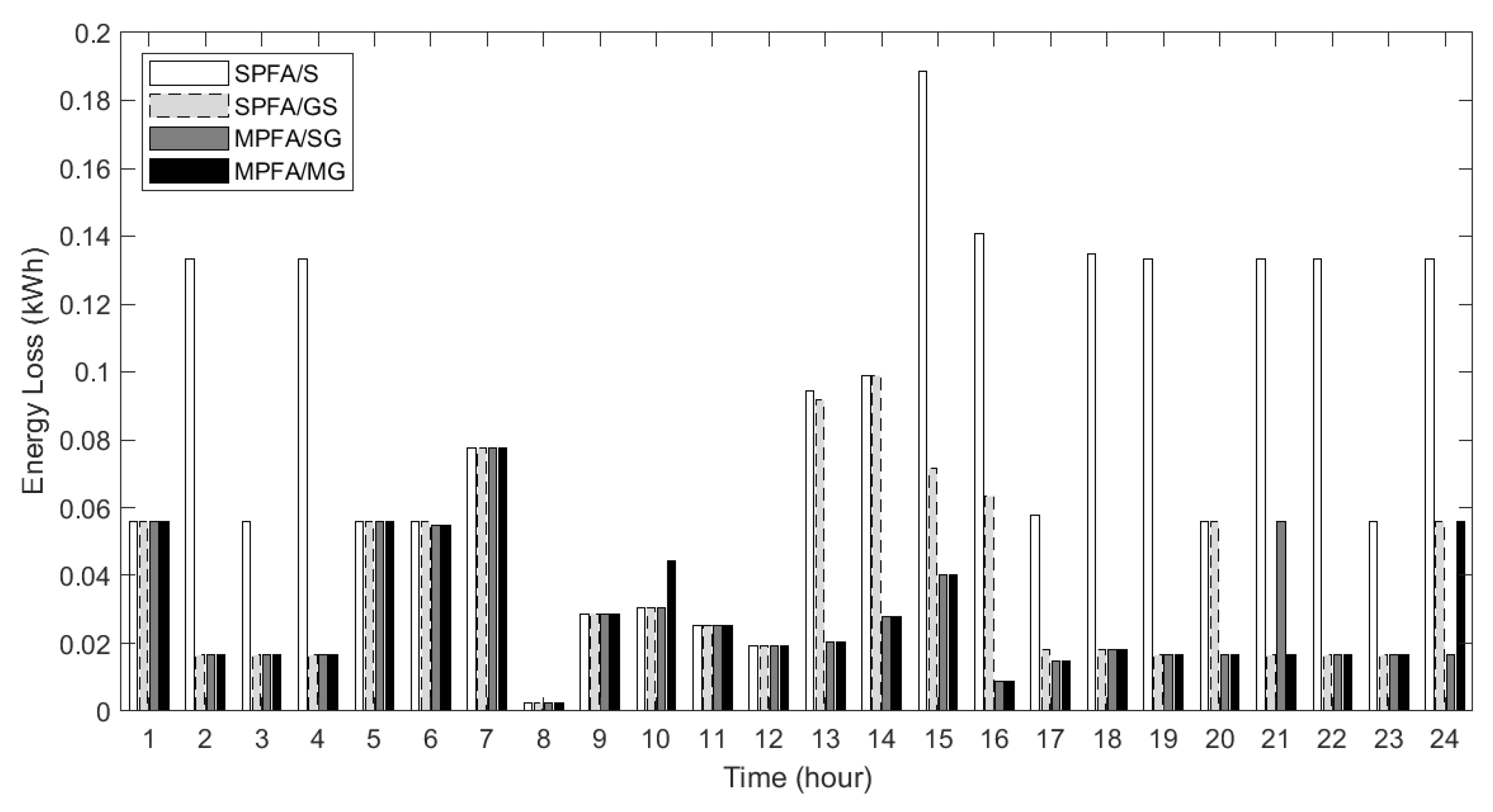
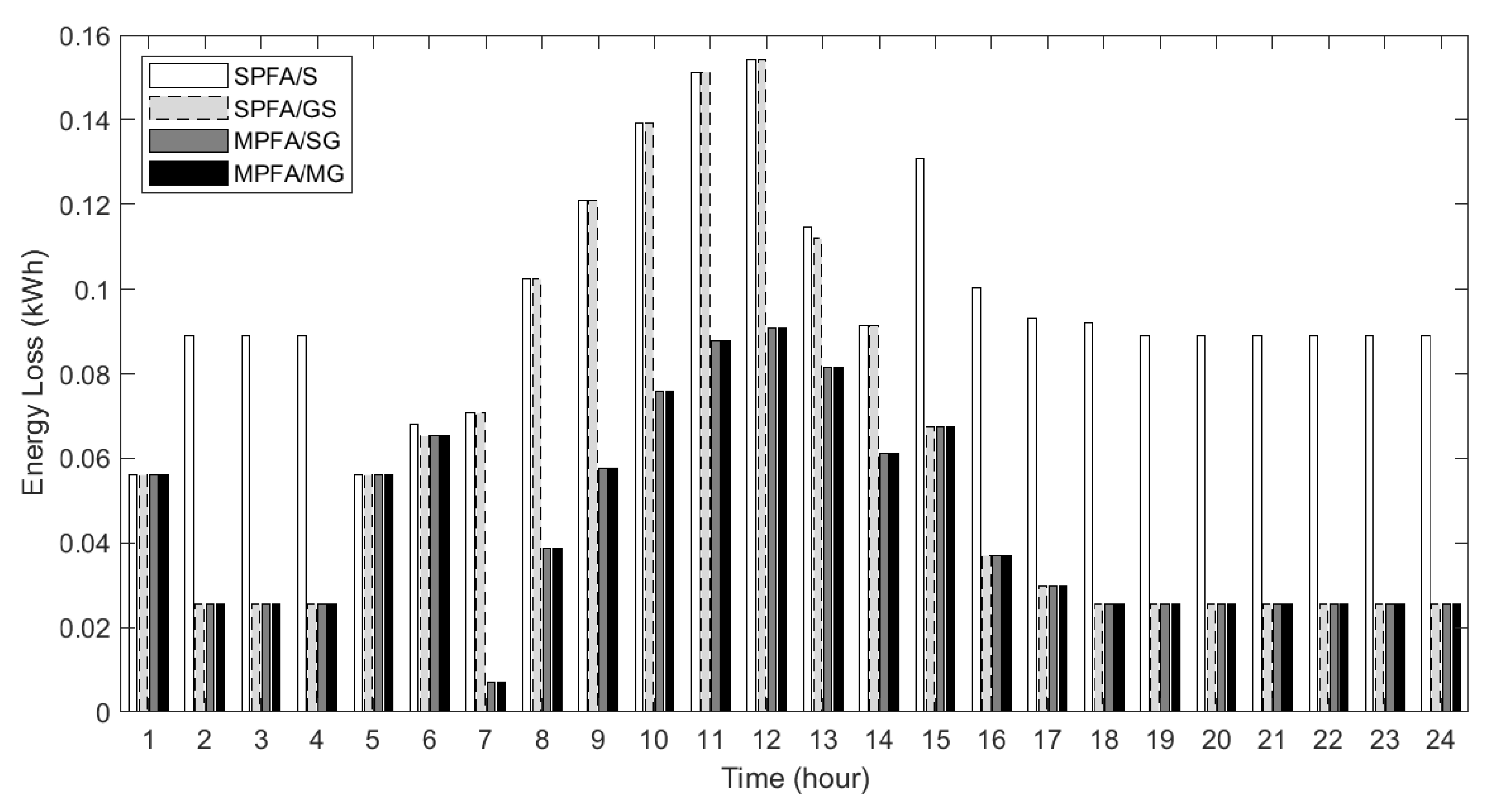
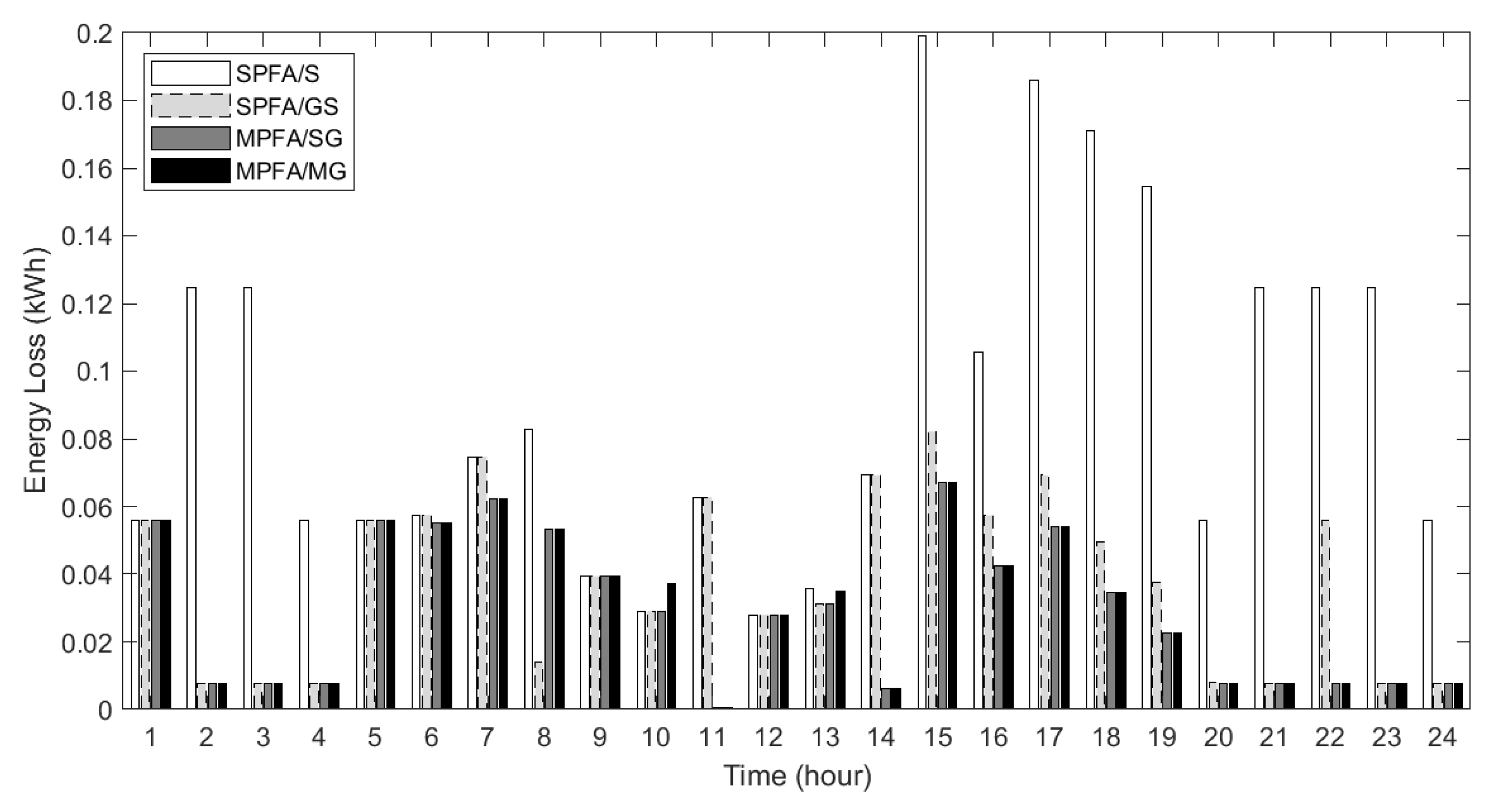
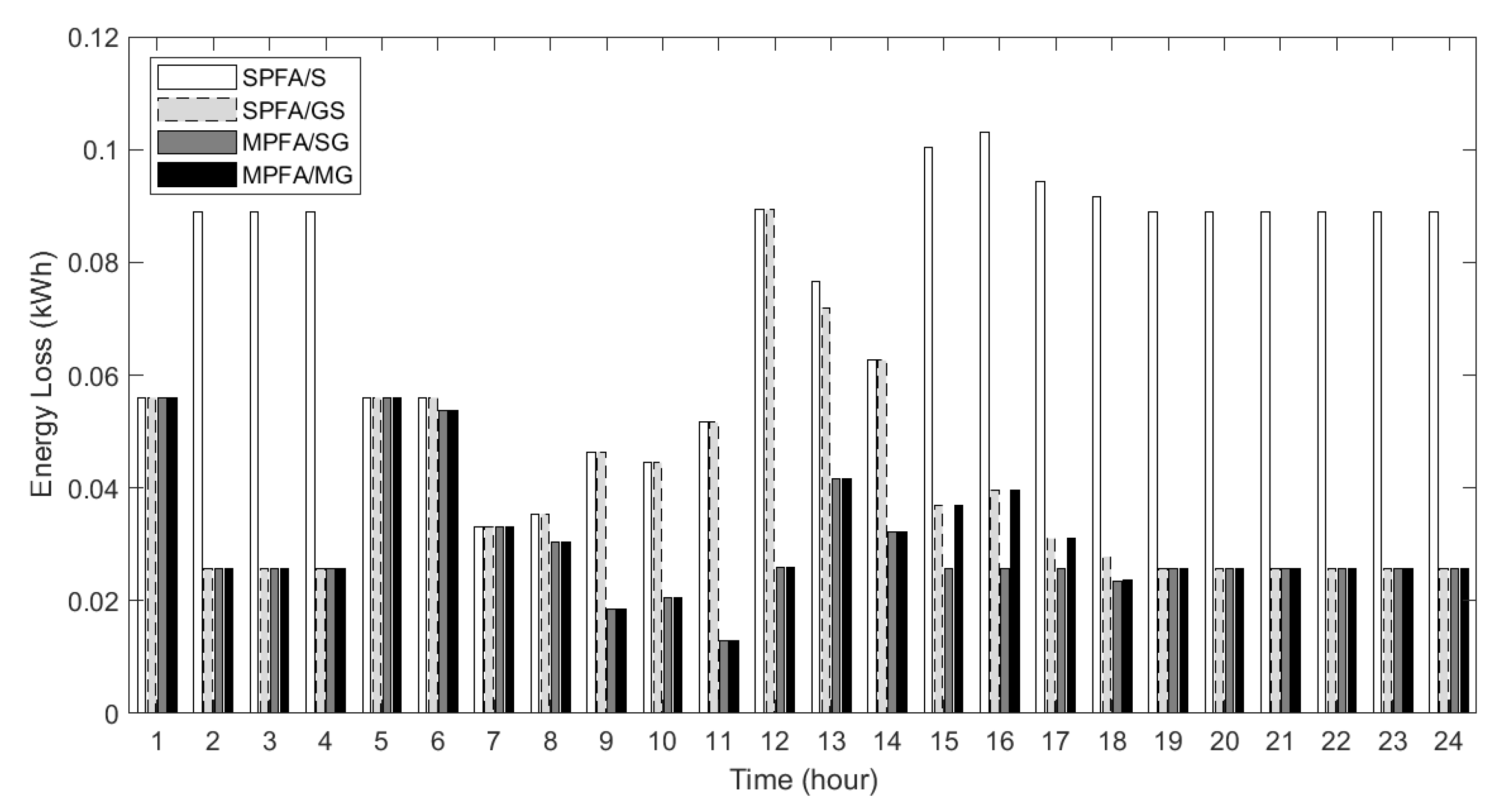
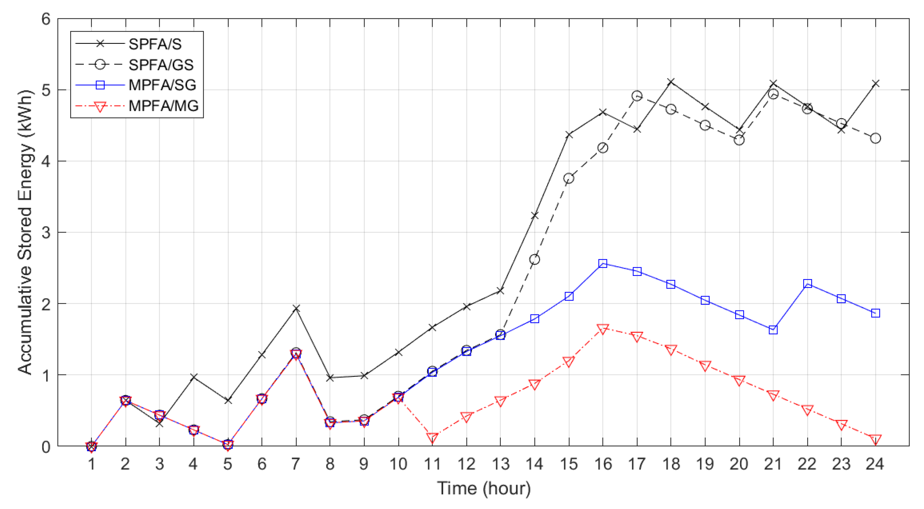
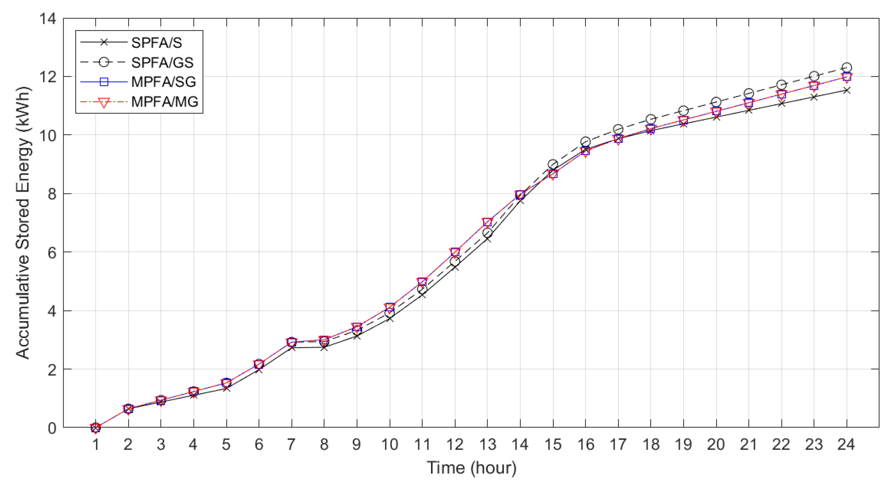
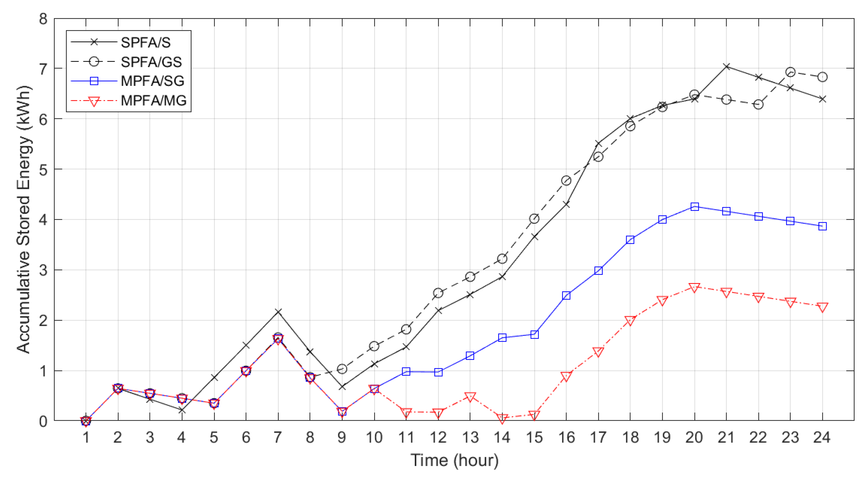
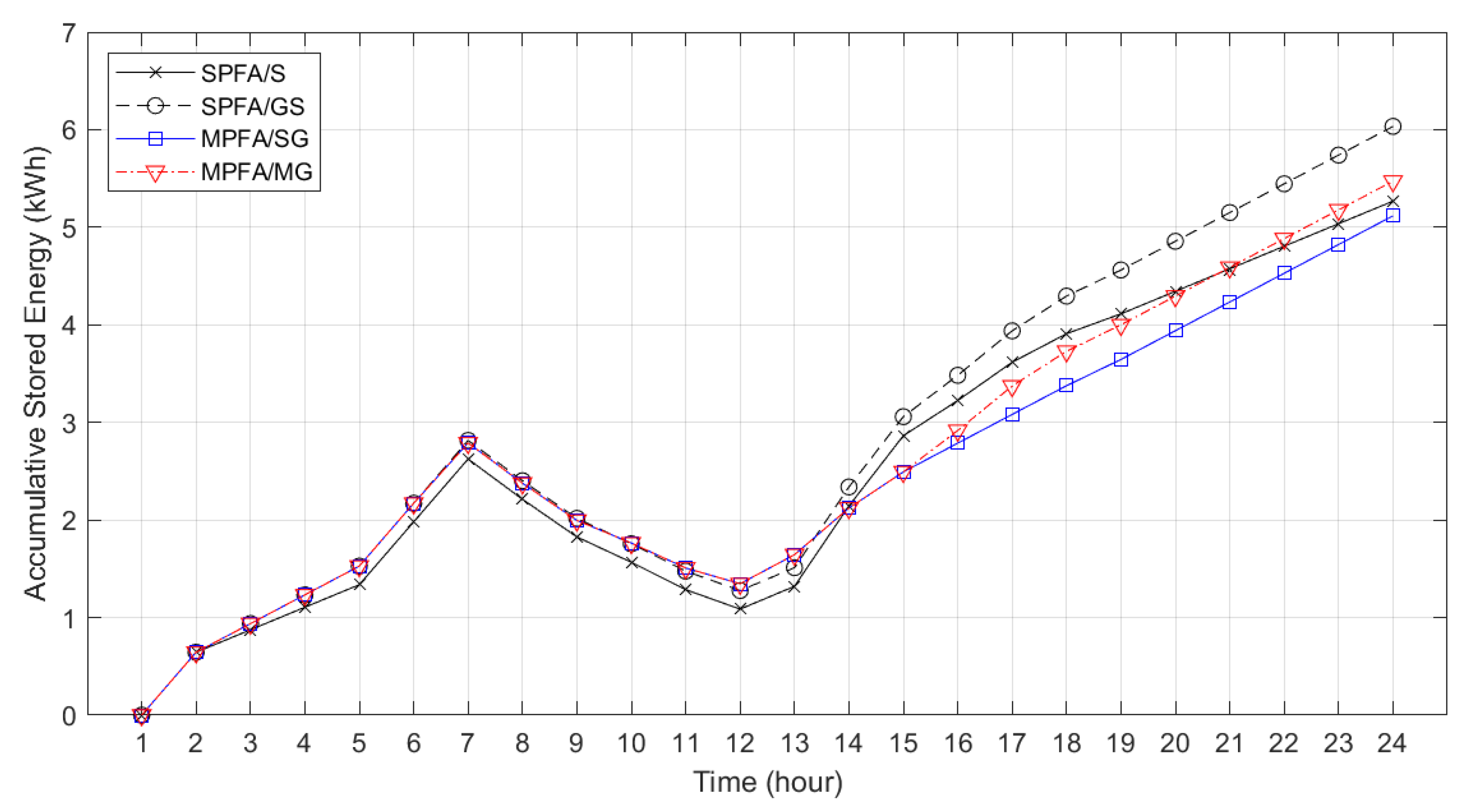
6.4. Analysis and Discussion of Energy Loss and Stored Energy of ESS

Figure 9, Figure 10, Figure 11 and Figure 12 show the energy loss of winter, spring, summer, and autumn, respectively. In SPFA/S, the PGs always store energy in PSs first; then, PSs supply energy to PLs. Thus, there are always charging and discharging losses, which results in the highest total storage energy loss for all the seasons. The energy loss results for all seasons further show that SPFA/GS comes in second place with the highest energy loss, in which the energy loss is higher than that of MPFA/SG and MPFA/MG. This is because in SPFA/GS, the PGs can only supply a single load rather than multiple loads, which results in high remaining energy charged to the PS. Hence, higher charging loss occurs. However, in MPFA/SG and MPFA/MG, the loads can receive energy from both PGs, which results in less charging loss from less surplus energy.
Table 2 shows that SPFA/S has the highest total 24-h storage energy loss from charging and discharging, as we mentioned before. In winter, the loss from MPFA/SG is the lowest and is 67% lower than that of SPFA/S. For MPFA/MG, the energy loss is very close to that of MPFA/SG and is 66.5% less than that of SPFA/S for winter. Lastly, when comparing SPFA/GS with SPFA/S, the loss in SPFA/GS is 53.7% less than that of SPFA/S for winter. Similar descriptions are applied to the remaining seasons. The results further show that spring possesses the highest energy loss in ESSs compared to the other seasons. This is because AC load in the spring consumes less energy compared to other seasons and there is high PV generation, so the energy remaining to be stored in ESSs and discharged from ESSs is higher than in the other seasons. Hence, the energy loss in the spring is the highest.
Figure 13, Figure 14, Figure 15 and Figure 16 show the stored energy in ESS of winter, spring, summer, and autumn, respectively. In winter and summer, the stored energy in Figure 13 and Figure 15, respectively, have a similar pattern. The graphs illustrate that when stored energy increases over time, we can clearly see the difference between stored energy in single-load PFAs (SPFA/S and SPFA/GS) and multiple-load PFAs (MPFA/SG and MPFA/MG). The reason is that each PG in SPFA can only supply a single load, unlike in MPFA, where each PG supplies multiple loads. Hence, there is higher surplus energy to be charged and stored in a PS for SPFA. Therefore, the stored energy of SPFA is higher than that of MPFA. Furthermore, the stored energy of MPFA/SG and MPFA/MG in winter and summer are different since PG in MPFA/SG can only charge a single PS and discharge to a single load, while PG in MPFA/MG can charge to multiple PSs, and all PSs can discharge to multiple PLs. Therefore, the stored energy in PS of MPFA/SG is higher than that of MPFA/MG.
However, for spring and autumn in Figure 14 and Figure 16, respectively, the stored energy for all PFAs have a similar pattern since PGs in spring and autumn can fulfill all or almost all of the required demand, as we discussed previously in the energy profile results. On the other hand, in winter and summer, the demands satisfied are different for each PFA, so the stored energy results are very different between each PFA over time, especially between SPFA and MPFA. The results further show that spring possesses the highest stored energy in ESS compared to other seasons since in the spring, the AC load consumes less energy and PV produces the highest generated energy compared to other seasons.
Ultimately, we can conclude that energy loss decreases when the number of connections is higher. Especially, all the generated energy should not be stored in battery storage first and supplied to loads later. Loads should be met directly first; then, the remaining energy can be stored to be supplied later. Another thing that should be pointed out is that for SPFA, if a PG is assigned to supply a PL, conversely, the situation could be the worst, since PV alone cannot fulfill the AC load for the entire operation time.

7. Conclusions

In this paper, we studied the effects of energy loss and stored energy in ESS related to the frequency of charging and discharging for all seasons for designing logical power connections for distributed power-flow assignment in a smart home. Through numerical studies, we can conclude that both MPFA/SG and MPFA/MG algorithms ensure the power generated by PGs is supplied directly to be consumed by PLs, and the remaining power from the PGs is stored in PS systems for PLs to operate at other times. As a result, both MPFA/SG and MPFA/MG achieved low energy loss with efficient energy storage during the day. The proposed DPFA algorithms can reduce energy loss up to 67% compared to power-flow assignment for which all the generated power is stored in the ESS directly (SFPA/S) in the winter. The design of a power-flow assignment that links high PG to high PL, e.g., FC to AC, is essential to ensure low energy loss for the entire energy system. We can observe that both SPFA/S and SPFA/GS cannot perform more efficiently when the logical power connections of FC to AC and PV to VF become FC to VF and PV to AC, respectively. To address this complicated design for distributed power-flow assignment, both MPFA/SG and MPFA/MG are highly recommended. The results further show that spring possesses the highest energy loss and stored energy in ESSs compared to other seasons.
Our future work will first further examine our proposed MPFA/SG and MPFA/MG algorithms when the number of PLs is large. Second, we will study the effects of charging and discharging efficiencies and storage capacity for distributed power-flow assignment. Third, we will examine power priority assignments to PLs, taking into consideration quality of energy service (QoES) in a smart home. Finally, we will consider uncertainties related to power generation and fluctuating demand in DPFA models.

Author Contributions

Concept of distributed power-flow assignment, R.K., Y.L. and S.J.; Writing—reviewing and editing, R.K., Y.L. and S.J.; Insightful guidance, Y.L., S.J., S.K. and Y.T. All authors have read and agreed to the published version of the manuscript.

Funding

This research received no external funding.

Data Availability Statement

Not applicable.

Acknowledgments

This research was supported by the Japan Advanced Institute of Science and Technology (JAIST), the National Science and Technology Development Agency (NSTDA), and the Sirindhorn International Institute of Technology (SIIT), Thammasat University (TU).

Conflicts of Interest

The authors declare no conflict of interest.

Abbreviations

The following abbreviations are used in this paper:
ACAir Conditioning
BLE Bluetooth Low Energy
CPFACentralized Power-flow Assignment
DPFADistributed Power-flow Assignment
ESSEnergy Storage System
FCFuel Cell
IoTInternet of Things
MPFAMultiple-load Power-flow Assignment
MPFA/SGMultiple-load Power-flow Assignment: Single Generator-to-Storage
MPFA/MGMultiple-load Power-flow Assignment: Multiple Generators-to-Storage
PFAPower-flow Assignment
PGPower Generator
PLPower Load
PLCPower Line Communication
PoEPower over Ethernet
PSPower Storage
PVPhotovoltaic
QoESQuality of Energy Service
RERenewable Energy Resources
SoCState of Charge
SPESingle-Pair Ethernet
SPFASingle-load Power-flow Assignment
SPFA/SSingle-load Power-flow Assignment: Storage source
SPFA/GSSingle-load Power-flow Assignment: Generator and Storage sources
VFVentilation Fan

Nomenclature

The following nomenclature is used in this paper:
mmth power generator
nnth power load
hhth power storage
M A set of power generators
N A set of power loads
H A set of power storages
E G m f ( t ) Energy generation level of mth fluctuating power generator at time t
E L n f ( t ) Energy demand level of nth fluctuating power load at time t
S o C h m i n Minimum state of charge of hth power storage
S o C h m a x Maximum state of charge of hth power storage
S o C h ( 0 ) Initial state of charge of hth power storage
S E h ( t ) Stored energy of hth power storage at time t
E S h ( t ) Charge or discharge energy of hth power storage at time t
E C h l o s s ( t ) Charging loss of hth power storage at time t
E D C h l o s s ( t ) Discharging loss of hth power storage at time t
E S S h Capacity of hth power storage
φ ( X , Y , t ) Logical power-flow connections from X to Y at time t
p g m f ( t ) Instantaneous power level of mth fluctuating power generator at time t
p l n f ( t ) Instantaneous power level of nth fluctuating power load at time t
p g m f , m i n Minimum instantaneous power level limitations of mth fluctuating power generator
p g m f , m a x Maximum instantaneous power level limitations of mth fluctuating power generator
p l n f , m i n Minimum instantaneous power level limitations of nth fluctuating power load
p l n f , m a x Maximum instantaneous power level limitations of nth fluctuating power load
p s h i n ( t ) Instantaneous input power of hth power storage at time t
p s h o u t ( t ) Instantaneous output power of hth power storage at time t
p s h i n , m i n Minimum instantaneous input power level limitations of hth power storage
p s h i n , m a x Maximum instantaneous input power level limitations of hth power storage
p s h o u t , m i n Minimum instantaneous output power level limitations of hth power storage
p s h o u t , m a x Maximum instantaneous output power level limitations of hth power storage
η c Charging efficiency of power storage
η d Discharging efficiency of power storage
R ( t ) Total remaining energy to be charged at time t
L ( t ) Total energy lacking to be discharged at time t
I ( t ) Total charging energy at time t
O ( t ) Total discharging energy at time t

References

  1. IEA. Global Energy & CO2 Status Report; International Energy Agency: Paris, France, 2018. [Google Scholar]
  2. Hung, D.Q.; Mithulananthan, N. Multiple distributed generator placement in primary distribution networks for loss reduction. IEEE Trans. Ind. Electron. 2011, 60, 1700–1708. [Google Scholar] [CrossRef]
  3. IRENA. Electricity Storage and Renewables: Costs and Markets to 2030; International Renewable Energy Agency: Abu Dhabi, United Arab Emirates, 2017; Volume 164. [Google Scholar]
  4. Harper, R. Inside the smart home: Ideas, possibilities and methods. In Inside the Smart Home; Springer: Berlin/Heidelberg, Germany, 2003; pp. 1–13. [Google Scholar]
  5. Werth, A.; Kitamura, N.; Tanaka, K. Conceptual study for open energy systems: Distributed energy network using interconnected DC nanogrids. IEEE Trans. Smart Grid 2015, 6, 1621–1630. [Google Scholar] [CrossRef]
  6. Vossos, V.; Gerber, D.L.; Gaillet-Tournier, M.; Nordman, B.; Brown, R.; Bernal Heredia, W.; Ghatpande, O.; Saha, A.; Arnold, G.; Frank, S.M. Adoption pathways for DC power distribution in buildings. Energies 2022, 15, 786. [Google Scholar] [CrossRef]
  7. Reick, B.; Konzept, A.; Kaufmann, A.; Stetter, R.; Engelmann, D. Influence of charging losses on energy consumption and CO2 emissions of battery-electric vehicles. Vehicles 2021, 3, 736–748. [Google Scholar] [CrossRef]
  8. Lim, Y.; Takano, S.; Javaid, S.; Tan, Y. Admission control scheme with balancing power negotiation algorithm for home energy management and control system. In Proceedings of the 2021 IEEE International Conference on Consumer Electronics-Taiwan (ICCE-TW), Penghu, Taiwan, 15–17 September 2021; pp. 1–2. [Google Scholar]
  9. Javaid, S.; Kaneko, M.; Tan, Y. System condition for power balancing between fluctuating and controllable devices and optimizing storage sizes. Energies 2022, 15, 1055. [Google Scholar] [CrossRef]
  10. Lim, Y.; Javaid, S.; Khwanrit, R.; Tan, Y. Seasonal storage capacity design for distributed power flow system with safe operation conditions. In Proceedings of the 2022 IEEE International Conference on Consumer Electronics-Taiwan, Taipei, Taiwan, 6–8 July 2022; pp. 577–578. [Google Scholar]
  11. Javadi, M.; Lotfi, M.; Osório, G.J.; Ashraf, A.; Nezhad, A.E.; Gough, M.; Catalão, J.P. A multi-objective model for home energy management system self-scheduling using the epsilon-constraint method. In Proceedings of the 2020 IEEE 14th International Conference on Compatibility, Power Electronics and Power Engineering (CPE-POWERENG), Setubal, Portugal, 8–10 July 2020; Volume 1, pp. 175–180. [Google Scholar]
  12. Almeida, T.; Lotfi, M.; Javadi, M.; Osório, G.J.; Catalão, J.P. Economic analysis of coordinating electric vehicle parking lots and home energy management systems. In Proceedings of the 2020 IEEE International Conference on Environment and Electrical Engineering and 2020 IEEE Industrial and Commercial Power Systems Europe (EEEIC/I&CPS Europe), Madrid, Spain, 9–12 June 2020; pp. 1–6. [Google Scholar]
  13. Javadi, M.; Nezhad, A.E.; Firouzi, K.; Besanjideh, F.; Gough, M.; Lotfi, M.; Anvari-Moghadam, A.; Catalão, J.P. Optimal operation of home energy management systems in the presence of the inverter-based heating, ventilation and air conditioning system. In Proceedings of the 2020 IEEE International Conference on Environment and Electrical Engineering and 2020 IEEE Industrial and Commercial Power Systems Europe (EEEIC/I&CPS Europe), Madrid, Spain, 9–12 June 2020; pp. 1–6. [Google Scholar]
  14. Rezaee Jordehi, A. Enhanced leader particle swarm optimisation (ELPSO): A new algorithm for optimal scheduling of home appliances in demand response programs. Artif. Intell. Rev. 2020, 53, 2043–2073. [Google Scholar] [CrossRef]
  15. Fortenbacher, P.; Mathieu, J.L.; Andersson, G. Modeling and optimal operation of distributed battery storage in low voltage grids. IEEE Trans. Power Syst. 2017, 32, 4340–4350. [Google Scholar] [CrossRef] [Green Version]
  16. Farrokhifar, M.; Grillo, S.; Tironi, E. Loss minimization in medium voltage distribution grids by optimal management of energy storage devices. In Proceedings of the 2013 IEEE Grenoble Conference, Dresden, Germany, 26–27 September 2013; pp. 1–5. [Google Scholar]
  17. Jannesar, M.R.; Sedighi, A.; Savaghebi, M.; Guerrero, J.M. Optimal placement, sizing, and daily charge/discharge of battery energy storage in low voltage distribution network with high photovoltaic penetration. Appl. Energy 2018, 226, 957–966. [Google Scholar] [CrossRef] [Green Version]
  18. Sardi, J.; Mithulananthan, N.; Hung, D.Q.; Bhumkittipich, K. Load levelling and loss reduction by ES in a primary distribution system with PV units. In Proceedings of the 2015 IEEE Innovative Smart Grid Technologies-Asia (ISGT ASIA), Bangkok, Thailand, 3–6 November 2015; pp. 1–6. [Google Scholar]
  19. Chen, Z.; Xia, B.; Mi, C.C.; Xiong, R. Loss-minimization-based charging strategy for lithium-ion battery. IEEE Trans. Ind. Appl. 2015, 51, 4121–4129. [Google Scholar] [CrossRef]
  20. Chen, Z.; Shu, X.; Sun, M.; Shen, J.; Xiao, R. Charging strategy design of lithium-ion batteries for energy loss minimization based on minimum principle. In Proceedings of the 2017 IEEE Transportation Electrification Conference and Expo, Asia-Pacific (ITEC Asia-Pacific), Harbin, China, 7–10 August 2017; pp. 1–6. [Google Scholar]
  21. Liu, K.; Hu, X.; Yang, Z.; Xie, Y.; Feng, S. Lithium-ion battery charging management considering economic costs of electrical energy loss and battery degradation. Energy Convers. Manag. 2019, 195, 167–179. [Google Scholar] [CrossRef]
  22. Schimpe, M.; Piesch, C.; Hesse, H.C.; Paß, J.; Ritter, S.; Jossen, A. Power flow distribution strategy for improved power electronics energy efficiency in battery storage systems: Development and implementation in a utility-scale system. Energies 2018, 11, 533. [Google Scholar] [CrossRef] [Green Version]
  23. Cho, S.M.; Yun, S.Y. Optimal power assignment of energy storage systems to improve the energy storage efficiency for frequency regulation. Energies 2017, 10, 2092. [Google Scholar] [CrossRef] [Green Version]
  24. Choi, J.Y.; Choi, I.S.; Ahn, G.H.; Won, D.J. Advanced power sharing method to improve the energy efficiency of multiple battery energy storages system. IEEE Trans. Smart Grid 2016, 9, 1292–1300. [Google Scholar] [CrossRef]
  25. Tewari, J. Basic Electrical Engineering; New Age International: Delhi, India, 2003. [Google Scholar]
  26. Li, X.; Hui, D.; Lai, X. Battery energy storage station (BESS)-based smoothing control of photovoltaic (PV) and wind power generation fluctuations. IEEE Trans. Sustain. Energy 2013, 4, 464–473. [Google Scholar] [CrossRef]
  27. Kularatna, N.; Gunawardane, K. Energy Storage Devices for Renewable Energy-Based Systems: Rechargeable Batteries and Supercapacitors; Academic Press: Cambridge, MA, USA, 2021. [Google Scholar]
  28. Javaid, S.; Kaneko, M.; Tan, Y. Safe operation conditions of electrical power system considering power balanceability among power generators, loads, and storage devices. Energies 2021, 14, 4460. [Google Scholar] [CrossRef]
  29. Birke, K.P. Modern Battery Engineering: A Comprehensive Introduction; World Scientific: Toh Tuck Link, Singapore, 2019. [Google Scholar]
  30. NHK Broadcasting Culture Research Institute. Time Habits of Japanese in 2005: A NHK Survey Regarding the Use of Time in the Daily Life of Japanese Citizens; Japan Broadcasting Publishers Association: Tokyo, Japan, 2006. [Google Scholar]
  31. Lim, Y.; Tang, N.T.; Makino, Y.; Teo, T.K.; Tan, Y. Simulation of solar photovoltaic and fuel cell energy system for smart community simulator. In Proceedings of the IEICE Technical Committee on Information Networks (IN), Fukuoka, Japan, 16–17 November 2017; Volume 117, pp. 1–6. [Google Scholar]
  32. Toshiba. TOSHIBA Household Fuel Cell System: ECOFARM. Available online: https://www.toshiba.co.jp/product/fc/products/pdf/TENA-chofu16-7.pdf (accessed on 19 September 2022).
Figure 1. Classification of power-flow assignment in a smart home.
Designs 06 00099 g001
Figure 2. Physical power connection of the power-flow assignment in a smart home.
Designs 06 00099 g002
Figure 3. Logical power connection of the power-flow assignment in a smart home.
Designs 06 00099 g003
Figure 4. Logical power connections of four different PFAs: (a) SPFA/S, (b) SPFA/GS, (c) MPFA/SG, and (d) MPFA/MG.
Designs 06 00099 g004
Figure 5. Energy profiles of four different PFAs in winter: (a) SPFA/S, (b) SPFA/GS, (c) MPFA/SG, and (d) MPFA/MG.
Designs 06 00099 g005
Figure 6. Energy profiles of four different PFAs in spring: (a) SPFA/S, (b) SPFA/GS, (c) MPFA/SG, and (d) MPFA/MG.
Designs 06 00099 g006aDesigns 06 00099 g006b
Figure 7. Energy profiles of four different PFAs in summer: (a) SPFA/S, (b) SPFA/GS, (c) MPFA/SG, and (d) MPFA/MG.
Designs 06 00099 g007
Figure 8. Energy profiles of four different PFAs in autumn: (a) SPFA/S, (b) SPFA/GS, (c) MPFA/SG, and (d) MPFA/MG.
Designs 06 00099 g008
Figure 9. Energy loss of PS systems in winter.
Designs 06 00099 g009
Figure 10. Energy loss of PS systems in spring.
Designs 06 00099 g010
Figure 11. Energy loss of PS systems in summer.
Designs 06 00099 g011
Figure 12. Energy loss of PS systems in autumn.
Designs 06 00099 g012
Figure 13. Accumulated stored energy of PS systems in winter.
Designs 06 00099 g013
Figure 14. Accumulated stored energy of PS systems in spring.
Designs 06 00099 g014
Figure 15. Accumulated stored energy of PS systems in summer.
Designs 06 00099 g015
Figure 16. Accumulated stored energy of PS systems in autumn.
Designs 06 00099 g016
Table 1. Energy demand of PLs.
SeasonAC (Wh)VF (Wh)
Winter89016.5
Spring38016.5
Summer79027.8
Autumn38027.8
Table 2. Total energy storage loss (kWh).
SeasonSPFA/SSPFA/GSMPFA/SGMPFA/MG
Winter2.0350.9410.6680.682
Summer2.1990.9250.7000.712
Spring2.3421.5091.0681.068
Autumn1.7980.9680.7120.742
Publisher’s Note: MDPI stays neutral with regard to jurisdictional claims in published maps and institutional affiliations.

