Article

Mechanical Properties of Parallel TDG Bamboo Laminated Columns with Tough and Grove Joints

by
Krittapat Kitiyanun
1,
Waranon Kongsong
1,
Seree Tuprakay
1,
Sirawan Ruangchuay Tuprakay
2,
Boontham Harnphanich
1,
Chaiwat Poowarakulchai
1 and
Chaleeporn Thammapornram
1,*
1
Engineering Law and Inspection, Faculty of Engineering, Ramkhamhaeng University, Huamark Sub District, Bangkok City 10240, Thailand
2
Science Program in Urban and Industrial, Environment Management of Faculty of Science and Technology, Suan Dusit University, Dusit Sub District, Bangkok City 10300, Thailand
*
Author to whom correspondence should be addressed.
Designs 2022, 6(6), 107; https://doi.org/10.3390/designs6060107
Submission received: 3 September 2022 / Revised: 18 October 2022 / Accepted: 27 October 2022 / Published: 1 November 2022

Abstract

:
The problem of bamboo’s strength depends on the length used. From past experiments, it was found that the physical properties of bamboo have thickness at the bottom and a tapered end, resulting in the strength of the bamboo in each part being different. The bottom part can resist more compression than the tip, which corresponds to the physical characteristics of bamboo. To use bamboo for main construction, such as columns, many select raw bamboo that measures approximately 3 m from the ground and is considered the strongest part. The present bamboo laminated products are limited to 2.4 m in length due to the capabilities of today’s compression machines and the factor of length as mentioned above. The column is an important infrastructure, which must have sufficient strength and capacity to solve the problem of high space. However, based on the above limitations, it is particularly important to study the connectivity of increasing column length. A wood joint is a traditional method to secure two pieces of wood together. Tongue and groove joints are most common in floorings, such as wood flooring, laminate flooring, and flooring. One of the hardest methods of securing wood is end to end of edge to edge. In order to further develop green building materials, TDG bamboo is processed into laminated columns (TDGLC). It is considered important because, in addition to increasing income for farmers, it will also enable the development of building materials to replace wood in the future. Therefore, this research demonstrates the benefits of developing locally available materials such as bamboo. To develop laminated bamboo columns for use in a structure, we chose 3–4-year-old TDG bamboo and glued it to obtain a 100 mm cross-section column in order to maximize the benefits of using TDG bamboo for real use. Test specimens are joined by tongue-groove joints to a column length of 1 m, 2 m, and 3 m by joining joints in four different areas: Top (T), middle (M), top-bottom (TB), and bottom (B), to test for compressive strength. The test results showed that TDGLC + TG at the top specimens 4L01 T–4L03 T can resist a load range of 100–65%, and for the middle specimen 4L01 M–4L03 M, the load is between 88 and 57%. At the top-bottom 4L01 TB–4L03 TB, the load is between 30 and 20%. At the bottom 4L01 B–4L03 B, the load is between 28 and 18%.

1. Introduction

Natural fibers made of lignocellulose can be found in bamboo, a valuable resource from the forest [1,2,3,4,5,6]. Full-culm bamboo has long been popular in non-structural uses such as flooring, furniture, decking, and veneer. Bamboo is expected to be a sustainable alternative to conventional structural materials such as steel and wood because prior research has shown that it is stronger than softwood and hard wood [7,8,9,10,11,12]. Bamboo’s use in Thailand has significantly expanded and includes civil engineering as columns [13,14,15] and beams [16]; however, this field is still in development. Bamboo is chosen because it is affordable, easily constructed, and readily available.
Dendrocalamus Giganteus (TDG) raw bamboo is described as being tangentially uniform [17,18,19,20] and having radially functional graded [21,22]. Numerous studies have investigated the compressive strength of laminated bamboo. Some of these studies also reported the elastic modulus in the direction of the fibers. The use of bamboo as a wood substitute has gained attention [23,24]. This material can be used to create engineered products including composites, laminated boards, and plywood due to its quick growth, availability, and appealing and distinctive appearance. References [25,26] noted that bamboo has exceptional mechanical qualities, particularly in terms of tensile strength. Thai Dendrocalamus Giganteus bamboo (TDG) developed into the main structure and [27] studied the mechanical properties of the raw material of TDG bamboo aged 3 years old in Ta Wong Pa district of Nan province, with the following results: Compression test 29.74–43.79 MPa, tensile test at 159.38–257.68 MPa, and bending test at 2.21–3.47 MPa, with an average moisture content of 16.02–16.79%. The TDG laminated column had a standard size of 50 × 50 × 200 mm [28,29,30]. The mechanical properties for the test were determined using the following wood standard tests: ASTM D 143-09 [31] and DPT 1221-51 [32,33,34,35]. The mechanical properties of laminated TDG are significantly affected by the production process. Numerous investigations have been performed on the mechanical characteristics and engineering applications of bamboo-engineered materials [36]. They used small standard size specimens to make their observations. The tongue-and-groove (TG) principle is used in many types of wood products. It is used to increase interaction and prevent movement in the normal direction, but it is still not used with any consideration to diaphragm action. This is due to a lack of knowledge and no available design model calculation. If there is a possibility to increase knowledge about TG and develop a working model, it might be possible to not only use it for boards.
Therefore, this research uses full-scale TDG laminated bamboo columns, of which the cross-sections are 4 inches, connected by the tongue and groove joint, to create columns of different lengths: 1 m, 2 m, and 3 m. We study the failure and capacity loads that the TDG laminated column with this joint connection can withstand.

2. Materials and Methods

For this research, Dendrocalamus Giganteus (TDG), a type of raw bamboo from Nan Province in Thailand, was used. Four-year-old TDG culms were chopped 3.5 m above the ground during harvest on a farm in northern Thailand. According to previous research and analysis, the compression strength of TDG bamboo columns varies depending on a number of variables, including the use of cross-sections of 100 mm, 152 mm, and 203 mm, and connection via a tongue and groove joint to create the column in various lengths, including 1 m, 2 m, and 3 m. The process of producing the column is as follows:
The preservation procedure can extend the lifespan of the material and preserve the bamboo from fungus and insects. The crucial step is drilling a hole through the bamboo clump so that water and chemicals may pass through. In this phase, we drilled above the node or placed two technical drills in the middle clumps. To decrease the amount of flour in the bamboo, we soaked it in water for a month. Then, for two weeks, we soaked it in Tim-Bor with a 7–10% concentrate to protect it from bugs and fungus. Then, the bamboo was dried in a solar kiln house for 15 days and we checked that the moisture content of the wood was not more than 12%.
Forming Columns: To create columns with a cross section of 100 mm, the strips were formed with PVA glue and clamped together. The steps in this technique were as follows: Cut the bamboo to 3.5 m in length and cut it into strips with a strip machine; after that, plan all the strips until they are smooth and the same size. The strip was dressed into strips with the final dimensions of 3500 mm (length) × 20 mm (width) × 4 mm (thickness). The clamping procedure compressed the strip to ensure a column size of 4 inches in different lengths of 1–3 m, with the tongue and groove joint at different locations as shown in Figure 1, Figure 2, Figure 3, Figure 4 and Figure 5.
The mechanical performance of the laminated TDG column is shown in Table 1. This is a test result from research on the mechanical properties of laminated bamboo based on 105 test specimens with reference test sizes from ASTM and Thai woodworking standards. With a cross-section of 20 mm and a length of 250 mm, the results from the mean, summarizing the important test results, are shown in Table 1.

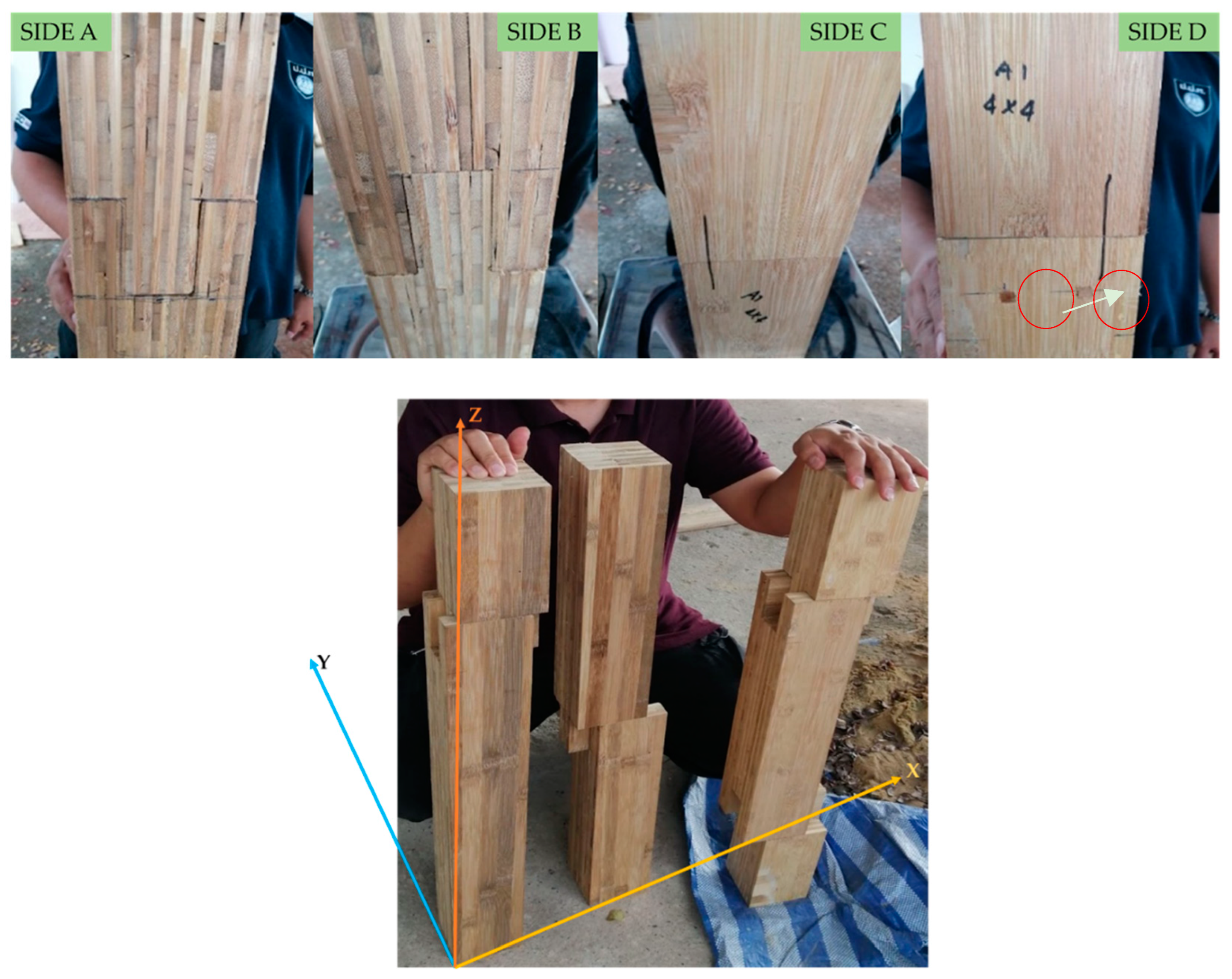
2.1. Code and Specimens

TDGLC + TG is divided into two parts, with the groove being 100 mm deep and the tongue 76 mm wide, as shown in Figure 1. Figure 2 illustrates the four sides of the column. The tongue and groove joint connection is made with the glue and a wooden dowel.
Four groups of specimens were built, taking into account the length and compression directions; more information is shown in Table 2. The group under compression parallel to the grain is designated as “4 + L01 + B”; the number 4 denotes the cross-section, the number 01 denotes the length of 1 m, and the letter B denotes the location of the joint; B = bottom, M = middle, TB = top + bottom, and T = top, as illustrated in Figure 3. The “length” is also the direction of compression. There were 18 identical specimens in each group for a total of 72 pieces.
The specimens according to the factors affecting the compressive strength of TDGLC + TG are as follows: The actual size of the column cross-section, 100 mm; different lengths of 1 m, 2 m, and 3 m; and joined at different locations as follows: Top (T), middle (M), top + bottom (TB), and bottom (B). The four sides of the specimen are shown in Figure 2 as follows: Side A and side B are on the y-axis, and side C and side D are on the x-axis.
The analysis method formulated the differential equation of equilibrium by assuming a trail displacement function to determine constants of function using the Galerkins formula.
a b W i ( x ) R ( x ) d ( x ) = 0
We determined the unknown displacements and thus the unknown strains and stress
A E 2 U x 2 + P 0
To modify the graphics to produce curves with Bezier Curves, we defined the control point used a cubic Bezier curve defined by 4 control points
x ( u ) = ( 1 u ) 3 x 0 + 3 ( 1 u ) 2 u x 1 + 3 ( 1 u ) u 2 x 2 + u 3 x 3 0 u 1
To modify the graphics to produce curves with Bezier Curves, we defined the control point used a cubic Bezier curve defined by four control points. [37,38]

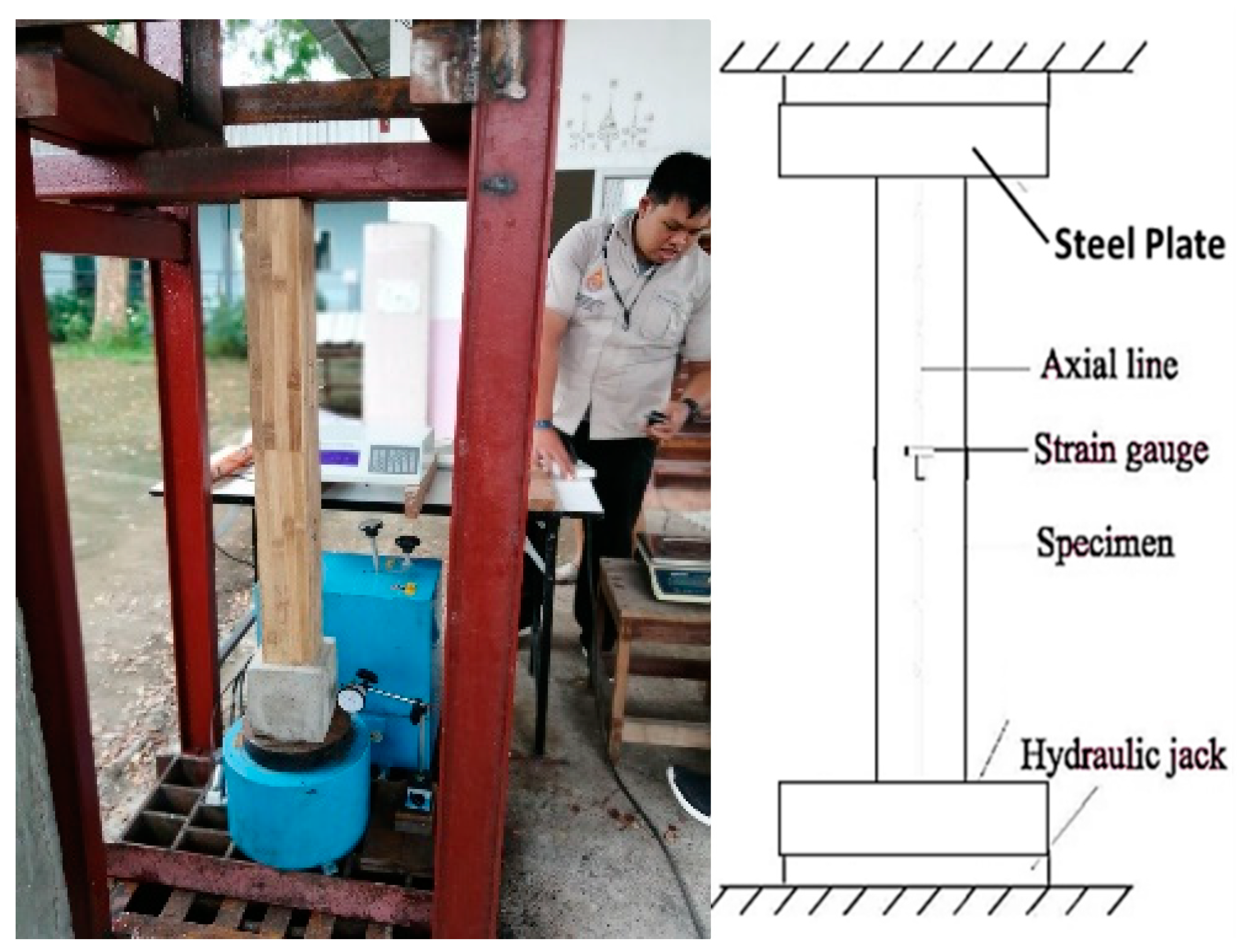
2.2. Experimental Tests

The test setup is depicted in Figure 4. One strain gauge, which was adhered to the middle side surface of the specimens as indicated in Figure 4, was used to measure the displacement of the specimen along its axial direction. A compression testing device with a 2000–3000 kN capacity was used for the test. The Digital Display TTR-080G reads the test. The maximum loading time allowed is between 8 and 10 min. Prior to the proportional limit, the load application switched from load control during the elastic stage to displacement control. After a linear ramp-up of the load to 100 kN at a rate of 1.0 kN/s, the testing method was switched to displacement control.

3. Test Results and Discussion

3.1. Failure Mode

In the study of the failure of TDGLC + TG specimens, the following test results were found.

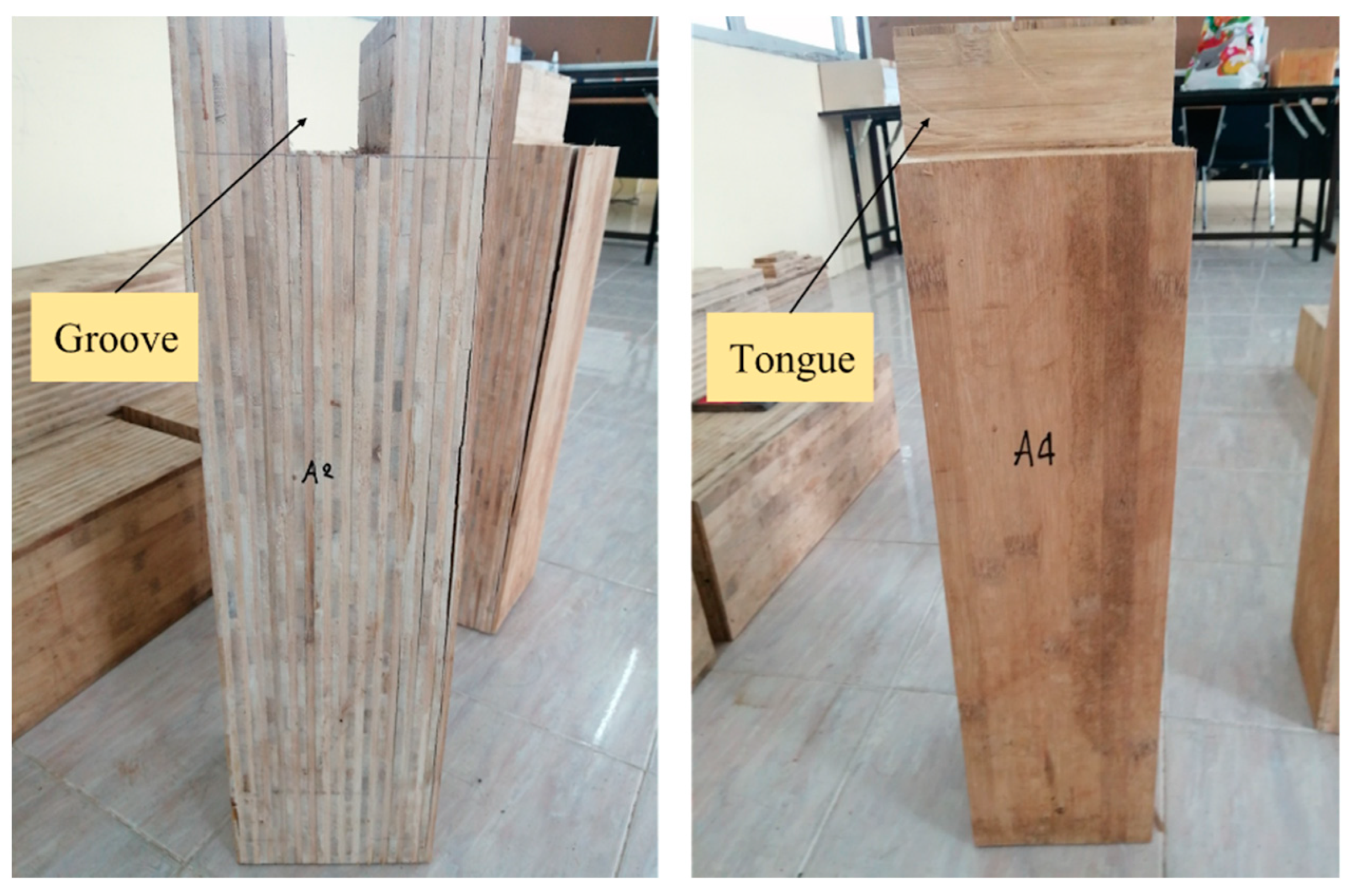
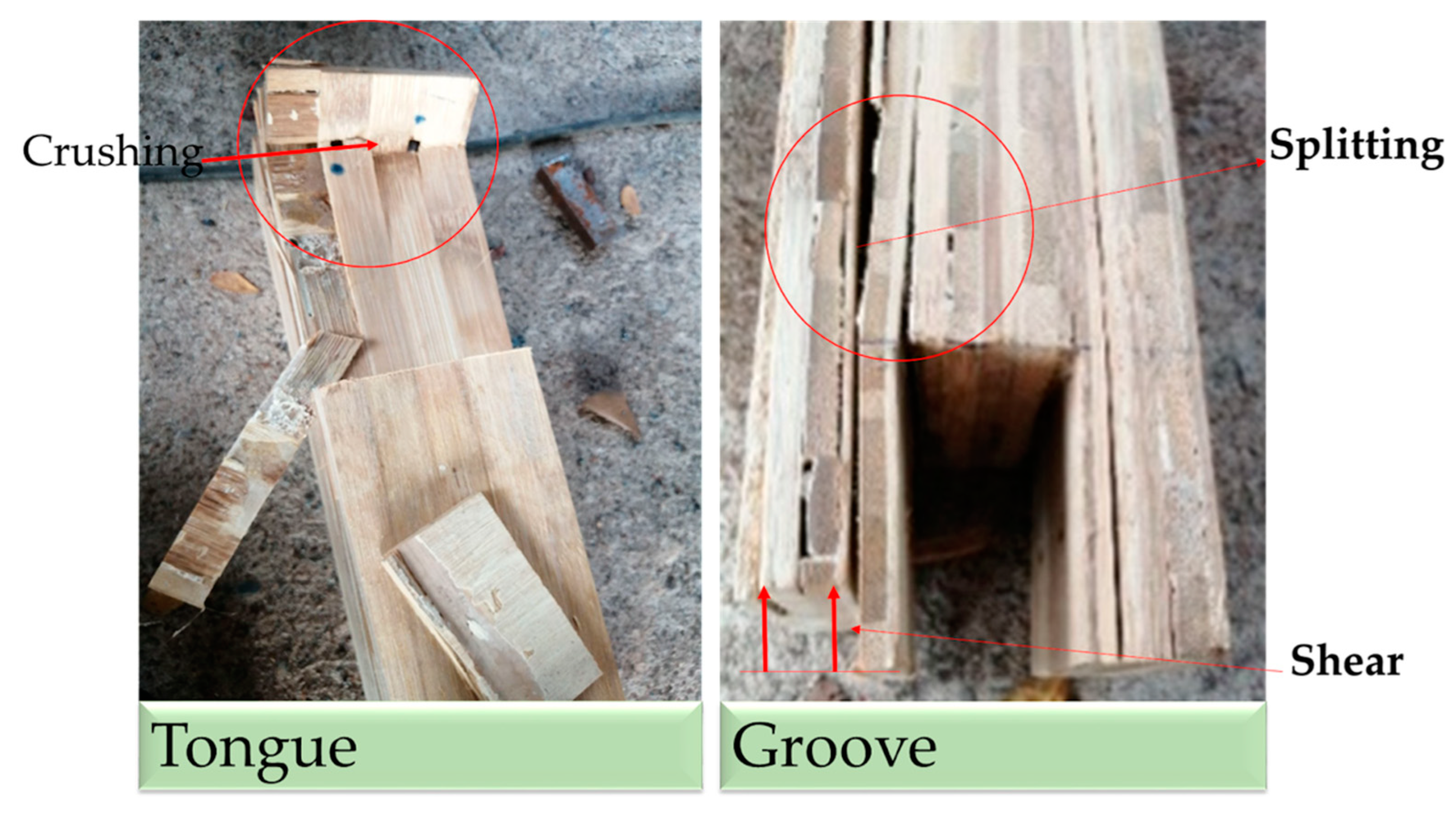
3.1.1. At the Tongue and Groove

Most of the specimens fail in Crushing Mode, which can see in the horizontal line shown in the red circle, and the tearing of TDG bamboo pieces is caused by the adhesion of glue. Regarding the deformation of bamboo that occurred in the groove, the test found that most of the disasters can be divided into two types: Splitting mode and shear mode.
We enlarged the image to study the damage occurring within the wood. After compression, the specimens at the connection joints were cut for study. The glue failure can be divided into three types as shown in Figure 5. Most of the TDG bamboo laminated columns joined with a tongue and groove joint (TDGLC + TG) failed via splitting caused by three types of glue failure, as follows: Adhesive failure (ADH), cohesive failure (CO), and light-fiber-tear failure (LFT).

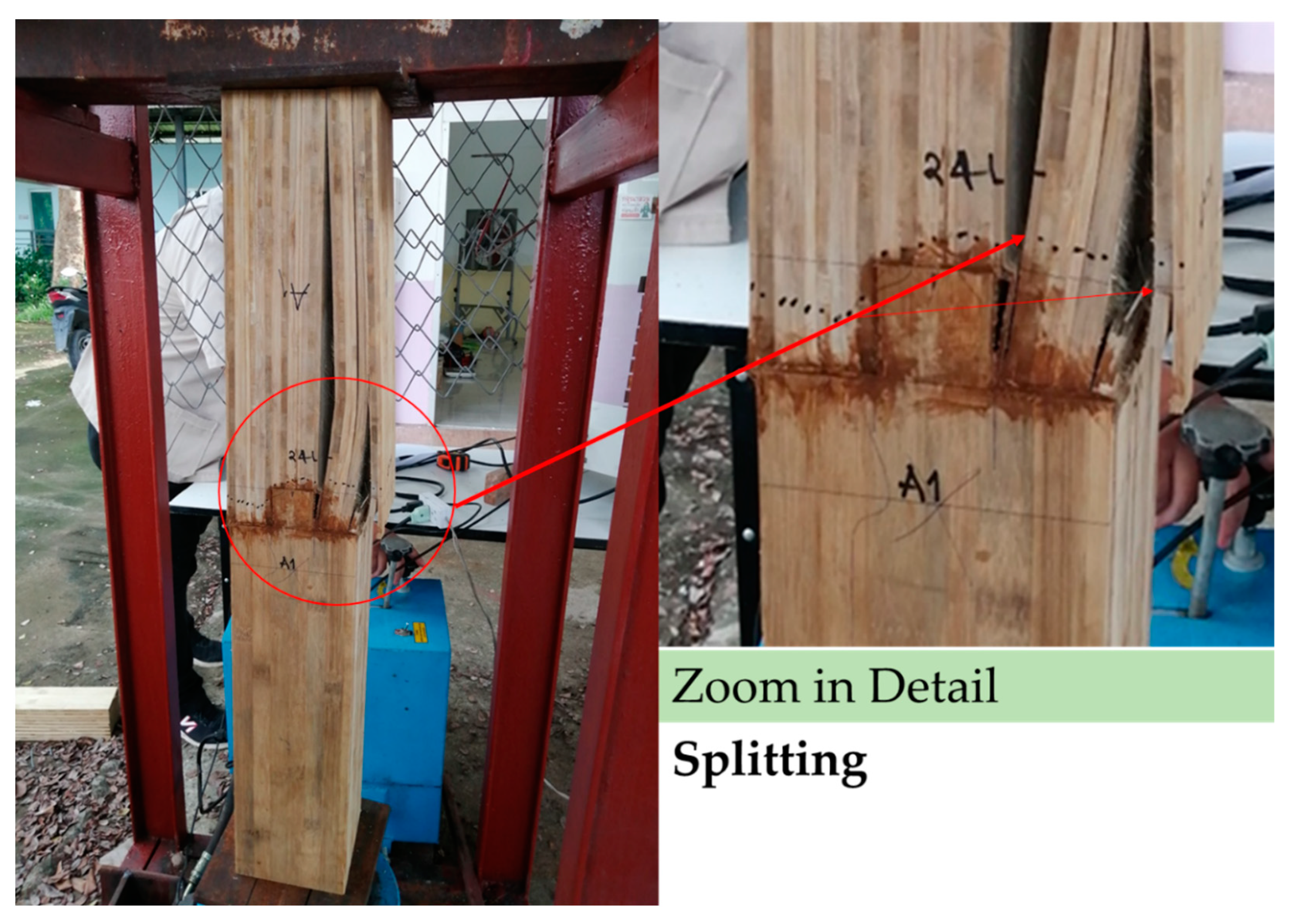
3.1.2. Splitting Mode

TDG LC + TG joined at the top (T), middle (M), and bottom (b) the majority of the failure modes occurred along the glue lines on TDGLC + TG in the groove section. Most of the separation is deflected, as shown in Figure 6. The red circle shows the deflection; the part adjacent to the groove splits longer than the part located at a further distance away from the groove. The tearing occurred on the side of the groove and split in a long straight line, causing a separate small pillar piece.

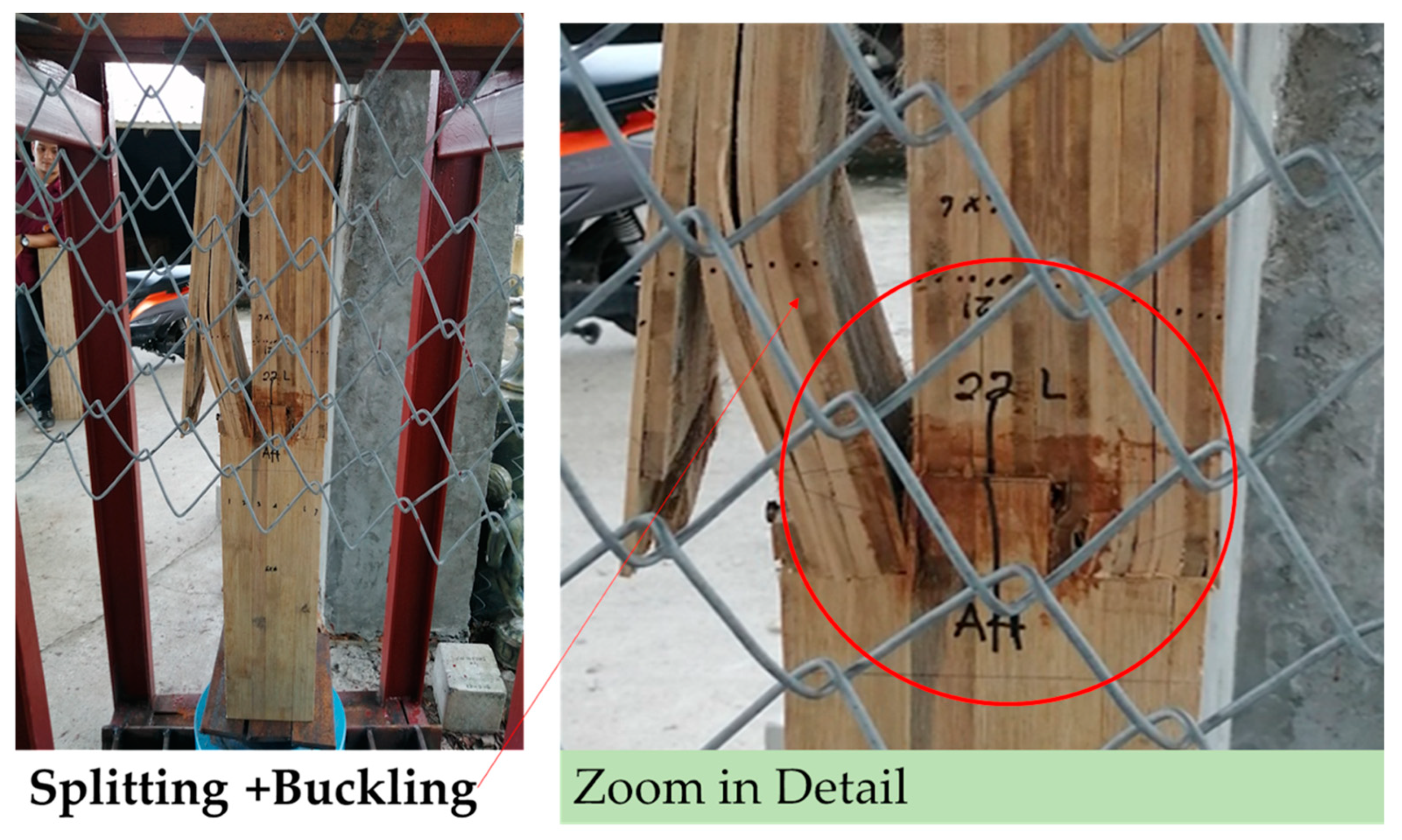
3.1.3. Splitting + Buckling Mode

The Splitting + Buckling Mode type failure mode of the test specimen is caused by tearing along the glue line in a long straight line and the formation of a small pillar. The small TDGCL + TG was subjected to compression, thus causing splitting and buckling. As shown in Figure 7, most of the TDGCL + TG was still a normal shape.

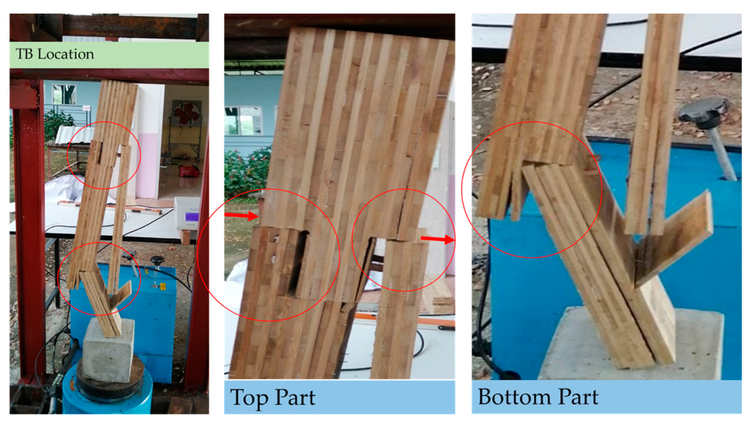
3.1.4. Type at Location TB

TDGLC + TG specimens with top (T) and bottom (TB) joins failed by splitting the glue into a long line in splitting mode. Most of the failures occurred due to ruptures near the groove, causing separation of the column as shown in Figure 8. The part that came off was pushed. The bottom tongue separated into three pieces, causing the lower part of the columns to no longer be strong, causing an angle of inclination of the columns.
A summary of the TDGLC + TG’s test results can be classified into the following important parts:
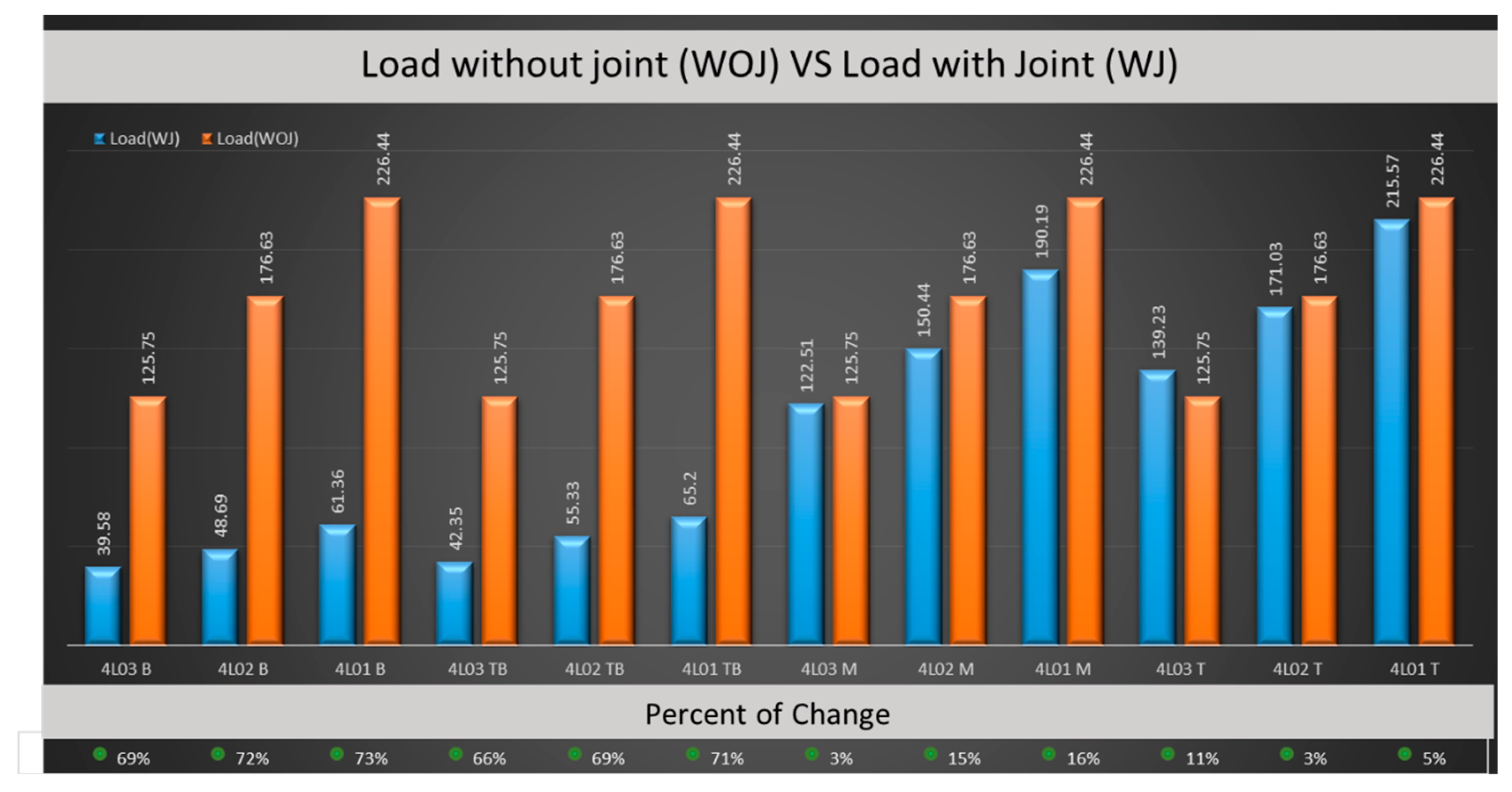
  • The failure of TDGLC + TG specimens with top and bottom joining (TB) had the least compressive strength due to the column being cut to connect numerous parts, which will cause a reduction in the strength of the column.
  • The failure of TDGLC + TG specimens joined at the bottom (B) had the least compressive strength due to the column joint being closest to the compression force and the TDGLC + TC losing strength quickly.
From the two reasons above, it can be concluded that the increased number of joints affects the strength of the column and the distance from the force to the joint. If the distance from the force is short, the failure occurs faster.
A summary of test results and the failure of all test specimens is shown in Table 3.

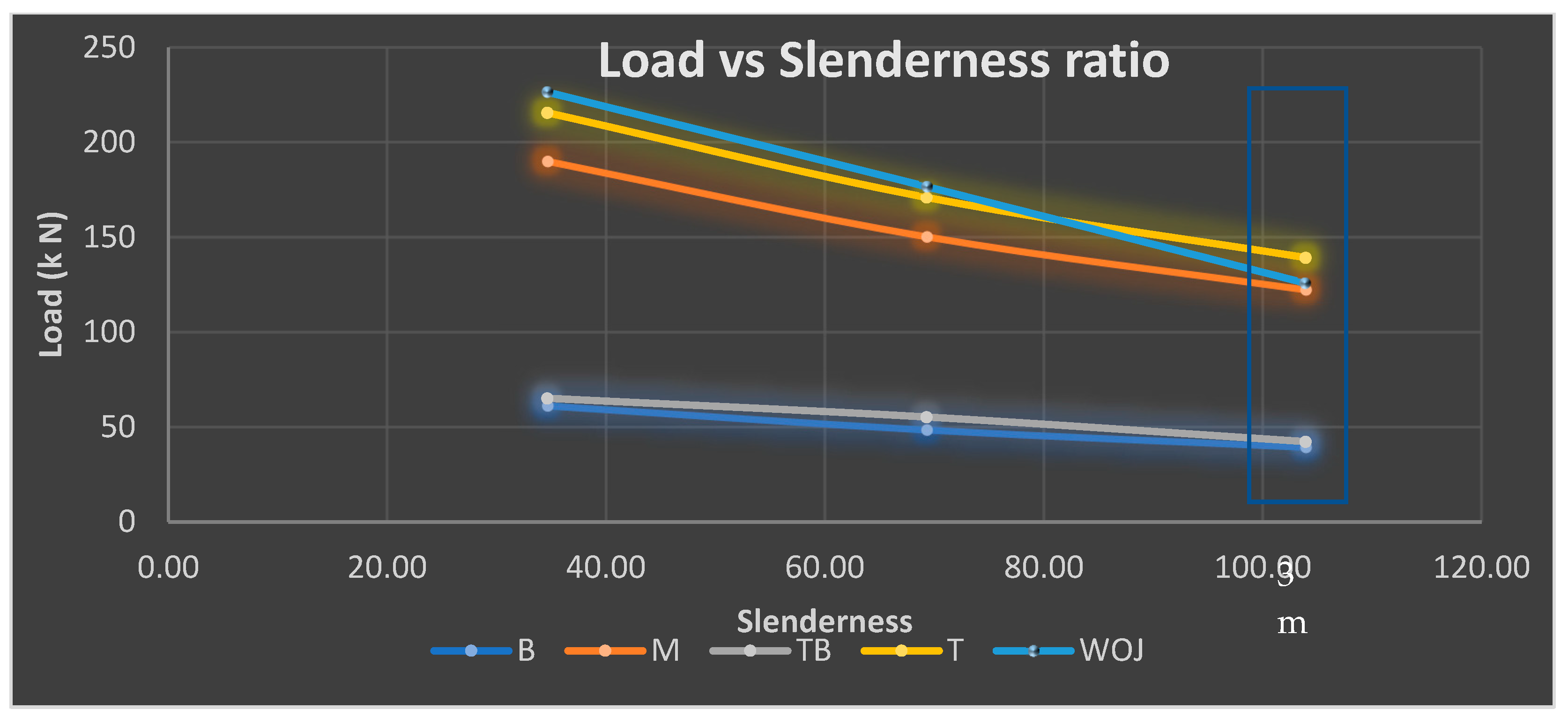
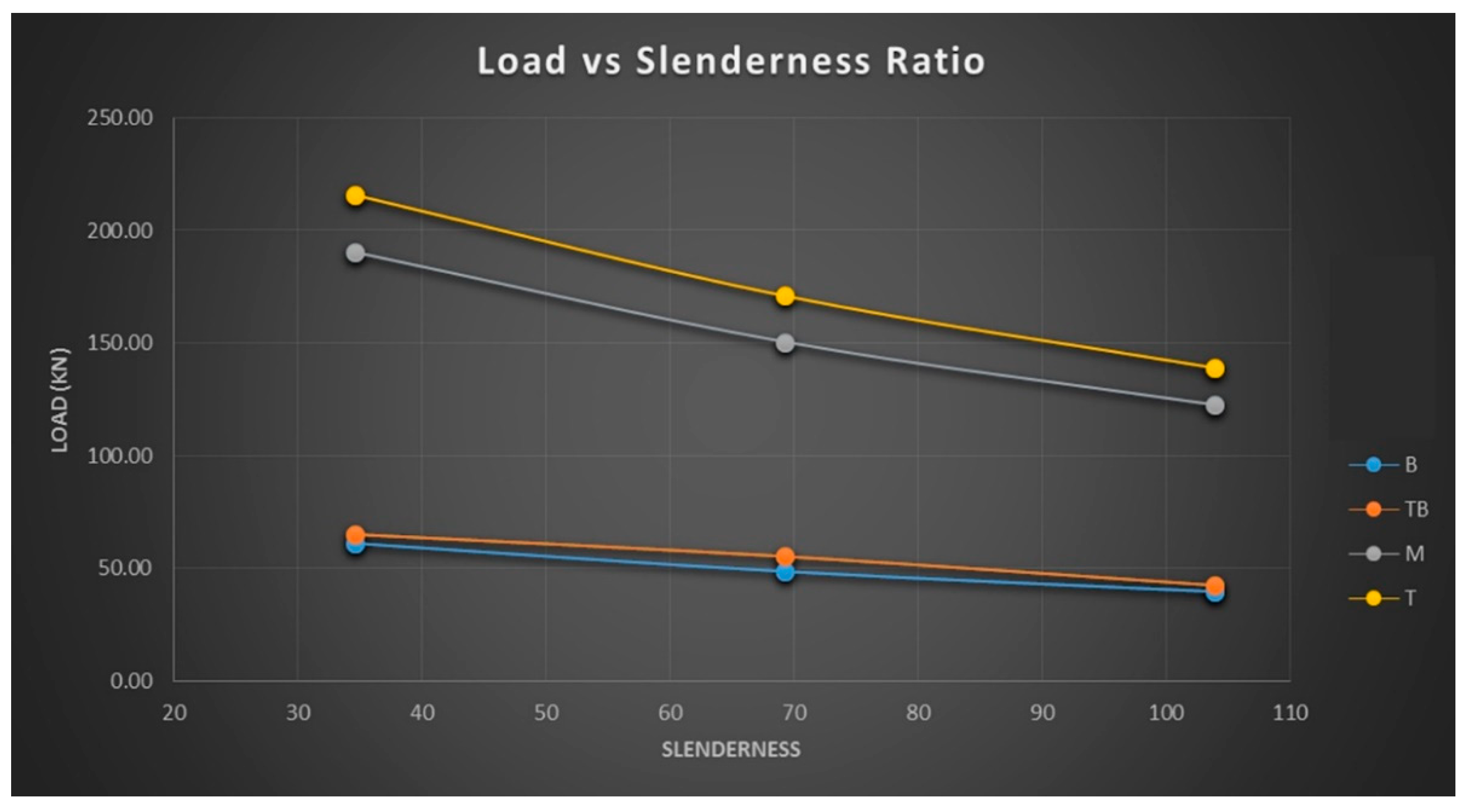
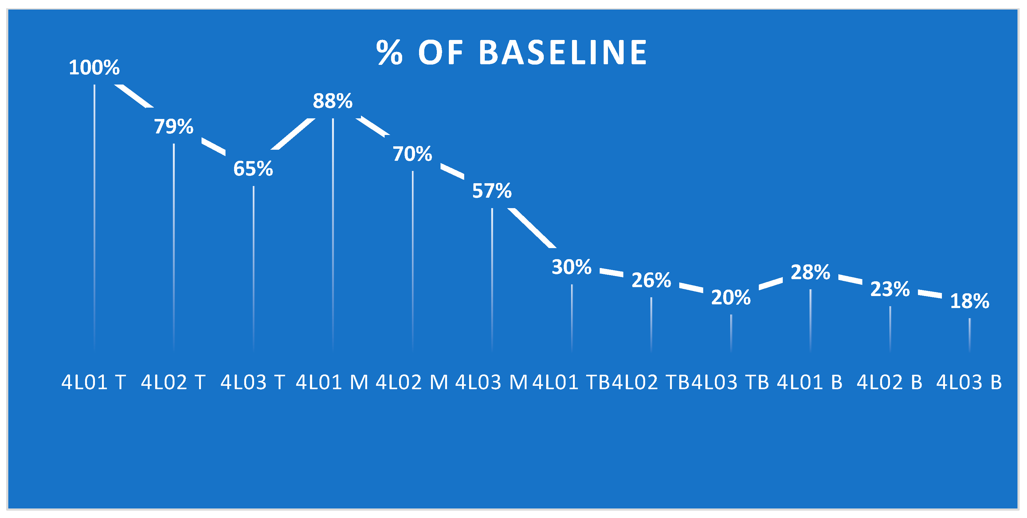
3.2. Ultimate Load Capacity and Slenderness Ratio

The ultimate load capacity for specimens 4L01–40L3 B, which were joined at the bottom location with a tongue and groove (TG), can be expressed by Equation (1). The final load capacity decreased significantly as the slenderness ratio rose, as shown by Equation (1) and illustrated in Figure 8. According to a regression analysis, Equation (1) can be used to express the maximum capacity and stress and strain analysis as shown in Figure 9. From the graph of the relationship between the load and slenderness ratio, it was found that specimens with high loads had low slenderness values, as shown in Figure 9.
The TDGLC + TG specimens were analyzed to determine the relationship between the load and slenderness ratio by using the regression method to find the equation as follows: TDGLC + TG at the bottom (B) can expressed by Equation (1), at the top-bottom (TB) by Equation (2), at the middle (M) by Equation (3), and at the top (T) by Equation (4)
P = 0.0015   λ 2 0.5197   λ + 77.581
P = 0.0013   λ 2 0.1505   λ + 71.967
P = 0.0049   λ 2 1.6596   λ + 241.76
P = 0.0053   λ 2 1.8374   λ + 272.85
where λ is
λ = L / I / A
where L is length of the column (m); I and A are the moment of Inertia and area (m4) of the column cross-section (m2).

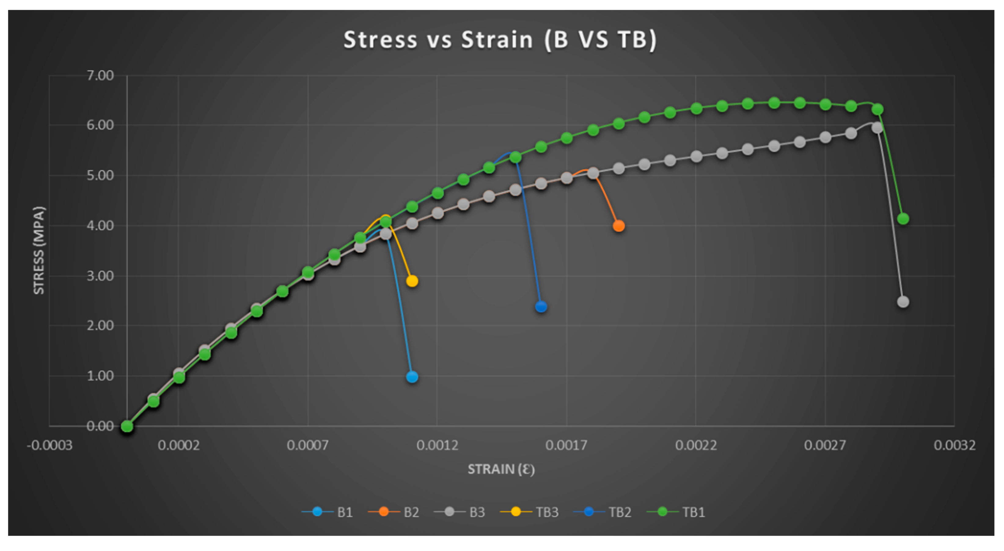
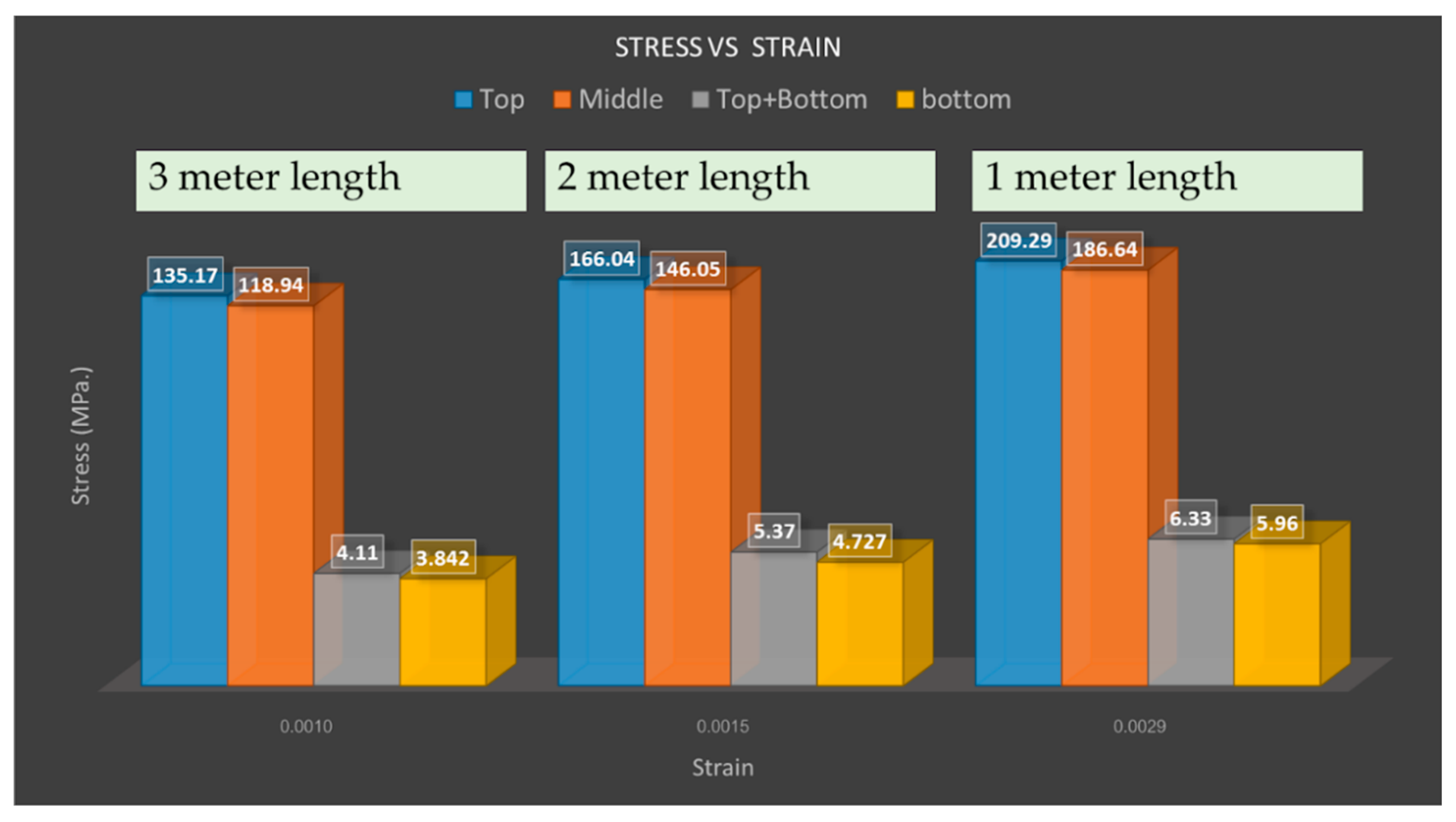
3.3. The Relationship between Stress and Strain

3.3.1. TDGLC + TG at T and B

The test results are shown in Figure 10. Regarding the relationship between stress and strain, the test results demonstrate that as the level of stress increase, so does the strain.
In this test, for different locations of the joint and different specimen lengths, B1–B3 and TB1–TB3 are tested. Different stress–strain curves were observed for TDGCL + TG at different locations, at the bottom (B) and top-bottom (TB). The TB location is slightly different from that of B. The test results are shown in Figure 10 with the following details:
  • Test results (stress, strain) are in descending order: B1 (5.96, 0.0029), B2 (4.73, 0.0015), and B3 (3.84, 0.0010) are the points.
  • Test results (stress, strain) are in descending order: TB1 (6.33, 0.0029), TB2 (5.37, 0.0015), and TB3 (4.11, 0.0010) are the points.
Regarding the relationship between stress and strain, the test results demonstrate that as the level of stress increases, so does the strain.

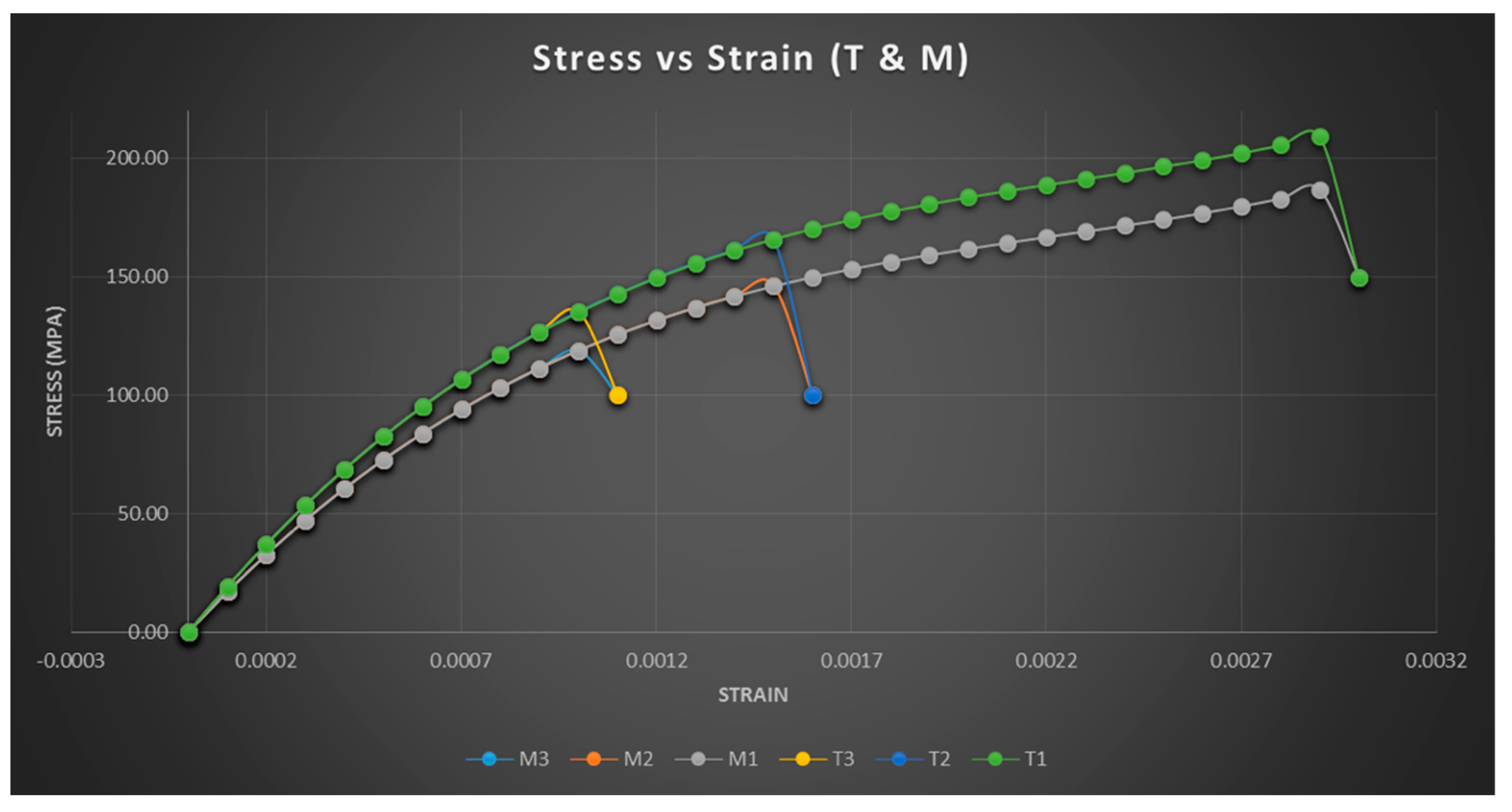
3.3.2. TDGLC + TG at T and M

In this test, for different locations of the joint and different specimen lengths, T1–T3 and M1–M3 are tested. A stress–strain curve of TDGCL + TG is shown at different locations at the top (T) and middle (M). The T location is slightly different from M. The test results are shown in Figure 11 with the following details:
3.
Test results (stress, strain) are in descending order: T1 (209.29, 0.0029), T2 (166.04, 0.0015), and T3 (3.84, 0.0010) are the points.
4.
Test results (stress, strain) are in descending order: M1 (186.84, 0.0029), M2 (146.45, 0. 0015), and M3 (118.94, 0.0010) are the points.

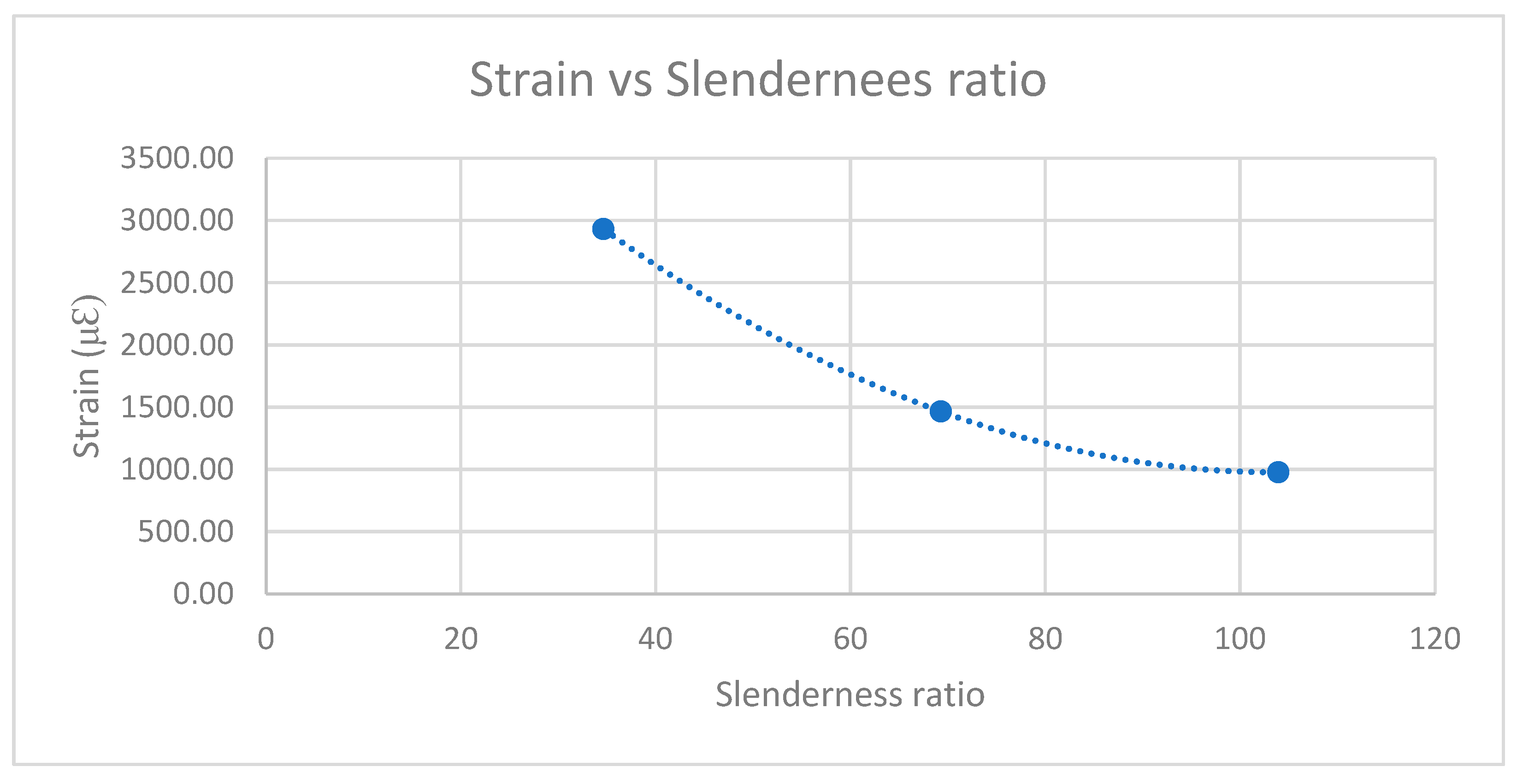
3.4. Strain–Slenderness Ratio Analysis

Regarding the strain–slenderness ratio of TDGLC + TG, Equation (6) can be used to express the strain. The regression model was tested to determine the relationship between the strain and slenderness. The results are shown in Equation (6) and Figure 12.
ε l = 0.4072   λ 2 84.63   λ + 5374.6
where εl is the maximum strain at mid height; λ is the slenderness ratio.
The results of the TDGLC + TG tests are summarized as shown in Table 4:
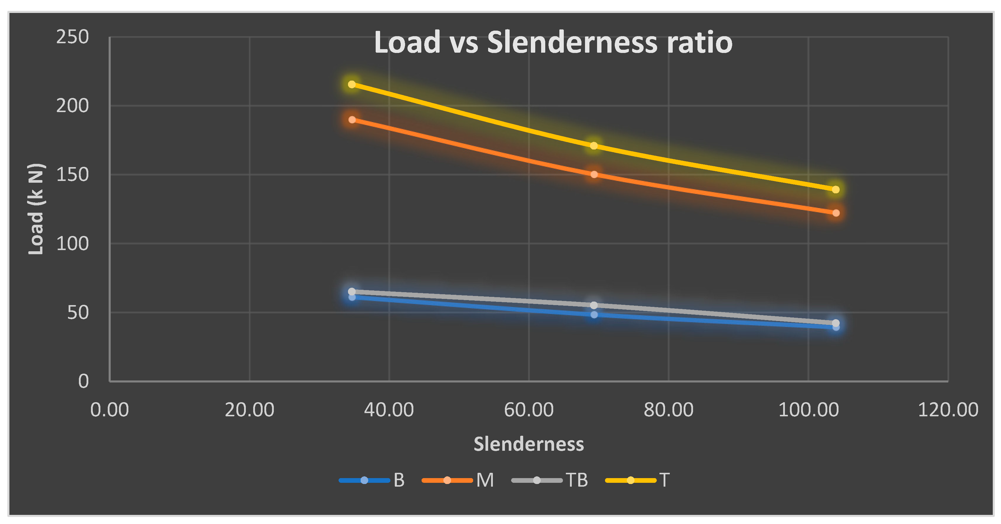
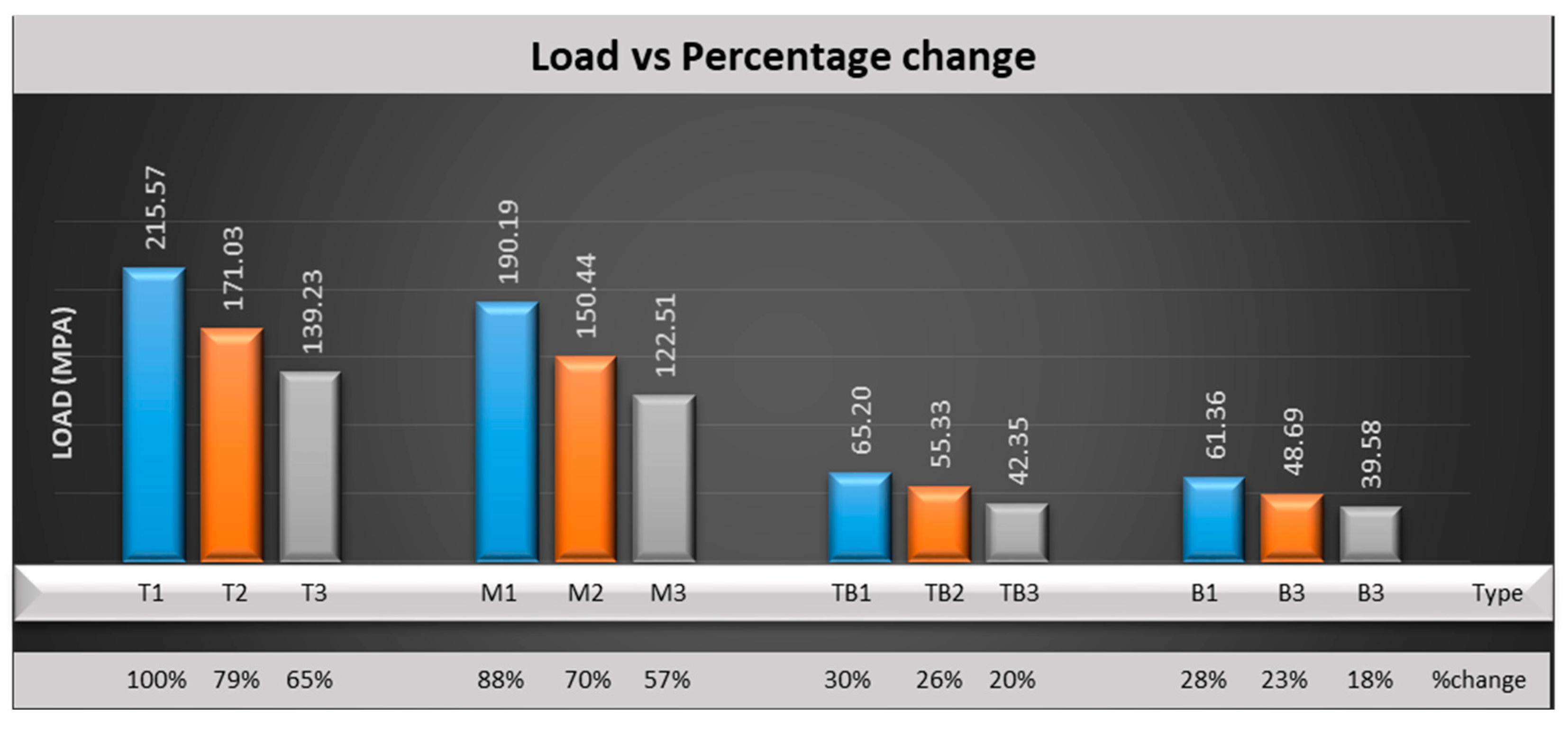
  • TDGLC + TG with the top connection type 4L01 T-4L03 T can withstand maximum loads ranging from 139.23 to 215.57 kN with a slenderness ratio of 34.6–103.92.
  • TDGLC + TG with the middle connection type 4L01 M-4L03 M can bear a maximum load of between 125.5 and 190.19 at a slenderness ratio of 34.6 to 100.38.
  • TDGLC + TG with the top-bottom connection type 4L01 TB and 4L03 TB can withstand high loads between 42.35 and 65.20 kN at a slenderness ratio of 42.35 to 65.20.
  • TDGLC + TG type 4L01 B-4L03 B can withstand loads ranging from 39.58 to 61.36 kN while maintaining a slenderness ratio of 34.64 to 102.92.
Load capacity depends on the column length. Short columns can carry more load than long columns, and the connection area affects the load as follows: The top connection can resist load better than the connection at the bottom.
Table 4. Test results.
SpecimensLength (mm)StrainSlenderness RatioUltimate Capacity (kN)
4L03 B30000.0010103.9239.58
4L02 B20000.001569.2848.69
4L01 B10000.002934.6461.36
4L03 TB30000.0010103.9242.35
4L02 TB20000.001569.2855.33
4L01TB10000.002934.6465.20
4L03 M30000.0010103.92122.51
4L02 M20000.001569.28150.44
4L01 M10000.002934.64190.19
4L03 T30000.0010103.92139.23
4L02 T20000.001569.28171.03
4L01 T10000.002934.64215.57

4. Discussion

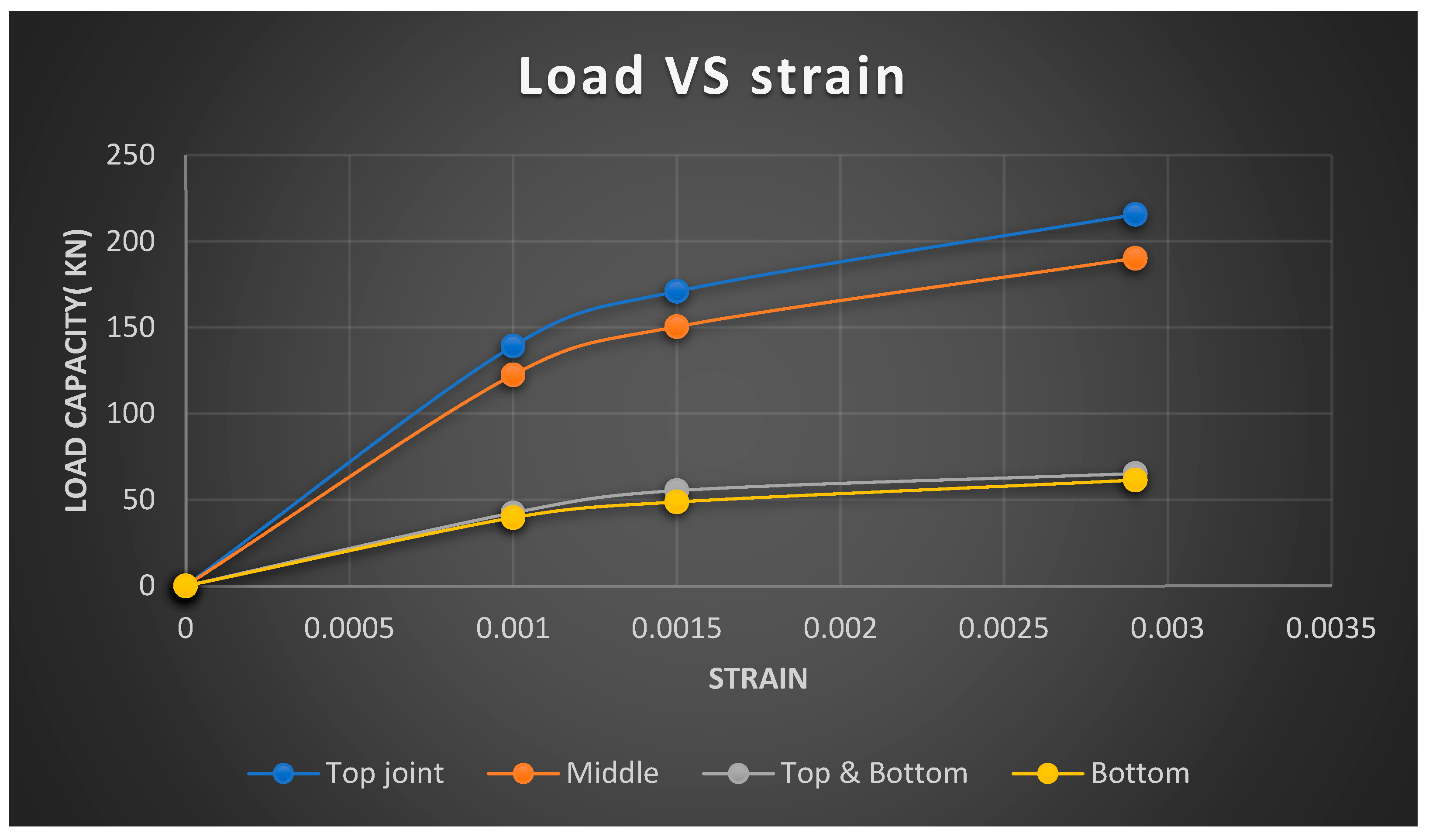
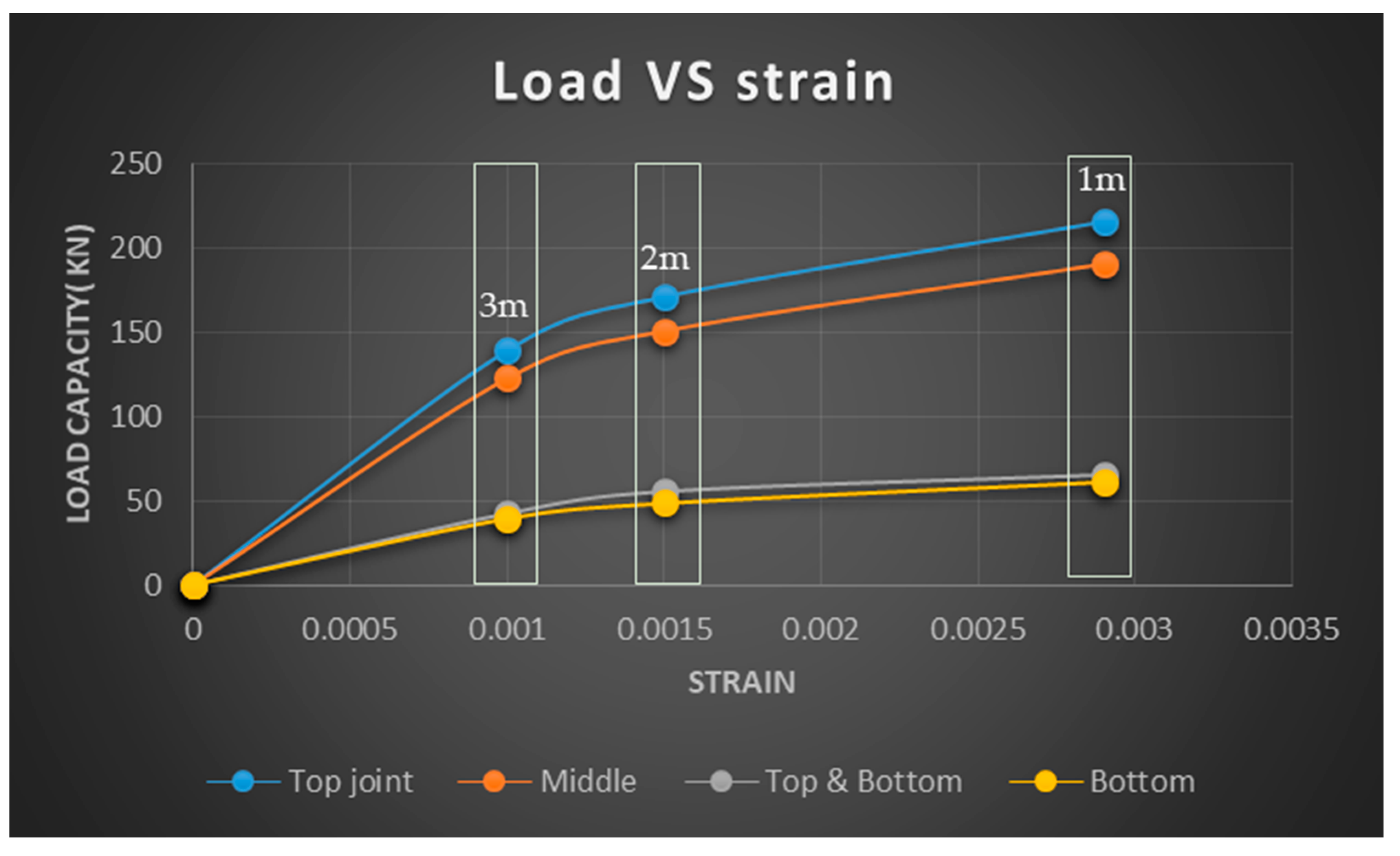
4.1. Load vs. Strain Comparison

A comparison of the capacity load of TDG columns 1 m, 2 m, and 3 m in length with different joint locations, all with the tongue and groove joint, is shown in Figure 13. The results show that the top joint can resist the highest load compared to other joint locations, and the bottom joint can resist the lowest capacity. As the load increased, the strain increased.
Figure 14 shows the results of the TDG laminated column of different length in the square frame shown in three groups: The dot with 3 m length has an approximate strain of 0.001; dot group 2 with 2 m length has an approximate strain of 0.0015; and the last dot group 1 m in length has an approximate strain of 0.003. From the test, one can observe that joints in different locations, such as T, M, TB, and B, with the same length obtained the same strain but different load capacities.

4.2. Slenderness vs. Load

Regarding the comparison between load and the slenderness ratio of TDGLC + TG with different joint locations, Figure 15 shows that the capacity increased when the slenderness decreased.

5. Summary and Conclusions

5.1. Load vs. Slenderness Ratio

Comparison of the load and the slenderness ratio of TDGLC + TG with the TDGLC without this joint is shown in Figure 16.

5.2. Stress vs. Strain

The relationship between stress and strain of TDGLC + TG can be summarized as follows: The strain of the specimens at different lengths differ in all connection areas. The results from the test can be divided into three parts: 1 m length, 0.0029; 2 m length, 0.0015; and 3 m length, 0.0010. The strain value depended on the length deformations. The stress load was affected by the connection area as shown in Figure 17.
Regarding the comparison of the loading of test specimens, to analyze the results from the maximum load, we accounted for 100% and decreased from there to compare the load descending by percent of the baseline. Figure 18 shows the specimen types 4L01–4L03.
Figure 19 shows the location of the joint with length of the specimens for T1–T3, M1–M3, TB1–TB3, and B1–B3.
The load can be classified according to the connection area as follows: At the top, specimen 4L01 T–4L03 T can resist loads ranging from 100–65 percent. For the middle specimen 4L01 M–4L03 M, the loading is between 88 and 57 percent. For the top-bottom 4L01 TB–4L03 TB, the load is between 30 and 20 percent. For 4L01 B–4L03 B, the load is between 28 and 18 percent. As shown in Figure 20.
This paper tested only the tongue and groove (TG) joint and only specimens with a cross-section of 100 mm. Further research can test different cross-sections to determine the load that affects different cross-sections and can compare and reference every cross-section of TDGLC.

Author Contributions

Conceptualization, C.T. and S.T.; methodology, S.R.T.; software, C.T. and C.P.; formal analysis, B.H. and C.T.; investigation, K.K.; resources, K.K.; writing—original draft preparation, C.T.; writing—review and editing, W.K.; supervision C.T. All authors have read and agreed to the published version of the manuscript.

Funding

This research received no external funding.

Institutional Review Board Statement

Not applicable.

Informed Consent Statement

Not applicable.

Data Availability Statement

Not applicable.

Conflicts of Interest

The authors declare no conflict of interest.

Abbreviations

Note: Abbreviation definition for this paper the detail are as follows.
TDGThai Dendrocalamus Giganteus
TDGLC + TGThai Dendrocalamus Giganteus bamboo laminated column with Tongue and Groove joint

References

  1. Amada, S.; Ichikawa, Y.; Munekata, T.; Nagase, Y.; Shimizu, H. Fiber texture and mechanical graded structure of bamboo. J. Compos. Part B Eng. 1997, 28, 13–20. [Google Scholar] [CrossRef]
  2. Díaz, G. Influencia de la Densidad Aparente de Fibras sobre la Resistencia a Esfuerzos de Compresión, Tensión y Flexión de la Guadua (Influence of the Apparent Density of Fibers on the Compressive Strength, Tension and Bending of Guadua). Master’s Thesis, Universidad Industrial de Santander, Bucaramanga, Colombia, 2011. [Google Scholar]
  3. Yeh, M.-C.; Lin, Y.-L. Finger joint performance of structural laminated bamboo member. J. Wood Sci. 2011, 58, 120–127. [Google Scholar] [CrossRef]
  4. Li, H.; Zhang, Q.; Huang, D.; Deeks, A.J. Compressive performance of laminated bamboo. J. Compos. Part B Eng. 2013, 54, 319–328. [Google Scholar] [CrossRef]
  5. López, L.F. Estudio Exploratorio del Potencial Estructural de Laminados de Guadua (Exploratory Study of the Glued Laminated Bamboo Guadua Angustifolia as a Structural Material. Master’s Thesis, Universidad de Los Andes, Bogotá, Colombia, 2008. [Google Scholar]
  6. De Flander, K. The Role of Bamboo in Global Modernity: From Traditional to Innovative Construction Material. Master’s Thesis, Wageningen University, Wageningen, The Netherlands, 2005. [Google Scholar]
  7. Karthik, S.; Rao, P.R.M.; Awoyera, P. Strength properties of bamboo and steel reinforced concrete containing manufactured sand and mineral admixtures. J. King Saud Univ.-Eng. Sci. 2017, 29, 400–406. [Google Scholar]
  8. Sharma, B.; Gatóo, A.; Ramage, M.H. Effect of processing methods on the mechanical properties of engineered bamboo. Constr. Build. Mater. 2015, 83, 95–101. [Google Scholar] [CrossRef]
  9. Li, X. Research on Mechanics and Failure Properties of Moso Bamboo. Master’s Thesis, Chinese Academy of Forestry, Beijing, China, 2009. [Google Scholar]
  10. Tang, G.; Yin, L.; Li, Z.; Li, Y.; You, L. Structural behaviors of bolted connections using laminated bamboo and steel plates. Structures 2019, 20, 324–339. [Google Scholar] [CrossRef]
  11. Mali, P.R.; Datta, D. Experimental evaluation of bamboo reinforced concrete beams. J. Build. Eng. 2020, 28, 101071. [Google Scholar] [CrossRef]
  12. Sharma, B.; van der Vegte, A. Engineered bamboo for structural applications. In Nonconventional and Vernacular Construction Materials; Elsevier: Amsterdam, The Netherlands, 2020; pp. 597–623. [Google Scholar]
  13. Thammapornram, C. The Innovation of Dendrocalamus Giganteus Bamboo Beam. Ph.D. Thesis, Faculty of Engineering Law and Inspection, Ramkhamhaeng University, Bangkok, Thailand, 2018. [Google Scholar]
  14. Thamapornram, C.; Kongsong; Buranakarn, V. Thai Dendrocalamus Giganteus. J. Science, Technology, and Architecture, ESTCON Thailand, 2018; pp.60–70. Available online: https://estcon.utp.edu.my/ (accessed on 2 September 2022).
  15. Thammapornram, C.; Kongsong, W.; Buranakarn, V. Effecting factors of mechanical properties of thai dendrocalamus giganteus bamboo. Int. J. Civ. Eng. Technol. 2018, 9, 1457–1467. [Google Scholar]
  16. Songkarn, K. The Innovation of Dendrocalamus Giganteus Bamboo Column. Ph.D. Thesis, Faculty of Engineering Law and Inspection, Ramkhamhaeng University, Bangkok, Thailand, 2019. [Google Scholar]
  17. Muhammad, F.; Haris, M.; Khan, W.; Zaman, S. Bamboo as a construction material: Prospects and challenges. Adv. Sci. Technol. Res. J. 2022, 16, 165–175. [Google Scholar]
  18. Kumar, G.; Ashish, D.K. Review on feasibility of bamboo in modern construction. J. Civ. Eng. 2015, 2, 66–70. [Google Scholar]
  19. Habibi, S. Design concepts for the integration of bamboo in contemporary vernacular architecture. Archit. Eng. Des. Manag. 2019, 15, 475–489. [Google Scholar]
  20. Liese, W. Research on bamboo. Wood Science and Figure 7. Load-displacement relations in split tensile tests for FRBC and PCC. Adv. Sci. Technol. Res. J. 2022, 16, 165–175. [Google Scholar]
  21. Sayan, K. The Innovation of Thai Dendrocalamus Giganteus Bamboo Joints According to Building Control Act and Safety Standard. Ph.D. Thesis, Faculty of Engineering Law and Inspection, Ramkhamhaeng University, Bangkok, Thailand, 2019. [Google Scholar]
  22. Kongsricharoen, S.; Kongsong, W.; Tuprakay, S.; Tuprakay, S.; Thammapornram, C. Analysis the shear strength of Thai Dendrocalamus Gigantues (TDG) lamented bamboo by the factor of glue and location of the strips. Int. J. Civ. Eng. Technol. 2019, 10, 253–262. [Google Scholar]
  23. Ashaari, Z.; Mamat, N. Traditional treatment of Malaysian bamboos: Resistance towards white rot fungus and durability in service. Pak. J. Biol. Sci. 2000, 3, 1453–1458. [Google Scholar]
  24. Kasim, J. Properties of Particleboard and Particle-filled Thermoplastic Composite from Bamboo (Gigantochloa Scortecchinii). Master’s Thesis, Universiti Putra Malaysia, Selangor, Malaysia, 1999. [Google Scholar]
  25. Parameswaran, N.; Liese, W. On the fine structure of bamboo fibres. Wood Sci. Technol. 1976, 10, 231–246. [Google Scholar] [CrossRef]
  26. Sharma, Y. Editor bamboos in the Asia Pacific Region. Bamboo research in Asia. In Proceedings of the Bamboo in the Asia Pacific Region Workshop, Singapore, 28–30 May 1980; IDRC: Ottawa, ON, Canada, 1980. [Google Scholar]
  27. Thammapornram, C. The Innovation of Dendrocalamus Giganteus Bamboo Column. Available online: https://megabamtech1212.com/bamboo-column/ (accessed on 10 October 2022).
  28. Rachata, P.; Waranon, K.; Chaleeporn, T. Analysis of physical properties Thai Dendrocalamus Gigantues (TDG) bamboo case study strips making. Int. J. Adv. Res. Eng. Technol. 2021, 11, 816–828. [Google Scholar]
  29. Krittapat, K.; Waranon, K.; Chaleeporn, T. Analysis of physical properties The Dendrocalamus Gigantues (TDG) bamboo case study the factor of differnt location Node and Internode. Int. J. Manag. 2022, 11, 308–318. [Google Scholar]
  30. Rachata, P.; Waranon, K.; Chaleeporn, T. Analysis of emission factor in Thailand for vechicle transportation that affects the carbon foorprint in production process of Thai Dendrocalamus Gigantues (TDG) laminated. Int. J. Adv. Res. Eng. Technol. 2021, 12, 816–828. [Google Scholar]
  31. ASTM D143-09; Standard Test Method for Small Clear Specimens of Timber. ASTM international: West Conshohocken, PA, USA, 2009.
  32. DPT 1221-51; Standards Test of Wood. The Bureau of Building Inspection and Control Department of Public Works and Town & Country Planning: Bangkok, Thailand, 2022.
  33. DPT 1225-51; Standards Test Method for Tensile Test of Wood. The Bureau of Building Inspection and Control Department of Public Works and Town & Country Planning: Bangkok, Thailand, 2022.
  34. DPT 1224-51; Standards Test for Bending Test of Wood. The Bureau of Building Inspection and Control Department of Public Works and Town & Country Planning: Bangkok, Thailand, 2022.
  35. DPT 1222-51; Standards Test for Compressive Strength of Wood. The Bureau of Building Inspection and Control Department of Public Works and Town & Country Planning: Bangkok, Thailand, 2022.
  36. Krittapat, K.; Waranon, K.; Chaleeporn, T. Analysis of thai Dendrocalamus Gigantues bamboo (TDG) strip method of production a different method. Int. J. Adv. Res. Eng. Technol. 2021, 12, 75–87. [Google Scholar]
  37. Zhang, J.P.; Wang, S.S.; Gong, S.; Zuo, Q.S.; Hu, H.Y. Thermo-mechnical coupling analysis of the orthropic structures by using element –free Galerkin method. Eng. Anal. Bounday Elem. 2019, 101, 198–213. [Google Scholar] [CrossRef]
  38. Kabir, H.; Aghdam, M.M. A generalized 2D Bezier based solution for stress analysis of notch epoxy resin plates reinforced with graphene nanoplatets. Thin-Walled Struct. 2021, 169, 108484. [Google Scholar] [CrossRef]
Figure 1. The TDG column cut to the groove and tongue.
Designs 06 00107 g001
Figure 2. Column details: 4-side plan and xyz coordination.
Designs 06 00107 g002
Figure 3. The location of connection.
Designs 06 00107 g003
Figure 4. Detail of the test specimens.
Designs 06 00107 g004
Figure 5. Detail failure at tongue and groove.
Designs 06 00107 g005
Figure 6. Splitting mode.
Designs 06 00107 g006
Figure 7. Splitting + buckling mode.
Designs 06 00107 g007
Figure 8. Splitting mode.
Designs 06 00107 g008
Figure 9. Load capacity vs. slenderness ratio.
Designs 06 00107 g009
Figure 10. Comparison of the stress–strain curve for types B and TB.
Designs 06 00107 g010
Figure 11. Comparison of the stress–strain curve for types T and M.
Designs 06 00107 g011
Figure 12. Maximum strain vs. slenderness ratio.
Designs 06 00107 g012
Figure 13. Comparison of capacity load of TDGLC + TG.
Designs 06 00107 g013
Figure 14. Comparison of capacity load of TDGLC + TG.
Designs 06 00107 g014
Figure 15. Comparison of capacity load of TDGLC + TG.
Designs 06 00107 g015
Figure 16. Comparison of capacity load of TDGLC + TG vs. TDGLC without Joint.
Designs 06 00107 g016
Figure 17. Stress vs. strain.
Designs 06 00107 g017
Figure 18. Analysis of % load.
Designs 06 00107 g018
Figure 19. Analysis of % load.
Designs 06 00107 g019
Figure 20. A comparison of TDGLC +TG (WJ) and without joint (WOJ).
Designs 06 00107 g020
Table 1. Mechanical performance of TDG laminated bamboo (standard size).
PropertyMaximumMinimumAverage
Compressive strength parallel to grain fv (MPa)69.6520.8249.27
Modulus of elasticity in compression EC (MPa)9518.595365.747721.04
Table 2. Specimen types.
TypeLocation of JointCodeLength (m)Number
4L01 BbottomB16
4L02 BbottomB26
4L03 BbottomB36
4L01 TBTop and bottomTB16
4L02 TBTop and bottomTB26
4L01 TBTop and bottomTB36
4L01 MmiddleM16
4L02 MmiddleM26
4L03 MmiddleM36
4L01 TtopT16
4L02 TtopT26
4L03 TtopT36
Table 3. Failure Mode.
SpecimensModeType of Failure
4L01T1, 2Splitting, Adhesive failure (ADH)
4L02T1, 2Splitting, Adhesive failure (ADH)
4L03T1, 2Splitting, Adhesive failure (ADH)
4L01M1, 2, 3Splitting, Adhesive failure (ADH), Buckling
4L02M1, 2, 3Splitting, Adhesive failure (ADH), Buckling
4L03M1, 2, 3Splitting, Adhesive failure (ADH), Buckling
4L01TB4Splitting, Adhesive failure (ADH)
4L02TB4Splitting, Adhesive failure (ADH)
4L03TB4Splitting, Adhesive failure (ADH)
4L01B1, 2Splitting, Adhesive failure (ADH)
4L02B1, 2Splitting, Adhesive failure (ADH)
4L03B1, 2Splitting, Adhesive failure (ADH)
Publisher’s Note: MDPI stays neutral with regard to jurisdictional claims in published maps and institutional affiliations.

