Abstract
Thickness checking is one of the quality control procedures in the brake pad industry. This research aims to address the issue of the time effectiveness of the thickness checking by turning the technique into an automatic process, from specimen preparation to data recordings; the technical aspects, the geometric design, and the structure analysis are critical elements of the industrial machinery. However, economic analysis is considered when it becomes an investment by a company with long-term use expectations. Thus, this research provides structural analysis, time checking estimation, and simple investment feasibility studies on break-even points and a simple payback period to ensure that the new design can improve testing performance. Monte Carlo simulation offers the calculation of investment feasibility with the three possibilities of pessimistic, optimistic, and realistic results in achieving a break-even point (BEP) and a simple payback period.
1. Introduction
Disc brakes are one of the most fundamental safety components in ground transportation. They slow down or stop the wheel’s rotation by forcing frictional materials against the disc rotor to apply a braking force. The process of friction and wear between the brake pads and the disc rotor affects the braking performance and driving comfort. This process often causes a phenomenon of an unwanted and annoying sound called brake squealing that makes the driver uncomfortable [1,2]. The brake squeal issue is typically irritating to the consumers who believe it is an indication of a defective brake; yet, the brake is functioning well, and they are not required to replace the brake pads but must continuously face the high-pitched squealing noise. Since the invention of automotive brake systems, brake squeal has been one of the most challenging problems and one of the most important rating items in the initial quality control for automobiles, and both brake and automotive manufacturers have made efforts to address the issue [3,4,5]. The automotive industry faces significant technical and financial issues related to the noise and vibration produced by passenger car braking systems. In fact, as highlighted by Abendroth and Wernitz [6], several producers of brake pad materials devote up to 50% of their technical resources to harshness, vibration, and noise problems.
Several previous studies have reported that the brake pad dimensions influence the disc brake squealing. The stiffness of the brake pad and the dimensions from the frictional contact surface to the rotational pad center are affected by the brake pad’s thickness, which in turn affects how loudly the brake squeals [7]. It was shown through a squeal test utilizing a pad of varying thickness that the squeal frequency increased when the pad became thinner. The results showed that the pad stiffness increased as the pad thickness decreased; in other words, the brake pad will squeal when the pad becomes stiffer [8]. Therefore, in order to avoid the problems that have been discussed, it is possible to make sure that the size of the manufactured brake pad complies with the design and standards. Thus, it would be ideal to use better measurement instruments during production.
Dimensional measurement is a standard procedure in brake pad manufacture. However, few publications show how to make it more advanced and how there can be more testing on a production line. Generally, measuring the dimensions of a brake pad is a non-destructive method that does not cause damage to the material [9]. A novel thickness and dimension test method that complies with the production demands needs to be developed. For example, a brake pad company in Indonesia still uses the manual method of using a caliper to measure the thickness and dimensions of the brake pads. The previous manual checking method has problems with time efficiency, bottlenecks, cycle times, and human error in testing and recording the test results on a computer. It needs to be mentioned that it is mandatory to test about 10% of their mass production, and these products have to be inspected through quality control. This phenomenon indicates that it is necessary to solve the problem with a new method that can automatically and precisely inspect multiple brake pads in one cycle.
Several previous studies have reported on their work regarding innovations in designing automatic brake pad thickness checks to prevent brake squeal [10,11]. Those two studies used the ultrasonic method, which can also be used to obtain brake lining thickness data. The use of ultrasonic sound is not just to measure the thickness but also to determine the mechanical properties of the materials, due to the fundamental connection between the ultrasonic velocity and the materials’ elastic constants [12]. However, the studies that use ultrasound to automate the brake pad thickness measurement have several issues, including coupling ultrasound to the sample, component scanning, and automation of the time-of-flight (ToF) measurement [10]. The ultrasound coupling into and out of the brake pad is the main practical issue of a fully automated measurement system. As the frequency of ultrasonic sound is high, the ultrasound is weakened by air, and significant signal loss happens due to the strong acoustic impedance discontinuity between the brake pad and the air. Moreover, the design of the ultrasonic system for automated measurement can only accommodate one brake pad in a cycle test, and it is not a fully automatic machine as the data need to be uploaded manually on the record [11].
Based on the findings of those two methods, an automatic tool that helps the process of testing the thickness of the brake pad in the quality control line needs to be made. Hence, the checking process will be faster and able to meet the production demand. Quality control in the brake pad industry not only ensures good quality products that reach the customers but also increases the company’s profit [13]. The development of innovative products needs to be complemented by analyzing the investment feasibility. Therefore, the technical and economic justifications are born for a business or investment to be made. Another function of this analysis is to be an effort to prevent losses if the tool is predicted not to provide significant optimization of the previous method. There are several ways to determine whether a business or investment is feasible [14,15]. The break-even point and the payback period are two of the most popular and will be discussed in this paper.
It was found that there are not many studies on the development of automatic brake pad checking equipment that have been published in the public domain. The main objective of this paper is to improve the performance of brake pad quality control of its thickness by performing an automatic mechanism. This paper also addresses the investment feasibility that is necessary to carry out in the production planning. To this end, a brief introduction to the importance of brake pad thickness checking is reviewed, and the currently available methods of thickness checking are described. After that, some general equations to calculate structural strength and investment feasibility are provided. Later, a prototype design with finite element settings is needed to calculate the structural strength and investment feasibility; in the final section of this paper, structural strength simulation, time estimation of a one-cycle test, and investment feasibility are carried out. A discussion comparing the method in this study and other thickness checking methods closes the paper.
2. General Equations
2.1. Von Mises Stress
The von Mises failure theory is a failure theory applied to ductile materials. This theory predicts failure due to yielding, which results in permanent plastic deformation [16]. The von Mises theory is also known as the maximum energy distortion theory. This theory states that failure or yielding in a component structure when the value of the shear strain energy per unit volume reaches the energy distortion limit per unit volume causes failure, as determined by a simple uniaxial stress test. The von Mises criterion can also be defined in terms of stress components in any Cartesian coordinate system, as stated in Equation (1).
2.2. Deflection
Deflection occurs when loads and forces are applied to a structure. This phenomenon results in the structure’s movement from its initial position [17]. Several factors affect the deflection of a frame, such as the material of the frame, the applied force, the moment of inertia of the section, and the distance from the support.
Equation (2) is a general beam deflection equation affected by a transverse load that can be derived for other structural design purposes. As EI is flexural rigidity and the value may change along the beam, the function x must be determined first.
2.3. Factor of Safety
An applied maximum load on machine components or structures under normal conditions must be smaller than the ultimate load in order to work safely [18]. In this context, the smaller maximum load is the allowable load, as stated in Equation (3).
There are several considerations in choosing the value of the safety factor, such as the type of material, the type of manufacturing process, the type of load, and the shape of the component itself. Choosing a small safety factor value can increase the probability of component failure. On the other hand, selecting a more extensive safety factor can cause uneconomic components and poor functioning.
2.4. Investment Feasibility Study
An investment feasibility study of a business is a process of discussing the basic concepts related to the decision and selection of business projects with economic and social benefits. Feasibility means that a business can provide the desired financial and non-financial benefits for a company, the investors, the creditors, the government, and the community [19].
2.4.1. Break-Even Point
A break-even point (BEP) is a condition in which the business does not make a net profit or a loss. Net profit will be obtained if the sales or production volume is above the BEP, while a net loss will occur if the sales or production volume is below the BEP. The BEP analyzes the projected volume of units that must be produced or sold and determines how much income must be earned to break even [20].
The two most common types of BEPs in Equations (4) and (5) are break-even units, which analyze the minimum units that must be sold or produced, and break-even revenues, which analyze the minimum revenue that must be collected on the product sold.
2.4.2. Simple Payback Period
The payback period can be defined as the length of time an investment project requires to get its investment costs back with the cash generated by the investment project [20]. The basic premise of the payback period is that the sooner the investment cost is recovered, the better the type of investment. Investing in projects with faster returns can give companies more flexibility because funds for other projects can be organized easily if the company is unsure about the cash flow projections. The payback period can be calculated by Equation (6) below.
3. Material and Methodology
3.1. Geometrical Model
The design process starts by analyzing the market or potential user needs, specifications, and design feasibility. Market research has an essential role in discovering the highly available parts in the market; so, this design strongly promotes DFMA in the research process. The design diagrams consist of 3D designs, which visualize the profile and how the machine will perform the jobs. All these works are performed on Autodesk Fusion360 Student Version software (Autodesk, San Rafael, CA, USA). One of the first stages of the design procedures is knowing the size of the main moving component, such as a linear drive. Therefore, the support frame will follow the needs of those parts.
The three aspects below can optimize the quality control process in checking the thickness of the brake pads:
- The inspection activity and data input of the checking results can be performed automatically; so, the operator only puts the brake pads on the testing jig.
- The future equipment should perform multiple brake pad tests under one cycle test.
- The equipment design should be ergonomic and adjustable to the operator’s posture.
The sensor used in the design is a limit switch, one of the types of contact sensors. This sensor has the advantage of a lower price but still also has high accuracy in use. One of this tool’s design goals is to test several brake pad specimens in one cycle; so, to achieve this a jig is needed to support several specimens during quality control. The design of this jig is broadly varying, depending on the specimen’s size. Aside from those two features, the design of the automatic brake pad thickness checking machine is made more ergonomic by adding height-adjustable legs and a retractable brake pad jig to allow the tool to adapt to the operator’s posture.
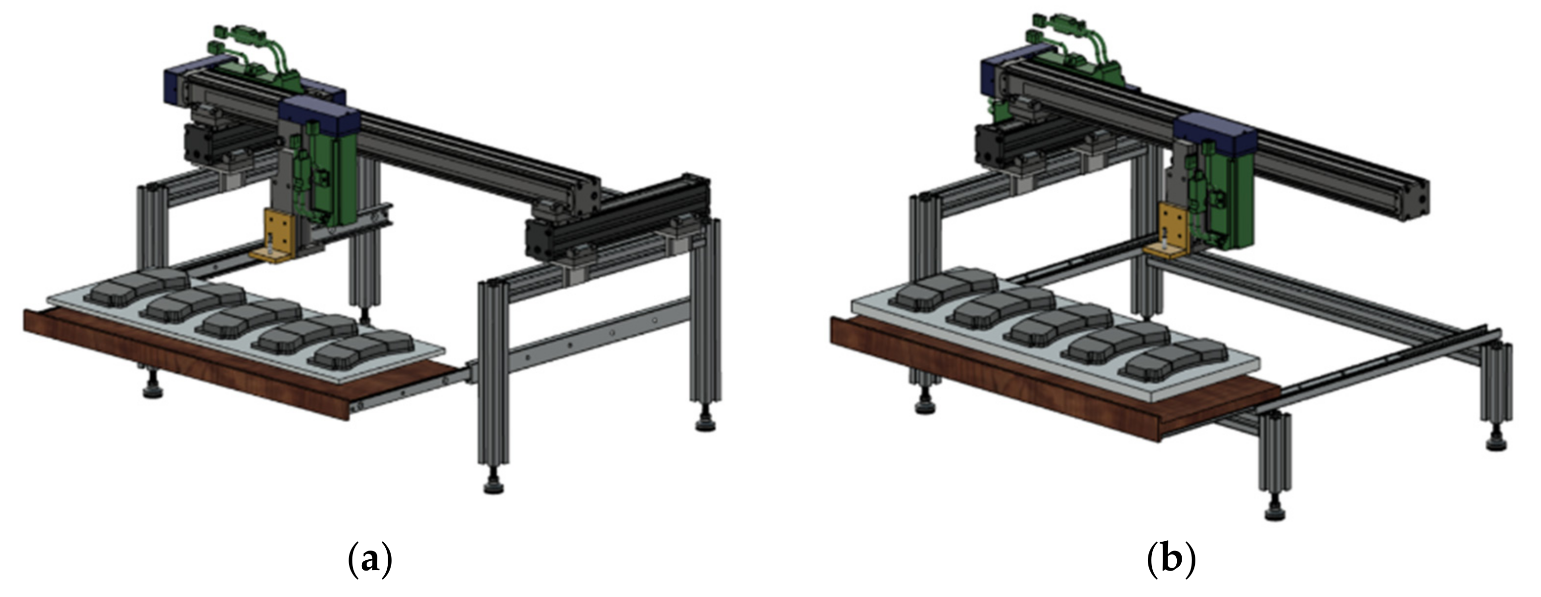
The first type of design is the model with the overhead crane system Figure 1a, which has the advantage of good stability at both ends of the horizontal frame but has the disadvantage of a higher price than the cantilever crane system because it requires additional driving support devices. The second model (Figure 1b) works with a cantilever crane mechanism, which is more lightweight than the first design. However, this mechanism is no more stable than the overhead crane system with two supports on the y-axis drive.
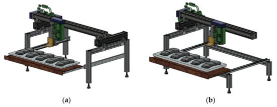
Figure 1.
Product Design of Automatic Brake Pad Thickness Checking Machines: (a) Overhead Crane Type; (b) Cantilever Crane Type.
One of the many benefits of aluminum frames is their adaptability to various shapes and sizes [21]. In addition, aluminum has excellent characteristics, such as its mass–strength ratio, corrosion resistance, and temperature resistance [18]. As shown in Figure 2, this research applies four types of cross-sectional variations of the T-Slot frame shapes because of their strength and flexibility. This frame was chosen as it is readily available on the market, making the machine in this study easy to manufacture. One of these aluminum frame material providers is Misumi Indonesia, which provides various types of aluminum frames as needed.

Figure 2.
Geometrical Model of Aluminum Frame Extrusions: (a) Standard; (b) Economy; (c) Lightweight; (d) High-Rigidity.
3.2. Previous Study on T-Slot Structural FE Simulation
A validation procedure for finite element simulation is required to distinguish the accuracy of the results by comparing the methodologies of the past and present studies. Thus, this procedure can guarantee that the outcomes are substantially accurate and accountable. There are several ways to complete the validation process, including utilizing an analytical method with an existing equation, comparing with previously established experimental results, or comparing the results of numerical method simulations of similar studies [22,23].
Previous research on the structural load of an automatic hardness-checking machine serves as the validation procedure [24]. The design development process uses a T-Slot aluminum profile sized 45 × 45 (mm) as its structural frame, with two main sections, the upper and lower frames. Therefore, it has total dimensions of 1020 mm in length, 515 mm in width, and 580 mm in height.
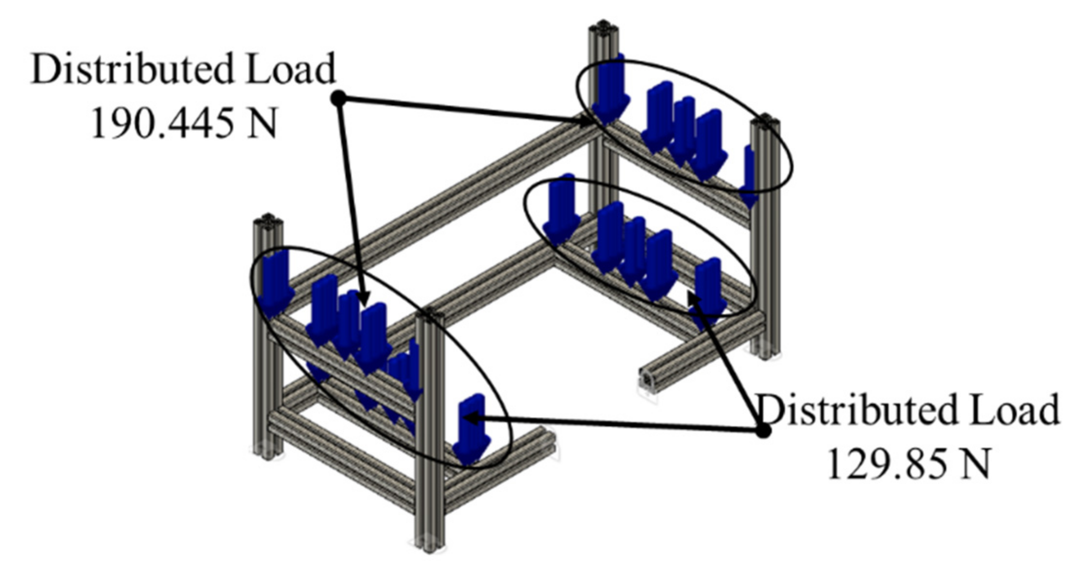
As shown in Figure 3, the distributed loads are given on the structural frame on which the loads are supported, with totals of 380.89 N on the upper frame and 190.445 N on the lower frame. Every two loads are divided into two equal loads; therefore, the upper load will support 190.445 N on the right and left sides. Similarly, the lower frame will support 129.85 N on each side. The material used in the development is aluminum Al6060, and its mechanical properties can be seen in Table 1 below.
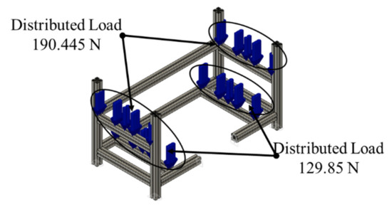
Figure 3.
Load Model Distribution of Prior Study as a Validation Procedure.

Table 1.
Mechanical Properties of Aluminum Al6060.
The current simulation study replicates the previous finite element simulation setup; yet, the setup for the mesh sizes is configurable. However, other elements, such as the parabolic element order, the 60° maximum turn angle on curves, the 1.4 maximum adjacent mesh size ratio, the 10 maximum aspect ratios, and the 20% minimum element size, are fixed as a setup configuration on FEM. The results are shown in Table 2 by varying the mesh size as an independent variable from 5 mm to 60 mm with a 5 mm interval in each simulation case.

Table 2.
Validation Results of the Previous Study.
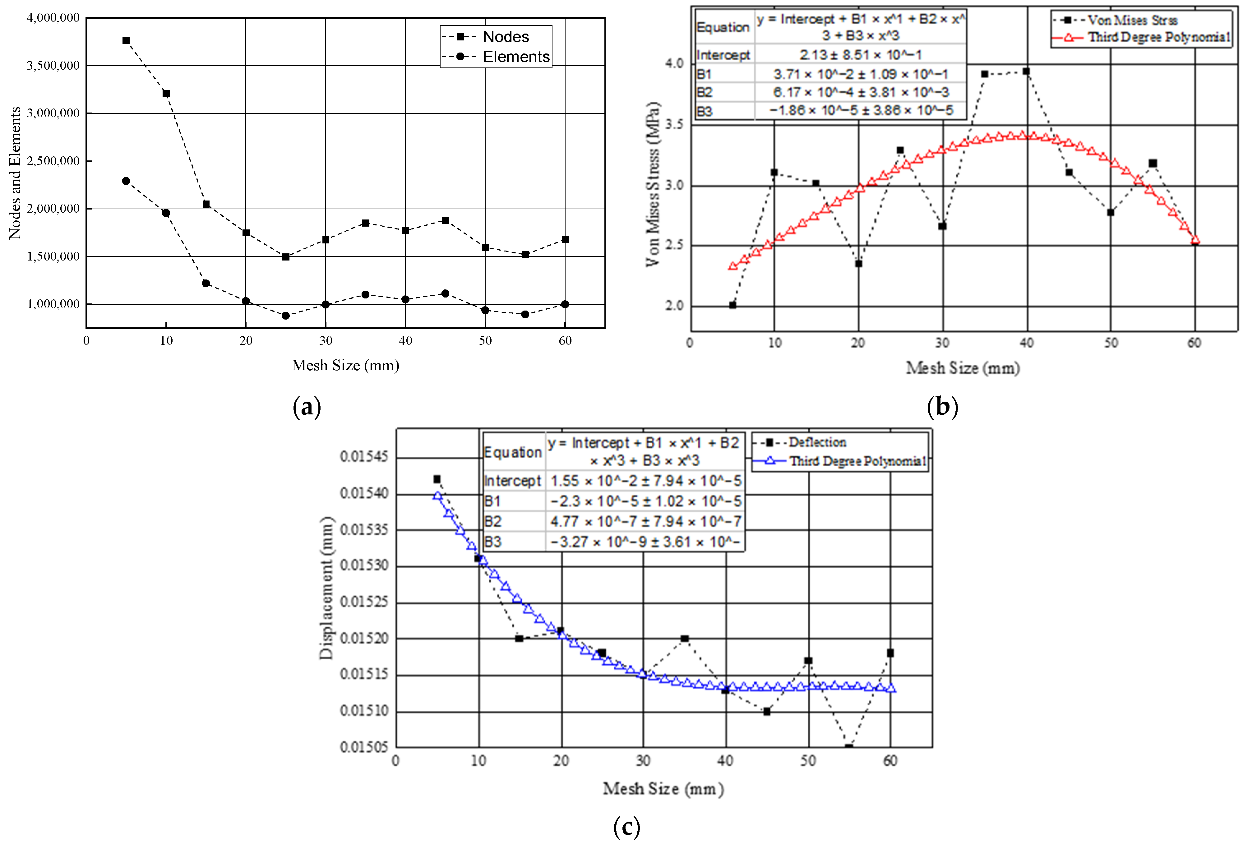
Table 2 above informs the result of the validation process by replicating the previous study setup and geometry. It provides the best results on the 30 mm mesh size by performing 12 variations of the simulation study; this was proved with the acquired 2.15% smallest von Mises stress ratio and the gain of 2.66 MPa. The displacement value obtained in this simulation is 15.15 × 10⁻³ mm with a 1.52% error ratio. The safety factor acquired in this process is remarkably similar to the reference, with a scored 15 and 0% in the ratio.
Figure 4a–c compares the graph lines of the total nodes, the total elements, the von Mises stress, and the displacement to the variance of the mesh sizes. From the three figures above, it can be concluded that the larger the mesh size, the smaller the number of nodes and elements, as well as the displacement. Meanwhile, the von Mises stress graph line tends to increase from the beginning and stops at around the 40 mm mesh size, followed by a sharp decline.
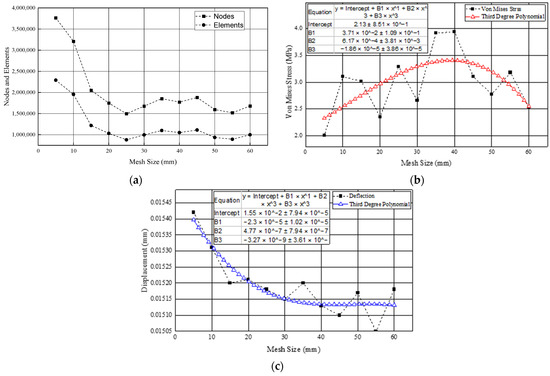
Figure 4.
Trend Line Comparison Results of Prior Study: (a) Mesh Size against Nodes and Elements; (b) Mesh Size against Von Mises Stress; (c) Mesh Size against Displacement.
The FEM simulation in Figure 5 shows that the locations with a critical stress reaction are the parts that directly support the payloads and the connection parts. Meanwhile, the locations in which the most significant deformations occurred are mainly those which directly support the payload. In a previous study, the maximum von Mises stress measured was 2.6 MPa, and the maximum displacement was 8.8 × 10⁻³ mm.

Figure 5.
Contour Structural Analysis of Prior Study: (a) Von Mises Stress Contour; (b) Displacement Contour.
3.3. Materials and FE Setting
Although there are four types of aluminum frame designs, only two material variants are used: aluminum A6N01S-T5 for the standard and lightweight frames and aluminum A6063-T5 for the economic and high-rigidity frames. As referred to in Table 3, the high-rigidity type has the largest sectional area of about 377 m2, and the smallest sectional area is figured out for the lightweight type of about 280 m2. Considering that the high-rigidity type has the largest sectional area among the other types, this material type is less strong than the lightweight type with the least sectional area. Otherwise, the standard type has similar mechanical properties to the lightweight type, but the economy type has similar mechanical properties to the high-rigidity type. The complete details of each mechanical property are shown in Table 4 below.

Table 3.
Cross-Sectional Area of Each Type of Aluminum Frames.

Table 4.
Mechanical Properties of Aluminum Frames.
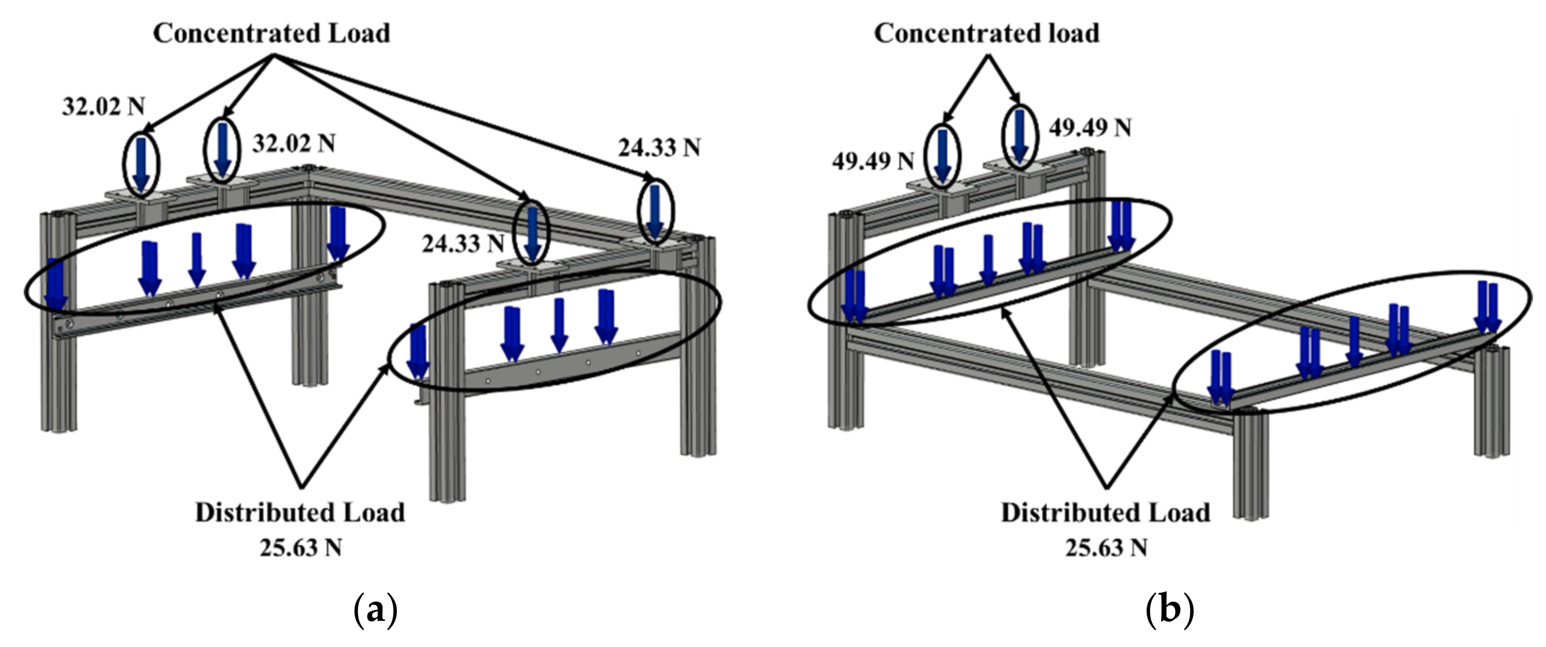
In this design, the FEM simulation is performed using Autodesk Fusion 360 with four fixed constraint locations on each leg frame to ensure that the object’s support does not move along all the axes (see Figure 6). Furthermore, this simulation uses a mesh size setting of 30 mm, a 60° maximum turn angle on the curves, a 1.4 maximum adjacent mesh size ratio, a 10 maximum aspect ratio, and a 20% minimum element size.
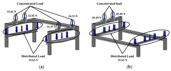
Figure 6.
Load Distributions of Automatic Brake Pad Thickness Checking Machine: (a) Overhead Crane; (b) Cantilever Crane Type.
The difference between the given load and that of the overhead and cantilever crane is that the total load value supported by the overhead crane frame is heavier because of an additional linear drive on the upper right frame in the design. However, both sides of the overhead crane support the longest linear drive, but the longest linear drive is supported independently by the cantilever crane design. This condition makes the upper left frame of the overhead crane support only 64.04 N and only 49.49 N for the cantilever crane. At the same time, a total of 48.66 N is loaded to the right upper frame of the overhead crane.
3.4. Monte Carlo Simulation
The calculation of the BEP and payback period using MCS will produce three main scenarios: the minimum, the maximum, and the average value of the predicted BEP or payback period. The Monte Carlo simulation process would be better if conducted with a spreadsheet-type software tool such as Microsoft Excel. This software is used to assist in generating random values and repeating the simulation with a series of iterations [14].
3.4.1. Assign the Variables and the Distributions
The fixed and variable costs are utilized in the BEP calculation, but the components of these prices may vary depending on the case of a particular type of investment or business. The calculated BEP value is the break-even number of units and the break-even revenues. Meanwhile, calculating a simple payback period only uses two main variables: investment costs and annual net cash flow. While obtaining the cash flow value can be conducted by looking for the factory’s total production capacity, in this case the reference is PT. Akebono; in a study conducted by Mohammad Fajar, it is known that the annual production capacity is 1,900,000 units of brake pads [25].
Assigning the distribution type from the variables depends on the type of data availability. If there are only two data, namely the estimated minimum and maximum prices, uniform distribution can be used. Nevertheless, if the estimated minimum, maximum, and mode prices that occur frequently exist, then a triangular distribution can be used to predict the BEP and the payback period.
3.4.2. Assign Random Number in the Calculation
To simulate the possible probability on a scale from 0 to 1, it is necessary to generate random numbers for the calculation process. Entering the formula = RAND() in Microsoft Excel generates random numbers. When this formula is entered, a random number between 0 and 1 will appear, and it can be rediscovered by pressing the F9 key.
- Uniform Distribution
The random number value that becomes the probability value will represent the F(X) function. In the calculation, the value that needs to be solved is the x value, which is the point of occurrence of the possibility. The equation is described as follows.
Equation (7) can be entered in a random number at the F(X) value. Thus, the Excel formula used is =RAND() × (maximum value − minimum value) + minimum value.
- 2.
- Triangular Distribution
There are two formulas for the triangular distribution data’s cumulative distribution function equation. Those are used based on the position of the probability value denoted by x and several other conditions. To find the value x with the criteria as in Equation (8), means that the probability value is between the lowest and the mode values that often appear in the distribution.
Meanwhile, for another criterion, if that x matches up with the condition , the value of x can be calculated as follows:
Hence, the Excel formula used will depend on the two criteria above. For convenience, the mode value of a is called min, b is called max, and c is called mode. Then, the Excel formula used is =IF(RAND() <= (min-mode)/(max-min),min + SQRT(RAND() × (max-mode) × (min-mode)),max-SQRT (1-RAND() × (max-min)(max-mode)).
4. Results
4.1. FE Method for Static Load Simulation
Static simulation analysis on the overhead and cantilever crane structural frame of the automatic brake pad thickness checking machine has two types of structural loads: the centralized and the distributed loads. The centralized loads are given on the upper frame, while the distributed loads are given on the lower frame. Four fixed constraints are applied to each base frame, whose application will intersect with the workbench. The results of the static simulation test are presented in Table 5 and Table 6.

Table 5.
Static Simulation Result of Overhead Crane Frame Design.

Table 6.
Static Simulation Result of Cantilever Crane Frame Design.
According to Table 5 and Table 6 above, the overall results at the maximum von Mises stress and the displacement variables of the overhead crane variations are lower at any parameter than those of the cantilever crane variations. The heaviest load on the overhead crane’s frame is 32.02 N, while that of the cantilever crane variations is 49.49 N.
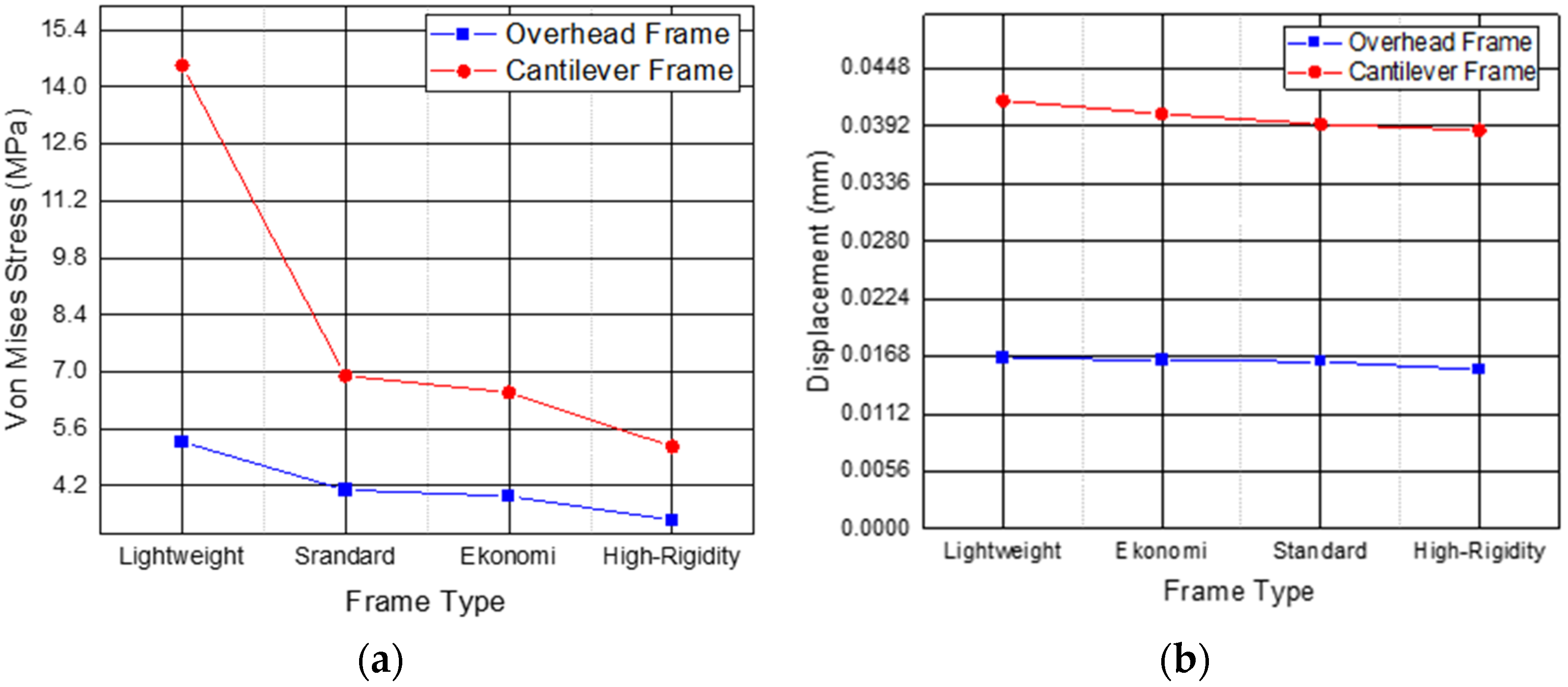
The results of the static load simulation on the von Mises stress parameters descend consecutively from the lightweight, standard, economic, and high-rigidity frame types, based on Table 5 and Table 6 and Figure 7a. Furthermore, we obtain a distinct form of a trend with the maximum stress trend due to the displacement value. Figure 7b shows that displacement values from the lightweight, economy, standard, and high-rigidity types decrease consecutively. The distinction in the standard and economic type frames sequence is reversed in the maximum stress value trend.
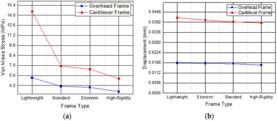
Figure 7.
Trend Line Result Comparison on Each Frame Type: (a) Von Mises Stress; (b) Displacement.
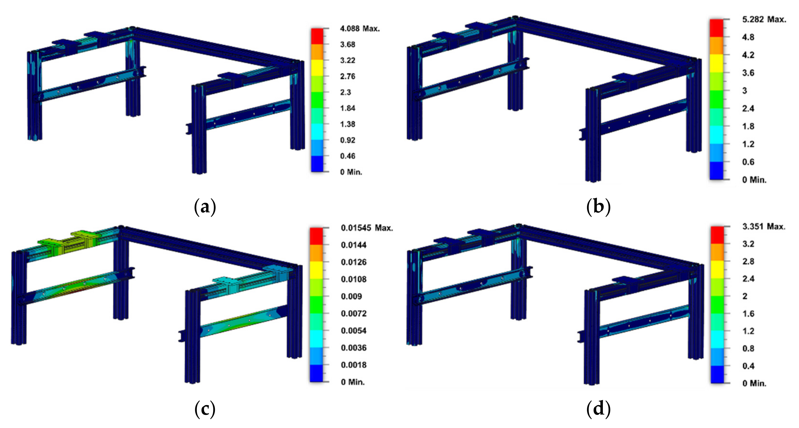
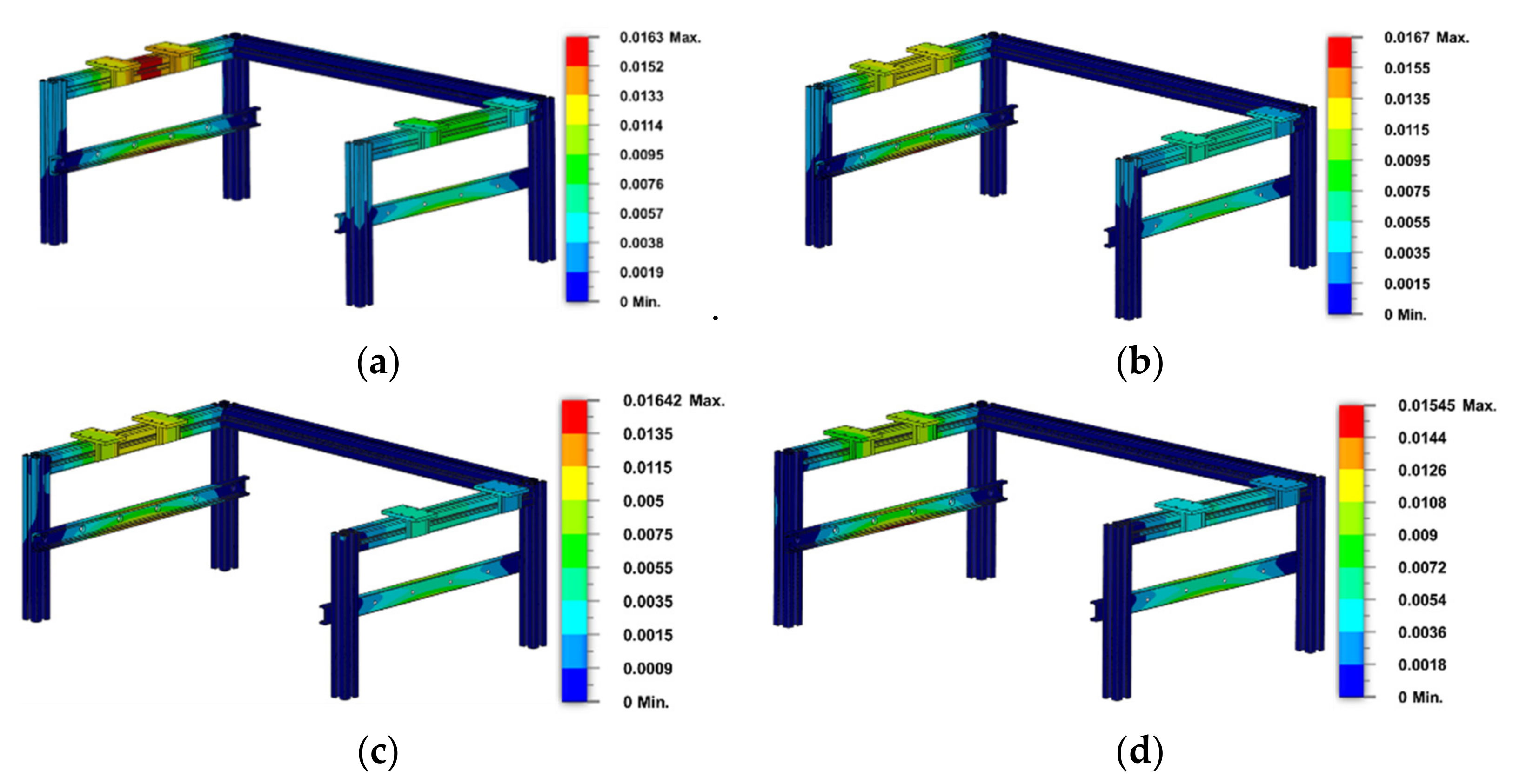
The safety factor is 15 for all material types of the overhead crane frame types, and this value is the maximum score for the safety factor. Thus, the frame type can safely withstand a given load. The standard frame type variation using the material A60N01S-T5 had a maximum tension of 4.09 N and a 16.3 × 10⁻³ mm displacement. The lightweight frame type acquired a 5.82 N maximum stress and a 16.7 × 10⁻³ mm displacement for the same material but with a different cross-sectional area. In the economic frame type variant, which uses A6063-T5, the maximum stress was 3.94 MPa and the displacement was 16.4 × 10⁻³ mm. While on the high-rigidity frame, the same material but different in the cross-sectional area gained a 3.35 MPa maximum stress and a 15.5 × 10⁻³ mm displacement. The maximum von Mises stress simulation results on the overhead crane can be seen in Figure 8, while the displacement results can be seen in Figure 9.
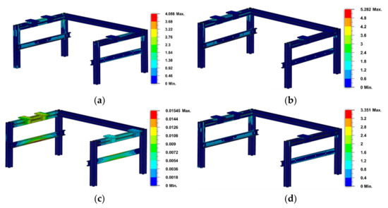
Figure 8.
Contour of Von Mises Stress on Overhead Crane: (a) Standard Type; (b) Lightweight Type; (c) Economy Type; (d) High-Rigidity Type.
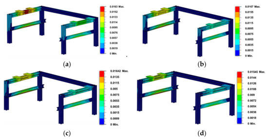
Figure 9.
Contour of Displacement on Overhead Crane: (a) Standard Type; (b) Lightweight Type; (c) Economy Type; (d) High-Rigidity Type.
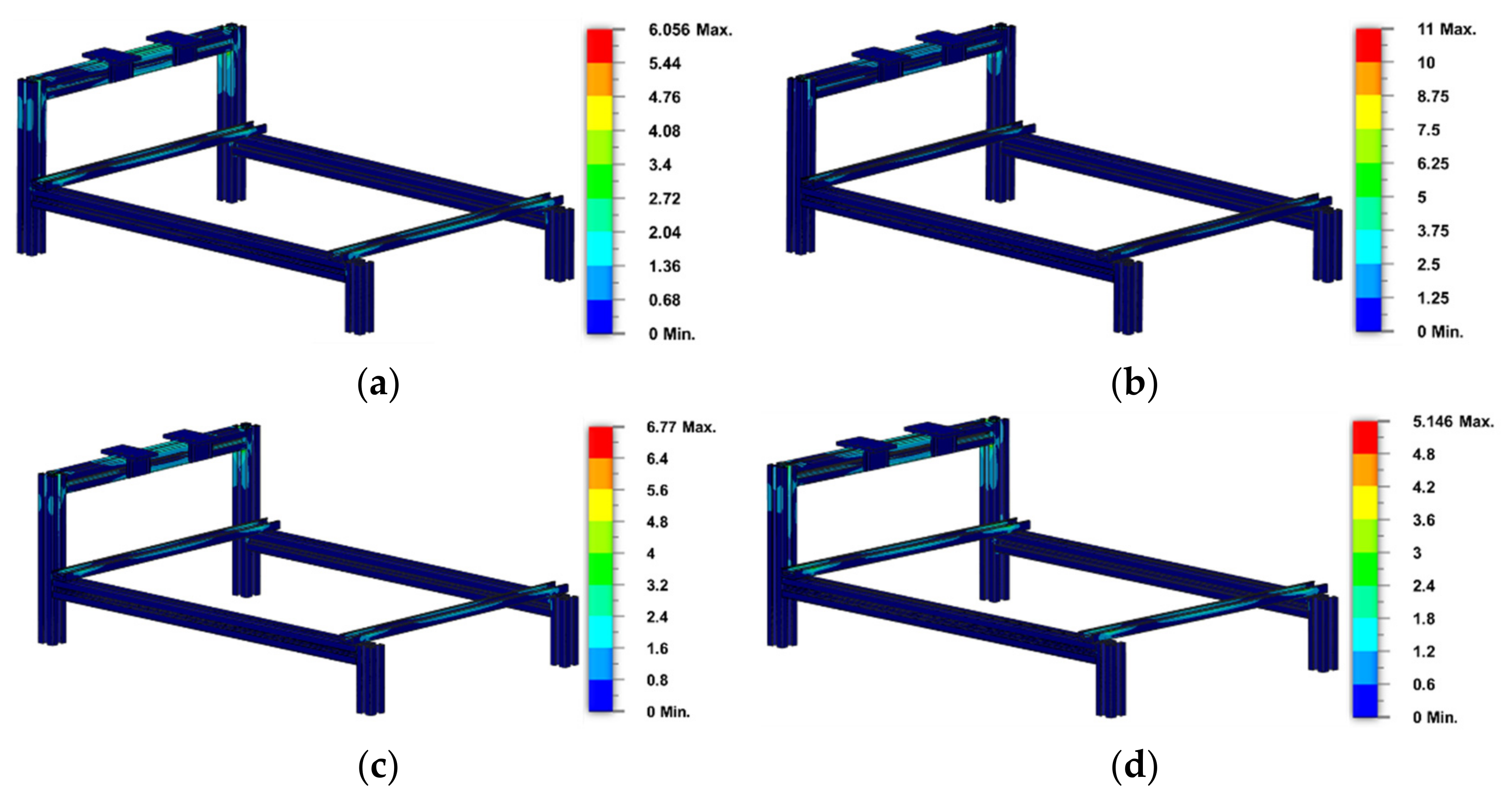
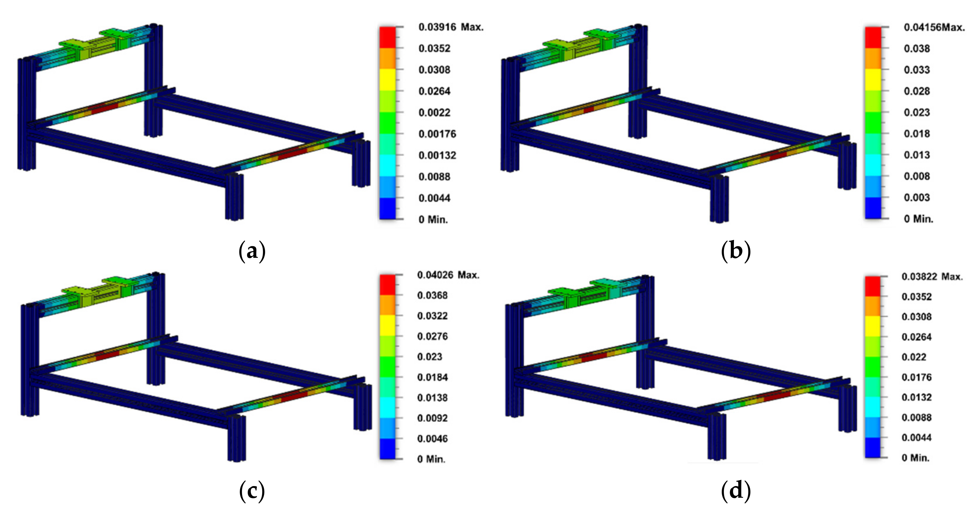
The same goes for all the cantilever crane frames with a safety factor of 15, and the standard structure type using material A6N01ST5 had a maximum stress of 6.9 MPa and gained 39.4 × 10⁻³ mm in displacement. The lightweight structure type gained a maximum stress of 14.53 MPa and a 41.7 × 10⁻³ mm displacement. Subsequently, the material A6063-T5 used for the economic structure gained a 6.46 MPa maximum stress and 40.4 × 10⁻³ mm displacement. The high-rigidity structure type gained a 5.16 MPa maximum stress and a 38.8 × 10⁻³ mm displacement for the same material. The maximum von Mises stress simulation results on the overhead crane can be seen in Figure 10, while the displacement results can be seen in Figure 11.
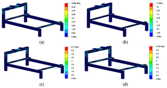
Figure 10.
Contour of Von Mises Stress on Cantilever Crane: (a) Standard Type; (b) Lightweight Type; (c) Economy Type; (d) High-Rigidity Type.
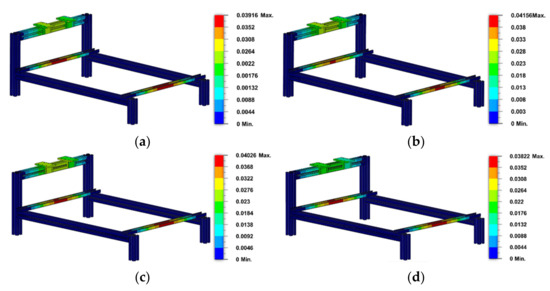
Figure 11.
Contour of Displacement on Cantilever Crane: (a) Standard Type; (b) Lightweight Type; (c) Economy Type; (d) High-Rigidity Type.
4.2. Checking Time Estimation for One Cycle Testing
By simulating the manual testing conditions with a digital screw micrometer and entering the test value into the computer, the authors determined that the average testing time for a single specimen was 18 s, based on ten manual tests. This value will be compared to the length of time required to test the brake pad thickness using an automatic tool so it can be determined whether the automatic machine is more efficient than the manual job or not.
4.2.1. Motor Speed Analysis
Festo’s type of servo motor with the EMMB-AS-40-01-K-S30SB series is used in this design because it has several advantages over other servo motor product lines, such as more effective prices and low maintenance costs. Moreover, there is a digital encoder to determine the location of the motor rotation.
From the data that are shown in Table 7 above, linear speed can be calculated by calculating the angular velocity from the rotation speed that has already been mentioned in the datasheet.

Table 7.
Technical Specification of Servo Motor.
As calculated in Equations (10) and (11) above, the angular velocity must be calculated first before the linear velocity, and it has a rate of . Meanwhile, as presented in the Festo datasheet, the maximum speed of the linear drives is . Thus, the maximum speed rate used in further calculations is the speed rate of the linear drive as a safe boundary and component capability.
4.2.2. Total Testing Time Estimation
- Time Estimation on Vertical Distance
The first step that must be taken in estimating the time for the vertical movement of the Festo component is to know the travel distance. The distance that needs to be known is the travel distance between the limit switch indenter and the brake pad surface, and then, it is known that the travel distance is 47 mm.
The first calculation is the time value when the sensor is heading and leaving the brake pad at a 47 mm, as in Figure 12. This calculation assumes a linear speed of 0.2 m/s and it is smaller than its maximum capability in order not to keep the precision in check.

Figure 12.
Distance of Indenter and Brake Pad Surface.
After figuring out how long it takes to speed up from 0 m/s to 0.2 m/s in Equation (12), it is necessary to know how far it went during that time.
Equation (13) above shows that the travel distance during acceleration is 0.0013 m. Then, the next step is to calculate the travel time for the rest of the distance that it gets through at a constant velocity of 0.2 m/s.
The total time for heading onto the brake pad is the sum of Equations (12) and (14), which is about 0.241 s. This value needs to be doubled to make the up and down motion in the test and needs to be multiplied by 15 due to the number of testing points.
Therefore, as calculated in Equation (16), the total time needed to perform one complete movement for heading and leaving the brake pad is 7.23 s.
- 2.
- Time Estimation on Testing Points in A Brake Pad
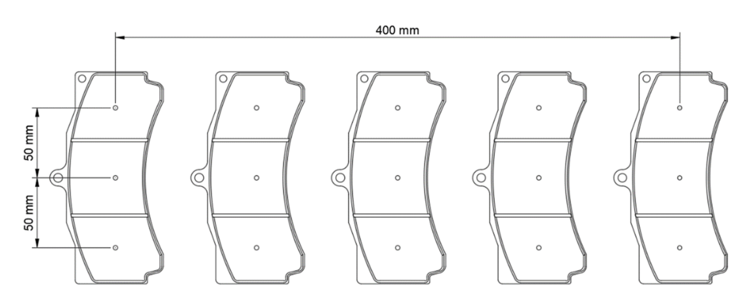
The second distance that needs to be known is the distance of the testing point inside a brake pad or between two pads. From Figure 13, it can be concluded that the distance inside a brake pad is known as 50 mm and 100 mm for the distance between two pads.
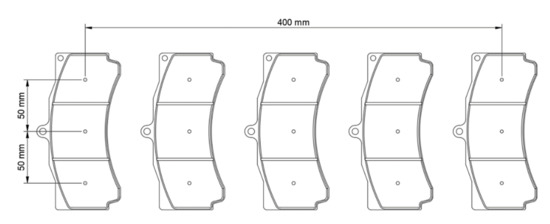
Figure 13.
Distance of Each Brake Pad and its Testing Points.
It would take ten moves between two checking points inside a pad and four moves for two different pads, as shown in Figure 13. This count of moves will be used in the travel time calculation with the assumption that the maximum 0.6 m/s linear velocity is used for the movement of the linear drive to speed up the total testing time.
From Equation (17), the travel time to move from 0 m/s to 0.6 m/s is 0.04 s; then, the travel distance during this time also needs to be calculated.
As mentioned in Equation (18), the travel distance that can be covered in an acceleration move is 0.012 m. Then, it would be necessary to determine the travel time at the remaining distance using only a constant speed of 0.6 m/s.
The time needed to move at a constant speed is 0.063 s, and it needs to be added up with Equation (17) to obtain the total travel time for one movement. In order to calculate the total time of 10 testing points, 0.103 s of travel time needs to be multiplied by 10.
Therefore, Equation (21) above says that the total time needed to accomplish the testing movement between the testing points in the brake pad is 1.03 s.
- 3.
- Time Estimation on Testing Points between Brake Pads
Based on Figure 14, the distance between two points on two brake pads is 100 mm, or 0.1 m, and this variable is needed to calculate the Festo part’s time to run on this track. If the value of the time while accelerating at rest is known, then the calculation process can be carried out starting from the distance that has not been passed.
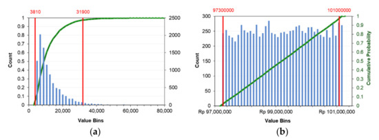
Figure 14.
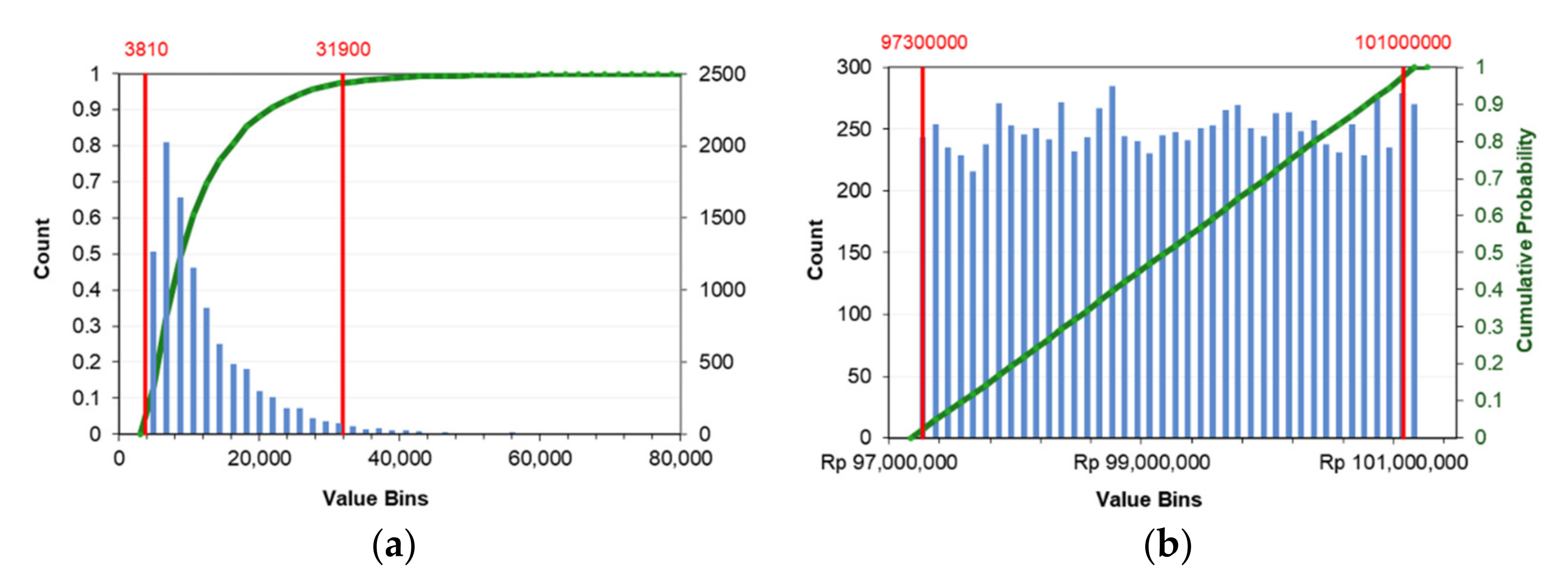
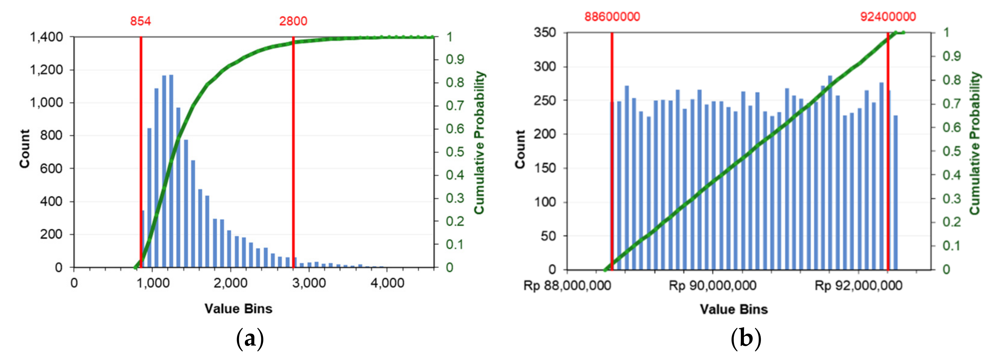
Histogram of BEP through MCS on Overhead Crane: (a) Break-Even of Units; (b) Break-Even Revenues.
The distance of 0.088 m, passed at constant velocity for 0.147 s, needs to be added up with the time for the acceleration movement in Equation (17). It afterwards also needs to be multiplied by four, as with the total movement between two testing points referred to in Figure 14.
As all the time components needed to carry out the testing aspects are known through Equations (16), (21), and (24), it is necessary to add up the time components to obtain the total estimation of the testing time.
Using the above equation, we can estimate that it will take about 9 s to test a set of five brake pads in one cycle.
By dividing the results in Equation (25) by five, the acquired time estimation for testing one brake pad will be 1.8 s according to Equation (26).
4.3. Investment Feasibility Analysis
4.3.1. Price Analysis
The cost estimation data below are generated from market research processes through the Festo and Misumi official websites and other suppliers in order to complete the building of an automatic brake pad thickness checking machine.
The cost estimation data for each type of mechanism shown in Table 8 are not very different from each other. Thus, the averaging process needs to be conducted for each mechanism to simplify the results of the break-even point and the simple payback period calculation (see Table 9).

Table 8.
Capital Cost for All Types of Overhead and Cantilever Crane Structure.

Table 9.
Average Capital Cost for Overhead and Cantilever Crane.
In addition, several prices arise when such equipment is procured to estimate the equipment cost. Some of these prices are explained in Table 10 below.

Table 10.
Extra Cost Detail of BEP and Payback Period on Monte Carlo Simulation.
One of the extra cost components that needs to be determined is the testing price of each brake. As this process is a part of the quality control, the price can be in the range of 5%–30% of the product price [26]. Market research on the price of brake pads that Akebono produces is carried out through the website of the official Akebono supplier [27]. Moreover, the estimated assembly and calibration costs are the estimation cost for one type of device to be ready for use.
4.3.2. Investment Feasibility Analysis for Overhead Crane Mechanism Design
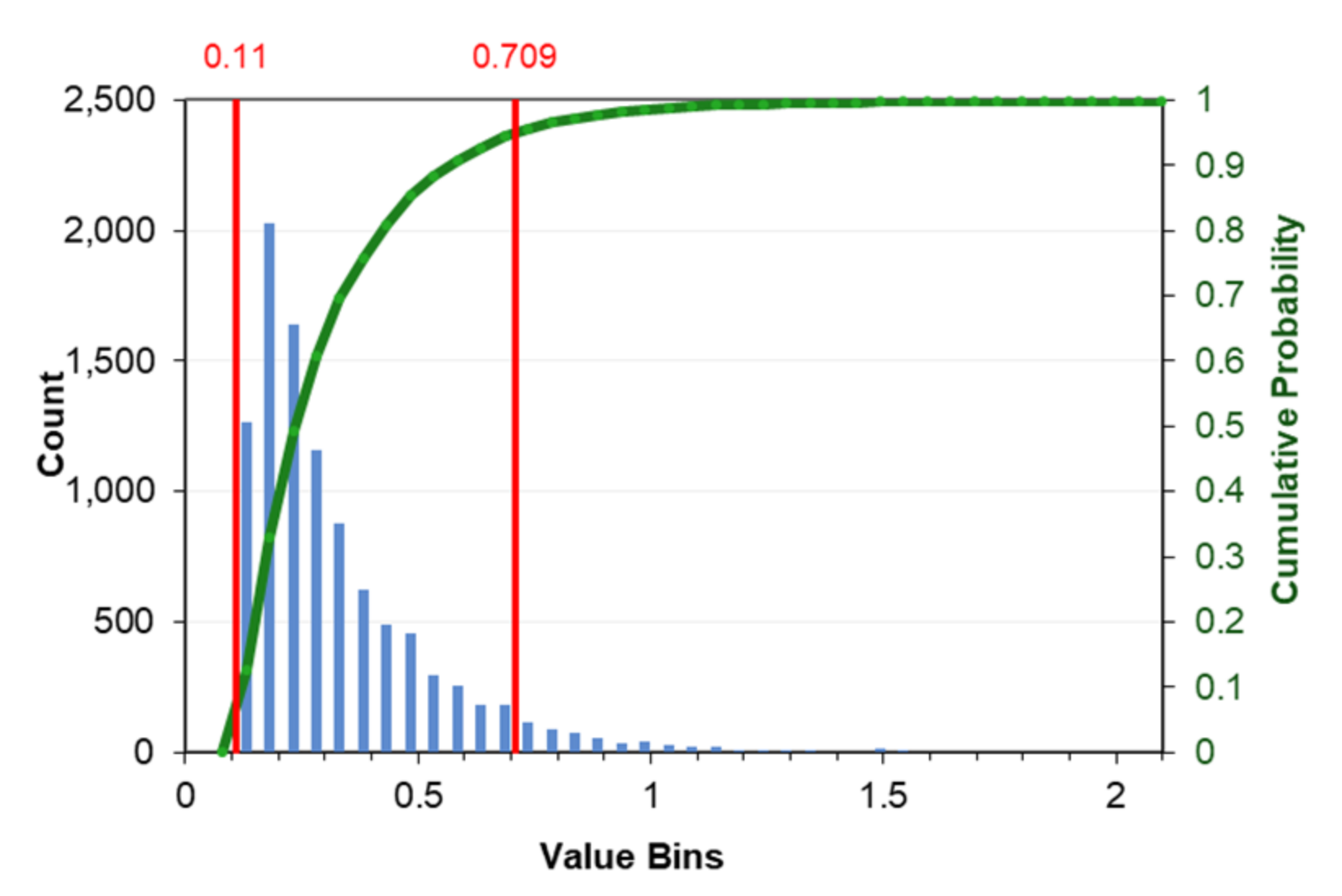
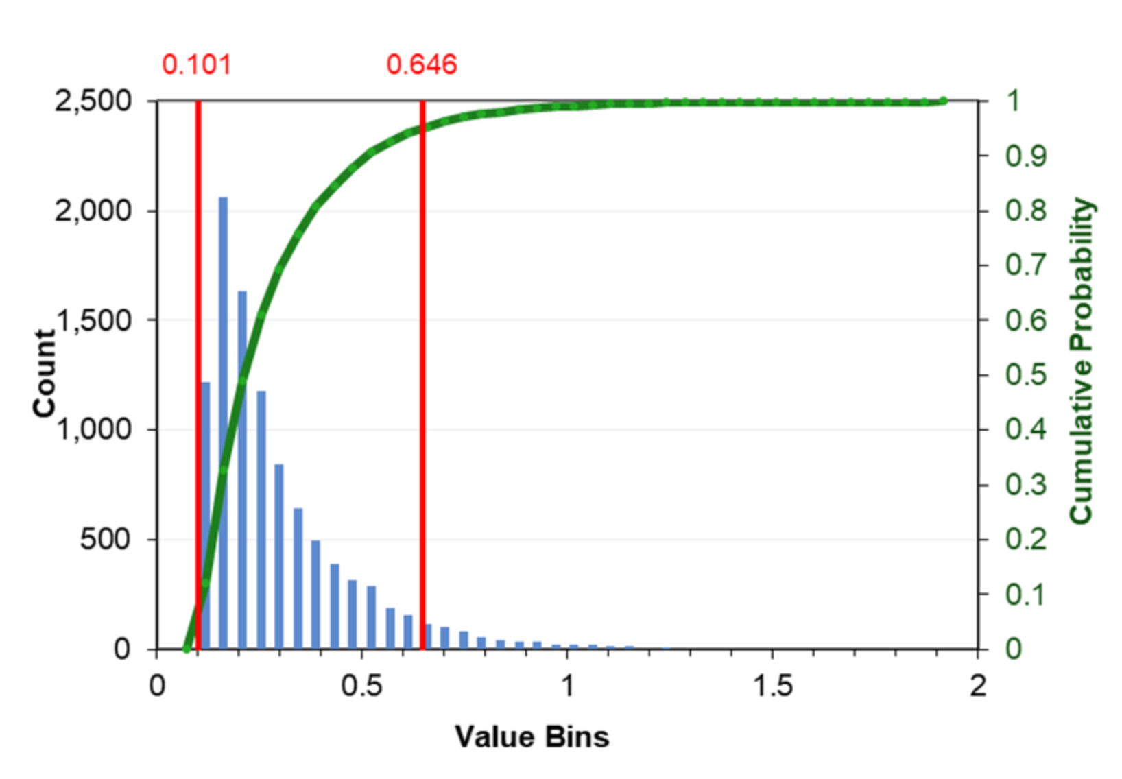
Despite the minimum and maximum prices of each type of investment feasibility, it will also be given a 2.5 percentile (Q1) as a realistic minimum price and a 97.5 percentile (Q2) as a realistic maximum price. The average value of the curve is also given as the most realistic value. The result of the Monte Carlo iteration for the break-even number of units, as shown in Figure 14a, has a diagram with a character that has a peak representing the most realistic price. This analysis has a minimum value of 3002 units, a maximum of 78,683 units, and a realistic value of 11,315 units. The BEP revenues in Figure 14b have a minimum value as great as IDR 97,168,313, a maximum value of IDR 101,168,150, and a realistic value of IDR 99,185,983. Figure 15 shows that the simple payback period analysis has a minimum of 0.08 months, a maximum of 2.1 months, and a realistic time of 0.3 months.
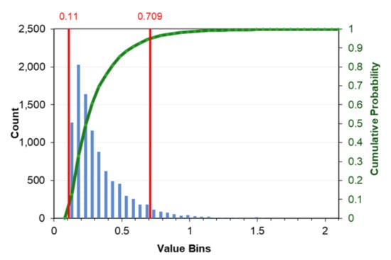
Figure 15.
Histogram of Simple Payback Period through MCS on Overhead Crane.
4.3.3. Investment Feasibility Analysis for Cantilever Crane Mechanism Design
The cantilever crane mechanism has a lower average capital cost than the overhead crane mechanism. Therefore, this lower cost will impact the unit that needs to be checked and the money that needs to be earned to achieve the break-even point and impact the length of the simple payback period time with the same cash flow as the iteration used in the overhead crane before.
As shown in Figure 16a, the result of the Monte Carlo iteration for the number of units at the break-even point also has a peak on its chart that represents the most realistic price. The minimum value for this analysis is 778 units, the maximum value is 4488 units, and the realistic value of 1424. The break-even revenue in Figure 16b shows that the minimum value is IDR 88,515,482, the maximum value is IDR 92,514,598, and the most realistic value is IDR 90,519,894. The simple payback period analysis shown in Figure 17 concluded that the minimum time is 0.07 months, the maximum time is 1.87 months, and the most realistic value from this iteration is gained at 0.27 months.
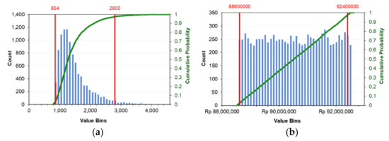
Figure 16.
Histogram of BEP through MCS on Cantilever Crane: (a) Break-Even of Units; (b) Break-Even Revenues.
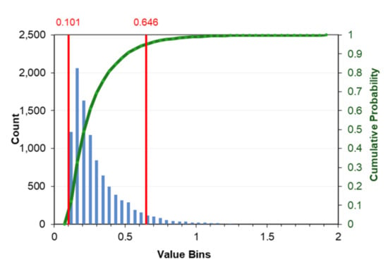
Figure 17.
Histogram of Simple Payback Period through MCS on Cantilever Crane.
4.4. Overview of the Result
The data of the testing time estimation and investment analysis provided from the iteration in Section 4.2 and Section 4.3 are very descriptive and difficult to compare between the variables. Thus, to address the issues, it is necessary to make a comparison table of the provided results. Table 11 below compares the testing time estimation, the BEP of the units, the BEP revenues, and the payback period of the overhead crane and cantilever crane models.

Table 11.
Summary of the Results of Overhead Crane and Cantilever Crane.
5. Discussion
Time efficiency in the mass checking of the brake pad thickness is the main problem in the dimensional test category in the quality control process at the brake pad company. Optimizing the time efficiency can be carried out by speeding up the testing time. Providing a machine that works automatically is one of the solutions [28,29].
The results indicate that the automatic brake pad checking machine is viable for use as a production machine in the quality control area because its structural frame can handle the loads of the moving part, and it is able to check five brake pads in one test cycle. Comparing this result with the existing methods is a significant improvement because the previous method could only perform one brake pad test per cycle, either by the manual method or by ultrasound [10,11]. Apart from the ability to check five brake pads in one cycle, the time estimation of checking one brake pad in this study is 1.8 s. It is faster than the current manual method, approximately 18 s, including recording the data on a computer.
The importance of the feasibility studies has made this research necessary to analyze them. In a study conducted by Ionut [15], it was discovered that a feasibility study is a tool that can provide technical, economic, and financial justification for an investment project decision. Furthermore, it showed that the BEP and payback period are reasonably effective in achieving capital growth rates [14]. Those two findings have become a reference in this research to provide technical justification in the form of technical design, structural strength analysis, testing time estimation to ensure that the test will be profitable, and a BEP analysis and payback period. It was found that the payback period in this study can be achieved in a short amount of time because the sample calculation uses an example of a company with a large number of capacities
It must be admitted that the design of this tool has the disadvantage of requiring more expensive costs compared to manual testing using a caliper. The limited ability of the sensor, which can only measure distance, makes it an advantage to optimize one function. However, it does not have many roles compared to previous studies utilizing ultrasound, which can measure underlying mechanical properties.
6. Conclusions
This study aimed to provide an overview of the importance of checking the thickness of brake pads and to provide a solution to solve the problem of thickness checking over massive quantities in the quality control process. The results indicate that an automatic brake pad thickness checking machine with a 3-axis mechanism, either an overhead crane system or a cantilever crane, is easy to manufacture and assemble because it contains very few custom-made components. Moreover, all the variations of the aluminum frame used have proven to be strong in finite element simulations to support drive components and also several supporting components for the automatic brake pad thickness. The time required to perform the thickness test has also been shown to be up to 10 times faster when compared to manual testing using a digital caliper. In addition to the technical aspects, the economic aspects must be considered if a company uses this tool as a production machine. With simple investment feasibility results showing the short time to get the capital back and achieve BEP, all the machines can be said to be feasible to use within a few years. Even though there are differences in the average test results of the components with the overhead and cantilever crane mechanisms, there is no significant difference between the types of frames with the exact mechanism.
In order to maximize the present work and support the sustainability of the research, the physical prototype machine from this work is taken into consideration as material for the following research. The professional feedback from the brake pad industry is important to make a better one that suits the test function. Furthermore, another brake pad test mechanism can be developed into an automated system, with several types of tests, such as those for density, hardness, and physical aspects, and other tests. Connecting two automatic test methods in an automatic way might be needed to optimize the quality control flow. A previous study in automatic brake pad hardness checking [30] is one of the currently available studies on brake pad checking, which can be connected with other tests in further research.
Author Contributions
Conceptualization, M.F.D., A.R.P., F.I., I.Y. and J.H.C.; methodology, M.F.D., A.R.P., F.I., I.Y. and T.M.; software, M.F.D., W.E.J. and D.D.D.P.T.; validation, M.F.D., W.E.J. and J.H.C.; formal analysis, A.R.P., D.D.D.P.T. and J.H.C.; investigation, M.F.D., F.I., W.E.J. and J.H.C.; resources, M.F.D., A.R.P. and D.D.D.P.T.; data curation, M.F.D., D.D.D.P.T. and T.M.; writing—original draft preparation, M.F.D., A.R.P. and F.I.; writing—review and editing, M.F.D., A.R.P. and F.I.; visualization, M.F.D., I.Y., D.D.D.P.T. and T.M.; supervision, A.R.P. and F.I.; project administration, A.R.P. and I.Y.; funding acquisition, A.R.P., I.Y., D.D.D.P.T., W.E.J. and T.M. All authors have read and agreed to the published version of the manuscript.
Funding
This research is funded by Universitas Sebelas Maret under the funding scheme Kolaborasi Internasional (KI-UNS) with contract/grant number 254/UN27.22/PT.01.03/2022. The grant is gratefully acknowledged by the authors.
Institutional Review Board Statement
Not applicable.
Informed Consent Statement
Not applicable.
Data Availability Statement
The authors declare that the data supporting the findings of this study are available within the article.
Conflicts of Interest
The authors declare no conflict of interest.
References
- Papinniemi, A.; Lai, J.C.S.; Zhao, J.; Loader, L. Brake Squeal: A Literature Review. Appl. Acoust. 2002, 63, 391–400. [Google Scholar] [CrossRef]
- Wei, L.; Choy, Y.S.; Cheung, C.S. A Study of Brake Contact Pairs under Different Friction Conditions with Respect to Characteristics of Brake Pad Surfaces. Tribol. Int. 2019, 138, 99–110. [Google Scholar] [CrossRef]
- Kinkaid, N.M.; O’Reilly, O.M.; Papadopoulos, P. Automotive Disc Brake Squeal. J. Sound Vib. 2003, 267, 105–166. [Google Scholar] [CrossRef]
- Ghazaly, N.M.; El-Sharkawy, M.; Ahmed, I. A Review of Automotive Brake Squeal Mechanisms. J. Mech. Des. Vib. 2013, 1, 5–9. [Google Scholar]
- Hussin, M.H.; Bakar, A.R.A.; Jamaluddin, M.R.; Szlapka, R. Effects of Lining Thickness on Squeal in Drum Brake Assembly: Experimental Investigations. Int. J. Veh. Struct. Syst. 2010, 2, 69–73. [Google Scholar] [CrossRef][Green Version]
- Abendroth, H.; Wernitz, B. The Integrated Test Concept: Dyno—Vehicle, Performance—Noise; Technical Paper; SAE International: Warrendale, PA, USA, 2000. [Google Scholar] [CrossRef]
- Nishizawa, Y.; Kosaka, K.; Kurita, Y.; Oura, Y. Influence of Pad Thickness and Surface Roughness on Pad Stiffness; Technical Paper; SAE International: Warrendale, PA, USA, 2012; Volume 7. [Google Scholar]
- Oura, Y.; Kurita, Y.; Nishizawa, Y.; Kosaka, K. Influence of Brake Pad Thickness on Disk Brake Squeal. J. Syst. Des. Dyn. 2010, 4, 970–983. [Google Scholar] [CrossRef][Green Version]
- Steege, R.; Marx, F. A New Approach to Material Compressibility of Brake Pads; Technical Paper; SAE International: Warrendale, PA, USA, 2008. [Google Scholar] [CrossRef]
- Yuhas, D.E.; Gesch, E.; Yamane, T.; Vorres, C.; Remiasz, J. Comparative Studies of Non-Destructive Methods for As-Manufactured Brake Pads; Technical Paper; SAE International: Warrendale, PA, USA, 2010. [Google Scholar] [CrossRef]
- Yuhas, D.E.; Vorres, C.L.; Remiasz, J.R.; Gesch, E.; Yamane, T.; Corporation, P.F. Non-Destructive Ultrasonic Methods for Quality Assurance of Brake Pads. In Proceedings of the Eurobreak 2012 International Conference, Dresden, Germany, 16–18 April 2012; pp. 1–10. [Google Scholar]
- Every, A.G. Determination of The Elastic Constants of Anisotropic Solids. NDT E Int. 1993, 27, 3–10. [Google Scholar] [CrossRef]
- Ihuoma, D.N.; Lilly, M.T.; Ndor, M.V. The Impact of Quality Control for Profitability in a Car Brake Pad Manufacturing Industry: A Case Study. Int. J. Sci. Eng. Invent. 2018, 4, 125. [Google Scholar] [CrossRef]
- Lohmann, J.R.; Baksh, S.N. The IRR, NPV, and Payback Period and Their Relative Performance in Common Capitial Budgeting Decision Procedures for Dealing with Risk. Eng. Econ. 1993, 39, 17–47. [Google Scholar] [CrossRef]
- Ionut, C. The Importance of The Feasibility Study for The Business Plan. Ann. Econ. Ser. 2015, Special, 515–519. [Google Scholar]
- Mott, R.L.; Vavrek, E.M. Machine Elements in Mechanical Design, 6th ed.; Pearson: New York, NY, USA, 2018; ISBN 9780134441184. [Google Scholar]
- Xu, K.; Liu, H.; Xiao, J. Static Deflection Modeling of Combined Flexible Beams Using Elliptic Integral Solution. Int. J. Non Linear Mech. 2021, 129, 103637. [Google Scholar] [CrossRef]
- Richard, G.B.J.; Keith, N. Shigley’s Mechanical Engineering Design; McGraw-Hill: New York, NY, USA, 2005; ISBN 9780073398204. [Google Scholar]
- Dewobroto, W.S. Penggunaan Business Model Canvas Sebagai Dasar Untuk Menciptakan Alternatif Strategi Bisnis Dan Kelayakan Usaha. J. Tek. Ind. 2012, 2, 215–230. [Google Scholar] [CrossRef]
- Horngren, C.T.; Datar, S.M.; Rajan, M. Cost Accounting: A Managerial Emphasis; Pearson: Upper Saddle River, NJ, USA, 2011; ISBN 978-0-13-210917-8. [Google Scholar]
- Previo Caesar, B.P.; Istanto, I.; Pratama, P.S.; Cho, J.H.; Prabowo, A.R. Improvement of Auto Checking Hardness Machine Using Several Material Series of Aluminum Structural Frame: Case Study on Mitutoyo HR-522 Hardness Tester. Procedia Struct. Integr. 2020, 27, 117–124. [Google Scholar] [CrossRef]
- Durst, P.J.; Mcinnis, D.; Davis, J.; Goodin, C.T. Simulation Modelling Practice and Theory A Novel Framework for Verification and Validation of Simulations of Autonomous Robots. Simul. Model. Pract. Theory 2022, 117, 102515. [Google Scholar] [CrossRef]
- Szabó, B.; Babuška, I. Introduction to Finite Element Analysis: Formulation, Verification and Validation; John Wiley & Sons, Ltd.: New Delhi, India, 2011; ISBN 9780470977286. [Google Scholar]
- Previo, B.P.; Dzulfikar, M.F.; Pratama, P.S. Analysis of Anauto Checking Hardness Machine—A Study Case Design Development and Technical Analysis of An Auto Checking Hardness Machine. J. Appl. Eng. Sci. 2021, 19, 731–742. [Google Scholar] [CrossRef]
- Fajar, M.; Lestari, Y.D. Aggregate Planning Analysis in PT. Akebono Brake ASTRA Indonesia. J. Bus. Manag. 2017, 6, 182–191. [Google Scholar]
- Williams, A.R.T.; Van Der Wiele, A.; Dale, B.G. Quality Costing: A Management Review. Int. J. Manag. Rev. 1999, 1, 441–460. [Google Scholar] [CrossRef]
- AstraOtoshop Akebono Brake Pads Catalogue. Available online: https://www.astraotoshop.com/brand/akebono.html (accessed on 1 April 2020).
- Afolalu, S.A.; Ikumapayi, O.M.; Abdulkareem, A.; Soetan, S.B.; Emetere, M.E.; Ongbali, S.O. Enviable Roles of Manufacturing Processes in Sustainable Fourth Industrial Revolution—A Case Study of Mechatronics. Mater. Today Proc. 2021, 44, 2895–2901. [Google Scholar] [CrossRef]
- Febriani, R.A.; Park, H.S.; Lee, C.M. A Rule-Based System for Quality Control in Brake Disc Production Lines. Appl. Sci. 2020, 10, 6565. [Google Scholar] [CrossRef]
- Caesar, B.P.P.; Hazimi, H.; Sukanto, H.; Prabowo, A.R. Development of Novel Design and Frame Structural Assessment on Mitutoyo’s Auto Checking Hardness Machine Using Reverse Engineering Approach: Series HR-522 Hardness Tester. J. Eng. Sci. Technol. 2020, 15, 1296–1318. [Google Scholar]
Publisher’s Note: MDPI stays neutral with regard to jurisdictional claims in published maps and institutional affiliations. |
© 2022 by the authors. Licensee MDPI, Basel, Switzerland. This article is an open access article distributed under the terms and conditions of the Creative Commons Attribution (CC BY) license (https://creativecommons.org/licenses/by/4.0/).

