Article

Difference between Pavement Thickness Design and Pavement Life Prediction for Rigid Aircraft Pavements

School of Science, Technology and Engineering, University of the Sunshine Coast, Sunshine Coast, QLD 4556, Australia
Designs 2022, 6(1), 12; https://doi.org/10.3390/designs6010012
Submission received: 6 January 2022 / Revised: 27 January 2022 / Accepted: 31 January 2022 / Published: 4 February 2022
(This article belongs to the Section Civil Engineering Design)

Abstract

:
Aircraft pavements are generally designed using deterministic methods and using conservatively selected input parameter values, which combine to result in a low probability of structural failure occurring during the structural design life of the pavement. In contrast, when predicting the actual time until an as-constructed pavement will reach a structural failure condition, stochastic methods are required to take into account the inherently variable nature of pavement material properties and layer thicknesses, and the best-estimate of the input parameter values must replace the conservative values that are commonly used to introduce design reliability. A case study on a rigid aircraft pavement demonstrates the difference between pavement thickness design and pavement life prediction. Using Monte Carlo simulation, it was found that 98.5% of the as-constructed pavement was stronger than the designed pavement and that the predicted fatigue life of the pavement was approximately 180 times greater than the effective design life. It was concluded that the significant difference between pavement design and pavement life prediction explains the practical observation that rigid aircraft pavement service life generally exceeds typical structural design lives.

1. Introduction

Aircraft pavements are generally designed using conservative methods that result in a low risk of structural failure occurring during the design life of the pavement [1]. Consequently, most aircraft pavements experience satisfactory performance over a service life that significantly exceeds the design life [2]. For example, flexible aircraft pavements are effectively perpetual in nature, with periodic asphalt overlays resetting the design life, while the underlying structure lasts many decades, despite a typical 15- to 20-year structural design life [3]. Similarly, rigid aircraft pavements are generally designed to achieve a 20-year (in the USA) or a 40-year (in Australia) structural design life, but there are many examples of 50- to 70-year-old rigid aircraft pavements that remain in service [4].
In terms of rigid aircraft pavement failure, two modes of failure must be considered. The first is serviceability failure, and the second is structural failure [2]. Serviceability failure can result from excessive pavement generated foreign object debris (FOD) due to construction defects, from excessive unevenness in the slabs due to reactive subgrade movement, or even the loss of aircraft skid resistance or visual guidance from linemarking. Serviceability failure modes are not directly considered during pavement thickness design. In contrast, the structural failure of aircraft pavements is the basis on which pavement thickness design calculations are performed, and for rigid aircraft pavements, the only form of structural failure considered in thickness design is concrete slab fatigue cracking [5]. Because rigid aircraft pavements are designed conservatively and remain serviceable for many years beyond their structural design life, it follows that the fatigue failure of rigid aircraft pavements usually occurs much later than implied by aircraft pavement thickness design processes. That is, rigid aircraft pavements generally do not deteriorate to the pre-defined structurally failed condition by the end of their structural design life.
The aim of this research was to demonstrate and quantify the difference between pavement thickness design and pavement life prediction. A case study is presented in the form of a rigid aircraft pavement located in Queensland, Australia, which was designed and constructed, but then due to post-construction concerns, the design was revisited to predict the time until slab fatigue failure would occur.

2. Background

2.1. Rigid Aircraft Pavements

Constructed primarily of slabs of Portland or blended cement concrete, usually with a relatively thin sub-base (sometimes referred to as the base) to support the slabs, rigid aircraft pavements show insignificant deformation under load compared to flexible aircraft pavements [2]. Rather than spreading the load through the sub-base and subgrade materials, rigid pavements primarily resist the load-induced stresses internally within the concrete slabs.
Rigid aircraft pavement slabs are generally small (4 to 6 m square) in relation to the area of the pavement. Joints are provided to relieve environmental stresses caused by thermal and moisture changes [6]. However, the joints create stress concentrations at the edges and corners of the slab, and the concentrated stresses are often critical for rigid pavement performance [7]. Rigid pavement slabs also experience curling due to temperature differentials between the top and bottom of the concrete slab. During the day, the top of the slab is warmed by the sun and expands, making the top of the slab longer than the bottom, curling the slab downwards. During the night, the top of the slab cools and shortens, resulting in upward curling. Accurately determining curling (upward and downward) stresses is difficult, and pavement thickness design does not directly account for these environmental loads.

2.2. Rigid Aircraft Pavement Thickness Design

Similar to most modern pavements, rigid aircraft pavement thickness is generally determined using mechanistic-empirical methods. That is, key stresses and strains are theoretically calculated mechanistically, before the allowable number of repetitions of that magnitude of stress or strain is determined by empirically derived ‘failure criteria’, which are also known as the ‘performance relationships’, and less commonly as ‘transform functions’ [7].
FAARFIELD is the FAA’s current pavement thickness design software for both rigid and flexible aircraft pavements [1]. FAARFIELD (v1.3) replaced the previous software, LEDFAA, when the FAA’s associated design guidance was updated in 2009 [8]. The 2009 edition was the first to not include historical chart-based design methods, completing the FAA’s transition to the software-based thickness design of aircraft pavements. However, the failure criteria in FAARFIELD v1.3 were developed to retain general agreement with pavement thicknesses determined by the previous design charts, in which the FAA had significant experience and a high level of confidence.
A major revision of FAARFIELD (v1.4.1) was released in 2016, corresponding to another major update to the design guidance (FAA 2016). Significant changes were made to the rigid pavement design module, reflecting analysis of the result from additional full-scale tests performed by the FAA, known as construction cycles CC2 and CC6 [9]. Important changes included improved finite element meshing, changes to granular sub-base modulus assignment, changes in the conversion between subgrade CBR, the modulus of subgrade reaction (k-value), and the elastic modulus [10]. However, the most important change to rigid pavement design in v1.4.1 was the introduction of a second potential critical stress location [4]. In addition to 75% of the maximum edge stress, traditionally the critical stress for rigid pavement thickness design, the maximum interior slab stress was also considered. That is, the calculation of concrete thickness was based on the greater of the maximum internal stress and 75% of the maximum edge stress [10]. It is understood by this reflected observation that sometimes the internal stress condition is more critical than the edge stress condition, particularly for the newer four- and six-wheeled aircraft gears. As a result, there are not many correlations between FAARFIELD 1.4.2 and FAARFIELD 1.3. rigid pavement thickness compared to the high number of correlations for flexible pavement thickness [11].
One consequence of this change was a significant increase in rigid pavement thickness associated with six wheeled aircraft gears, such as that of the B777-300ER. Subsequently, the FAA updated FAARFIELD (v1.4.2) [12], which reduced the internal stress condition by 5%. That is, the concrete thickness in v1.4.2 is calculated based on the greater of 95% of the maximum internal stress and 75% of the maximum edge stress. This reduces the concrete thickness required for designs governed by the internal stress condition but has little or no effect on designs governed by the edge stress condition. The FAA introduced FAARFIELD 2.0 in 2020, which includes a new user interface and supports the new international aircraft pavement strength rating system [13]. However, FAARFIELD 1.4.2 was used for this research.

2.3. Design Input Parameters

Once the aircraft traffic load spectrum is determined, along with the associated structural design life, the input parameters required for a new rigid pavement thickness design in FAARFIELD include:
  • Subgrade modulus: Entered as an elastic modulus (MPa) but usually converted from CBR (%), usually ranging from CBR 3 to CBR 15.
  • Sub-base material and thickness: Usually either fine-crushed rock (P-209) or cement-treated base (P-304) and usually 150 mm or 200 mm thick, although other materials are sometimes used.
  • Concrete strength: Entered as a flexural strength (MPa) and usually ranges from 3.5 MPa to 5.5 MPa.
The sub-base material modulus is fixed in FAARFIELD; however, the sub-base thickness can be modified within limits, although sub-base thickness has a relatively low influence on rigid pavement thickness [4]. In contrast, subgrade modulus and concrete strength are inherently variable and can be modified in FAARFIELD. These parameters also have significant influence on the pavement thickness [4]. In fact, the conservative selection of the subgrade modulus and concrete strength is the primary source of design reliability in rigid pavement thickness calculation, with a characteristic- or percentile- (%-ile) based approach usually applied to both.
The basis for selecting both the subgrade modulus and the concrete flexural strength is summarised in Table 1. It is noted that Australia and the USA use a different basis for defining the characteristic strength of concrete. Neither is right or wrong; it is just different, and this means that 20% of concrete falls below the characteristic strength value in the USA, while 5% falls below the characteristic value in Australia. Consequently, when FAARFIELD, which was developed in harmony with material specifications used by the FAA in the USA, is used to design rigid aircraft pavements in Australia using an Australian-specified concrete strength, a correction to the concrete strength input into FAARFIELD is required, which equates to approximately 0.3 MPa to 0.4 MPa, depending on the expected variability of the supplied concrete strength (Figure 1).

2.4. Monte Carlo Simulation

FAARFIELD and most other pavement thickness softwares are deterministic. That is, they are designed for the specific values of each input parameter to be entered by the designer. For example, the designer can select any reasonable value for the subgrade modulus, but only one subgrade modulus is able to the entered at a time. In reality, many of the input parameters are inherently variable, but the variable nature of the parameters cannot be directly considered in FAARFIELD. This is not an issue during routine pavement thickness design because the designer selects conservative representative or characteristic values to be input to determine an appropriate design pavement thickness. However, when interested in predicting the structural life of an existing pavement, the variable nature of the input parameters must be taken into account through a stochastic analysis. Because FAARFIELD does not accept stochastic input parameter value distributions, a Monte Carlo type analysis is required.
Monte Carlo simulation is the process of developing a deterministic predictive model of the output of interest and assigning probability distributions to each of the variable and measurable inputs [14]. By generating random but statistically appropriate combinations of input values that conform to these distributions, a large number of deterministic outputs can be calculated quickly. The resulting distribution of the results allows a stochastic analysis of a system that is too complex to be considered one input at a time. Such simulations were made practically viable by the rapid increase in computational power in the 1990s [15] and are now commonplace in many industries. In pavement engineering, the Monte Carlo simulation has been used to consider a stochastic approach to pavement thickness design [16], to better understand the effect of material variability on pavement performance [17], and for assessing the as-constructed strength of newly constructed pavements [18,19]. There are many software programmes available for performing Monte Carlo simulations, such as the Microsoft Excel®-based package @RISK® [20].

2.5. Thickness Design versus Life Prediction

During new rigid pavement thickness design, the aim is to determine a thickness of a concrete slab that means that the probability of the pavement deteriorating to a ‘failed’ condition during the structural design life is sufficiently low. The probability that coincides with ‘sufficiently low’ is determined by the failure criteria is also built into the software, as is the %-ile basis used by the designer to select the characteristic values of the subgrade modulus and the concrete strength (Table 1). As explained above, Australian and USA practice is to use an 85%-ile value of the subgrade modulus and an 80%-ile (USA) or a 95%-ile (Australia) value of concrete flexural strength. This combination of subgrade support and concrete strength provides a significant reduction in the probability of structural failure in a rigid aircraft pavement.
In the case of rigid aircraft pavements designed using FAARFIELD, the only failure condition considered is full depth structural cracking resulting from aircraft load induced slab fatigue. This is the only empirical mode of failure addressed by the FAARFIELD failure criteria [5]. Consequently, in combination with the conservative selection of the input values, the setting of the FAARFIELD concrete fatigue failure criteria determines the condition of a pavement that should be observed at the end of the design aircraft loading.
The setting of the failure criteria requires two elements to be considered: the condition of a pavement that is considered to constitute ‘structural failure’ as well as the level of design reliability built into FAARFIELD, which is defined by the location of the failure criteria within the data set of empirical test pavement sections. The FAARFIELD rigid pavement failure criteria are a structural condition index (SCI) of 80 [10]. That corresponds to approximately 50% of the most frequently trafficked slabs having one or more full-depth structural cracks. For any particular test pavement section, the SCI starts at 100. After a number of loadings, the SCI falls below 100 when the first crack appears. Cracks continue to develop until the pavement is completely failed, at an SCI of 0, which is when the pavement has lost its ability to carry any load [9], as shown by the example in Figure 2.
After many versions of Figure 2 are generated for different test pavement sections, the number of load repetitions until the first crack appears (SCI first drops below 100) and full failure (SCI is 0) can both the plotted, and the failure criteria can be located within the data sets, such as the example in Figure 3, which is a best-fit failure criteria with 50% of the results above the best-fit line, and 50% of the results below it. LEDFAA, which was the precursor to FAARFIELD, used a best-fit failure criteria location, meaning that 50% of the test pavements performed better and 50% performed worse than the performance implied by the failure criteria [5]. However, in FAARFIELD 1.4, an 85%-ile failure criteria location was also developed and the software transitions from the 50%-ile criteria (for CBR 3 and below) to the 85%-ile criteria (for CBR 10 and above) [10]. This is intended to reduce the risk of top-down cracking, which is not otherwise considered in FAARFIELD, but has been observed in test pavement sections on high-bearing capacity subgrades [10].
As a result of the ‘failure’ condition and best-fit ‘location’ of the rigid pavement fatigue failure criteria used in FAARFIELD, a theoretical pavement that is designed in FAARIELD and is then constructed homogenously with materials, thicknesses, and property values exactly as entered into FAARFIELD should reach the FAARFIELD failure condition at the end of the design trafficking loadings, which should occur at the end of the structural design life. That is, approximately 50% of the frequently trafficked slabs would exhibit one or more full-depth structural cracks at the end of the structural design life. Furthermore, of all of the theoretical pavements constructed in such a manner, 50% should perform better than expected with regard to slab fatigue, and the other 50% should perform below expectations, with more than 50% of the trafficked slabs containing one or more structural cracks.
In practice, having a 50% chance that 50% of the trafficked slabs will be cracked at the end of the design life is unacceptable, and this is not reflected in the generally better than expected performance of rigid aircraft pavements in the field [2]. The ‘better than designed’ fatigue performance of rigid aircraft pavement results from the conservative %-ile-based selection of the input parameter values, primarily the subgrade modulus and concrete flexural strength, to introduce design reliability. In practice, additional design reliability is also likely to be introduced by assuming that all aircrafts operate at their maximum mass and by over-estimating the frequency of aircraft loading, which is entered as annual departures in FAARFIELD.
In contrast to pavement thickness design, when attempting to predict the development of structural distress in a pavement, all design reliability should be removed. That requires considering the actual subgrade modulus and the actual concrete strength rather than the %-ile-based characteristic values. Once a pavement is constructed, the actual concrete thickness and the actual sub-base layer can also be considered. For a failed pavement, the actual aircraft traffic can also be incorporated. If a deterministic approach to pavement life prediction is taken, the average values of these input parameters is the most appropriate value to enter in FAARFIELD because it is the best estimate of the most likely value to exist at any particular location within the pavement. However, when many randomly selected values of each parameter are available, as is usually collected by the quality system used during construction, a stochastic approach can be taken instead. In this way, the time at which the failure condition is expected to occur can be predicted. This is equivalent to the best estimate of when any randomly selected slab within the frequently trafficked wheel paths of a rigid pavement is expected to develop a structural crack. This is called pavement fatigue life prediction, and it is distinctly different to conservative, %-ile-based pavement thickness design. However, the degree to which the predicted life exceeds the design life needs to be quantified, which can be achieved the most appropriately by a case study to demonstrate the difference.

3. Methods

To demonstrate the difference between thickness design and failure prediction, an example is presented based on an actual rigid aircraft pavement located in Queensland, Australia. The pavement was designed to support a range of military aircrafts over a 30-year design life (Table 2), including a 2% per annum frequency growth rate, and was constructed in late 2009. The pavement was approximately 290 m long and 140 m wide, and comprised approximately 1800 slabs, each approximately 5 m by 5 m in dimension. Due to some distress observed in 2017, the pavement was forensically investigated in 2018. The results extracted from the design documentation, construction records, and the forensic investigation were combined in this analysis.
First, the input parameters were analysed, and the design values were compared to the values selected for deterministic life prediction. Mathematical models were also fitted to the distribution of each variable input parameter. The required design thickness was then determined in FAARFIELD and was compared to the pavement thickness design performed in 2009. To enable the stochastic strength of the pavement to be considered, a proxy model was developed for the relationship between the variable input parameters and the life of the pavement, which is expressed as the cumulative damage factor (CDF) and calculated by FAARFIELD in ‘life’ mode. The proxy model was used to perform a Monte Carlo simulation, resulting in a statistically correct distribution of pavement life as a function of the variable pavement parameters. The distribution of the CDF values was compared to the design life and to the deterministic as-construction pavement life prediction.
In this analysis, it was assumed that the pavement was subjected to exactly the design aircraft traffic over the design life. That is, the actual prevailing aircraft traffic loading was not considered. It was also assumed that the sub-base modulus and the concrete modulus values, both of which are fixed in FAARFIELD, were representative of the constructed pavement.

4. Results and Discussion

4.1. Stochastic Input Variables and Values

The four input variables considered were the subgrade CBR (entered as a modulus), sub-base thickness, concrete slab thickness, and concrete flexural strength. A geotechnical investigation of the site provided 13 soaked CBR values to characterise the subgrade bearing capacity at the time of design. The same 13 soaked CBR values were also used to predict the as-constructed pavement life. The sub-base thickness and concrete slab thickness were physically measured after construction at 10 forensic investigation locations. These measured thicknesses were used to predict the pavement life, whereas the design thicknesses were used as the basis of design. The concrete flexural strength was specified (in Australia) to be a characteristic (95% of results exceeding) 4.5 MPa. When considering the design, this was entered into FAARFIELD as 4.9 MPa to reflect the difference in the definition of concrete strength between Australia and the USA. However, for the prediction of pavement life, 134 individual 28 day-cured flexural beam strength results were available from the quality records, and these were used to represent the as-constructed pavement.
Table 3 summarises the four input parameters values available from the design records, the construction quality records, and the forensic investigation outcomes. To allow each input parameter to be input into the Monte Carlo simulation, statistically representative mathematical models were fitted to each set of parameter values using the fitting function in @RISK®. The four models are shown in Figure 4.
The subgrade CBR was modelled as a log normal distribution, and the concrete flexural strength was modelled as a normal distribution. In contrast, the concrete slab and leanmix sub-base thicknesses were modelled as triangle functions. In all cases, the Anderson–Darling goodness of fit tests performed in @RISK® did not indicate that the model was significantly different to the data distributions.

4.2. Design Thickness Calculation

Table 4 summarises the FAARFIELD input values, the basis of their selection and the resulting pavement adequacy. The pavement adequacy is expressed as the CDF calculated by FAARFIELD using the ‘life’ calculation option. The CDF is the portion of the design life consumed by the design aircraft traffic. A CDF of 1.0 indicates the pavement design is optimal, while a CDF below1.0 indicates the pavement design is conservative and a CDF greater than 1.0 indicates that the pavement design is conservative.
It is important to note that the pavement was not originally designed using FAARFIELD. Consequently, the designed pavement is understrength compared to that required by FAARFIELD 1.4.2. However, for the purpose of demonstrating the difference between design and prediction, FAARFIELD was used for both the retrospective pavement thickness calculation and for the fatigue life prediction.
Importantly, because the CDF was used as the indicator of pavement life, the relative effect of the 60 mm of understrength pavement, according to FAARFIELD, did not impact the subsequent analysis or its validity. It is clear that the designed pavement thickness was inadequate, based on FAARFIELD 1.4.2, with a CDF of 29.1, indicating the effective design life of the pavement was just over one year compared to the 30-year design life. According to FAARFIELD, a design concrete thickness of 460 mm was required. However, this does not mean that the design was flawed. As chart-based design was replaced by LEDFAA and then FAARFIELD, the thickness required for a particular design scenario changed, and rigid pavement thicknesses generally increased [11]. Consequently, retrospectively judging a historical design prepared with a different design tool or process is not fair and does not indicate that the design was wrong.
The designed pavements in Table 4 were revisited based on the as-constructed records. Both an existing pavement evaluation (%-ile-based subgrade CBR and concrete strength) and a pavement life prediction (average subgrade CBR and concrete strength) were considered, and the results are summarised in Table 5.
When the design parameters were adjusted to reflect the as-constructed pavement, although still conservative and %-ile-based, following normal evaluation and design practice, the FAARFIELD-calculated CDF reduced from 29.1 to 1.4, representing a 20-fold increase in the effective design life of the pavement and reflecting the generally higher strength of the constructed pavements compared to conservatively designed pavements [19].
Furthermore, when the conservatively selected subgrade CBR (85%-ile) and concrete flexural strength (80%-ile in the USA) were replaced by the average values of those parameters, the CDF reduced significantly to 0.16. That is a further 8-fold increase in the effective pavement life. Using the average of the input parameter values predicts the time until the pavement is expected to reach the pre-determined failure condition in FAARFIELD. That is, the time until 50% of the trafficked slabs are predicted to have one or more full-depth structural cracks. A CDF of 0.16, compared to the design thickness CDF of 29.1, implies that the predicted fatigue life of the pavement was approximately 180 times longer than the effective design life of the pavement, which demonstrates the significant difference between pavement design life and pavement fatigue life prediction.

4.3. Proxy Model for Pavement Life

The above comparisons demonstrate the significant differences between pavement design and deterministic pavement life prediction. However, to allow the portion of the pavement that is stronger/weaker than implied by thickness design and deterministic life prediction to be considered, a statistical approach is required, and that first requires a proxy model for pavement life to be developed over the applicable ranges of the variable input parameter values.
The proxy model was developed from the results of a fully factorial parametric analysis of the FAARFIELD-calculated CDF value. The variable input parameters values and the number of levels of each factor are summarised in Table 6. A total of 240 parametric FAARFIELD operations and CDF calculations were required for this analysis.
The proxy model was developed using general linear model (GLM) analysis in the Excel®-based program called Minitab®. Initially a second-order fully interactive model was adopted, and the least significant term (indicated by the highest p-value from the GLM output) was removed from the model. A new model was then generated, and the least significant term was removed until only significant terms (p-values < 0.05) remained. The resulting model Equation (1) was a sound proxy for FAARFIELD-calculated CDF values (Figure 5), showing a high correlation to the calculated CDF values (R2 = 0.99). This model was used in the Monte Carlo simulation.
Log(CDF) = 25.113 − 1.6640 × SG_CBR − 3.188 × Flex_Str − 0.02279 × PCC_Thick − 0.004152 × LMC_Thick + 0.22174 × SG_CBR × SG_CBR + 0.1684 × Flex_Str × Flex_Str − 0.0545 × SG_CBR × Flex_Str

4.4. Monte Carlo Simulation

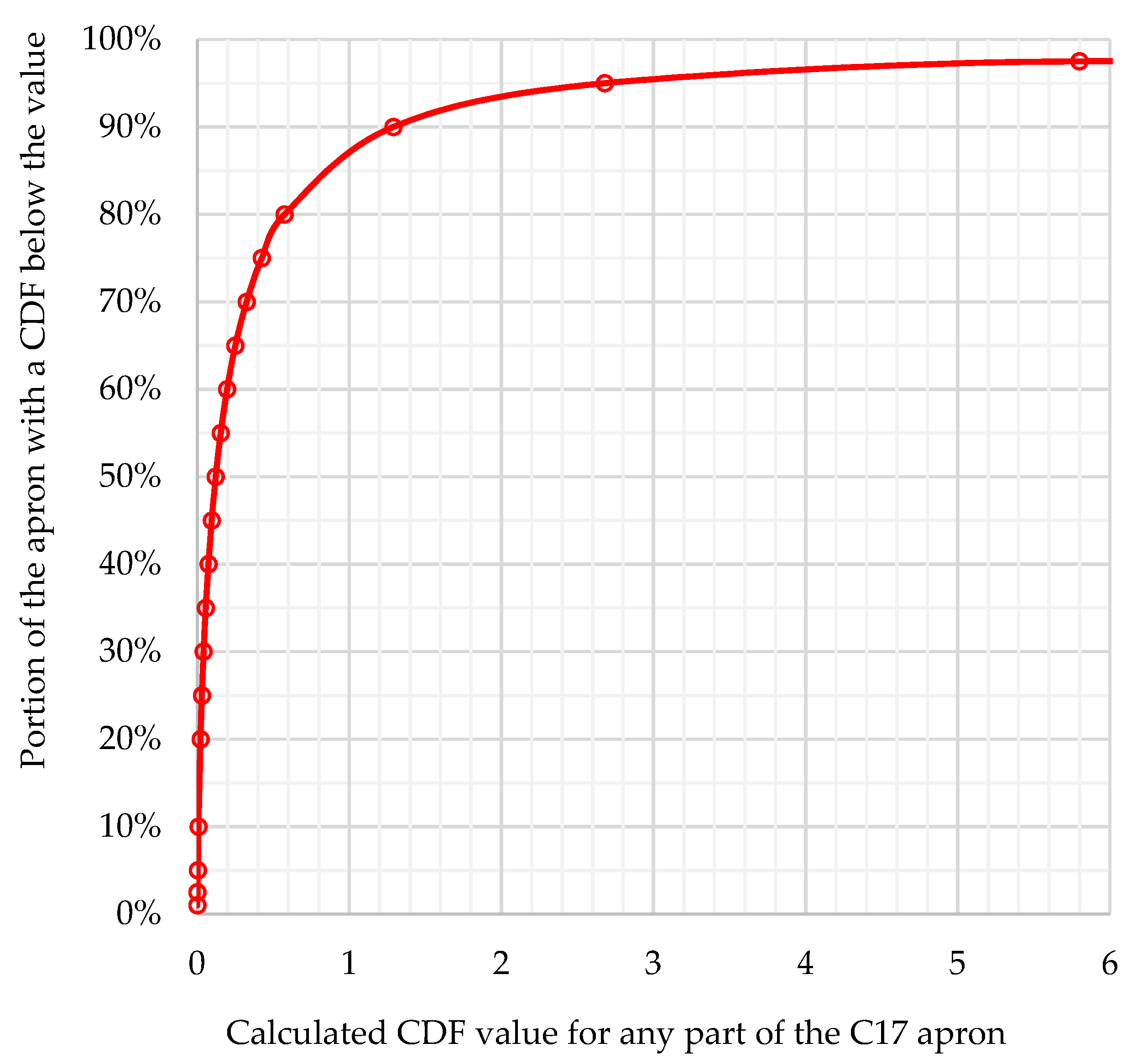
The Monte Carlo simulation required the random generation of statistically representative values for each of the four variable input parameters (Figure 4). The estimated CDF value for that combination of input parameter values was then calculated using the proxy model Equation (1). Each calculated CDF value was stored, and the process was repeated 100,000 times to provide a statistically correct set of 100,000 CDF values representing the variable strength of the as-constructed pavement. The results were presented as a cumulative probability distribution (Figure 6). The horizontal axis of Figure 6 was limited to a maximum value of 6 for ease of reading and because the rate of change was insignificant at higher CDF values.
The CDF values ranged from almost zero up to more than 100. This demonstrates the significant influence that concrete slab thickness, subgrade CBR, and concrete strength have on pavement strength, or in this case, on pavement life expressed as CDF. The median CDF value was 0.12. That is, 50% of the pavement had a predicted fatigue life that was at least 8.3 times higher than the 30-year design life. Furthermore, 87% of the CDF values had a CDF of 1.0 or lower, indicating that 87% of the pavement would not reach the failed condition of one or more full-depth structural cracks within the 30-year structural design life.

4.5. Comparing Design to Predicted Life

When modelled in FAARFIELD, the designed pavement thickness was found to have an effective design life of just one year based on the CDF of 29.1 compared to the 30-year design life. However, when the actual pavement thickness and the best estimate (average) values of the concrete flexural strength and the subgrade CBR were considered, FAARFIELD calculated a CDF value of 0.16. This indicates the actual fatigue life of the as-constructed pavement was more than 180 times longer than its effective design life. Furthermore, despite the design thickness being inadequate, when retrospectively analysed in FAARFIELD, the as-constructed pavement was almost adequate (CDF value of 1.4) and was not predicted to reach fatigue failure for decades after its design life was exceeded. This demonstrates the general tendency to construct aircraft pavements that are significantly stronger than required by pavement thickness design as well as the significant difference between pavement design life and pavement life prediction.
Based on the statistically correct distribution of pavement strength (expressed as CDF on Figure 6), the portion of the as-constructed pavement that was actually weaker than the designed pavement was approximately 1.5%: that is, the portion of the pavement with a CDF value greater than 29.1, as interpolated from the data used to generate Figure 6.
The deterministically predicted fatigue life of the as-constructed pavement was 47%, which is approximately 50%: that is, the portion of the pavement with a CDF value greater than 0.16, as interpolated from Figure 6. This indicates that the deterministic prediction of fatigue life was adequate and that routine Monte Carlo simulation is not required to predict pavement life because the best-estimate input value based on deterministic prediction also resulted in approximately 50% of the trafficked portion being expected to fail in fatigue based on the distribution of results from the Monte Carlo simulation.
The portion of the apron estimated to have a predicted fatigue life greater than the 30-year design life, indicated by a CDF of 1.0, was 87%. That is, the portion of the regularly trafficked portion of the apron predicted to reach the failed condition within the 30-year design life was just 13%. However, approximately 65% of the slabs are not regularly trafficked, and the failed condition is 50% of the slabs being cracked. Consequently, the predicted number of slabs with full-depth structural cracks within the 30-year design life was less than 3% of the total number of slabs. This is despite the fact that the pavement is significantly understrength when retrospectively analysed using FAARFIELD.
The stochastic analysis of the pavement strength to enable rigid aircraft pavement fatigue life prediction and the distribution of fatigue life indicators relies on robust data to represent the input parameter values for the various materials within the pavement. Although some parameters are robustly documented at a high frequency during construction, others are more challenging to define. For example, for the case study presented, there were 134 flexural concrete strength results available from the construction quality records. That provided a robust basis on which to consider the variable concrete flexural strength. However, extracting concrete samples from the apron slabs to measure the current strength is difficult without damaging the samples. In contrast to concrete flexural strength, the pavement design was based on only 13 soaked subgrade CBR values, which is a much less robust data set on which to characterise the post-construction subgrade bearing capacity. Similarly, the leanmix sub-base modulus was assumed to be adequately represented by the fixed value in FAARFIELD, which is not routinely verified during design or construction. Future research should consider forensic testing methods to extract representative samples of all of the relevant pavement materials to provide robust data on which to perform existing pavement structural life prediction.

5. Conclusions

Pavement thickness design does not predict pavement failure. Rather, it determines a reasonably economical combination of material layers and thicknesses that reduce the probability of the pavement reaching a failure condition to an acceptably low level. To predict the time until a pavement will reach failure, the failure condition must be understood, the chance of reaching failure implied by the design method must be defined, and a best estimate of the as-constructed pavement material properties and thicknesses must be considered. Based on the rigid aircraft pavement case study presented, it was concluded that aircraft pavements are generally constructed much stronger than they are designed and that aircraft pavement design is very conservative. As a result, even a theoretically understrength pavement has a low probability of ever reaching a structurally failed condition. This explains the general observation that rigid pavements generally exceed their structural design life and that most rigid aircraft pavements require rehabilitation due to serviceability failure rather than structural failure. Future research is recommended to extend this demonstration to include flexible aircraft pavements. The development of methods to efficiently determine reliable as-constructed pavement material and thickness properties is also required.

Funding

This research received no external funding.

Institutional Review Board Statement

Not applicable.

Informed Consent Statement

Not applicable.

Data Availability Statement

Not applicable.

Acknowledgments

This research was conducted under the umbrella of the University of the Sunshine Coast Airport Pavement Research Program, which is funded by the Australia airport industry and the Australian Department of Defence.

Conflicts of Interest

The author declares no conflict of interest.

References

  1. Federal Aviation Administration. Airport Pavement Design and Evaluation, AC 150/5320-6F; Federal Aviation Administration: Washington, DC, USA, 2016. [Google Scholar]
  2. Airfield Pavement Essentials, Airport Practice Note 12, Australia, Australian Airports Association. 2017. Available online: https://airports.asn.au/airport-practice-notes/ (accessed on 20 November 2021).
  3. White, G.; Kelly, G.; Fairweather, H.; Jamshidi, A. Theoretical socio-enviro-financial cost analysis of equivalent flexible aircraft pavement structures. In Proceedings of the 99th Annual Meeting of the Transportation Research Board, Washington, DC, USA, 12–16 January 2016. [Google Scholar]
  4. White, G.; Sterling, M.; Duggan, M.; Sterling, J. Sensitivity analysis of FAARFIELD rigid airport pavement thickness determination. In Proceedings of the 12th International Conference on Concrete Pavements, online event, 27 September–1 October 2021. [Google Scholar]
  5. Federal Aviation Administration. Calibration of FAARFIELD Rigid Pavement Design Procedure; Final Report DOT/FAA/AR-09/57; Federal Aviation Administration: Washington, DC, USA, 2010. [Google Scholar]
  6. Jamieson, S.; White, G. Defining Australian rigid aircraft pavement design and detailing practice. In Proceedings of the International Airfield and Highway Pavement Conference, online event, 8–10 June 2021. [Google Scholar]
  7. Huang, Y.H. Pavement Analysis and Design; Prentice-Hall: Englewood Cliffs, NJ, USA, 1993. [Google Scholar]
  8. Federal Aviation Administration. Airport Pavement Design and Evaluation; Advisory Circular 150/5320/6E (superseded on 10 November 2016); Federal Aviation Administration: Washington, DC, USA, 2009. [Google Scholar]
  9. Brill, D.; Kawa, I. Relative performance of CC6 concrete pavement test items at the FAA national airport pavement test facility. In Proceedings of the FAA Worldwide Airport Pavement Technology Transfer Conference, Galloway, NJ, USA, 5–7 August 2014. [Google Scholar]
  10. Brill, D.; Kawa, I. Advances in FAA Pavement Thickness Design Software: FAARFIELD 1.41. In Proceedings of the ASCE International Airfield & Highway Pavements Conference, Chicago, IL, USA, 27–30 August 2017. [Google Scholar]
  11. White, G.; Balestra, R. Comparing rigid and flexible airport pavement thicknesses designed by different methods. In Proceedings of the International Airfield and Highway Pavements Conference, Chicago, IL, USA, 21–24 July 2019. [Google Scholar]
  12. FAARFIELD, Version 1.42; Federal Aviation Administration: Washington, DC, USA, 18 September 2017. Available online: https://www.airporttech.tc.faa.gov/Products/Airport-Safety-Papers-Publications/Airport-Safety-Detail/ArtMID/3682/ArticleID/4/FAARFIELD-142 (accessed on 20 November 2021).
  13. FAARFIELD 2.0; Federal Aviation Administration: Washington, DC, USA, 22 June 2020. Available online: https://www.airporttech.tc.faa.gov/Products/Airport-Safety-Papers-Publications/Airport-Safety-Detail/ArtMID/3682/ArticleID/2841/FAARFIELD-20 (accessed on 20 November 2021).
  14. Signoret, J.-P.; Leroy, A. Monte Carlo Simulation. In Reliability Assessment of Safety and Production Systems; Springer: Cham, Switzerland, 2021; pp. 547–586. [Google Scholar]
  15. Ross, S.M. Simulation, 2nd ed.; Academic Press: Cambridge, MA, USA, 1997. [Google Scholar]
  16. White, G. A probabilistic approach to flexible aircraft pavement thickness determination. In Proceedings of the 8th International Bearing Capacity of Road, Railways and Airfields Conference, Champaign, IL, USA, 29 June–2 July 2009; pp. 889–895. [Google Scholar]
  17. Cromhout, A.; Horak, E.; Olivier, P. Impact of probability density function on indicators relating to pavement performance for flexible pavement structures. In Proceedings of the 12th Conference on Asphalt Pavements for Southern Africa, Sun City, South Africa, 13–16 October 2019; pp. 806–821. [Google Scholar]
  18. White, G. Stochastic strength rating of flexible airport pavements using construction data. Int. J. Pavement Eng. 2020, 21, 537–548. [Google Scholar] [CrossRef]
  19. White, G.; Lourenco, R.; Low, J. Stochastic post-construction strength rating of the new runway at Sunshine Coast Airport. In Proceedings of the International Airfield and Highway Pavement Conference, online event, 8–10 June 2021. [Google Scholar]
  20. @Risk for Risk Analysis; Palisade: Ithaca, NY, USA, 2020; Available online: https://www.palisade.com/risk/ (accessed on 20 October 2020).
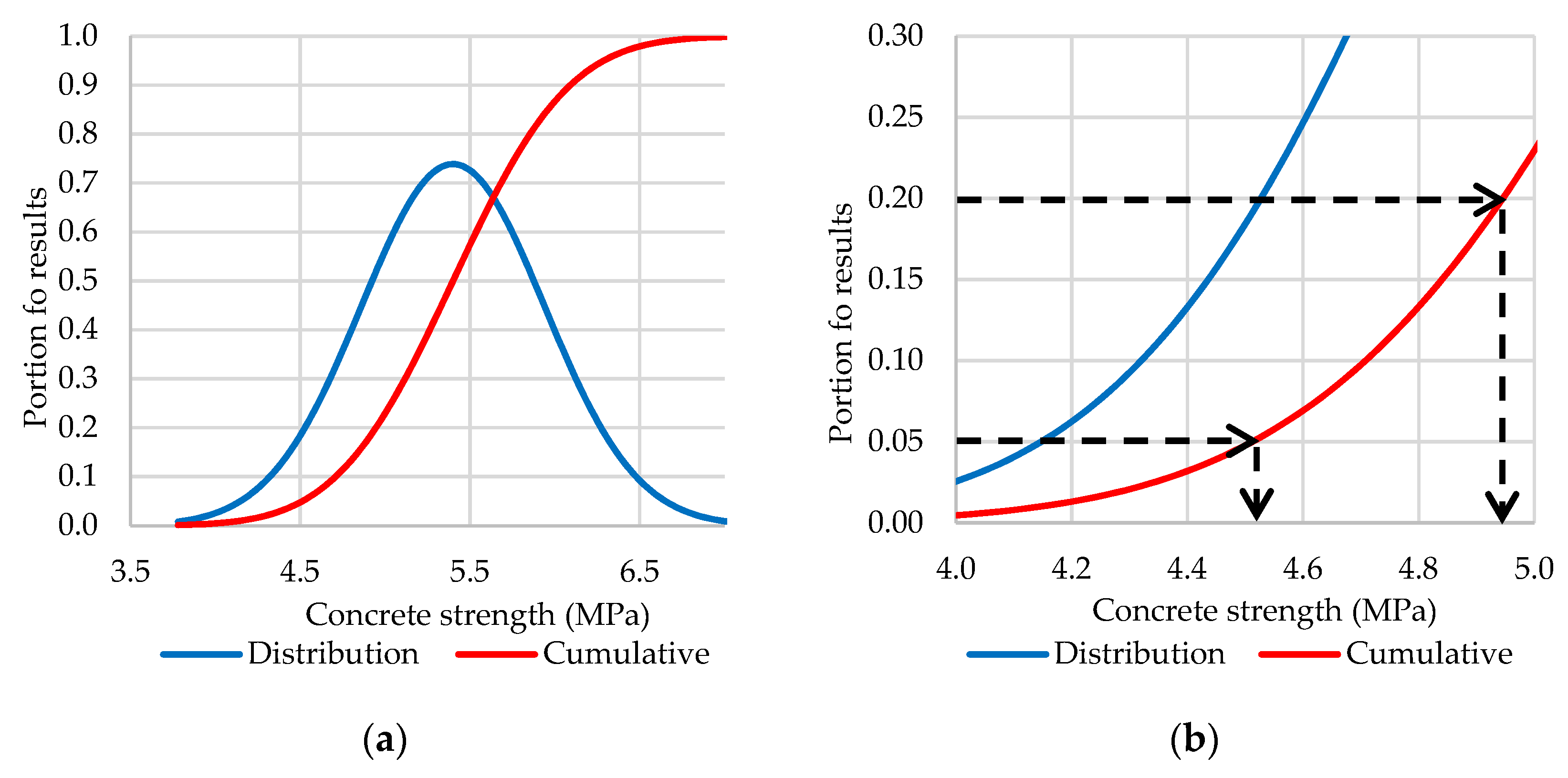
Figure 1. Comparison of USA to Australian characteristic concrete strength for (a) the full population of results and (b) showing the 95%-ile (0.05) and 80%-ile (0.20) strength for the same population.
Designs 06 00012 g001
Figure 2. Example of SCI reduction with aircraft load applications, adapted from [9].
Designs 06 00012 g002
Figure 3. Example of best-fit regression failure through test section performance data, adapted from [5].
Designs 06 00012 g003
Figure 4. Variable input parameter models from @RISK. (a) Subgrade CBR; (b) concrete flexural strength; (c) concrete thickness; (d) leanmix sub-base thickness.
Designs 06 00012 g004
Figure 5. Calculated (actual) and proxy model (estimated) CDF values.
Designs 06 00012 g005
Figure 6. Cumulative probability of CDF from Monte Carlo simulation.
Designs 06 00012 g006
Table 1. Stochastic rigid FAARFIELD input parameters and basis.
ParameterUnitsPercentile Basis of Characteristic ValueReference
Subgrade modulusMPa85%-ile value[1]
Concrete flexural strengthMPa80%-ile value in the USA
95%-ile value in Australia
[2]
Table 2. Design aircraft traffic.
AircraftMassAnnual DeparturesDesign Departures
KC-30B233 t1044056
C-17A266 t1044056
C-5349 t5195
C-13080 t52020,280
Note: The KC-30B is a military version of an A330 airframe and was modelled as an A330-200.
Table 3. Summary of variable input parameter values.
StatisticSubgrade CBR (%)Concrete Slab Thickness (mm)Leanmix Sub-Base Thickness (mm)Concrete Strength (MPa)
Number of results131010134
Minimum1.54051504.8
Average2.354171605.8
Standard deviation0.885.38.04.2
Maximum4.54201756.9
Table 4. Summary of designed pavement thickness.
Input ParameterDesigned PavementFAARFIELD Designed Pavement
ValueBasisValueBasis
Subgrade CBR (%)1.585%-ile from design investigation1.585%-ile from design investigation
Concrete thickness (mm)400Designed thickness460FAARFIELD calculated thickness for CDF 1.0
Leanmix thickness (mm)150Designed thickness150Designed thickness
Concrete strength (MPa)4.9Corrected 95%-ile design value to be4.9Corrected 95%-ile design value to be
Calculated CDF29.1-1.0-
Table 5. Summary of as-constructed pavement thickness.
Input ParameterAs-Constructed Design ParametersAs-Constructed Parameters
ValueBasisValueBasis
Subgrade CBR (%)1.585%-ile from design investigation2.3Average (50%-ile) from investigation
Concrete thickness (mm)415Average of as-constructed thicknesses415Average of as-constructed thicknesses
Leanmix thickness (mm)160Average of as-constructed thicknesses160Average of as-constructed thicknesses
Concrete strength (MPa)5.580%-ile value from as-constructed records5.7Average from as-constructed records
Calculated CDF1.38-0.16-
Note: CBR 2.3 was entered into FAARFIELD as 20 MPa.
Table 6. Design aircraft traffic.
FactorReferred to as:LevelsNumber of Levels
Subgrade CBR (%)SG_CBR1, 2, 3, 44
Concrete strength (MPa)Flex_Str4.2, 4.7, 5.2, 5.7, 6.25
Leanmix thickness (mm)LMC_Thick400, 410, 4203
Slab thickness (mm)PCC_Thick 150, 160, 170, 1804
Publisher’s Note: MDPI stays neutral with regard to jurisdictional claims in published maps and institutional affiliations.