1. Introduction
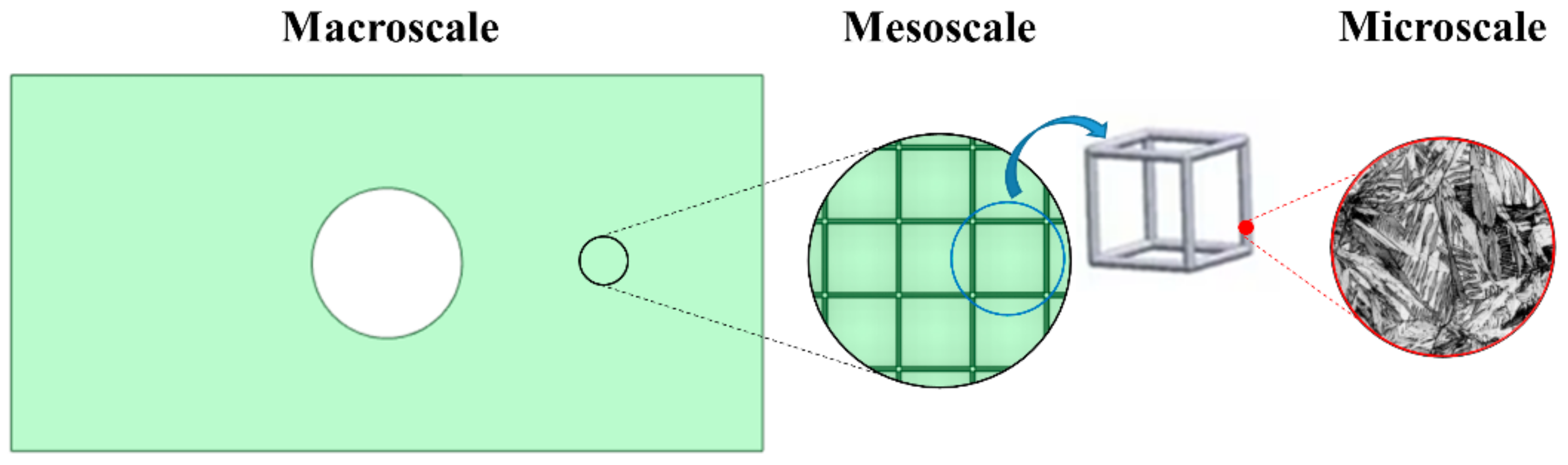
In the literature, the structure of a component can be categorized with respect to its physical size, from bigger to smaller, and to macro-, meso-, and microscale structures [
1]. However, there are no specific size limits that separate one from the other. The macroscale is considered the external layout of a structure, while its infill is the mesoscale structure. The elements that constitute the infill are usually unit cells creating a periodically ordered pattern [
2]. The structure of the unit cells is a good example of a microscale structure. According to the theory of composite materials, a unit cell is the smallest volume that can be measured to give a representative value of the entire structure [
3,
4]. Hence, it is assumed that the continuum mechanics can be applied to the macro-, meso-, and microscale levels of a structure [
1].
Figure 1 shows the three structure levels of a hollow plate where its mesoscale structure consists of uniform cubic cells.
It is very common to use cellular structures inside the components to reduce their weight or affect their physical and mechanical properties [
7]. The cellular structures can be classified into foams, honeycombs, and lattice structures [
8]. The foams can be either open or closed and are randomly generated [
9]. Mesoscale structures of bones and shells are two characteristic examples of foams. Honeycombs are cellular designs consisting of unit cells such as hexagons with regular shape and size. They usually are two-dimensional designs that can be extruded in the third direction. Finally, lattice structures are three-dimensional unit cells, such as cubic and octahedral unit cells, arranged periodically, composing a porous material structure of interconnected struts and nodes [
2]. An advantage of the lattice structures compared to foams and honeycombs is that they are flexible designs that can be easily optimized to satisfy specific requirements. The desired material property of a lattice structure can be achieved by changing the size, the orientation, the struts, and the nodes of its cells [
10]. Many researchers agree that the lattice structures outperform foam and honeycomb cells due to their high stiffness, strength, energy absorption, heat dissipation, and damping [
2,
11]. Due to their good mechanical properties, they can be widely applied in various industries such as the aerospace, automotive, and biomedical industries [
12].
According to Bendsøe [
13], structural optimization (SO) can be classified into shape, size, and topology optimization. The topology of a design can be optimized in any of its levels, i.e., at the macro-, meso-, and microscale levels, using different optimization methods [
14]. The solid isotropic material with penalization (SIMP) [
13,
15], the level set [
16], the bi-directional evolutionary structural optimization (BESO) [
17], the smooth-edged material distribution for optimizing topology (SEMDOT) [
18], and the floating projection topology optimization (FPTO) [
19] are some notable methods for the optimization of the macroscale. On the other hand, the homogenization-based topology optimization (HMTO) and the size gradient method (SGM) are two popular methods for the optimization of the mesoscale. Finally, the aforementioned methods can be easily adapted on a microscale level [
1].
There are plenty of research papers about TO, either on the macroscale or mesoscale level. In addition, many works deal with the concurrent multiscale optimization [
20]. Watts et al. [
21] modified Sigmund’s 99-line Matlab code [
22] to solve a three-dimensional, multiscale compliance problem via polynomial interpolation of stiffness tensors. The coating approach combined with the compliance TO by Clausen et al. [
23] resulted in designs with improved buckling load. Kato et al. [
24] proposed a micro–macro concurrent TO for nonlinear solids with a multiscale decoupling analysis. Hoang et al. [
25] presented a direct multiscale TO approach without material homogenization at the microscale but using adaptive geometric components instead. Liu, Chan, and Huang [
5] developed a concurrent two-scale TO algorithm based on the BESO method for maximizing the natural frequency of structures. White et al. [
26] developed a multiscale TO using neural network surrogate models for spatially varying lattices. Despite the fact that there are some approaches of multiscale TO, its practical application is in its beginning since there is not a commercial program that implements it automatically.
In this research paper, a two-scale TO was conducted in ANSYS software utilizing manually the homogenization theory at both the macro- and mesoscale levels. The applied algorithms for the macro- and mesoscale optimization were the traditional compliance SIMP and the HMTO, respectively. Through the current study, the authors answer the following research questions: What is gained by the existence and optimization of the mesoscale structure? How should a combined macro- and mesoscale TO be practically performed? For this reason, a case study of the notable jet engine bracket from General Electric (GE bracket) was used [
27]. Five different optimization workflows (mentioned as optimization methods) of the GE bracket were implemented, trying to determine the most efficient method in terms of structural strength. In addition, the impact of the type and the orientation of the cells in the mesoscale structure were explored. Finally, the lightest design solution was identified and presented among these workflows.
The structure of the rest of the paper is as follows: in
Section 2, the theoretical background of the used approaches for the topology optimization of both macroscale and mesoscale is introduced. In
Section 3, the implemented methodology is presented in detail. The findings in this research work are displayed in
Section 4 and discussed thoroughly in
Section 5. Finally,
Section 6 and
Section 7 encompass the conclusion and the possible future research, respectively.
2. The Structural Optimization Problem for Macro- and Mesoscale Structures
The optimization of the macroscale structure can be described by the general SO problem as it was presented by Bendsøe [
13]. The SO problem is broadly known in its translation to a standard minimum compliance problem with a volume constraint. The following discretized problem is based on the homogenization theory and the interpolation method of SIMP [
28]:
where
c: compliance;
ρ: material density;
U: global displacement;
g: volume constraint;
: element density;
: element volume’
: maximum allowed volume (volume of the design space);
K: global stiffness matrix;
F: external loading vector;
E: overall structure elasticity;
p: penalization factor;
: Young’s modulus.
For the current optimization problem, Equation (1) is the defined objective function, which in this case corresponds to the compliance of the structure. Furthermore, there are four constraints in this minimum compliance problem. The first constraint, Equation (2), is the total design volume whose value should be equal to or less than the volume of the design space. The constraints denoted by (Equation (3)) represent other possible behavioral and design constraints. At the third constraint, Equation (4), the values of the element density are bounded between zero and one, where the former represents void and the latter represents material. The fourth constraint, Equation (5), is the equilibrium equation, which is further described by the elastic scaling law (Equation (6)).
According to Pan, Han, and Lu [
2], the cellular shape and size of the mesoscale structure, and thus the lattice structure, can be either uniform or nonuniform. On the one hand, the design and optimization of uniform lattice structures can be conducted by three different design approaches: (1) computer-aided design (CAD), (2) design based on mathematical algorithms, and (3) design based on TO. On the other hand, the design and optimization of the nonuniform lattice structures can be conducted either by functional gradient design or by SO [
2]. The SGM [
29] and the HMTO [
30] are two notable approaches in each of these cases. The HMTO is applied in this paper.
For the HMTO, variable-density cellular structures are used in the creation of the mesoscale structure. This method uses the homogenization theory to obtain the real mechanical properties of the infill as a function of the relative density of its lattice cells [
4,
31]. In general, the cellular structure has anisotropic behavior. In the HMTO method, the following scaling law describes this behavior [
30]:
where the stress,
; the strain,
; and the elasticity,
can be written in matrix form:
The
and
are the scalar components of the stress and strain, respectively. The homogenization method utilizes the micromechanics theory, where the FEA results of one unit cell with different relative densities are used to predict the behavior of the entire mesoscale structure. The scaling law of structure’s elasticity can be described by the polynomial function with the best fit of the computational data between the elastic constants and the arbitrary relative densities of the cell [
30]. A general form of this polynomial is the following:
This polynomial represents the real mechanical properties of the mesoscale as a function of the relative density
[
4]. For the optimization of the mesoscale structure, a similar formulation to the SO problem is applied:
Here the derived intermediate elements from the SIMP method are replaced by cells with corresponding densities creating a graded lattice structure [
30]. In addition, the polynomial scaling law, Equation (14), replaces the fictitious elastic scaling law (Equation (6)) of the SIMP method. Analytical calculations for the TO of both the macroscale and mesoscale are omitted for brevity. Interested readers should be referred to the research works of Bendsøe and Sigmund [
28,
32] and Cheng, Zhang, Biyikli, Bai, Robbins, and To [
30].
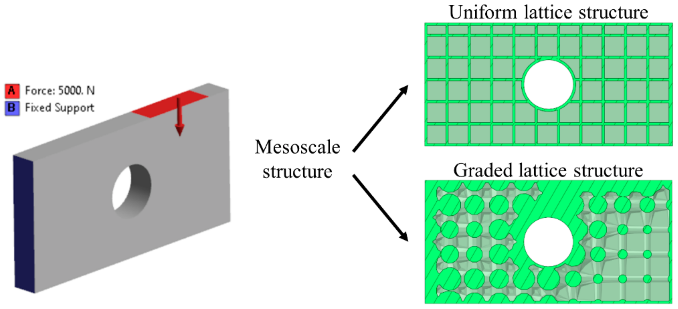
Figure 2 presents an example of the HMTO method of a hollow cantilever plate. The hollow plate is fixed on its right face, and a 5000 N vertical force is applied on its top face. In the first case, uniform cubic cells were used for its mesoscale structure, while the HMTO method was implemented in the second case resulting in an infill with a graded cubic structure.
The authors use the term lattice optimization (LO) when they refer to the HMTO method. Both the described SIMP and LO methods are applied for the optimization of the macro and mesoscale structure, respectively, in this research work.
3. Methodology
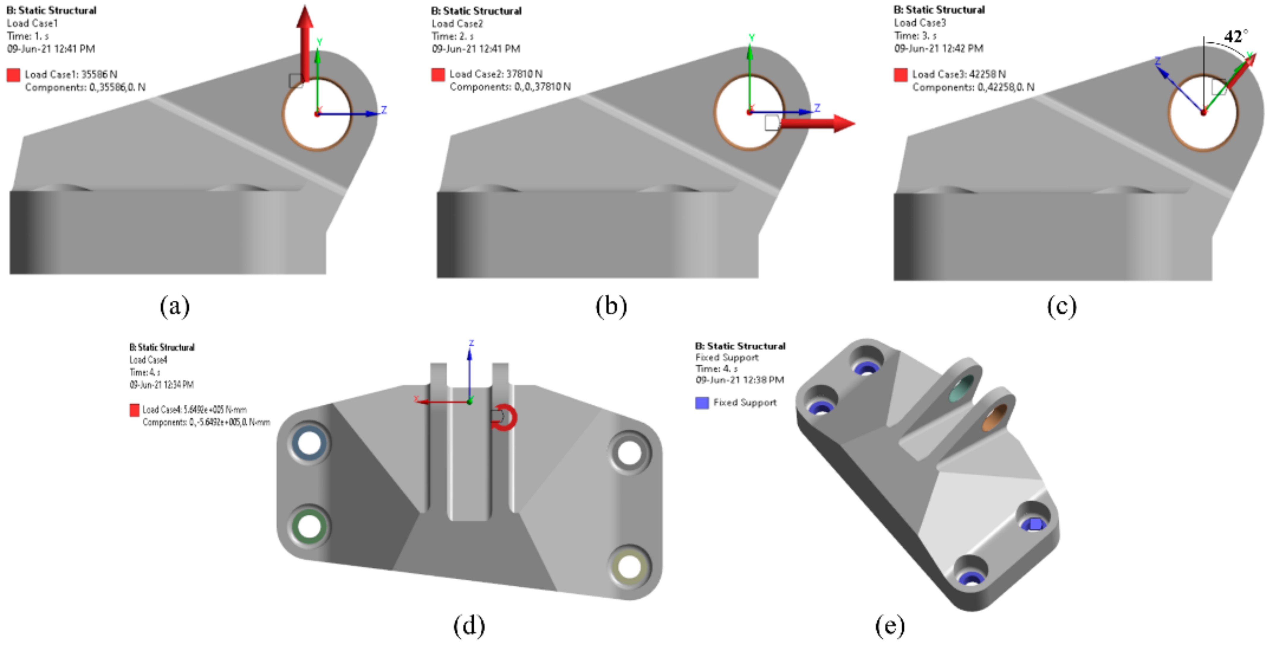
The presented case study in this paper is the known jet engine bracket by General Electric, also called the GE bracket. This model was used by General Electric as a design challenge in 2013 [
27]. The participants in this challenge were asked to reduce the weight of an existing aircraft engine bracket without compromising its strength. There were 629 entries, and the winner could reduce the initial weight of the bracket from 2.033 Kg to 327 g, which corresponds to nearly 84% weight reduction. The authors decided to use this GE bracket as a case study in this paper due to its popularity and its known load cases and boundary conditions. The given load cases were the following:
Load case 1 (LC1): a vertical static linear load of 35,586 N;
Load case 2 (LC2): a horizontal static linear load of 37,810 N;
Load case 3 (LC3): a static linear load 42,258 N, 42 degrees from vertical;
Load case 4 (LC4): a static torsional load of 564,924 Nmm horizontal at the intersection of the centerline of the pin and the midpoint between the clevis arms.
The bracket was fixed with four bolts, and a 19.05 mm diameter pin was placed between the clevis. Both the load cases and the boundary conditions are illustrated in
Figure 3.
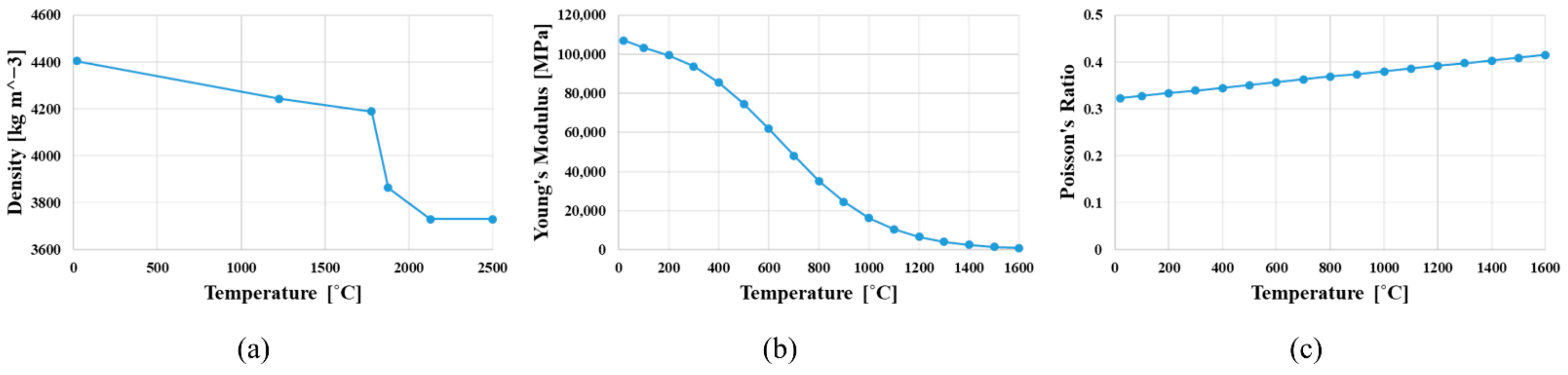
The applied material was Ti-6Al-4V with 903 MPa yield strength. Its density, Young’s modulus and, Poisson’s ratio versus temperature are depicted in
Figure 4.
The CAD model of the GE bracket was given by General Electric in an IGES file format and was downloaded from the company’s homepage. This model was used as a reference model and was imported to ANSYS software for FEA, TO, and numerical validation. The FEA of the GE bracket was conducted in ANSYS Mechanical. The same software was also used for both TO and LO. According to the challenge, the intended production method was additive manufacturing (AM). Thus, the optimized designs were not redesigned but instead were prepared for 3D printing in ANSYS SpaceClaim. In addition, ANSYS SpaceClaim was used for the creation of the uniform mesoscale structure. Finally, the numerical validation studies were implemented in ANSYS Mechanical, where only the designs with an FOS > 1 (Factor of Safety) against yield were accepted. The used finite elements in all simulations were 3 mm tetrahedrons. The chosen size of the elements was decided after a convergence study conducted in ANSYS Mechanical.
3.1. Optimization of the Macroscale
The macroscale structure of the GE bracket was optimized using TO. The applied method was SIMP with compliance and minimization of mass as objective function and response constraint, respectively. Firstly, the GE bracket was topologically optimized for each of the four load cases separately and then for all of them together. The authors’ intention was two-fold. On the one hand, we wanted to show the sensitivity of the TO-results to the load changes. On the other hand, we wanted to manually identify the worst load case, which in this case study was LC4. An implementation of a p-norm or related soft-max function could automatically identify the worst-case scenario via the calculation of maximum displacement due to random combinations of the given load cases. The best design solutions in terms of weight were identified and further tested for their strength in validation studies.
3.2. Combining the Macro- and Mesoscale Optimization
At this point, a lattice infill was added inside the structure. The applied cell structure was a 12 mm cubic cell oriented in the z direction. Designs with either uniform or variable-density lattice infill were used. The LO method presented in
Section 2 was used for the optimization of the mesoscale structure. Five different optimization workflows were conducted for a 50% weight reduction. The load cases were gradually added to the TO of the bracket. The authors intended to compare the derived design solutions by different optimization combinations at the same weight, as well as observe the change in the designs by adding load cases. The used optimization methods in this research paper were the following:
Lattice: Initial layout with uniform lattice infill;
LO: Topology optimization of the mesoscale with variable-density lattice infill;
TO: Topology optimization of the macroscale;
TO_Lattice: Topology optimization of the macroscale and uniform lattice infill;
TO_LO: Topology optimization of the macroscale and topology optimization of the mesoscale with variable-density lattice structure.
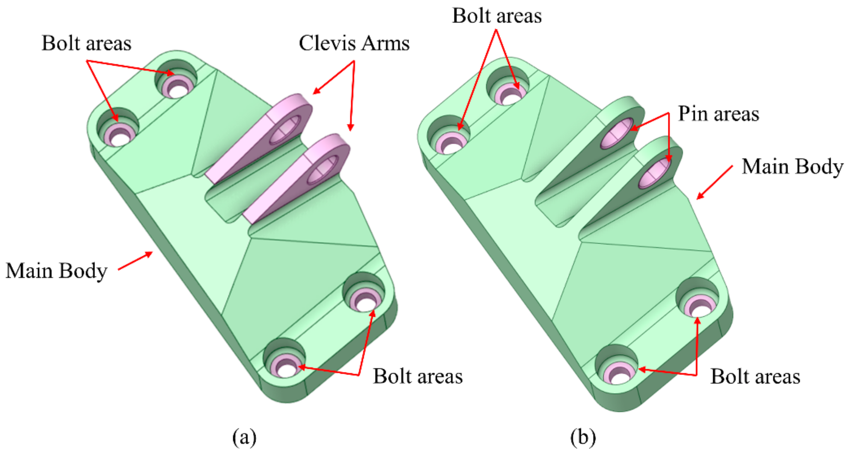
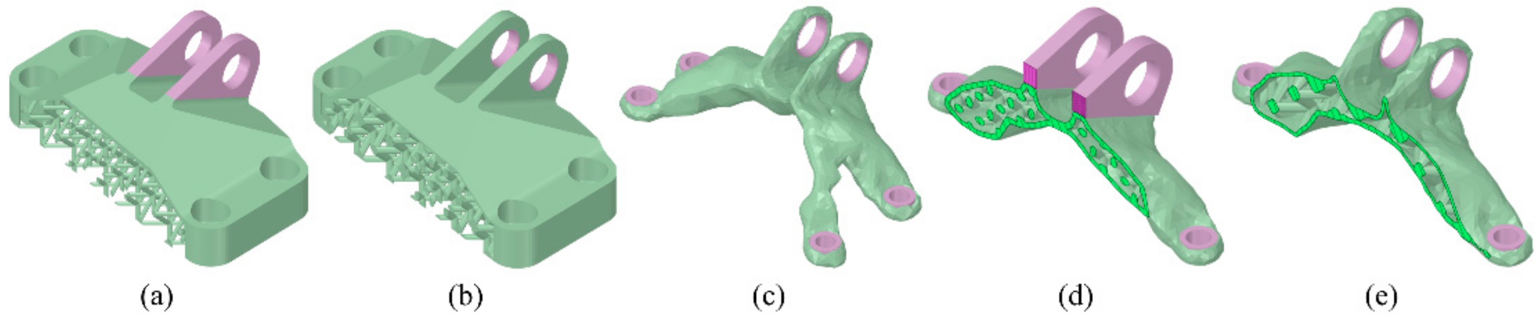
On the one hand, a multibody part was created based on the original IGES file of the GE bracket for the Lattice and the TO_Lattice methods. This part consisted of the main body, the bolt areas, and the clevis arms. Bonded contacts were applied between the bodies. Both the lattice infill and the TO density were limited to the main body, while the bolt areas and the clevis arms were used for the application of the boundary conditions and the load cases, respectively. Hence, in the Lattice method, the clevis arms and bolt areas were 100% solid, while in the TO_Lattice, they were used as ‘frozen area’ for the TO. On the other hand, for the remaining three methods, LO, TO, and TO_LO, a similar multibody part was used, but in this case, pin areas were created instead of the whole clevis arms. The two different multibody parts are shown in
Figure 5.
3.3. In the Pursuit of the Best Design Solution in Terms of Weight
The same optimization methodologies were implemented in the identification of the lightest design solutions with FOS>1. However, a preliminary research of the cell type and orientation was conducted. Three different lattice cells were checked with the same criteria in the x, y, and z orientation. These were the cubic, the octahedral, and the octet. A 6 mm internal thickness was used for the bracket. In addition, the applied strut thickness in each cell was 4 mm, while the cell size was chosen in a way that all three infills could result in a 50% weight reduction. Hence, 12, 16, and 24 mm cell sizes were used in the cubic, octahedral, and octet cells, respectively. The lattice cell, as well as its orientation with the best FOS, was used in the Lattice, LO, and TO_Lattice, and TO_LO methods. The lightest design was identified among the five implemented methods for the load cases applied simultaneously. The results for FEA, optimizations, and validation studies are presented in the next section.
4. Results
As described in the methodology, a TO of the bracket’s macroscale structure was conducted in the first step for independent and combined load cases. The design solutions were compared for maximum weight reduction. In the second step, multiscale optimizations, combining macro and/or mesoscale optimization, were carried out using the Lattice, LO, TO, TO_Lattice, and TO_LO methods for 50% weight reduction and gradually added load cases. A research study of the cubic cell type (cubic, octahedral, and octet) and cell orientation was conducted in the third step. Finally, the identified cell type, including its orientation with the best solution, was adapted to the optimization methods for the creation of the lightest design solutions.
4.1. FEA of the GE Bracket
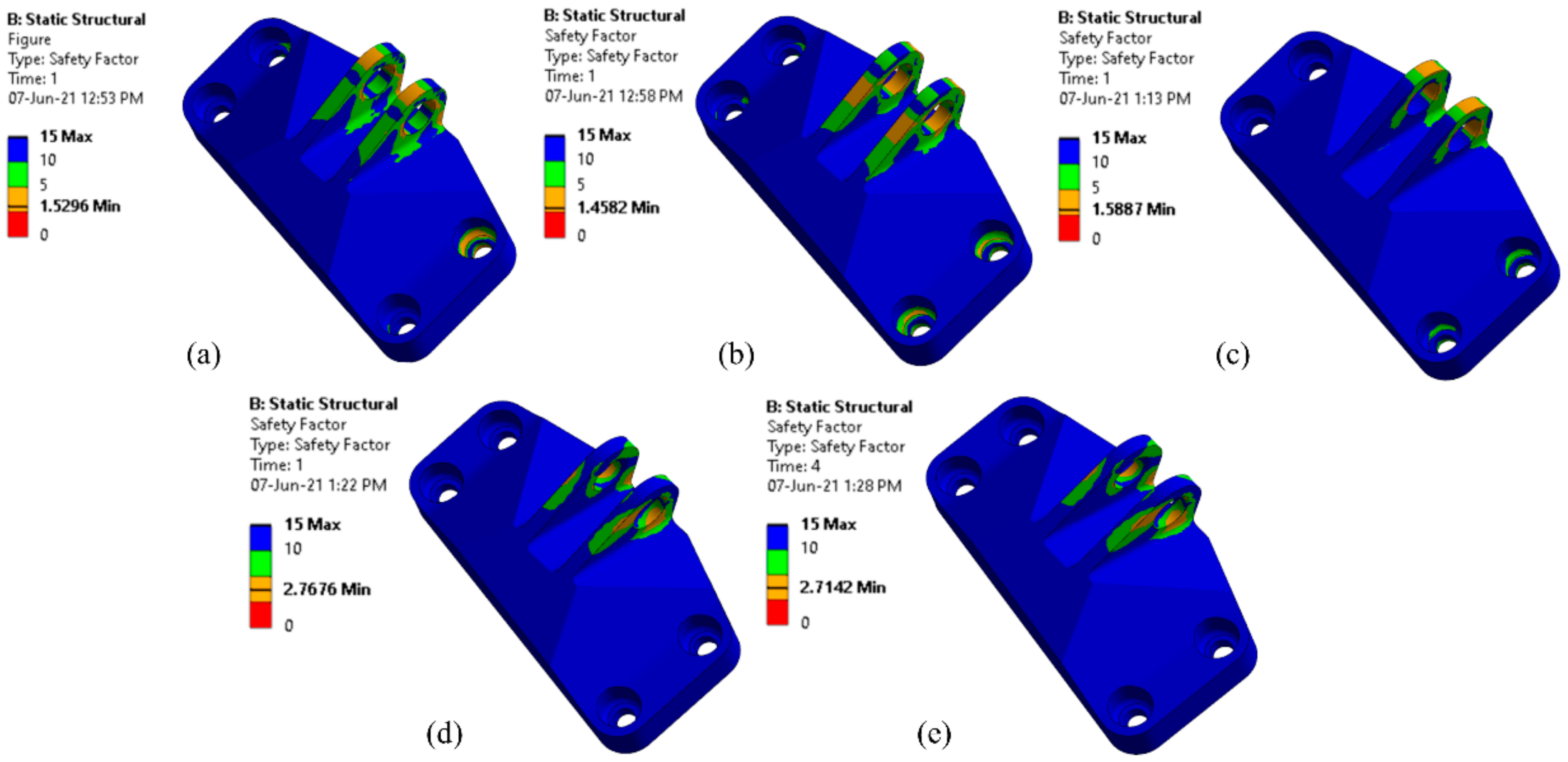
The FEA of the GE bracket was conducted before the optimization of the design. The maximum von Mises stress as well as the FOS against yield were determined in each load case and in the case of the combined load cases (LC1234). The results are shown in
Figure 6. The horizontal static linear load (LC2) and the static torsional load (LC4) resulted in the lowest (1.46) and the highest (2.77) FOS, respectively. The FOS of the combined load cases was 2.71, which is close to the result of the LC4. It seems that the load path created by the static torsional load dominates the load paths by created the other three load cases. In addition, all the results of the FOS were higher than one, showing that there was place for optimization.
The maximum von Mises stress, the minimum FOS against yield, and the simulation time of the FEA of the GE bracket are summarized in
Table 1.
4.2. Exploring the Different Load Cases
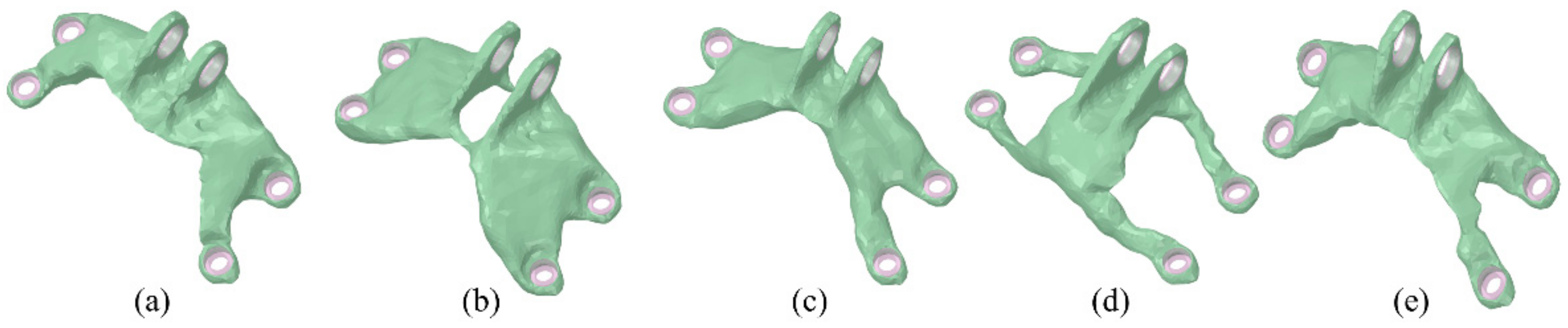
The design solutions from the TO of the GE bracket’s macroscale structure in each of the LC and in all of them combined are shown in
Figure 7. In addition,
Table 2 presents the results of the weight, maximum von Mises stress, FOS against yield, and simulation time in each case.
As it is observed in
Figure 7, each load case led to a completely different design solution. The initial weight of the GE bracket was 2.033 Kg. The best solution in terms of weight was achieved in the LC4 with a 76.7% weight reduction (475 g). The optimized design for all load cases (LC1234) gave a solution with a slightly higher weight (492 g). Furthermore, the design solutions presented in
Figure 7 show the sensitivity of the TO. An eventual change either in the load cases or the boundary conditions could lead to a completely different design.
4.3. Identification of the Best Optimization Method
The next step was the optimization of the GE bracket with the implementation of the five optimization methods presented thoroughly in
Section 3: (1) Lattice, (2) LO, (3) TO, (4) TO_Lattice, and (5) TO_LO. The optimization goal in all methods was the reduction of the bracket’s weight by 50%. The GE bracket was optimized, while the four LCs were gradually added in each optimization method. Thus, 20 simulations were conducted at this point.
Figure 8 depicts the derived design solutions in the case where all the LCs were applied.
Table 3 presents the results of the minimum FOS against yield from the validation studies in each case.
The Lattice method with the use of uniform lattice infill resulted in the lowest FOS among all the optimization methods. Both LO and TO with the optimization of the mesoscale with variable-density lattice infill and the optimization of the macroscale, respectively, had similar results. The fourth method (TO_Lattice) with the optimization of the macroscale and the uniform lattice infill outperformed the previous methods. Finally, the TO_LO with both the optimization of the macro- and mesoscale resulted in stiffer solutions in each case. It seems that the use and the optimization of the infill in the topologically optimized layout of the bracket strengthen its structure.
4.4. A Preliminary Research of the Cell Type and Orientation
The results of the preliminary research for the cell type and orientation of the bracket’s infill are presented in this section.
4.4.1. Cell Type
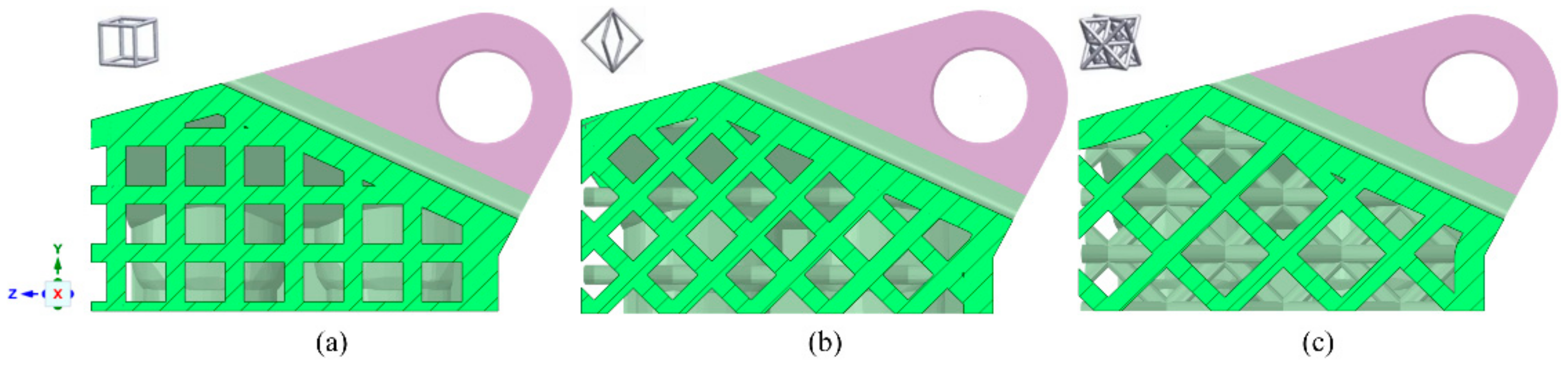
The first step in this preliminary research was the optimization of the GE bracket using three different cell types: 12 mm cubic, 16 mm octahedral, and 24 mm octet for its uniform lattice infill. The Lattice method was also conducted here with a 50% weight reduction. A section view of each design is depicted in
Figure 9.
4.4.2. Cell Orientation
In addition, the orientation of the bracket was changed from z to both x and y, resulting in the different orientations of the lattices. Hence, nine optimizations were carried out in total. The octet infill in the z orientation gave the highest FOS (2.54).
Figure 10 shows the uniform octet infill of the bracket in the three orientations. In addition,
Table 4 presents the results of the validation studies.
4.5. The Best Design Solutions in Terms of Weight
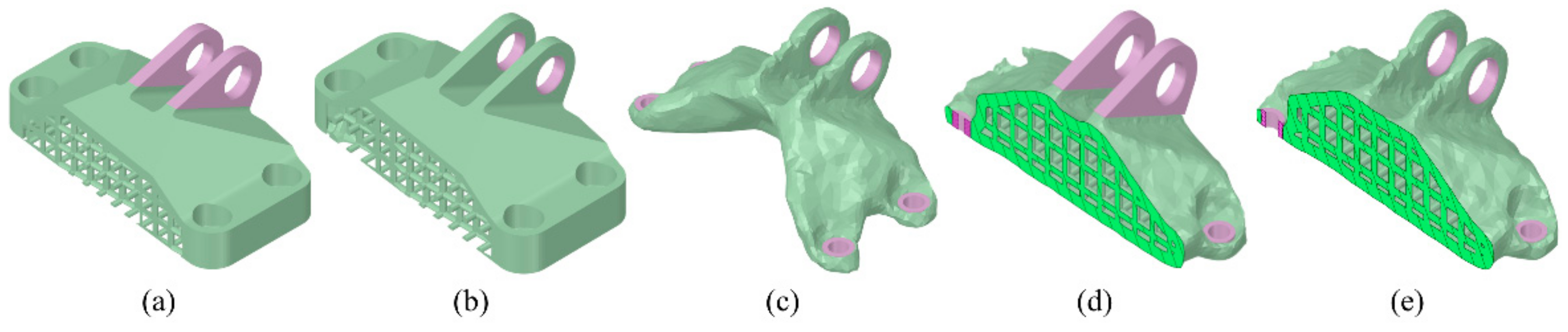
The identified cell type and its orientation from the previous section (24 mm octet with z orientation) was used for the infill in the Lattice, LO, TO_Lattice, and TO_LO optimization methods.
Figure 11 and
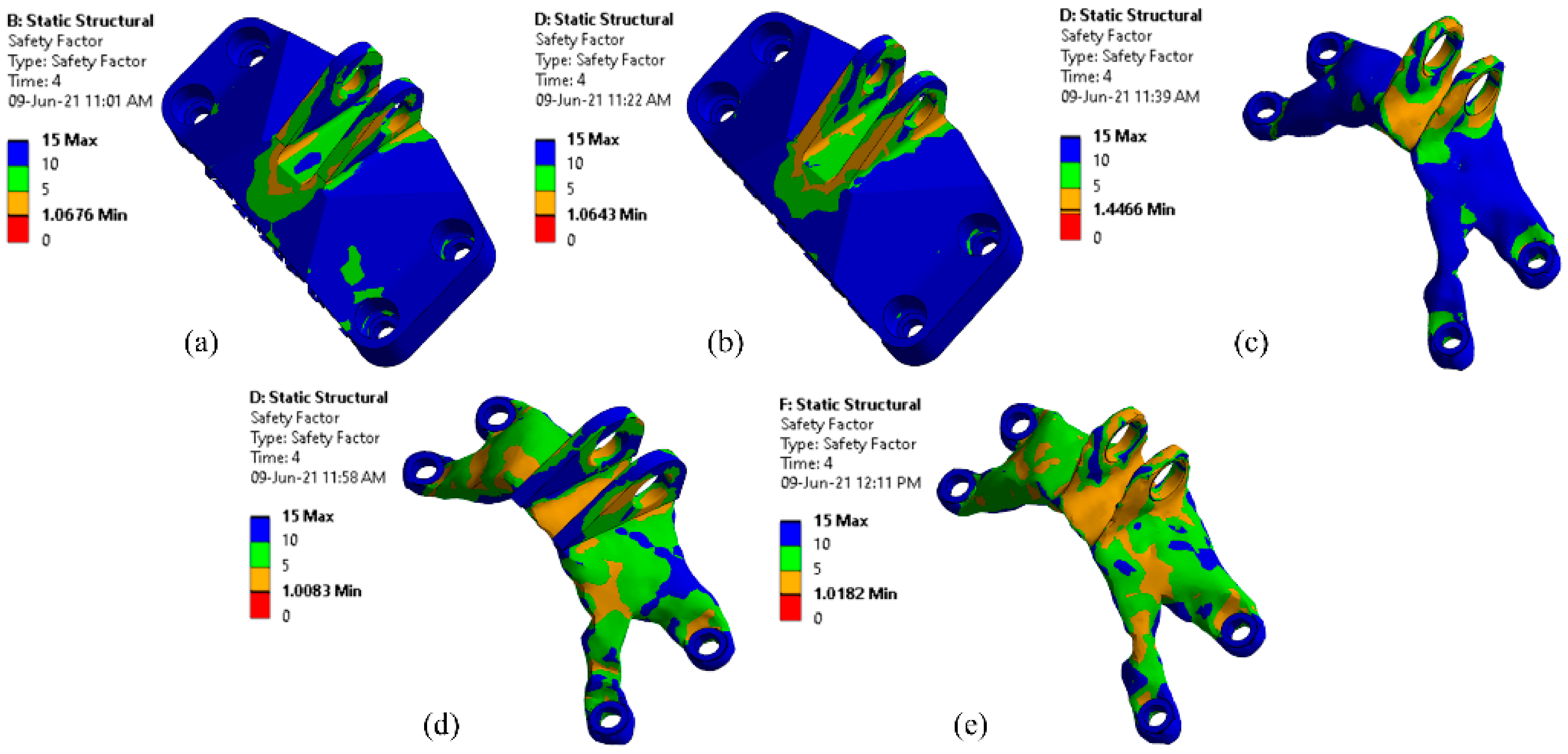
Figure 12 show the best design solutions and their FOS plots, respectively, in each method.
The analytical results of the simulations are presented in
Table 5. Both TO_Lattice and TO_LO gave design solutions that were lighter than the winner of the challenge in 2013 (327 g). The TO_LO gave the best solution with only 290 g, which corresponds to an 85.8% reduction of the initial weight of the GE bracket. It seems that both the use of uniform lattice structure and the optimization of it with LO could give better design solutions. However, the TO gave the quickest optimized design with a 1.04 g/sec weight reduction ratio. Hence, when the optimization goal is the biggest weight reduction, both TO_Lattice and TO_LO are suggested, with the former resulting in a quicker design solution. On the other hand, the TO is the best option when a designer wants to find a quick solution with sufficient weight reduction and high strength (FOS = 1.45 in our case).
5. A Comparison of the Optimization Methods
Five optimization methods were implemented for the optimization of the GE bracket: (1) Lattice, (2) LO, (3) TO, (4) TO_Lattice, and (5) TO_LO. From these methods, the Lattice and the TO_Lattice with the uniform lattice structure were applied to a multibody bracket where the clevis arms were excluded from the optimization. On the other hand, a pin area was excluded, instead of the clevis arms, from the optimization of the other three methods. In addition, bolt areas were used in both cases for the boundary conditions. The difference in these two multibody parts also shows the difference between these two groups of methods. Using either the TO, the LO, or the combination of them, TO_LO, a designer can identify the load paths and the critical areas in the structure, wherein the GE bracket is the clevis arms. From the derived designs of these methods, as depicted in
Figure 11, we can see that the main part of the clevis arms’ material was not removed in the TO. Furthermore, the infill in this area was almost solid at the LO and TO_LO. The optimization algorithm could identify the crucial areas automatically, while in the Lattice and TO_Lattice method, the designer had to preserve the vulnerable areas of the structure based on the load paths identified by the TO.
The Lattice method gave designs with the lowest FOS against yield both in the independent and in the combined load cases. In addition, its best-identified solution had the worst weight reduction among the other methods. However, the size of the used octet cell for the lattice infill was big (24 mm) for computation time reasons. It is expected that a smaller cell size could give better solutions. However, it is not clear if homogenization can be used to investigate the effect of varying cell size since it assumes an infinitely small cell size. Thus, higher-order methods are required to confront this ‘scale effect’ [
33]. Additional research is recommended regarding the choice of the ideal cell type, as well as its properties such as size and strut diameter. The design of the uniform lattice structure can be conducted either in CAD software where the validation of the design is also possible or using the infill properties of slicer software during the 3D printing preparation of the design. The removal of the remaining powder of the 3D material has to be taken into account in the case of selective laser sintering (SLS) as a 3D printing method. For this reason, the front and the bottom of the solid wall of the bracket were removed.
The LO could give better design solutions than the Lattice both in terms of FOS and weight reduction. The optimization of the mesoscale with variable-density lattice infill placed the cells with the higher density in the critical areas and the cells with the smaller densities in the less crucial areas. This arrangement of the cells resulted in a stronger infill structure compared to the uniform infill. An advantage of both the Lattice and LO methods was that the outer geometry of the bracket was preserved with their optimized solutions.
From the exploration of the different load cases using TO, it was shown that the topologically optimized results are vulnerable to the designer’s choices. A small change to load cases, boundary conditions, and preserved areas could give different designs. However, a rough TO is suggested at the beginning of the optimization process both for the identification of the load paths and design inspiration. In addition, the TO was the quickest among the other optimization methods, making it the ideal option when a rapid solution is demanded.
The combination of the TO with the uniform lattice infill, TO_Lattice, could further reduce the weight of the bracket without compromising its strength. The creation of the infill structure can be also conducted here either in CAD software for validation or directly in the slicer software. This method utilizes the ideal identified layout of the structure as a base for the application of the lattice infill. On the other hand, when variable-density lattice infill is used instead of uniform, the optimization could lead to even lighter designs. Both of these methods led to lighter design solutions compared to the winner of the challenge. The TO_LO method resulted in a design that was 7.6% lighter than the design of the TO_Lattice. However, the optimization time of the latter was only a little bit higher compared to the TO, but half that of the TO_LO. Thus, the TO_Lattice method gave the best results in terms of optimization time and weight. The TO_LO is recommended when the main goal of the optimization is weight reduction and in the cases where every gram counts. Finally, the removal of any solid side of the bracket was not possible in these two methods, making SLS 3D printing inappropriate for these designs. Thus, fused deposition modeling (FDM) could be used as an alternative 3D printing method (
Figure 11d,e)). However, the diameter of the cells’ struts should be designed to be not smaller than the recommended minimum thickness of the 3D printer.
6. Conclusions
In this paper, the benefits of the existence and optimization of the mesoscale structure were researched. For this reason, a jet engine bracket from General Electric (GE bracket) was optimized for its weight using five optimization methods: (1) Lattice, (2) LO, (3) TO, (4) TO_Lattice, and (5) TO_LO. The bracket was optimized either for its macroscale (TO) or its mesoscale (LO) structure, or for both of them (TO_LO). The results showed that when the optimization of the macroscale structure is combined with the use of uniform or variable-density lattice infill, it could lead to interesting lightweight solutions. The lightest identified design weighed 290 g, 85.8% less than the initial design. In addition, this design was 11.3% lighter than the winner of the design challenge in 2013. The proposed design was topologically optimized, and then its layout was used as a design space for a variable-density lattice infill consisting of 24 mm octet cells. Furthermore, the TO is suggested for rapid optimization of structures, while the TO_Lattice and TO_LO are recommended for the highest weight reduction based on the practical insights of this research work.


