Article

Design and Implementation of Modified INC, Conventional INC, and Fuzzy Logic Controllers Applied to a PV System under Variable Weather Conditions

by
Maroua Bouksaim
1,*,
Mohcin Mekhfioui
2 and
Mohamed Nabil Srifi
1
1
The Advanced Systems Engineering Laboratory, Ibn Tofail University, B.P 242, Kenitra 14000, Morocco
2
Faculty of Sciences, Ibn Tofail University, B.P 242, Kenitra 14000, Morocco
*
Author to whom correspondence should be addressed.
Designs 2021, 5(4), 71; https://doi.org/10.3390/designs5040071
Submission received: 22 September 2021 / Revised: 26 October 2021 / Accepted: 27 October 2021 / Published: 9 November 2021

Abstract

:
Maximum power point tracking (MPPT) algorithms are used in photovoltaic applications to extract the maximum power that the photovoltaic (PV) panel can produce, which depends on two inputs that are: temperature and irradiance. A DC-DC converter is inserted between the photovoltaic panel and the load to obtain the desired voltage level on the load side. In this paper, incremental conductance (INC) algorithm, modified INC, and fuzzy logic controller (FLC) are designed and assessed to improve energy conversion efficiency. These algorithms are applied to the control of boost converter for tracking the maximum power point (MPP). The modified INC offers fast response and good performance in terms of oscillations than conventional INC and FLC. The Matlab/Simulink environment is used to analyze, interpret the simulation results, and show the performances of each algorithm; and Proteus-based Arduino environment is used to implement the three methods in order to compare the Matlab simulation results with measurements acquired during implementation that is similar to real experiment.

1. Introduction

Solar energy is one of the commonly used in renewable energy sources, producing electricity through photovoltaic (PV) panels [1]. PV energy has been growing rapidly in recent years due to its advantages: it is an inexhaustible source of energy, environmentally friendly, quiet, and non-distracting to local residents [1,2]. The PV technology sector has experienced significant leaps and bounds in terms of performance and cost over the past few decades. It has benefited from novel knowledge and advances in the field of materials, and also its attractiveness for researchers community worldwide as a noble challenge [3].
A PV system can be operated in a variety of locations. The outdoor exposure of PV panels presents a complex combination of factors (wind, rain, snow, heat, lightning, shading, etc.,) that causes their degradation over time [4,5] and presents a negative impact on the yield, and therefore reduces the profit of the installation, added to the maintenance cost elevation to get the system back in performance [6]. The operation of PV panels is dependent on weather conditions (sunshine, temperature); the study of these phenomena is necessary to understand the behavior of PV panels [6].
For extracting maximum available PV power, it is necessary to adapt the load with the photovoltaic generator by inserting a boost converter controlled by MPPT [7]. In the literature, there are different types of algorithms-based MPPT: Perturb & Observe (P&O), Incremental Conductance (INC), Fuzzy Logic Control (FLC), Artificial neural network (ANN), Fractional short circuit current (FCC), Fractional open circuit voltage (FCO), and the P.I. based on the Particle Swarm Optimization (PSO) technique [8,9].
The aim of this work is to design and analyze a PV system around a boost converter, which connects the photovoltaic module to the load. These components are modeled and simulated in Matlab/Simulink software [10].The block diagram of the proposed PV system is illustrated in Figure 1. Three MPPT algorithms are presented in this work to maximize the output power of the generator, under different irradiance and temperature conditions. The three algorithms are: FLC, conventional INC, and modified INC. They are designed, analyzed, and assessed to improve the robustness and performance of each one of them [11], which constitute a real challenge in the PV panel system design. Then they are implemented on Proteus-based Arduino in order to compare the PV current, PV voltage, and PV power acquired using each algorithm with the values obtained in Matlab/Simulink. For the sake of monitoring and extracting the PV measurements on Proteus, a current sensor, voltage sensor, development board, and LCD are necessary in addition to PV panel [12].The results obtained in simulation and implementations show that the modified conventional INC overcomes the imprecise response during the increase in solar irradiance and offers a fast response and a good performance in terms of oscillations and stability than conventional INC and FLC.

2. Design of Complete PV System

A photovoltaic system consists of four blocks as shown in Figure 1. The first block represents the energy source (photovoltaic panel), the second block is a boost converter, the third block represents the load, and the fourth block represents the control system [13].

2.1. Design of a PV Panel

A photovoltaic module generates the PV power on the principle of photovoltaic effect [14]; it consists of photovoltaic cells in series and/or in parallel in order to obtain the desired electrical characteristics such as: power, short circuit current, or open circuit voltage [14]. The PV modules are connected with a DC voltage controlled by MPPT in order to track stabilized higher power [14,15].
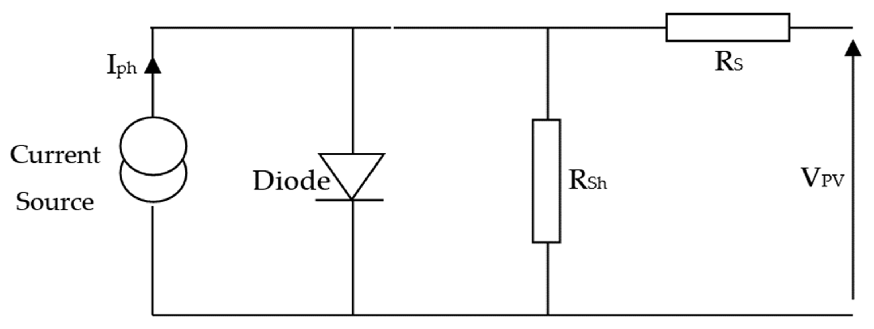
This static behavior can be described by the following mathematical Equation (1) obtained by applying Kirchoff’s law on Figure 2:
Iph = [ISC + K1 × (T − Tr)] × G/T,
The electrical model corresponding to the equation is described as following:
Knowledge that:
Iph: The photocurrent.
ISC: The current short circuit.
K: The Boltzmann constant is equal to 1.38. 10−23 J/K.
T: The temperature, in Kelvin.
RS: The series resistance.
RSh: The shunt resistance.
G: The solar irradiation in W/m2.
VCO: Open circuit voltage (when I = 0).
The electrical characteristics values of the PV panel assessed in this paper are given in the Table 1.
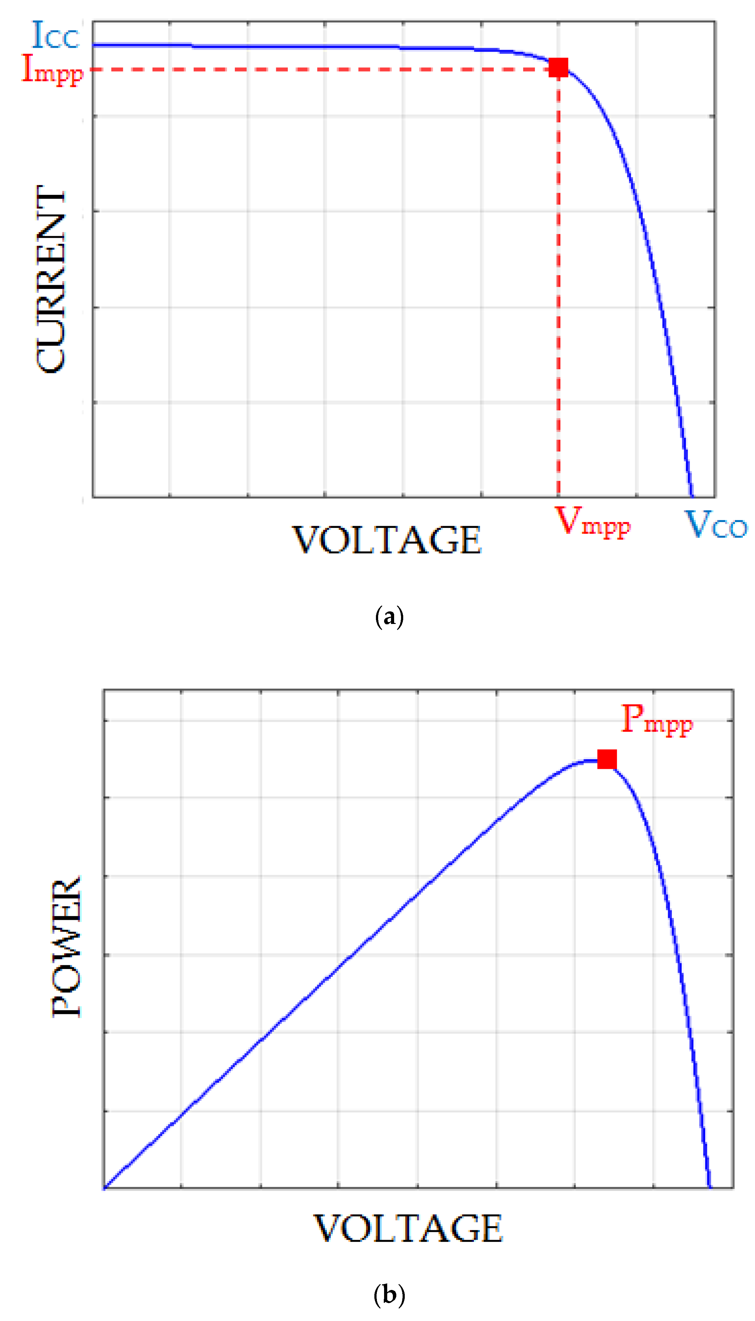
The current–voltage characteristic is a non-linear characteristic with a single optimal point where the power is maximum Pmpp [16]. The corresponding optimal voltage and current are Vmpp and Impp, as shown in Figure 3 [17].

2.2. Modeling of Boost Converter

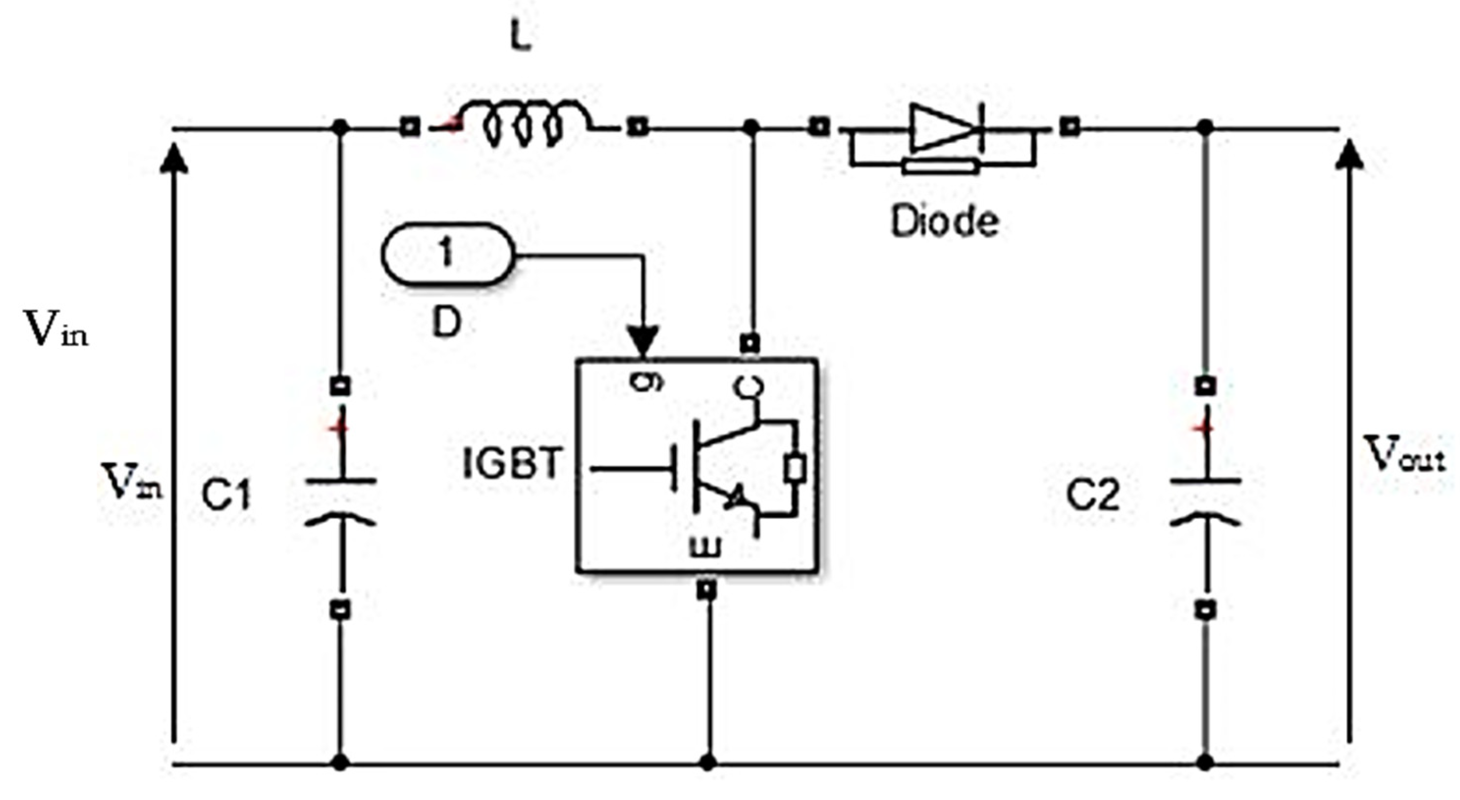
The boost converter is an interface that allows the adaptation between the PV panel and the load to extract the maximum power from the panel [18]. Figure 4 shows a boost converter that converts the input DC voltage to a higher output voltage. This converter consists of the switch (S), the inductor (L), the diode that protects S by preventing current feedback, and the capacitor C2 which is used to smooth the output voltage [19].
Where
F: Frequency;
D: Duty cycle;
R: Load resistance.
The output voltage is given by the mathematical expression follow:
Vout = Vin/(1 − D),
Knowledge that:
C = (D × Vout)/(F × R × ∆V),
and
Vin = (F × L × ∆I)/D,

2.3. MPPT Algorithms

MPPT controls based on maximizing the output power produced by the PV generator. In the literature, there are different types of algorithms based on MPPT with more or less precision [20]. These algorithms use the value of the power supplied by the photovoltaic generator for the application of an adequate control action for the follow-up of the maximum power point [20,21]. The advantages of these controls are their accuracy and speed of reaction [21].
The performance of MPPT depends on how quickly it reaches the maximum power point, how well it oscillates around it, and how robust it is to abrupt atmospheric changes [22]. Recently, the MPPT technique has become the focus of a significant amount of research to improve the dynamic performance of the PV system, primarily in terms of the ability to quickly pursue the global power point in the presence of other local maximums during various shading conditions [23].

2.3.1. Incremental Conductance Algorithm

The incremental conductance (INC) algorithm is a classic MPPT technique that uses two probes to measure the operating voltage V and the current I of the PV module [24]. This method relies on the fact that the derivative of the output power P with respect to the PV module voltage V is equal to zero at the maximum power point (MPP) [25].
The objective of INC algorithm leads to the following set of equations [26]:
(dP/dt) = 0    When    V = VMPP
(dP/dt) > 0    When    V < VMPP
(dP/dt) < 0    When    V > VMPP
Knowing that the derivate of Power P devised by the derivate of Voltage V gives the following expression:
dP/dV = d(V × I)/dV = I × (dV/dI) + V × (dI/dV) = I + V × (dI/dV)
This amounts to writing:
dI/dV = −(I/V)
Incremental changes in dV and dI are obtained by comparing the most recent measured values of voltage V and current I to those measured during the previous cycle [25,26]:
dV (K) ≈ V (K) −V (K − 1)
dI (K) ≈ I (K) − I (K − 1)
The basis of the function to find the MPP uses the following conditions:
dI/dV = −(I/V)
dI/dV > −(I/V)
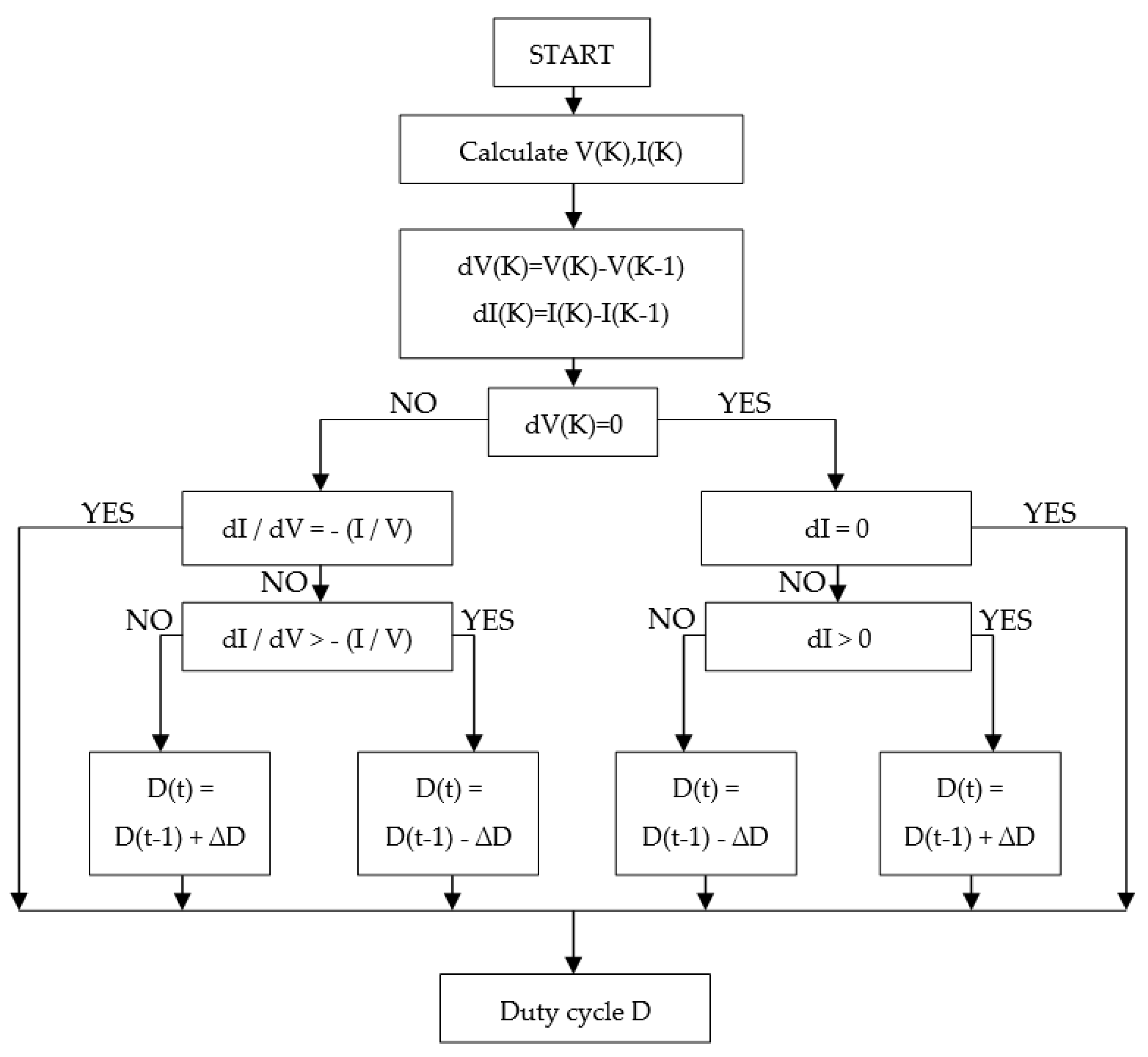
If Equation (12) is true, the MPP is reached and no change in the voltage V (k) is necessary. If Equation (12) is false, and V (k) is superior or inferior to VMPP, the voltage V (k) is adjusted accordingly [26]. Figure 5 presents the flowchart of INC algorithm.
If the system was working at MPP during the previous cycle, the incremental change in operating voltage will be zero dV(k) = 0. This would result in a division by zero error. If dI = 0, the system voltage adjustment is skipped [27]. If dI ≠ 0, Equations (6) and (7) are used to determine if the system operates over or under the VMPP and an adjustment corresponding to the operating voltage will be made accordingly [26,27].

2.3.2. Modified Incremental Conductance Algorithm

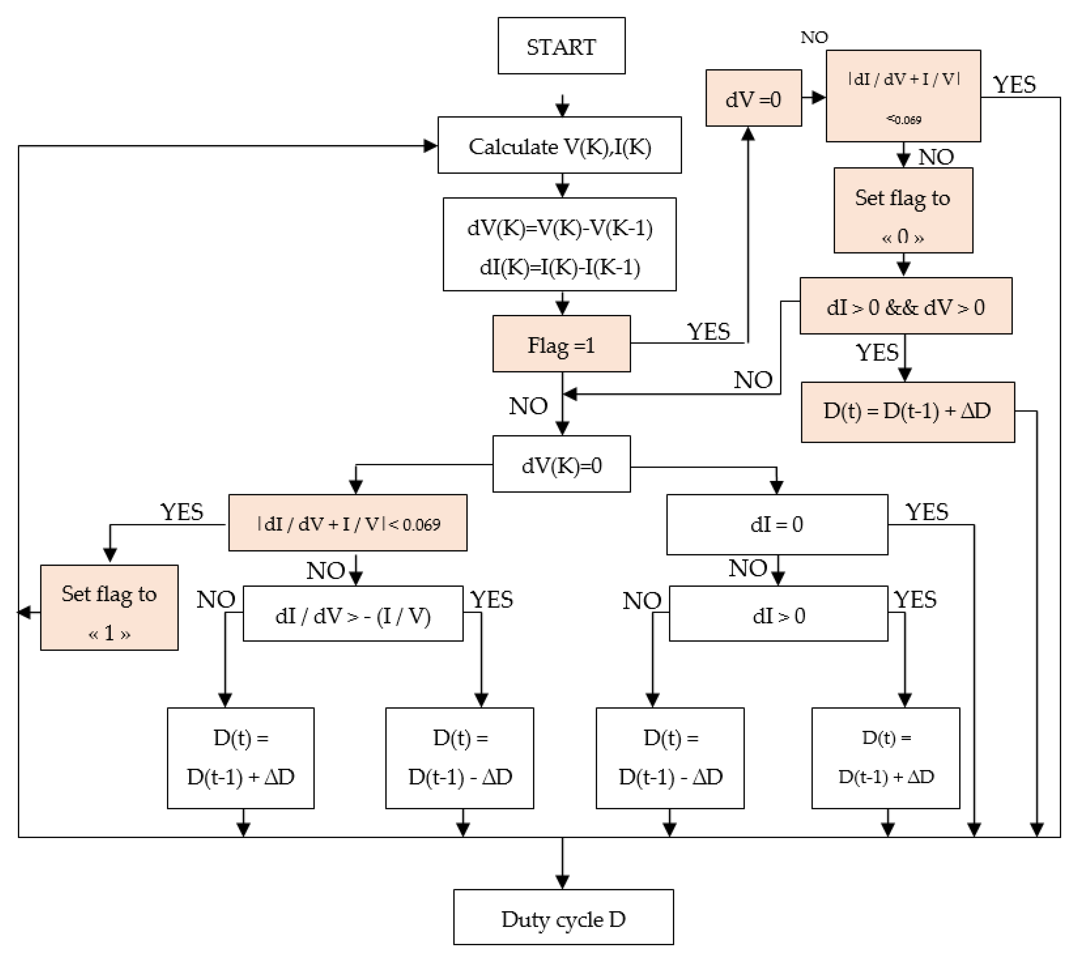
This algorithm is a modified version of conventional INC. At the beginning, a flag value is fixed to zero “0”, to specify that the MPP is achieved when the flag is set to “1” [28]. If the flag is equal to “0”, the INC is applied using the Equation (14), when this condition is attained the PV system operates at its maximum; consequently, the algorithm will set the indicator to “1” and then switches to modified algorithm. In this improved method, the program stills to verify the condition in the Equation (14) [29]. If the irradiance and load resistance are kept unchanged, no variations are made to the duty cycle; when the irradiance or load changes, the algorithm sets the flag to “0” and figures the changes in PPV and IPV [28,29]; if the algorithm detects that the voltage and current have been increased, then the duty cycle increases too; and INC algorithm is modified to overcome the imprecise response during the increase in solar irradiance [30].
Figure 6 presents the flowchart of modified INC algorithm.

2.3.3. Fuzzy Logic Controller

Fuzzy logic controllers have been widely used in industrial applications in recent years because of their heuristic nature associated with simplicity, efficiency, and the consideration of its multi-rule variable for the variation of the linear and non-linear parameters of the system [31]. The fuzzy system is composed of a system of rules based on knowledge; the main part of FLC is the knowledge of the base composed of the If-Then rules [32]. Fuzzy Logic is implemented to get the MPP operating voltage point faster with less overshoot; it can also minimize overshoot and the voltage fluctuation after extracting MPPT. The control objective is to track the maximum power in order to make the PV panel operating with high efficiency [33,34]. To design FLC, the variables that represent the dynamic performance of the system must be chosen as inputs. This algorithm is better adapted to non-linear systems, it consists of three blocks: fuzzification, inference, and defuzzification [35].
  • Fuzzification: Allows the conversion of physical input variables into fuzzy sets. In this paper [36], there aretwo inputs, the error E(K) and the change of error CE(K) defined as follows:
    E(K) = [Ppv(K) − Ppv(K−1)]/[Vpv(K) − Vpv(K − 1)],
    CE(K) = E(K) − E(K − 1)
  • Inference: Includes all rules or decision variables; and logical relations are created between the inputs and the output while defining the membership rules; as presented in Table 2 [37,38].
  • Defuzzification: Converts the output fuzzy subsets into numerical values.
Fuzzy logic control has been used in maximum power point tracking systems. It is a robust control and does not require the exact information of the mathematical model of the system [32]. The Figure 7 bellow presents the flowchart of fuzzy logic controller.

3. Results and Discussions

In this paper, a photovoltaic panel of Hyundai Heavy Industries HiS-M280MI is modeled, with boost converter and MPPT controllers to form the proposed photovoltaic system in this work. This system proposed has been designed and assessed using three MPPT algorithms:
  • Conventional incremental conductance (INC);
  • Modified incremental conductance (modINC);
  • Fuzzy logic controller (FLC);
Each algorithm was analyzed under partial shading conditions, by changing irradiance and temperature and implemented on Proteus-based Arduino.

3.1. Simulation Results Using Matlab/Simulink

This section presents the simulation results obtained in Matlab/Simulink environment.
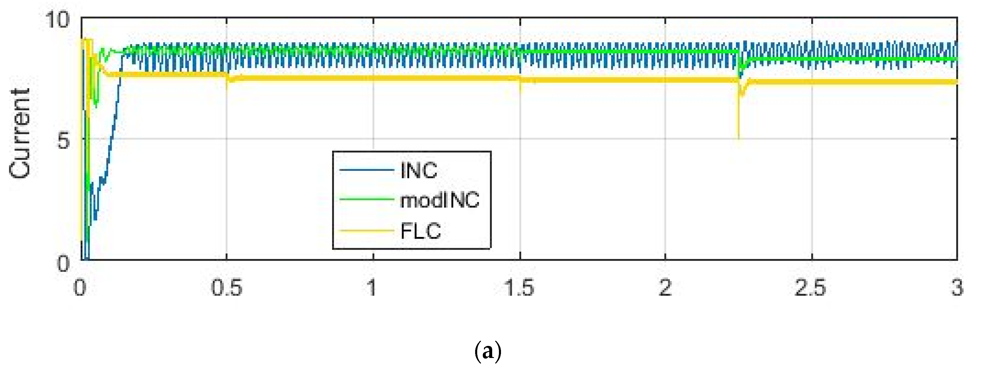
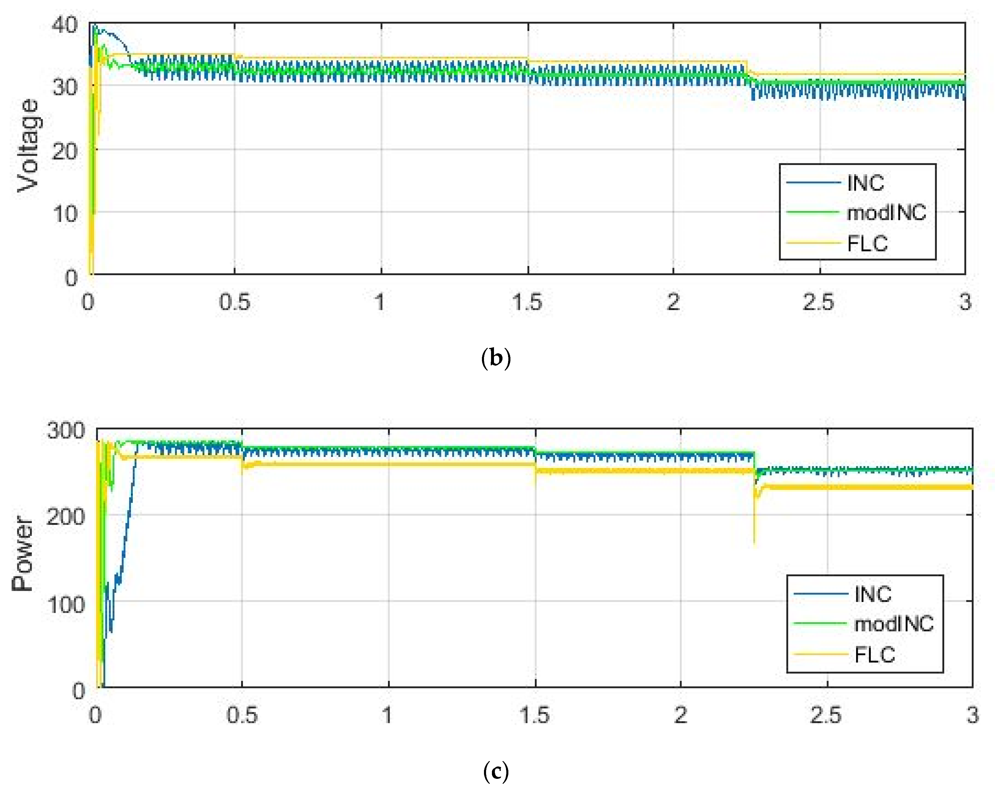
The Figure 8 shows the output current, voltage, and power using INC, modINC, and FLC in variable irradiance while temperature is fixed at 25 °C as shown in Figure 9.
The dynamic behavior of the proposed PV system has been studied in the case of changing of irradiance levels and keeping the temperature constant at 25 °C. In order to evaluate the dynamic performance of modINC, a comparative study was performed between INC, modINC, and fuzzy logic. As shown in figures above, the waveform of current, voltage, and power with INC algorithm show a slow extraction of MPP with oscillations around it.
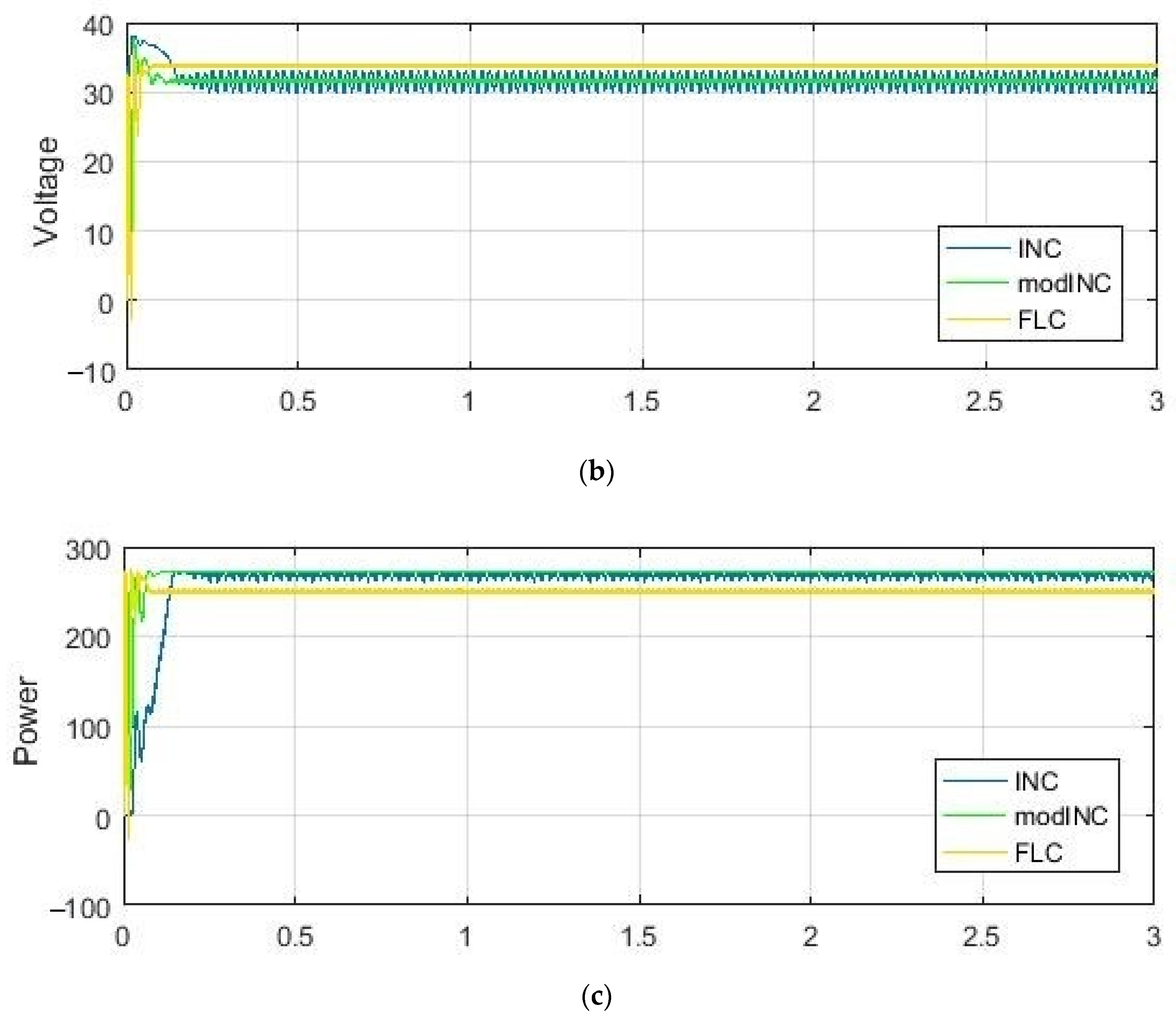
By using FLC, in Figure 8a, IMPP was reached rapidly with better stability and no oscillations around MPP. Figure 8b,c shows better convergence speed and stability when G = 800 W/m2 and G = 1000 W/m2; when G = 400 W/m2 or G = 600 W/m2, it shows a very lent extraction of MPP.
It can be concluded that by using modINC, the IMPP, VMPP, and PMPP are extracted rapidly with high convergence speed, and maximizing the energy without any oscillations around MPP.
In Figure 10, ramp change of temperature level is presented with fixed irradiance at 1000 W/m2.
The IMPP and VMPP are extracted with INC at 0.2 s with more oscillations around MPP, in each level of temperature. With FLC, the current and voltage converge fast to MPP in 0.01 s, without oscillations on output voltage, and with negligible oscillations compared to those obtained using conventional INC; and using the modINC outputs of IMPP and VMPP are obtained in better conditions with quick convergence to MPP.
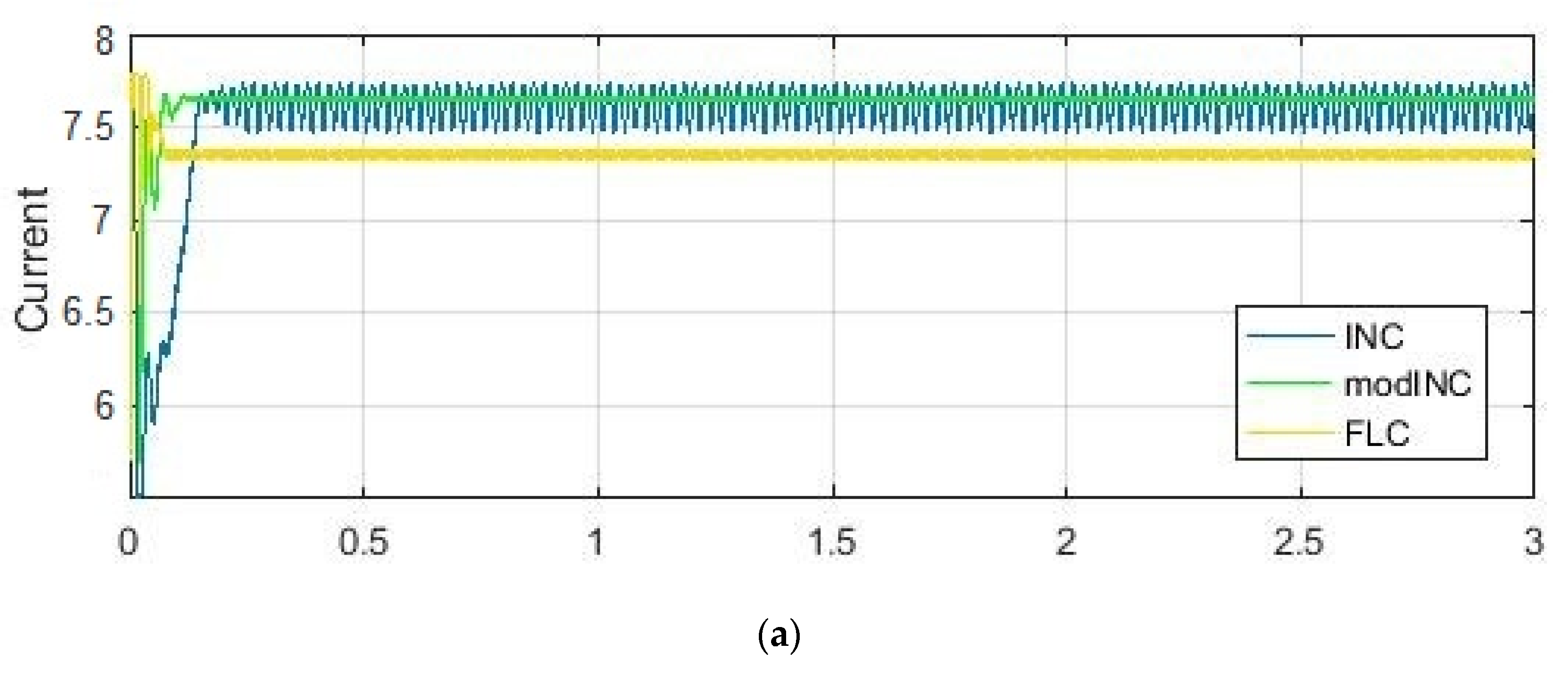
In Figure 11 below, the output current, voltage, and power are presented by changing temperature and invariable irradiance fixed at 1000 W/m2.
As shown in the figure, the power obtained using FLC is better than the one achieved with conventional INC; and the power extracted with modINC is the best one compared to the two other algorithms under variable values of temperature.
Figure 12 shows the waveforms of current, voltage, and power extracted by using INC, modINC, and FLC in standard test conditions (STC), while irradiance is equal to 1000 W/m2 and T = 25 °C.
The simulation results show that modINC is better than other suggested methods such as conventional INC and FLC in terms of efficiency, maximization of energy, convergence speed, stability, and robustness; as shown in Figure 12 above, in standard test conditions (STC) while G = 1000 W/m2 and T = 25 °C; the characteristics comparison of each algorithm are presented in Table 3.

3.2. Implementation of Three Algorithms on Proteus

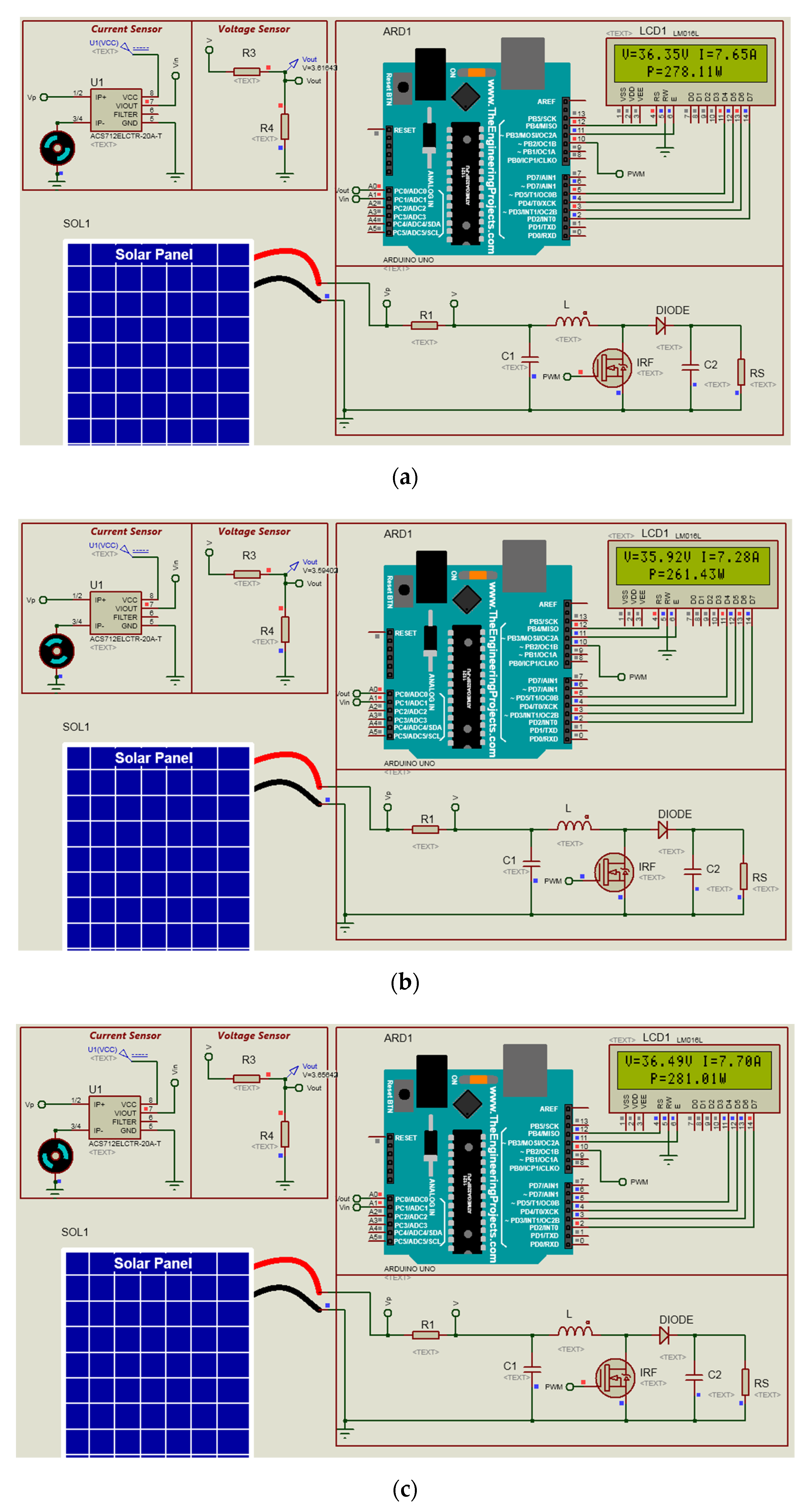
The three algorithms studied in this manuscript have been implemented on Proteus-based Arduino environment to compare the results obtained on Matlab/Simulink with PV energy measurement acquired during implementation of INC, FLC, and modINC algorithms that will be similar to the values during the real experiment. The Figure 13 shows the current, voltage, and power of the PV system by using Proteus and Arduino environments.
The measurements acquired in implementation approximate the current, voltage, and power values obtained in previous section.
The Table 3 below summarizes the performance of each algorithm studied in this manuscript:
Table 3. Characteristics comparison of each MPPT algorithm studied.
CharacteristicsINCFLCmodINC
StabilityLowHighVery High
Convergence SpeedVariesFastFast
Oscillations around MPPHighLowNo
ComplexityMediumHighMedium
EfficiencyMediumHighVery High
CostModerateExpensiveModerate
The efficiency of each MPPT algorithm presented in this manuscript was calculated by using the equation following:
Efficiency = (Ptracked/Pmax) × 100
Efficiency of FLC = (261.43/281.05) × 100 = 93.01%;
Efficiency of INC = (278.11/281.05) × 100 = 98.95%;
Efficiency of modINC = (281.01/281.05) × 100 = 99.98%.

4. Conclusions

In this paper, an assessment of some most popular MPPT techniques has been presented and studied, in order to make the photovoltaic system working at the maximum stabilized power under the variation of both temperature and irradiance. Three types of MPPT algorithms have been analyzed: the conventional incremental conductance INC, the method based on artificial intelligence fuzzy logic FLC, and the modified incremental conductance modINC. Each algorithm has been designed, analyzed, and implemented on Proteus-based Arduino. Acomparative study of the three methods in terms of efficiency, speed, and robustness under different atmospheric conditions has been presented and discussed, and a comparison between PV measurements acquired in Matlab simulation and values tracked on Proteus similar to that of real experiment is shown. The simulation and implementation results show that modINC has a higher operating power efficiency and better performance compared to the other proposed methods such as INC and FLC.

Author Contributions

Conceptualization, M.B.; methodology, M.B.; software, M.B. and M.M.; validation, M.B.; formal analysis, M.B.; investigation, M.N.S.; resources, M.B. and M.M.; data curation, M.N.S.; writing—original draft preparation, M.B.; writing—review and editing, M.B.; visualization, M.N.S.; supervision, M.N.S.; project administration, M.N.S.; funding acquisition, M.B. All authors have read and agreed to the published version of the manuscript.

Funding

This research received no external funding.

Institutional Review Board Statement

Not applicable.

Informed Consent Statement

Not applicable.

Data Availability Statement

Not applicable.

Conflicts of Interest

The authors declare no conflict of interest.

Abbreviations

The following abbreviations are used in this manuscript:
PVPhotovoltaic
TTemperature
GIrradiance
MPPTMaximum power point tracking
MPPMaximum power point
FLCFuzzy logic controller
INCIncremental conductance
modINCModified incremental conductance
PWMPulse-width-modulation
MOSFETMetal-oxide-silicon field-effect transistor
NBNegative Big
NMNegative Medium
NSNegative Small
ZEZero
PSPositive Small
PMPositive Medium
PBPositive Big

References

  1. Bouksaim, M.; Acci, Y.; Srifi, M.N. Modeling of Grid-Connected Photovoltaic System Installation in Moroccan Ibn Tofail Uni-versity. Adv. Sci. Technol. Eng. Syst. J. (ASTESJ) 2019, 4, 150–155. [Google Scholar] [CrossRef] [Green Version]
  2. Lee, H.-S.; Yun, J.-J. Advanced MPPT Algorithm for Distributed Photovoltaic Systems. Energies 2019, 12, 3576. [Google Scholar] [CrossRef] [Green Version]
  3. Feldman, D.; Barbose, G.; Margolis, R.; Bolinger, M.; Chung, D.; Fu, R.; Seel, J.; Davidson, C.; Darghouth, N.; Wiser, R. Pho-tovoltaic System Pricing Trends Historical, Recent, and Near-Term Projections 2015 Edition. Available online: https://escholarship.org/content/qt9pc3x32t/qt9pc3x32t.pdf (accessed on 2 September 2019).
  4. Arefifar, S.A.; Paz, F.; Ordonez, M. Improving Solar Power PV Plants Using Multivariate Design Optimization. IEEE J. Emerg. Sel. Top. Power Electron. 2017, 5, 638–650. [Google Scholar] [CrossRef]
  5. Ramli, M.A.; Twaha, S.; Ishaque, K.; Al-Turki, Y.A. A review on maximum power point tracking for photovoltaic systems with and without shading conditions. Renew. Sustain. Energy Rev. 2017, 67, 144–159. [Google Scholar] [CrossRef]
  6. Panagea, I.S.; Tsanis, I.K.; Koutroulis, A.; Grillakis, M. Climate Change Impact on Photovoltaic Energy Output: The Case of Greece. Adv. Meteorol. 2014, 2014, 264506. [Google Scholar] [CrossRef]
  7. Luo, H.; Wen, H.; Li, X.; Jiang, L.; Hu, Y. Synchronous buck converter based low-cost and high-efficiency sub-module DMPPT PV system under partial shading conditions. Energy Convers. Manag. 2016, 126, 473–487. [Google Scholar] [CrossRef]
  8. Rezk, H.; Fathy, A.; Abdelaziz, A.Y. A comparison of different global MPPT techniques based on meta-heuristic algorithms for photovoltaic system subjected to partial shading conditions. Renew. Sustain. Energy Rev. 2017, 74, 377–386. [Google Scholar] [CrossRef]
  9. Pilakkat, D.; Kanthalakshmi, S. An improved P&O algorithm integrated with artificial bee colony for photovoltaic systems under partial shading conditions. Sol. Energy 2018, 178, 37–47. [Google Scholar] [CrossRef]
  10. Hassan, T.-U.; Abbassi, R.; Jerbi, H.; Mehmood, K.; Tahir, M.; Cheema, K.; Elavarasan, R.; Ali, F.; Khan, I. A Novel Algorithm for MPPT of an Isolated PV System Using Push Pull Converter with Fuzzy Logic Controller. Energies 2020, 13, 4007. [Google Scholar] [CrossRef]
  11. Yildirim, M.A.; Nowak-Ocłon, M. Modified Maximum Power Point Tracking Algorithm under Time-Varying Solar Irradia-tion. Energies 2020, 13, 6722. [Google Scholar] [CrossRef]
  12. Motahhir, S.; Chalh, A.; El Ghzizal, A.; Sebti, S.; Derouich, A. Modeling of Photovoltaic Panel by using Proteus. J. Eng. Sci. Technol. Rev. 2017, 10, 8–13. [Google Scholar] [CrossRef]
  13. Daraban, S.; Petreus, D.; Morel, C. A novel MPPT (maximum power point tracking) algorithm based on a modified genetic algorithm specialized on tracking the global maximum power point in photovoltaic systems affected by partial shading. Energy 2014, 74, 374–388. [Google Scholar] [CrossRef]
  14. Bouksaim, M.; Krami, N.; Acci, Y.; Srifi, M.N.; Hadjouja, A. Modeling of Photovoltaic Module Using Maximum Power Point Tracking Controller. In Proceedings of the 2018 International Symposium on Advanced Electrical and Communication Technologies (ISAECT), Rabat, Morocco, 21–23 November 2018; pp. 1–4. [Google Scholar] [CrossRef]
  15. Al Tarabsheh, A.; Akmal, M.; Ghazal, M. Series Connected Photovoltaic Cells—Modelling and Analysis. Sustainability 2017, 9, 371. [Google Scholar] [CrossRef] [Green Version]
  16. Vergura, S. A Complete and Simplified Datasheet-Based Model of PV Cells in Variable Environmental Conditions for Circuit Simulation. Energies 2016, 9, 326. [Google Scholar] [CrossRef]
  17. Yatimi, H.; Aroudam, E. Mathematical Modeling and Simulation of Photovoltaic Power Source using Matlab/Simulink. Int. J. Innov. Appl. Stud. 2016, 16, 322–330. [Google Scholar]
  18. Abouchabana, N.; Haddadi, M.; Rabhi, A.; Grasso, A.D.; Tina, G.M. Power Efficiency Improvement of a Boost Converter Using a Coupled Inductor with a Fuzzy Logic Controller: Application to a Photovoltaic System. Appl. Sci. 2021, 11, 980. [Google Scholar] [CrossRef]
  19. Marina, S.P.; João Pedro, F.T.; Alonso, J.M.; Saraiva, E.S. Large-Signal Characterization of Power Inductors in EV Bidirec-tional DC-DC Converters Focused on Core Size Optimization. IEEE Trans. Ind. Electron. 2015, 62, 3042–3051. [Google Scholar]
  20. Zhang, P.; Sui, H. Maximum Power Point Tracking Technology of Photovoltaic Array under Partial Shading Based on Adaptive Improved Differential Evolution Algorithm. Energies 2020, 13, 1254. [Google Scholar] [CrossRef] [Green Version]
  21. Islam, H.; Mekhilef, S.; Shah, N.B.M.; Soon, T.K.; Seyedmahmousian, M.; Horan, B.; Stojcevski, A. Performance Evaluation of Maximum Power Point Tracking Approaches and Photovoltaic Systems. Energies 2018, 11, 365. [Google Scholar] [CrossRef] [Green Version]
  22. Verma, D.; Nema, S.; Shandilya, A.M.; Dash, S.K. Maximum power point tracking (MPPT) techniques: Recapitulation in so-lar photovoltaic systems. Renew. Sustain. Energy Rev. 2016, 54, 1018–1034. [Google Scholar] [CrossRef]
  23. Aquib, M.; Jain, S.; Agarwal, V. A Time-Based Global Maximum Power Point Tracking Technique for PV System. IEEE Trans. Power Electron. 2019, 35, 393–402. [Google Scholar] [CrossRef]
  24. Li, C.; Chen, Y.; Zhou, D.; Liu, J.; Zeng, J. A High-Performance Adaptive Incremental Conductance MPPT Algorithm for Photovoltaic Systems. Energies 2016, 9, 288. [Google Scholar] [CrossRef] [Green Version]
  25. Visweswara, K. An Investigation of Incremental Conductance based Maximum Power Point Tracking for Photovoltaic System. Energy Procedia 2014, 54, 11–20. [Google Scholar] [CrossRef] [Green Version]
  26. Vital Rao, P.; Sudha, K.R.; Prameela Devi, S. Incremental conductance (IncCond) algorithm for Maximum Power Operating Point (MPOP) of Photo-Voltaic (PV) power generation system. Am. J. Eng. Res. (AJER) 2013, 2, 334–342. [Google Scholar]
  27. Mirza, A.F.; Mansoor, M.; Ling, Q.; Khan, M.I.; Aldossary, O.M. Advanced Variable Step Size Incremental Conductance MPPT for a Standalone PV System Utilizing a GA-Tuned PID Controller. Energies 2020, 13, 4153. [Google Scholar] [CrossRef]
  28. Tey, K.S.; Mekhilef, S. Modified incremental conductance MPPT algorithm to mitigate inaccurate responses under fast-changing solar irradiation level. Sol. Energy 2014, 101, 333–342. [Google Scholar] [CrossRef]
  29. Motahhir, S.; El Ghzizal, A.; Sebti, S.; Derouich, A. Modeling of Photovoltaic System with Modified Incremental Conductance Algorithm for Fast Changes of Irradiance. Int. J. Photoenergy 2018, 2018, 3286479. [Google Scholar] [CrossRef]
  30. De Brito, M.A.G.; Galotto, L.; Sampaio, P.L.; de Azevedo e Melo, G.; Canesin, C.A. Evaluation of the main MPPT techniques for photovoltaic applications. IEEE Trans. Ind. Electron. 2013, 60, 1156–1167. [Google Scholar] [CrossRef]
  31. Asif, R.M.; Rehman, A.U.; Rehman, S.U.; Arshad, J.; Hamid, J.; Sadiq, M.T.; Tahir, S. Design and analysis of robust fuzzy logic maximum power point tracking based isolated photovoltaic energy system. Eng. Rep. 2020, 2, e12234. [Google Scholar] [CrossRef]
  32. Bakkar, M.; Aboelhassan, A.; Abdelgeliel, M.; Galea, M. PV Systems Control Using Fuzzy Logic Controller Employing Dynamic Safety Margin under Normal and Partial Shading Conditions. Energies 2021, 14, 841. [Google Scholar] [CrossRef]
  33. Livinti, P. Comparative Study of a Photovoltaic System Connected to a Three-Phase Grid by Using PI or Fuzzy Logic Controllers. Sustainability 2021, 13, 2562. [Google Scholar] [CrossRef]
  34. Napole, C.; Derbeli, M.; Barambones, O. Fuzzy Logic Approach for Maximum Power Point Tracking Implemented in a Real Time Photovoltaic System. Appl. Sci. 2021, 11, 5927. [Google Scholar] [CrossRef]
  35. Al-Majidi, S.D.; Abbod, M.F.; Al-Raweshidy, H.S. A novel maximum power point tracking technique based on fuzzy logic for photovoltaic systems. Int. J. Hydrogen Energy 2018, 43, 14158–14171. [Google Scholar] [CrossRef]
  36. Kechiche, O.B.H.B.; Barkaoui, B.; Hamza, M.; Sammouda, H. Simulation and comparison of P&O and fuzzy logic MPPT techniques at different irradiation conditions. In Proceedings of the 2017 IEEE International Conference on Green Energy Conversion Systems (GECS), Hammamet, Tunisia, 23–25 March 2017. [Google Scholar]
  37. Algarín, C.R.; Giraldo, J.T.; Álvarez, O.R. Fuzzy Logic Based MPPT Controller for a PV System. Energies 2017, 10, 2036. [Google Scholar] [CrossRef] [Green Version]
  38. Jasmin, E.R.; James, J. Implementation of fuzzy logic based maximum power point tracking in photovoltaic system. In Proceedings of the International Conference on Control, Communication and Power Engineering 2014—CCPE 2014, Chennai, India, 21–22 February 2014; pp. 547–556. [Google Scholar]
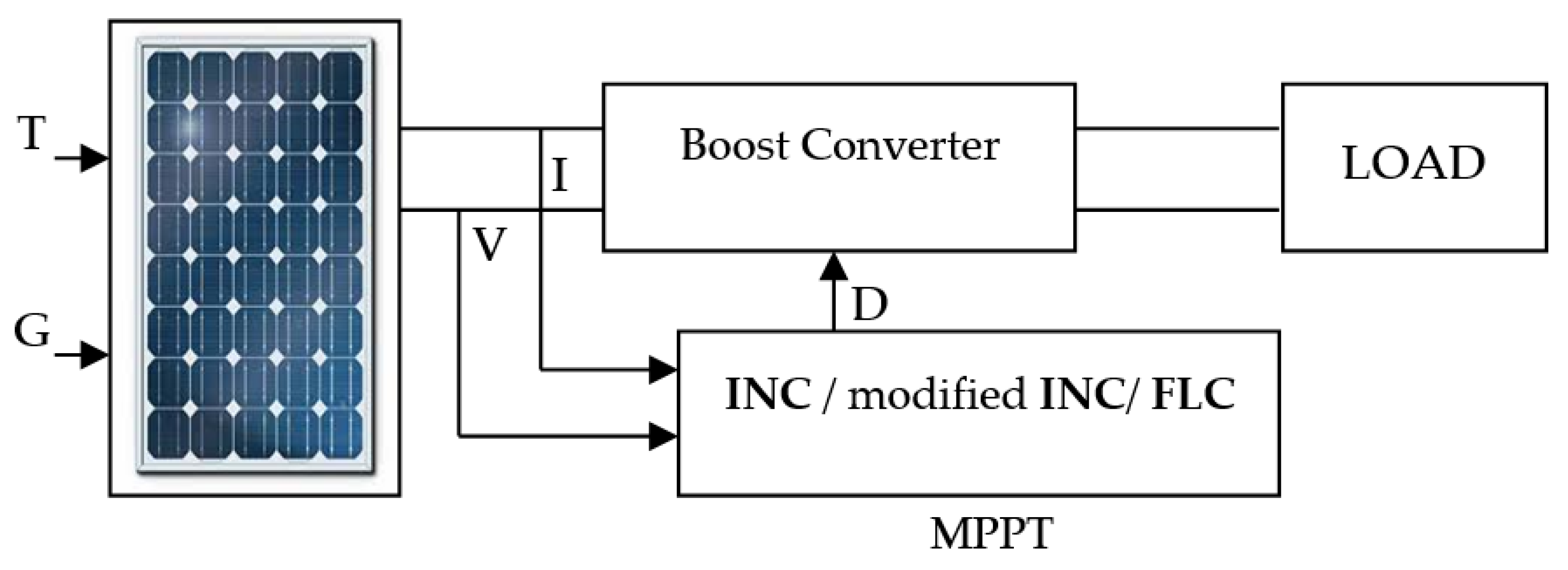
Figure 1. Block diagram of the proposed PV system.
Designs 05 00071 g001
Figure 2. Equivalent circuit of PV panel.
Designs 05 00071 g002
Figure 3. (a) Current–voltage characteristic; (b) power–voltage characteristic.
Designs 05 00071 g003
Figure 4. Electrical circuit of boost converter.
Designs 05 00071 g004
Figure 5. Flowchart of INC algorithm.
Designs 05 00071 g005
Figure 6. Flowchart of modified INC algorithm.
Designs 05 00071 g006
Figure 7. Flowchart of fuzzy logic controller.
Designs 05 00071 g007
Figure 8. (a) Output current using INC, modINC, and FLC, by changing the irradiance. (b) Output voltage using INC, modINC, and FLC, by changing the irradiance. (c) Output power using INC, modINC, and FLC, by changing the irradiance.
Designs 05 00071 g008
Figure 9. (a) Invariable temperature, it is set at 25 °C. (b) Ramp change of irradiance level.
Designs 05 00071 g009
Figure 10. (a) Ramp change of temperature level. (b) Invariable irradiance, set at 1000 W/m2.
Designs 05 00071 g010
Figure 11. (a) Output current using INC, modINC, and FLC, by changing the temperature. (b) Output voltage using INC, modINC, and FLC, by changing the temperature. (c) Output power using INC, modINC, and FLC, by changing the temperature.
Designs 05 00071 g011aDesigns 05 00071 g011b
Figure 12. (a) Output current using INC, modINC, and FLC in STC. (b) Output voltage using INC, modINC, and FLC in STC. (c) Output power using INC, modINC and FLC in STC.
Designs 05 00071 g012aDesigns 05 00071 g012b
Figure 13. (a) PV energy measurement using INC on Proteus-based Arduino. (b) PV energy measurement using FLC on Proteus-based Arduino. (c) PV energy measurement using modINC on Proteus-based Arduino.
Designs 05 00071 g013
Table 1. Electrical characteristics of PV panel Hyundai Heavy Industries HiS-M280MI.
Electrical CharacteristicsValues
Maximum Power281.05 W
Number of cells72
Imp7.7 A
Vmp36.5 V
ISC8.3 A
VOC44.4 V
Table 2. Fuzzy rules sets.
E/CENBNSZEPSPB
NBZEZEPBPBPB
NSZEZEPSPSPS
ZEPSZEZEZENS
PSNSNSNSZEZE
PBNBNBNBZEZE
Publisher’s Note: MDPI stays neutral with regard to jurisdictional claims in published maps and institutional affiliations.