1. Introduction
The aerodynamic properties of conventional airplane wings can be altered using flaps, slats, and ailerons on the exterior of the wing. These components serve to alter the geometry and surface area of the wing, but their use is accompanied by an unwanted drag and thus a lower fuel efficiency. Conventional wings accomplish only limited mission objectives and cannot be optimized for the entire flight envelope [
1]. Morphing wings, in contrast, can change their geometric configurations at different points of the flight envelope to significantly improve the aerodynamic performance at various flight conditions in a variety of missions and functions [
2]. However, the need to develop a wing structure that is stiff enough to carry aerodynamic loads and, at the same time, flexible enough to morph, poses many design challenges, especially if a seamless skin is sought.
The optimal wingspan required at different flight conditions is different from the fixed wingspan selected in a traditional aircraft design based on the cruise condition. Wings with large span have good range and fuel efficiency but have relatively low cruise speeds and lack maneuverability. Aircrafts with low aspect ratio wings, on the other hand, can fly faster and can become more maneuverable, but show poor aerodynamic efficiency [
3]. Hence, wings with an adjustable wingspan are capable of improving the overall flight performance. Changing the wingspan directly alters the surface area of the wing, which affects the lift generated by the wing. Adjusting the span length, while maintaining a constant airfoil cross-sectional area during flight, enables the optimization of endurance, maneuverability, stability, fuel efficiency, and roll control at any specific flight condition [
4]. Span morphing can be done symmetrically, where both wings are morphed identically and simultaneously, or asymmetrically, where the morphing of one wing is different from the other one. Asymmetric morphing would allow for roll control without the need for traditional ailerons [
4]. The variety of modes in span length morphing introduces added benefits, due to their adaptability to flight conditions and mission profiles.
Dramatic wing configuration changes have been explored [
2]. The oldest and most common concept of wing span morphing is the telescoping wing design. An example of such a design was developed by Blondeau and Pines [
5]. Telescoping wings do not need flexible skin, but are usually heavier and more complex than other designs. In addition, telescoping usually takes place at the outer surface of the wing leading to discontinuities or a wing with a nonuniform cross section. Designing a successful and practical span-morphing wing requires developing a lightweight effective wing core with an actuation system, and a compliant wing skin that maintains its shape at all morphing configurations. The core should support the skin, carry the aerodynamic loads, and maintain the airfoil shape during morphing. The skin should have a proper directional stiffness that can deform with morphing without producing significant Poisson’s ratio effect and should maintain proper tautness at all morphing configurations.
Different core designs for span morphing wings have been presented. Vocke III et al. [
6] presented a core with a zero Poisson’s ratio that can extend and slide over carbon fiber spars. Ajaj et al. [
4] introduced the idea of the Zigzag wingbox that is composed of various morphing partitions, where each partition has some hinged beams that change the span of the partition upon actuation. Woods and Fristwell [
7] introduced the Adaptive Aspect Ratio (AdAR) concept that includes a telescopic rectangular box spar, sliding ribs and a strap driven system for actuation. Ajaj et al. [
8] developed a span morphing wing with a compliant spar. This wing is also divided into multiple partitions, where the spar in each partition is made of a series of compliant joints in the form of concentric overlapping tubes that can change the span of the partition. Ajaj et al. [
9] presented the idea of the Gear driveN Autonomous Twin Spar (GNATSpar) wing for a mini-unmanned aerial vehicle (UAV). The spar of each side of the wing in this design extends to the opposite side through a rack-and-pinion mechanism to vary the wingspan length. Each of the aforementioned ideas comes with its own design challenges and complexities. Accordingly, Ajaj and Jankee, in their recent work [
10], designed, built and flight-tested a span-morphing UAV, but relied on the old, well-established telescoping concept.
Span morphing wings require not just flexible skin, but stretchable skin that can significantly expand without buckling or producing an excessive Poisson’s-ratio effect. Multiple studies presented designs and fabrication details of flexible/stretchable skins with a near-zero Poisson’s ratio, for morphing wing applications [
11,
12,
13,
14]. La et al. [
15] recently presented a survey on the status and challenges of designing skins for aircrafts with morphing wings. Ajaj et al. [
9] used flexible elastomeric skin on their GNATSpar wing design with 5% pre-tension. This 0.5 mm-thick latex skin increased the required actuation force and had a significant Poisson’s effect that resulted in a nonuniform airfoil shape along the span. Hence, it was suggested that flexible skins with a lower Young’s modulus, such as Tecoflex and Rhodorsil V-330/CA-35 Silicone elastomers, be used to improve the skin behavior. Bubert et al. [
12] and Vocke III et al. [
6] developed an elastomeric-matrix-composite (EMC) skin made of Rhodorsil V-330/CA-35 silicone rubber with embedded chordwise unidirectional carbon fibers. This skin had a near-zero Poisson’s effect. Recently, Jakubinek et al. [
16,
17] developed a stretchable skin based on carbon nanotube-polyurethane sheets with approximately 25 wt% carbon nanotubes.
This paper presents an improved design for the core structure of the span-morphing wing presented in Reference [
6]. The new design features an assembled honeycomb substructure made of flexible chevrons, integrated with rigid internal ribs. This results in spanwise compliance to enable morphing, with a transverse rigidity to effectively carry the aerodynamic loads. This is in contrast to the design in Reference [
6] that was made of one flexible material, and hence lacked the benefit of having varied directional stiffness. The new honeycomb substructure is also much easier to manufacture than that reported in Reference [
6], since it eliminates the need for 3D-printed support structures, if a fused deposition modeling (FDM) 3D printer is used. It also avoids all complications that come from printing one large complicated structure in a single 3D printing job. In addition, telescoping carbon fiber tubes are used to replace the idea of sliding ribs on a fixed spar, presented in Reference [
6]. The telescoping action is done in each partition, hence effectively and efficiently utilizing the precious space inside the wing. The model in Reference [
6] did not include any actuators. The current work uses linear actuators in the core of each partition to morph the wing. Structural analyses of the span-morphing partition have been performed to ensure the ability of the wing to carry the aerodynamic loads without significant transverse deformations, and to assess the ability of the linear actuators to generate the required forces to actuate the wing partitions in both directions. The proposed design has been manufactured, assembled and tested. The testing results qualitatively confirmed all computational simulations and proved the effectiveness of the new design.
Appendix A presents some of the aforementioned designs in the literature, some drawbacks based on the authors’ opinion, and the improvements that the proposed design offers in order to avoid such drawbacks.
The rest of this paper is organized as follows:
Section 2 introduces the new design of the wing core;
Section 3 presents the structural analyses performed and the computational results;
Section 4 addresses some manufacturing details;
Section 5 covers testing. This is followed by a final summary and conclusion.
2. Wing Core Design
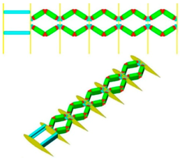
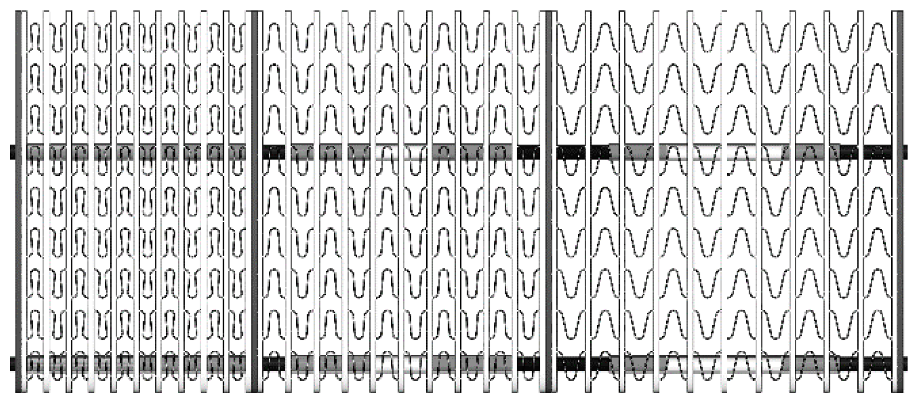
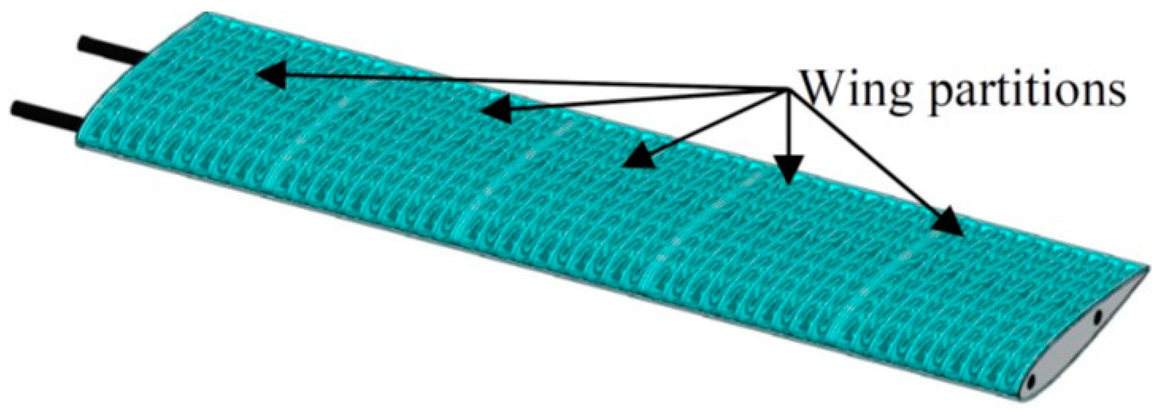
The design requirements for the morphing wing core were: (1) change the wingspan by 50% from the compressed state to the expanded state, (2) maximize the transverse and chordwise stiffness while keeping the spanwise stiffness low to enable morphing, (3) support a seamless, stretchable skin without changing the airfoil shape along the wing span, (4) use lightweight materials for the wing load-carrying structure and ensure no failure or large deformations to this structure under the expected aerodynamic loads. The UAV wing shape is rectangular, with a chord length of 27 cm and baseline (non-morphed) span length of 102 cm. Compressed and extended span lengths of 81.6 cm and 122.4 cm, respectively, were chosen to reflect a fifty percent span length increase from the compressed configuration. The NACA 0015 standard symmetrical airfoil was chosen for its high lift-to-drag ratio. The wing comprises five partitions, as can be seen in
Figure 1. Each partition can be compressed or extended as shown in
Figure 2.
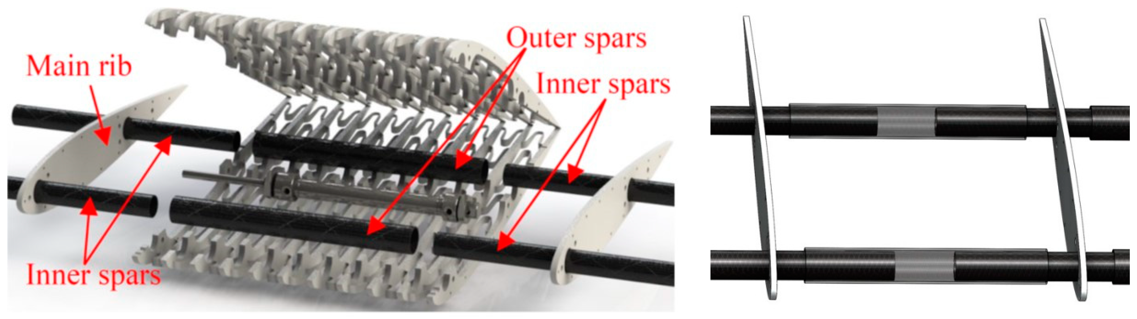
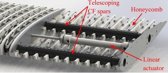
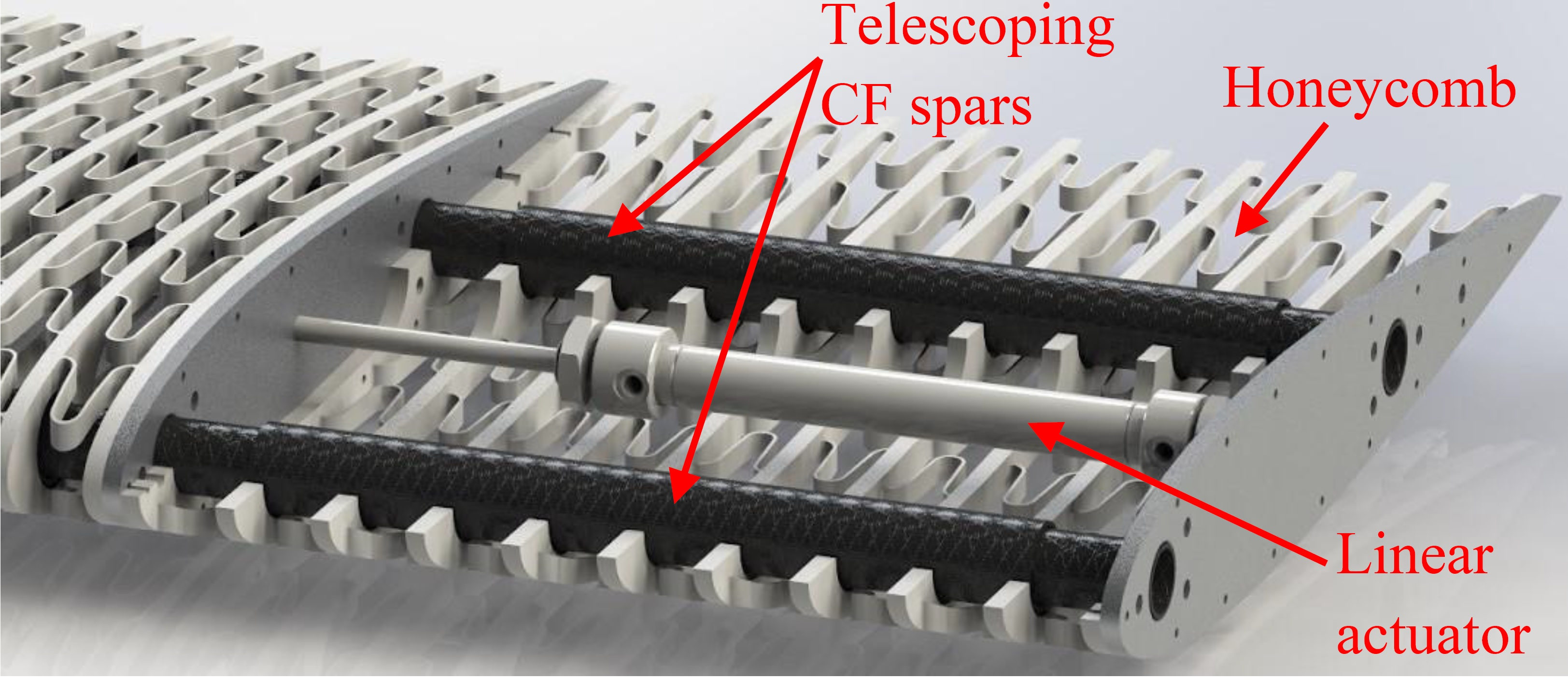
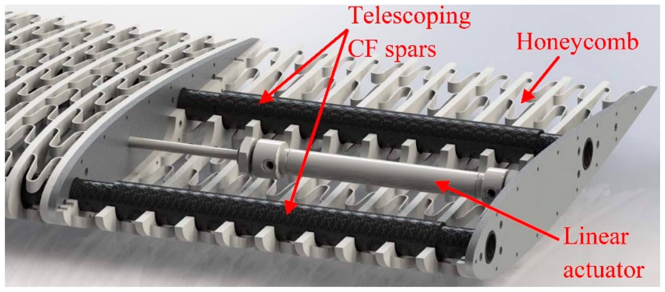
Three main components make up the structure of each partition, as shown in the cutaway view in
Figure 3: A zero Poisson’s ratio honeycomb substructure, two telescoping carbon fiber spars, and a linear actuator. The zero Poisson’s ratio honeycomb substructure allows for a fifty percent extension while maintaining the airfoil shape and the cross-sectional area. The telescoping carbon fiber tubes interconnect to provide the main structure of the wing. Linear actuators in all partitions provide the means of actuating the entire wing.
The whole wing can be covered by a seamless, continuous, pre-tensioned and stretchable latex skin or composite skin of silicone rubber matrix with embedded unidirectional chordwise carbon fibers. This skin allows for spanwise extension while maintaining chordwise stiffness. Along with the honeycomb substructure, the chordwise orientation of the carbon fibers in the skin ensures a near-zero Poisson’s ratio while morphing occurs. Similar skin designs have been developed by Bubert et al. [
12] and Chen et al. [
14]. Compared to the designs in References [
4,
9] (figures in
Appendix A), the proposed design avoids the significant nonuniformity of the airfoil shape along the span because of the presence of internal ribs and chevrons to support the skin between the main ribs.
2.1. Assembled Honeycomb Substructure
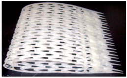
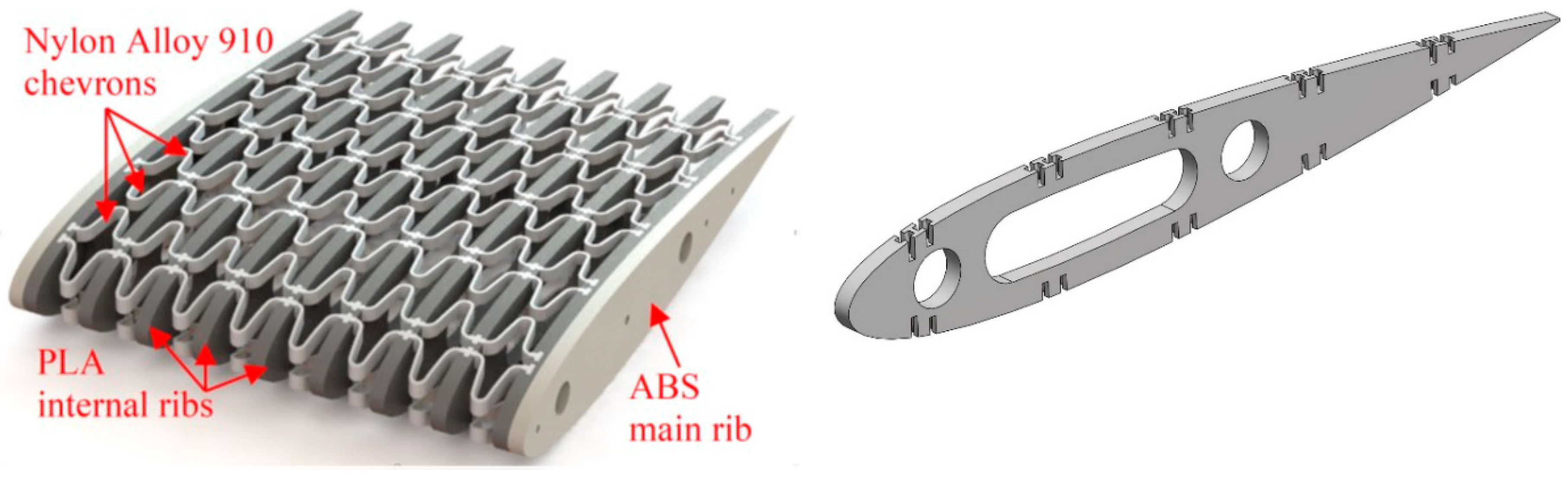
The honeycomb substructure, presented for the first time in Reference [
6], was 3D printed of acrylic-based photopolymer as one piece. This was replaced in the proposed design by an assembly of flexible interconnecting beams or “chevrons” made of Nylon Alloy 910, connected to rigid internal ribs made of polylactic acid (PLA) as shown in
Figure 4 (left). Because of the rigid internal ribs, this modified design has a much stronger transverse and chordwise rigidity to support the skin and carry the aerodynamic loads without significant transverse deformations, while still featuring the spanwise compliance provided through the flexible chevrons. The design maintains the constant airfoil shape and cross-sectional area, which is not guaranteed in the flexible design in Reference [
6].
Figure 4 (right) shows the internal rib design. The chevron design was also modified to take the shape of a cosine wave, which reduces the stress concentrations that can develop around the sharp curves of the honeycomb design in Reference [
6]. The honeycomb substructure is fastened to the main spar/rib structure of the wing as shown in
Figure 5.
2.2. Interconnected Telescoping Spars
The spar assembly provides structural rigidity and resists bending of the wing under aerodynamic loads. In contrast to past designs which relied on either a traditional single carbon fiber spar, with telescoping taking place within the fuselage, or spars that fold within the morphing partition [
4,
6,
18], the proposed design relies on interconnected, telescoping carbon fiber spars, with the telescoping action taking place within each partition of the wing. The benefit of this design is that it keeps the actuation within the individual morphing partitions, thus utilizing the space inside the wing more efficiently and providing more support to the honeycomb substructure than what the zigzag concept offers [
4], for example.
The central outer spar is attached to the central internal rib of the honeycomb to prevent unwanted side-to-side motion. The inner spars pass through and are bonded to the main ribs, as shown in the exploded view in
Figure 5. In order to keep the spars from moving too far apart and the center spar from becoming dislodged, the linear actuators limit the ultimate extension and contraction of the system. This allows the system to achieve the motion necessary for morphing, while locking the structure in place for both the compressed and extended configurations. A layer of Teflon between the inner and outer spars is used to minimize the sliding friction.
The carbon fiber tubes are made of layers of interwoven T300 carbon fibers. The main ribs, 3D printed of acrylonitrile butadiene styrene (ABS), are bonded to the inner carbon fiber hollow spars. These inner spars have a total length of 16.7 cm, an outer diameter of 13 mm and inner diameter of 11 mm. Teflon tubes with an outer diameter of 15 mm are affixed to the outside of the inner spars. The outer spars have an outer diameter of 18 mm, inner diameter of 16 mm and length of 16.3 cm.
3. Simulations
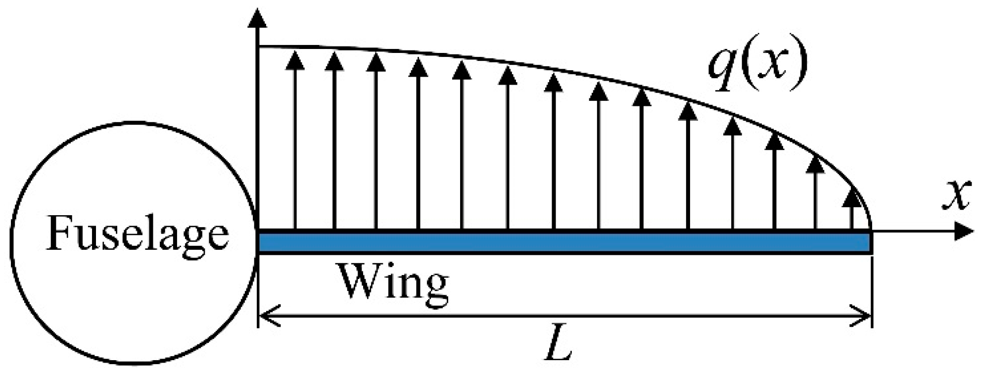
To analyze the effect of the aerodynamic loads on the major components of the proposed design, SOLIDWORKS Simulation (version 2017 by Dassault Systemes, Vélizy-Villacoublay, France) was used to perform a finite element analysis (FEA) on the developed model. A static analysis was performed on the spars to determine the maximum displacement under aerodynamic loads. First, an elliptical load distribution was assumed over the wing as shown in
Figure 6.
Equation (1) represents the distribution of the load,
q(
x), the wing experiences based on the weight of the aircraft and the weight of the wing [
19].
Wtotal is the total weight of the UAV (assumed to be 15 Kg, which is an average weight of a typical UAV of the same size),
Wwing is the weight of the wing (assumed to be
Wtotal/8, which is a commonly used estimate for the weight of the wing),
n is the load factor (defined as lift/total weight, and taken to be 1.5 here),
L is the span length, and
x is the position measured from the wing root along the span. The load can be discretized and broken down into six individual distributed loads to be applied to the six main ribs for analysis. Since the loads were transferred from the skin and the honeycomb substructure to the spars via the six main ribs, only the six ribs and the interconnected spars were used in this simplified bending analysis. Each rib had two spars running through it, as shown in
Figure 7. The reaction forces between the ribs and the spars were analyzed, showing that the rear and front spars take 2/3 and 1/3 of the total load, respectively. Hence, another analysis was conducted on the rear spar separately, where the root of the spar was constrained, and two-thirds of the total load was applied at the locations of the six main ribs. Split lines were created in SOLIDWORKS to simulate where the ribs are located on the spars. A convergence analysis was performed on both the compressed and extended configurations. The maximum displacement occurred at the tip of the wing for both configurations, as anticipated. The maximum displacement of the spar assembly was 7 mm and 15 mm for the compressed and extended configurations, respectively, with large strength ratios.
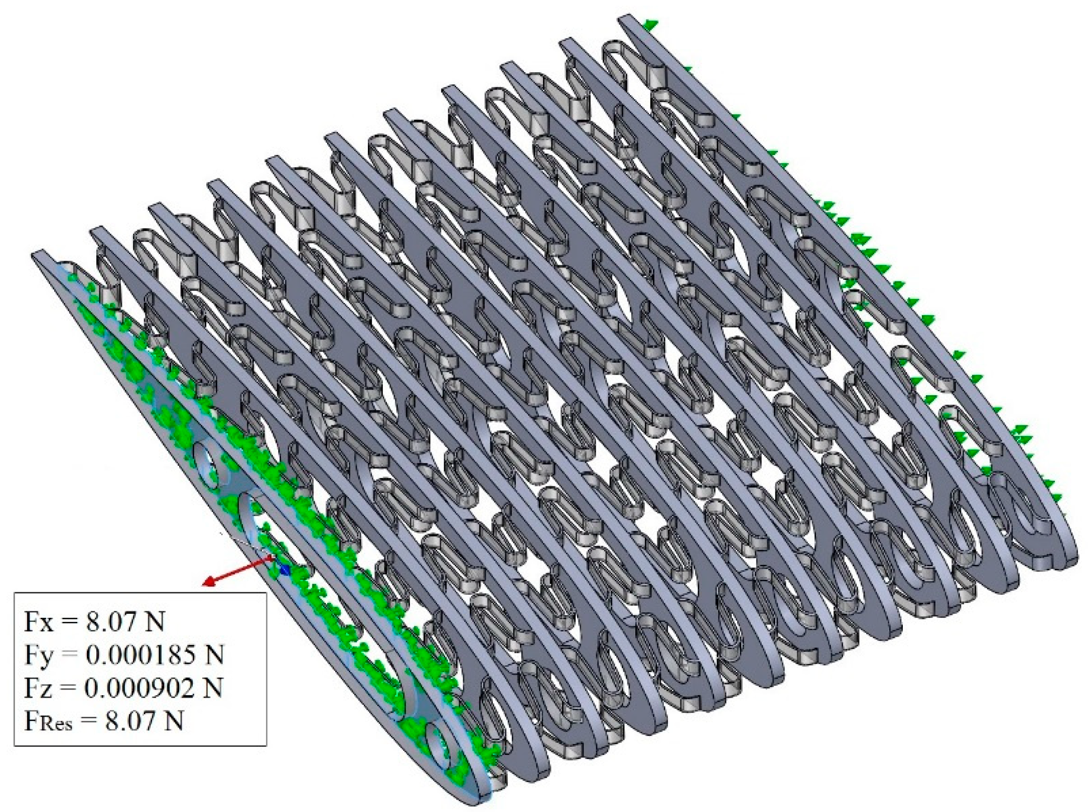
Multiple studies were also conducted on the honeycomb substructure. First, a static study was performed in order to find the force required to expand the honeycomb substructure through the full stroke. This was done to ensure that the linear actuators would be able to supply the force required to actuate the honeycomb substructure. One end of the honeycomb was fixed while the opposite end was given a 4 cm-prescribed displacement to expand or compress the structure. The reaction force in the direction of the actuation was found to be 8.05 N, which the linear actuators are more than capable of delivering (L12-R Actuonix Linear Electric Actuator [
20] provides 42 N output force).
Figure 8 displays the constraints of the honeycomb substructure in the FEA simulation, along with the prescribed displacements and reaction forces.
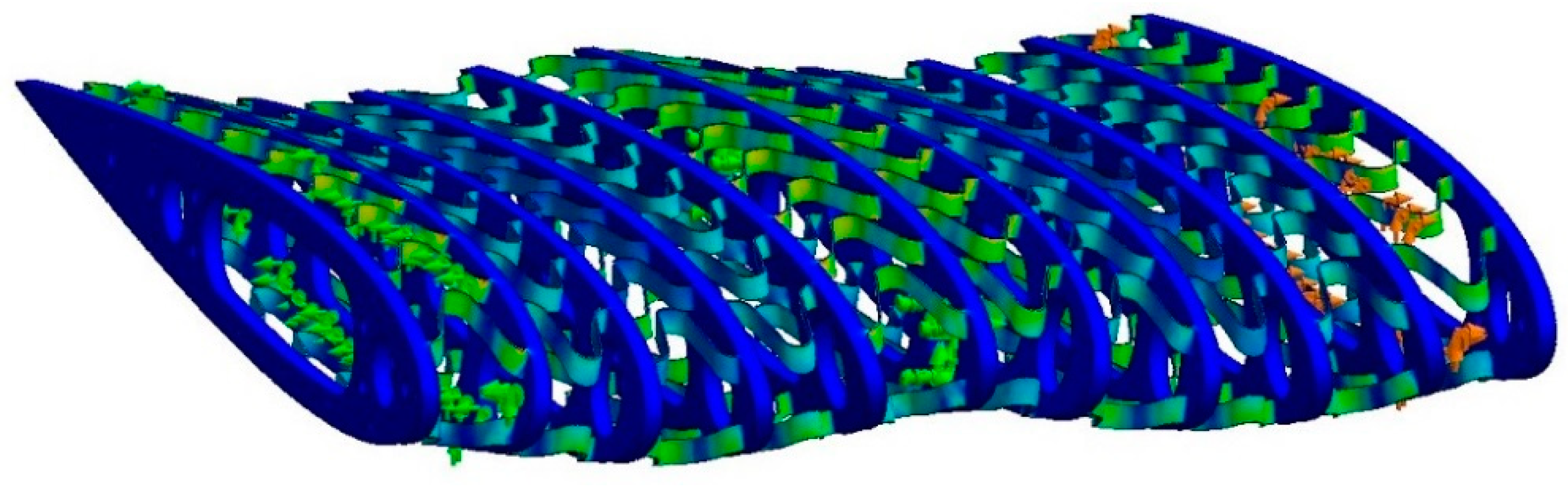
The honeycomb substructure and the internal ribs act as the main support for the skin of the wing. Hence, another study was conducted to check how the structure reacts to a large vertical load while in the extended configuration. The honeycomb was simulated by removing the spar supports to eliminate the rigid structure that would resist the vertical deflection. The magnitude of the vertical load was 100 N and was applied to the top half of the structure while a 4 cm-prescribed displacement was applied to the end of the honeycomb section. This large force was chosen to simulate an extreme situation, with a greater vertical load than the wing would experience in real life. One of the end ribs and the middle internal rib were fixed, simulating the honeycomb in the assembly.
The converged mesh that was used consisted of 1,077,564 nodes equivalent to 615,139 second-order tetrahedral elements, created using the curvature-based mesher in SOLIDWORKS Simulation. Despite the large vertical load, the maximum stress was well below the yield strength of Nylon Alloy 910, with a 5.3 minimum factor of safety. The maximum displacement was 4.5 mm. This means that the deformations of the chevrons will not interfere with the linear actuators or the internal spars.
Figure 9 shows the deformed and stressed structure.
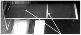
5. Testing
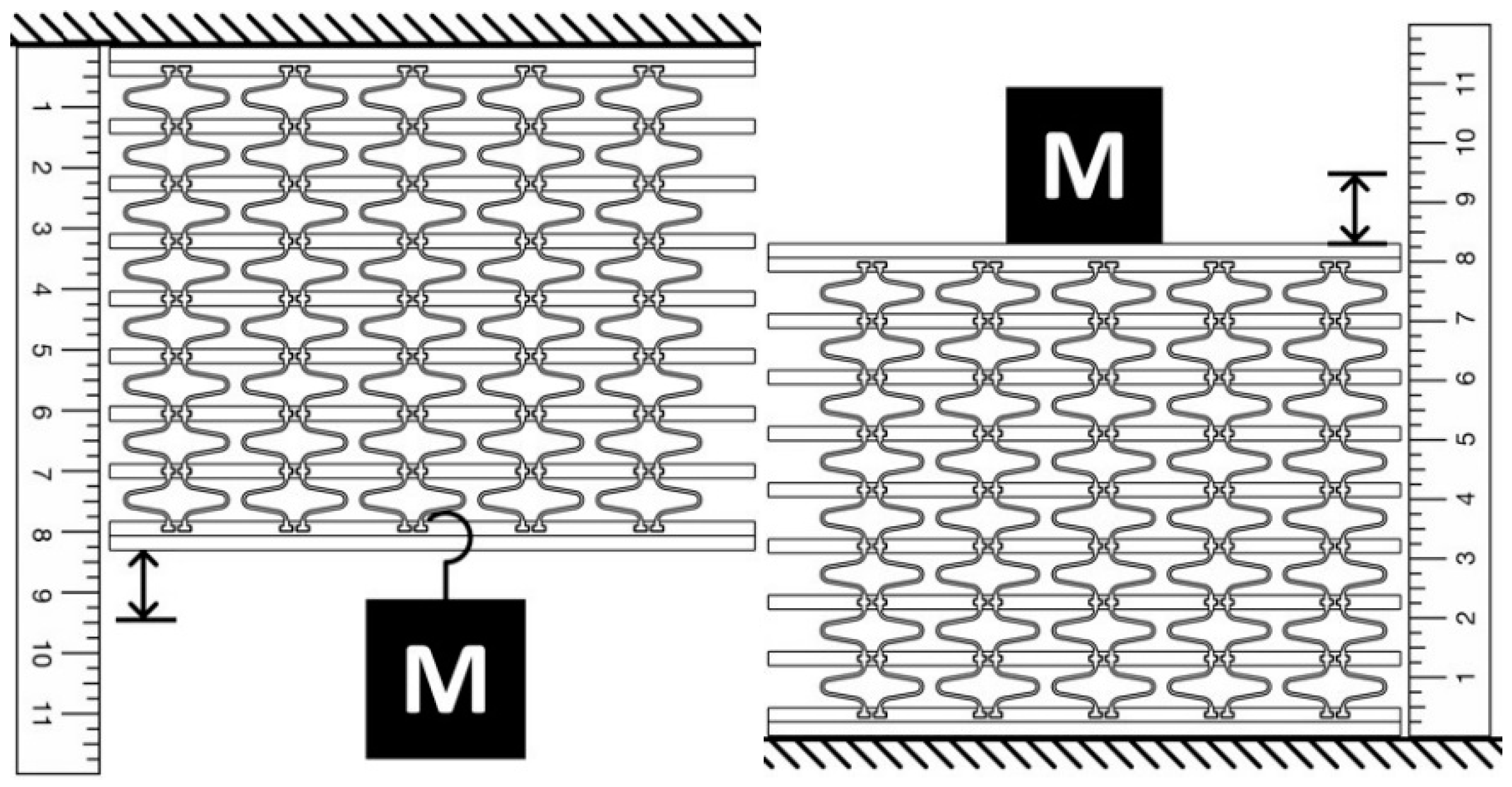
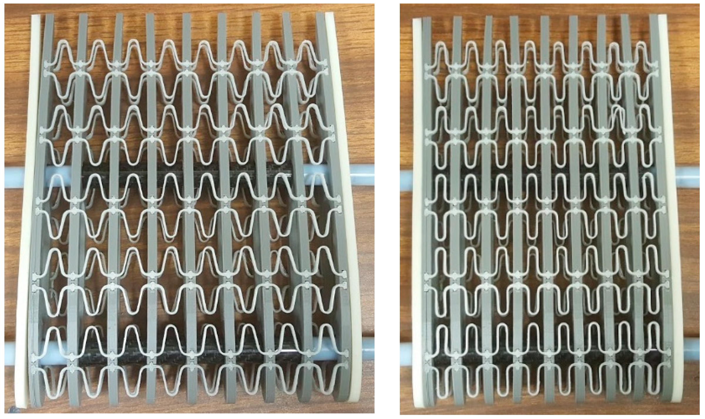
To test the spanwise compliance of the assembled partition, the structure was oriented with the ribs parallel to the floor, known weights were hung from the partition to induce extension, and the resulting displacements were measured. Similar tests were conducted with the partition under compression as shown in
Figure 11.
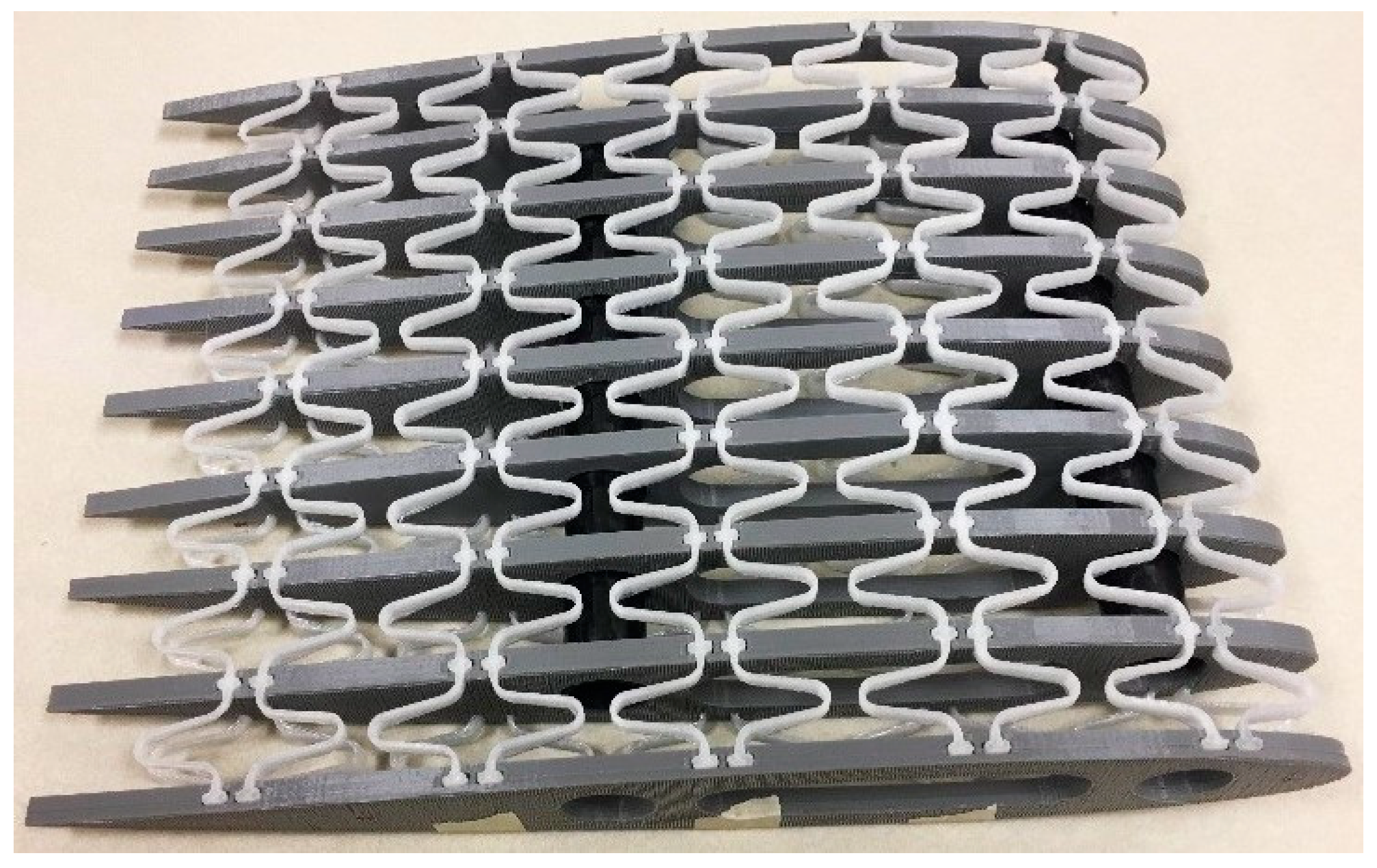
The span morphing partition is shown assembled and under compression in
Figure 12.
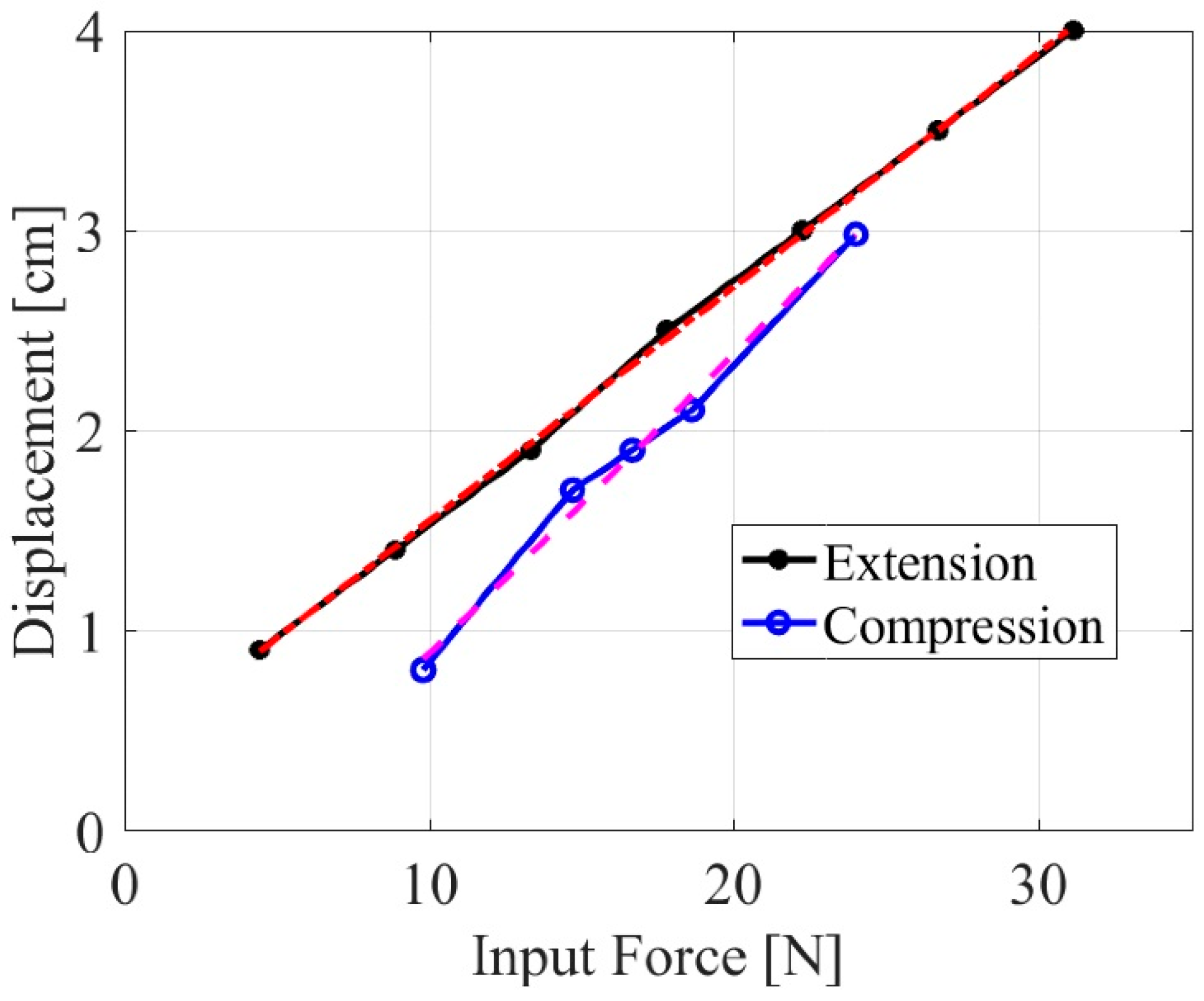
Figure 13 shows the results of the honeycomb compliance tests. The relation between displacement,
d, and input force,
F, was nearly linear in both cases, and can be expressed as
The stiffness of the honeycomb during extension was approximately 6.67 N/cm while the stiffness during compression was approximately 8.53 N/cm. Based on these experimental results, the geometry and the material of the chevrons can be iterated to accommodate any changing design requirements.
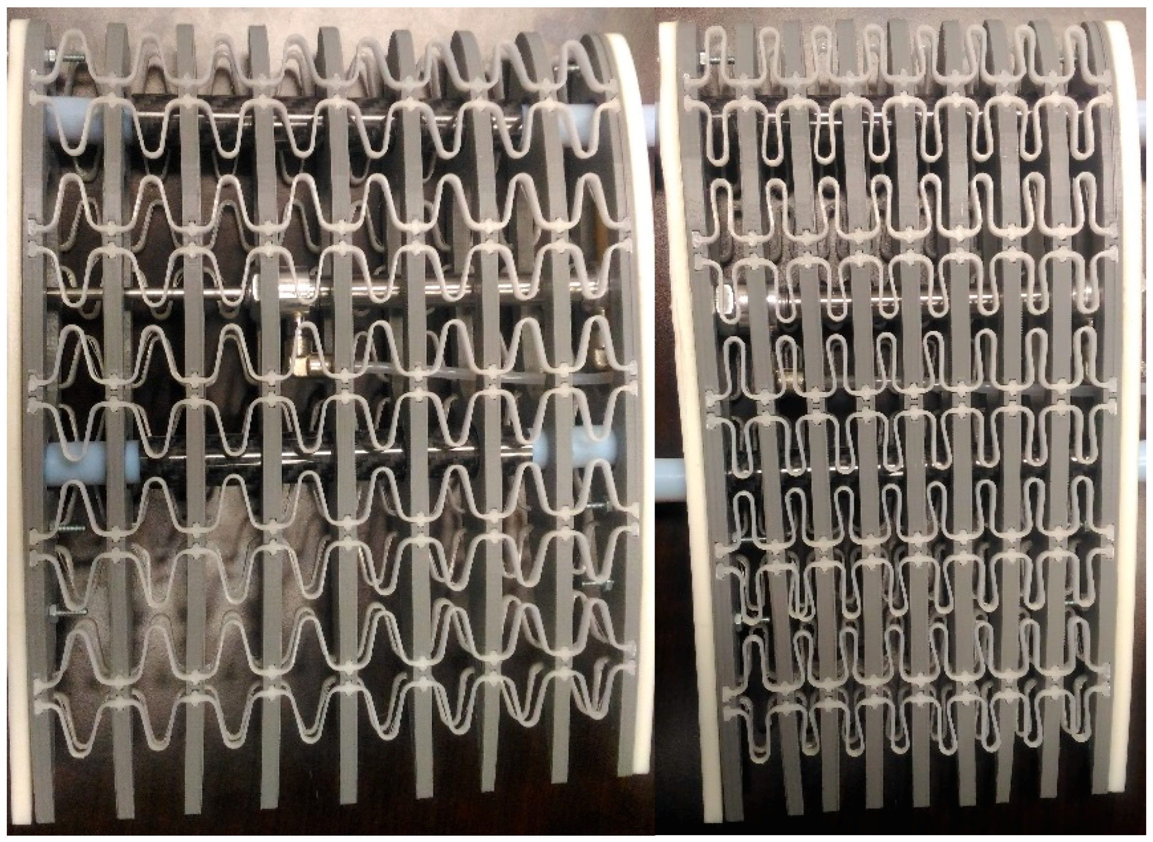
The linear actuators were able to fully extend and compress the manufactured wing partition smoothly, as shown in
Figure 14. Fixing one end rib of the wing partition in a horizontal position and hanging several weights on the opposite end rib, to induce bending moments equivalent to the expected aerodynamic bending loads, did not prevent the actuator from fully extending and compressing the model.
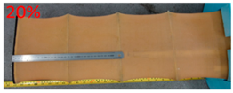
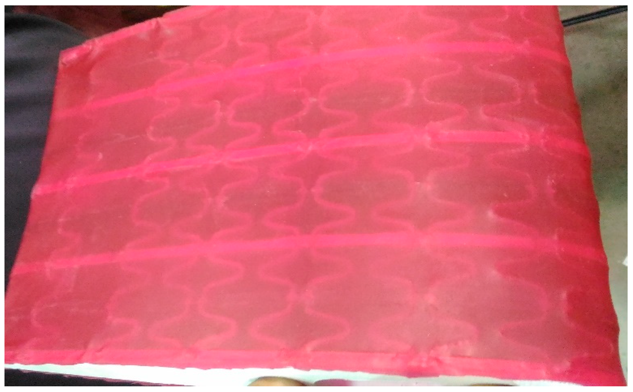
Current work is focusing on covering the proposed core design by a seamless pre-tensioned latex skin, as shown in
Figure 15, and performing wind tunnel tests. The skin is bonded to the internal ribs and will remain under tension in both actuation directions. This skin is the most suitable for the proposed design because when the wing section expands, the in-plane stiffness of the skin increases, allowing it to effectively transfer the applied aerodynamic loads to the ribs and spars. When the wing section contracts, the skin will remain under tension because of the applied pre-tension and the support of the chevrons and the internal ribs. The chevrons that are compressed between the internal ribs in this case will compensate for the decrease in skin stiffness by providing support to the skin.
6. Conclusions
This paper presented a new and improved design of a span-morphing UAV wing core model, where an assembled honeycomb substructure with interconnected telescoping spars and a linear actuator form one partition in a five-partition wing, able to make a fifty-percent span extension from a compressed configuration. The honeycomb substructure, made of rigid internal ribs with flexible chevrons, provides the necessary spanwise compliance to allow for actuation, and transverse rigidity to carry the aerodynamic loads, while maintaining the airfoil shape. The interconnected spars are the main load-carrying members in the design, and effectively enable the telescoping action to happen inside each partition of the wing. The linear actuators have the necessary output force to drive the system and can keep the partition at any desired configuration for any period of time. The new core is believed to have multiple advantages over previously published designs and improves the viability of a honeycomb-based span-morphing concept. The telescoping spar concept presented here resolves the drawbacks related to discontinuity and nonuniformity in the traditional telescoping wing designs, by bringing the telescoping mechanism inside the wing, rather than having it at the outer surface of the wing. This results in a seamless, continuous and uniform span-morphing wing. By separately 3D printing the internal ribs and chevrons of the honeycomb, different materials can be selected for the ribs and chevrons based on the design requirements, and components can be replaced easily during maintenance. Future work will focus on performing optimization studies on the wing with a stretchable skin, wind tunnel testing, failure analysis and reliability analysis.


