1. Introduction
With the rise of powerful information technology developed in the past few decades, obsolescence is a problem that is well-known to most people, evident every time the software of a smartphone outgrows its hardware. Obsolescence, the lack of suitability for desired use, describes the condition of objects, services, or practices when they are no longer able to meet changing requirements. These requirements range from new safety standards to users’ desires, but the cause of abandonment is largely irrelevant to its effect. Contrastingly, adaptability is the ability of an object to change to improve its functionality or suitability for a purpose. Viewed together, adaptable design can be leveraged as a tool for sustainability by reducing the occurrences of obsolescence.
Adaptability has great potential for application in the built environment, where the “demolition culture” found in the United States encourages a build-break philosophy. As noted by Lemer [
1], obsolescence poses a heavy burden on the owners and users of civil infrastructure. A study in Minnesota found that about 60% of all building demolitions are due to some type of obsolescence rather than reduced structural integrity [
2]. While this study was contained in St. Paul, there is no reason to believe that results would be different across the U.S; similar trends have been observed in other developed countries such as the U.K. [
3] and Japan [
4]. This high percentage of obsolescence-based demolitions suggests that the current way that our structures are designed is inadequate for meeting our long-term service needs. Structures are designed to last for hundreds of years but inhabitants cycle through structures about every 30 years [
5], causing more demolition and construction.
While accurately predicting (let alone planning) for the future is difficult, adaptability can be a tool for maintaining relevance. We can circumvent our unpreparedness by designing structures that are able to adapt to changing demands rather than continuing to build path-dependent structures based on static predictions.
1.1. Adaptability in Structures
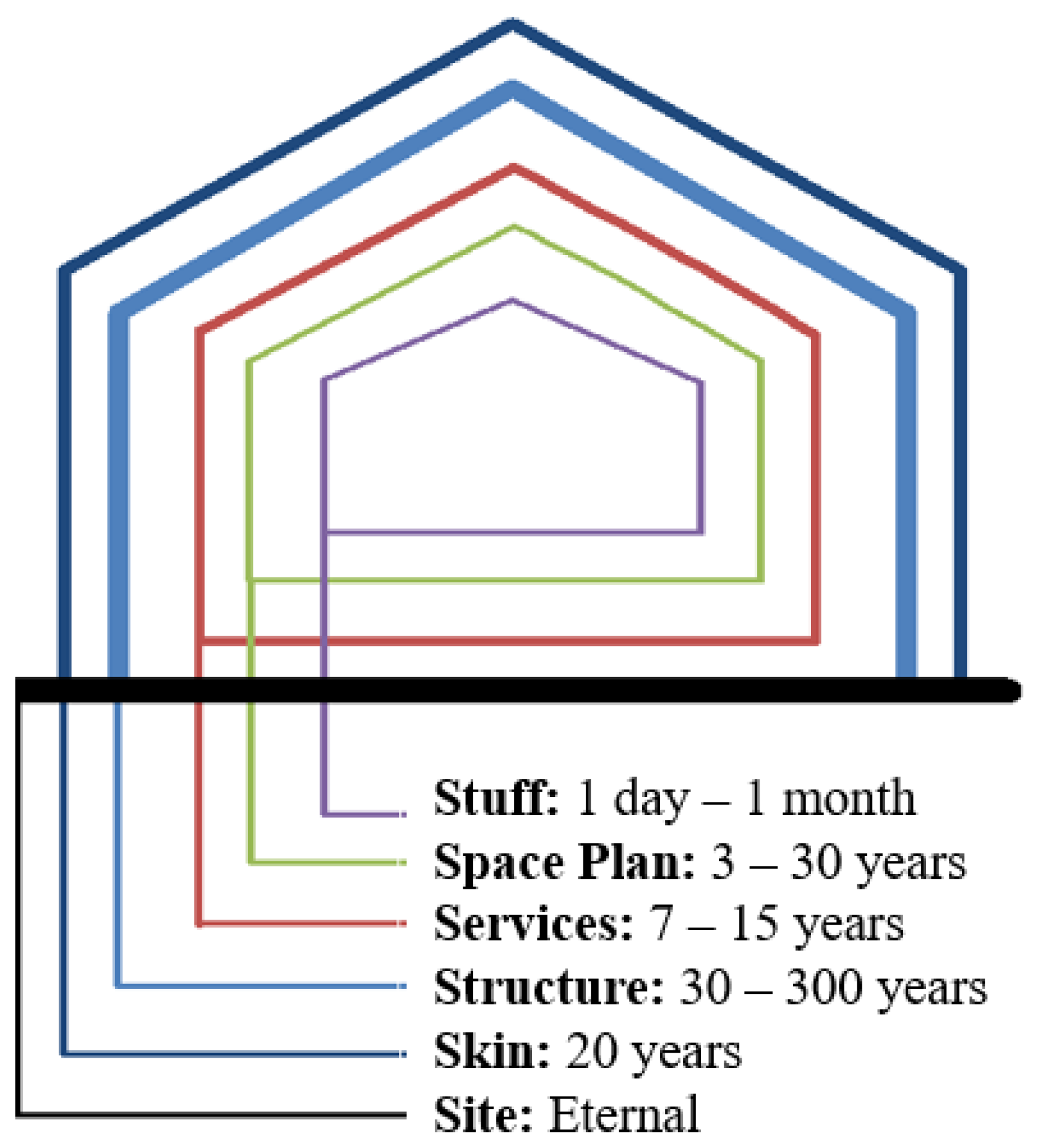
Adaptability in the built environment can be implemented on many levels to combat obsolescence. In his book,
How Buildings Learn, Stewart Brand describes six shearing layers of a building, based on the expected lifetime of each layer [
5]. These “six S’s” are shown in
Figure 1 with their typical lifetimes. Treating different layers as separate systems is significant for enabling adaptability in buildings, since this allows us to address different components of a building on its appropriate time scale. Let us consider one ludicrous example: if the skin layer were inseparable from the structural layer, a building would need to be torn down every time its paint color was changed.
A well-planned example of adaptability in structures is illustrated by the 2012 London Olympics, where the designers of the stadium arenas took possible future needs and uses of the site into consideration [
6]. The designers understood that the Games were a passing event and could result in an enormous waste of infrastructure and investment. Their plan was to convert the 80,000-seat stadium into a smaller-sized arena after the Games, and this was reflected in the use of temporary steel structures which allowed for partial disassembly. To allow for deconstruction, the stadium had a simple design with only two parts: a concrete bowl, and a lightweight steel truss structure that comprised the upper tiers and supported the roof membrane. Even details as small as connections were taking into consideration for component reuse and adaptability—bolts were used rather than welded steel connections. The foresight of the London Olympics designers in creating structures adaptable to changing demands ensured a prolonged life for both the site and the structures by taking the longstanding population’s needs into account.
While designing for adaptability may be more sustainable than succumbing to obsolescence, learning how to build adaptable structures is still a largely uncharted path. There have only been a handful of architectural designs and structural studies that use biomimicry [
7,
8,
9,
10,
11], and even fewer have examined adaptability in structures. Here is where we can turn to biomimicry for insight. Biomimicry, a design method that mimics Nature’s time-tested patterns and strategies, has potential for lessons in how to incorporate adaptability into structural design for a sustainable built environment.
1.2. Turning to Biomimicry and Engineering Systems for Adaptability Solutions
Biomimicry is a design method that draws inspiration from Nature for sustainable solutions to human challenges. Nature has 3.8 billion years’ worth of time-tested patterns and strategies, which engineers can and have learned from and applied. Janine Benyus, the modern popularizer of biomimicry, describes ten of “Nature’s principles”, referring to rules of thumb that natural systems follow [
12]. One principle,
form follows function, stands out as particularly relevant for adaptable infrastructure design. While this phrase is widely recognized as originating from modern, industrial architecture (20th century), this concept draws from the theory of evolution (e.g., as described by the overlap in Lamarck and Darwin’s theories in the 16th–17th centuries). Nature shapes its structural forms to help meet functional requirements, rather than adding more material and energy to produce similar outcomes [
12]. Natural structures are honed and polished through natural selection, resulting in systems that are effective, efficient, and multifunctional to meet each organism’s performance demands [
13].
This research considers Nature’s principle of
form follows function through an engineering lens by exploring biological systems through an engineering systems approach to better understand the mathematical functions underpinning natural forms [
14]. To describe the behavior of a system, a mathematical model called a
governing equation is often used [
15]. Governing equations are frequently taught as differential equations obtained by substituting a system’s constitutive relationships into more general laws of physics, such as Newton’s Second Law for mechanical systems and Kirchhoff’s Voltage and Current Laws for electrical systems. In classical mechanics, the dynamic motion of a system is characterized as a harmonic oscillator using three simple elements: a spring, a mass, and a damper. In electrical systems, capacitors, inductors, and resistors are directly analogous to the parameters for mechanical systems. Governing equations are also used in fluid flow and heat transfer, among other topics. The goal in discretizing various system types into fundamental parameters is to create simple models of complex systems, helping us to understand how systems’ inputs affect behavioral responses (e.g., system
functions transform the inputs into behavioral outputs—in this case, structural
form). This research asks biomimetic engineers, “If we’ve determined governing equations for mechanical systems, and governing equations for electrical systems, can we determine a governing equation (or at least the model elements) for adaptable systems?”
Users of biomimicry often function on the border of different disciplines, tools, and databases for connecting ideas for inspiration and application. As such, biomimicry is often a two-way street between biology and an engineering field. Biomimicry can be problem-driven, where engineers turn to biology in a search for sustainable solutions, or solution-driven, where scientists search for applications of their interesting discoveries [
16,
17]. In this paper, engineering mechanics is used to parameterize a problem-driven example—the adaptable growth of a spiraled seashell—to explore how biomimicry can be used for application to the design of adaptable structures.
2. Materials and Methods
This paper describes a biomimetic exploration of adaptability in a natural structure—the Turritella terebra, a spiraled turret shell that adapts its structure (its shell) to meet changing performance demands (mollusk growth). While “enlarging” is a simplistic form of growth, this project is an early attempt at characterizing adaptability in natural systems. The T. terebra grows by adding a layer of calcium carbonate to its newest edge, slowly incrementing its shell wall thickness and its overall helical length, which affects structural strength and behavior. The T. terebra was selected as the specimen for this study due to its simplicity, as well as its economical availability in large quantities for an experimental study. This structural engineering project investigates three parameters that may shed light on the adaptable growth of the shell: (1) the ratio of volumetric capacity to mass—dependent on wall thickness determined empirically; (2) the number of whorls (full revolutions of the shell)—investigated theoretically; and (3) the load capacity of the shell under three-point bending through the development of a finite element model of the T. terebra.
2.1. Shell Geometry and Model
The systematic study of seashells is dated as far back as 1838, when Moseley used a logarithmic spiral to describe their geometric form [
18]. Since Moseley, many others have improved the mathematical characterization of shell geometry through mathematical biology [
19], digital construction [
20], enhanced orthogonality of curves [
21], computational shell generation [
22], and the definition of three additional angles for more reliable modeling [
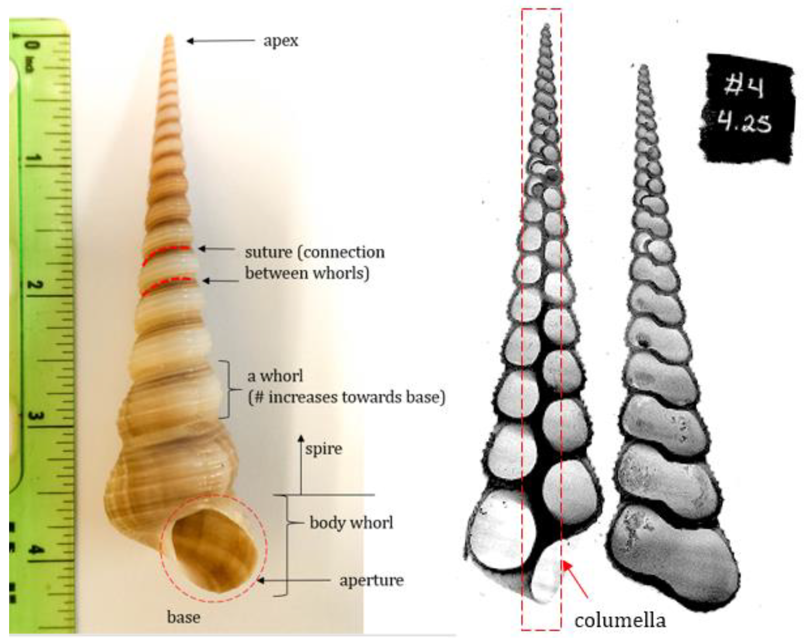
23]. The spiraled gastropod shell can be characterized throughout its taxonomic class using a set of geometric variables. These variables determine the form of the shell and include parameters such as vertical distance from the apex, radius of the helico-spiral, shape function of the aperture, and various expansion rates, among others. Basic shell terminology is illustrated in
Figure 2.
The gastropod shell is a composite material of calcium carbonate (in the form of calcite and/or aragonite) and organic macromolecules (e.g., proteins) [
24,
25]. As a reference point,
Table 1 shows the range of values for mechanical properties for the
Otala lactea (the Spanish snail, a related mollusk) as summarized by Rajabi et al. [
26]. Calcium carbonate has similar strengths to human-made building materials [
13] and can be considered in future studies of biomimicry to develop building materials with improved strength-to-weight ratios.
This section describes how a finite element (FE) model was created in order to run parametric studies on the
T. terebra. First, a 3D geometry of the shell was constructed in MATLAB to represent a shell specimen with approximately 19.75 whorls, a height of 5.4 inches, and base width of 1.4 inches [
27]. The 3D geometry of the shell is dependent on two angles (
and
, as shown in
Figure 3), an initial apex length R
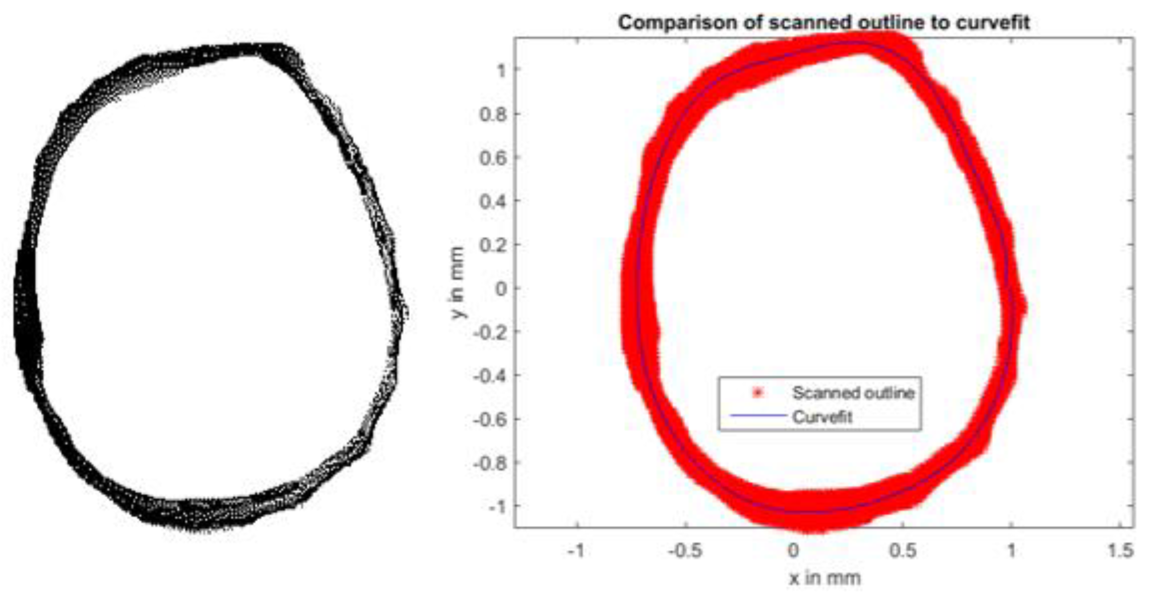
0, and the “generating curve” of the shell aperture. The generating curve of a particular specimen can be extracted from a cross-sectional image of the shell, and this 2D shape is then used as the template for creating whorls as they revolve around the columnella axis [
26,
28,
29]. To extract the outline, a simple code uses basic image processing techniques on a manually isolated aperture to determine the curve-fit function (see Reference [
27] for full code). The extracted generating curve from the shell specimen and its accompanying curve-fit used in the FE model are shown in
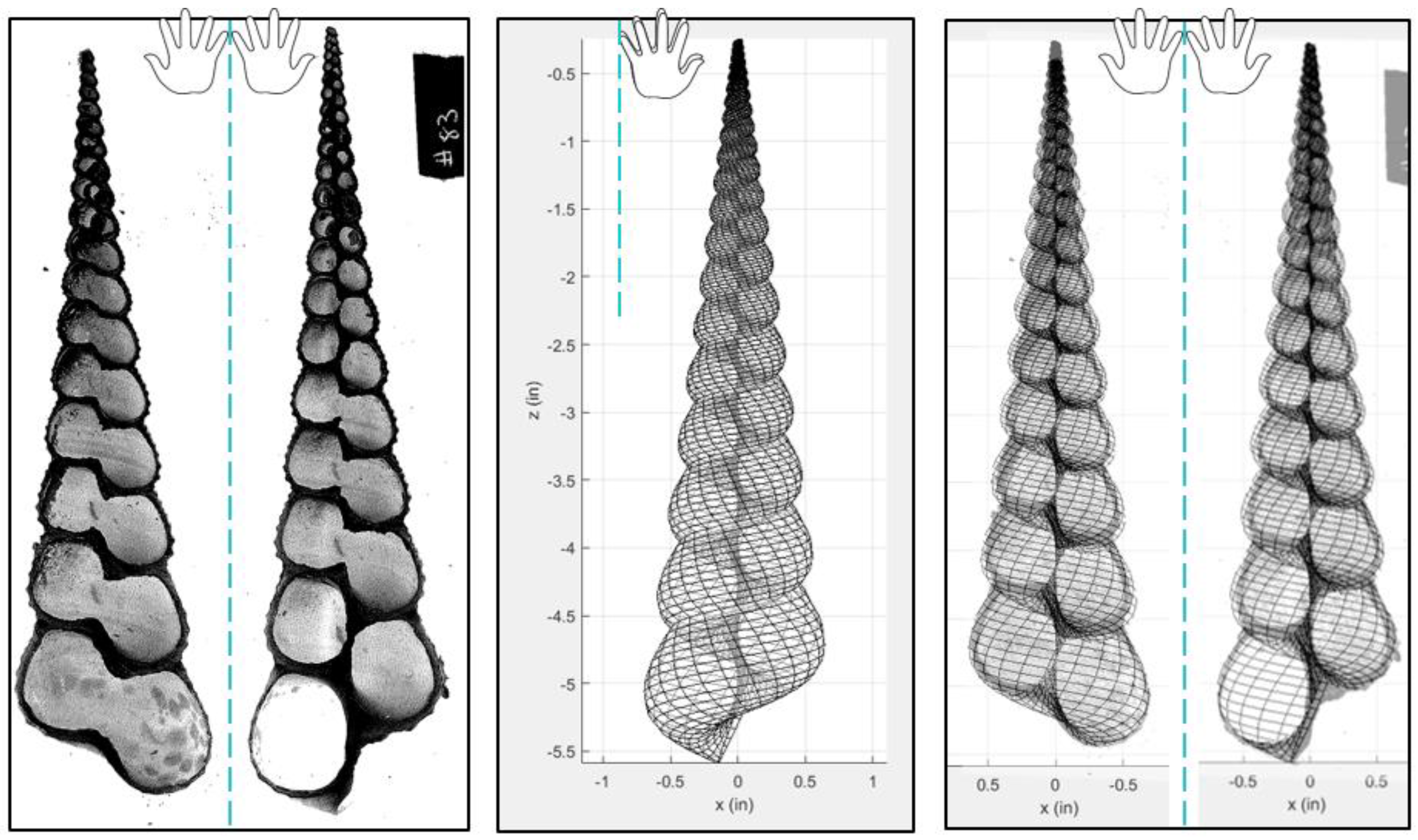
Figure 4. The resulting MATLAB geometry (combining the generating curve with
) is shown in
Figure 5 as a progression from its cross-sectional scan to its overlay with each geometrically modeled half.
The shell geometry, developed using Rajabi’s code [
26,
29], was then imported into ANSYS finite element software through direct generation to create nodes and shell elements [
30]. This model uses SHELL181 elements, the simplest version of the four-node shell element, with six degrees of freedom at each node. The structural FE model uses a Young’s modulus and Poisson’s ratio typical of mollusk shells,
[
26,
29,
31,
32]. The structural model was then subjected to simple three-point bending as the base approach for investigating adaptability through stress as a failure criterion. (Interested readers are directed to Reference [
27] for details of the FE model, such as constraints, boundary conditions, mesh convergence, comparison with experimental results, and treatment of numerical error.)
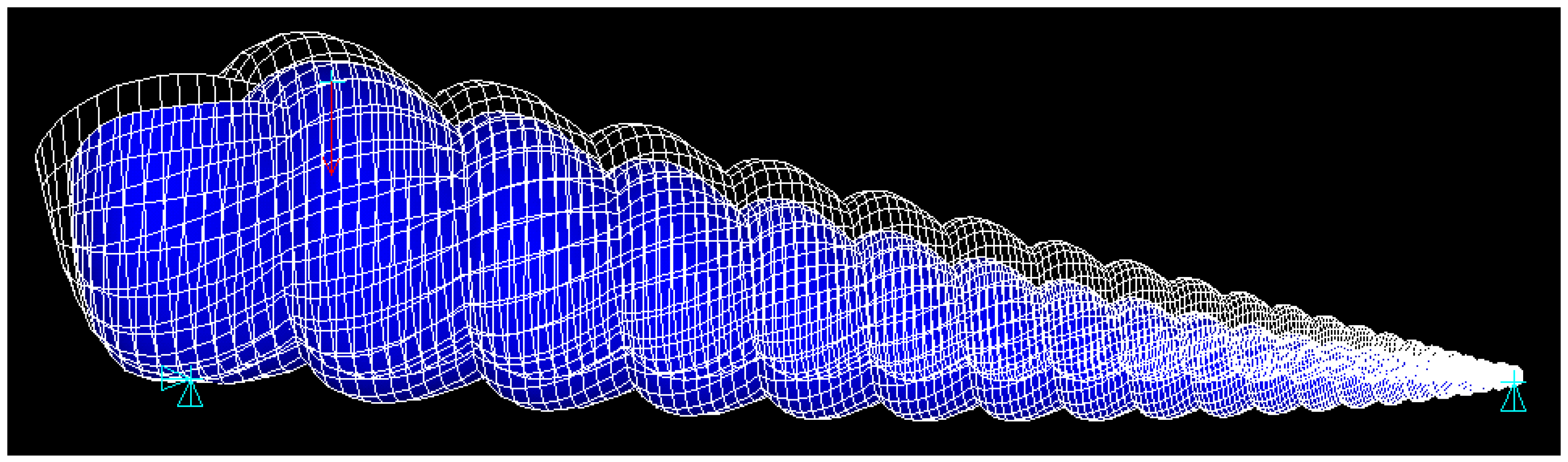
Figure 6 shows the typical deformation of the shell model in ANSYS as it undergoes three-point bending.
2.2. Parametric Studies
The structural model was developed as a means to explore parametric effects of growth on the shell’s adaptability. As shell growth was the primary form of adaptability investigated, parametric studies were designed around the method in which the shell added material to its structure. Here, three outcomes due to the addition of material are discussed: number of whorls as a characterization of shell maturity; optimization of living convenience for the mollusk; and impact on the tensile strength of the shell.
2.2.1. Number of Whorls
As the mollusk grows, it secretes a substance which solidifies at the edge of the shell aperture [
33]. This gradual deposition of primarily calcium carbonate sutures the current revolution to the previous shell section, creating a build-up of material and lengthening the spire over time. As such, the number of whorls increases with a shell’s maturity and was our proxy for characterizing shell age.
In experimental studies conducted on approximately 200
T. terebra specimens, a small collection (
n = 24) were cut into two longitudinal halves and their wall thicknesses were measured as a function of position along the columnella [
27]. This simple study corroborated that material is only deposited at the shell aperture, as smaller shells did not have thinner walls than their larger counterparts (both in terms of whorl count or absolute shell length).
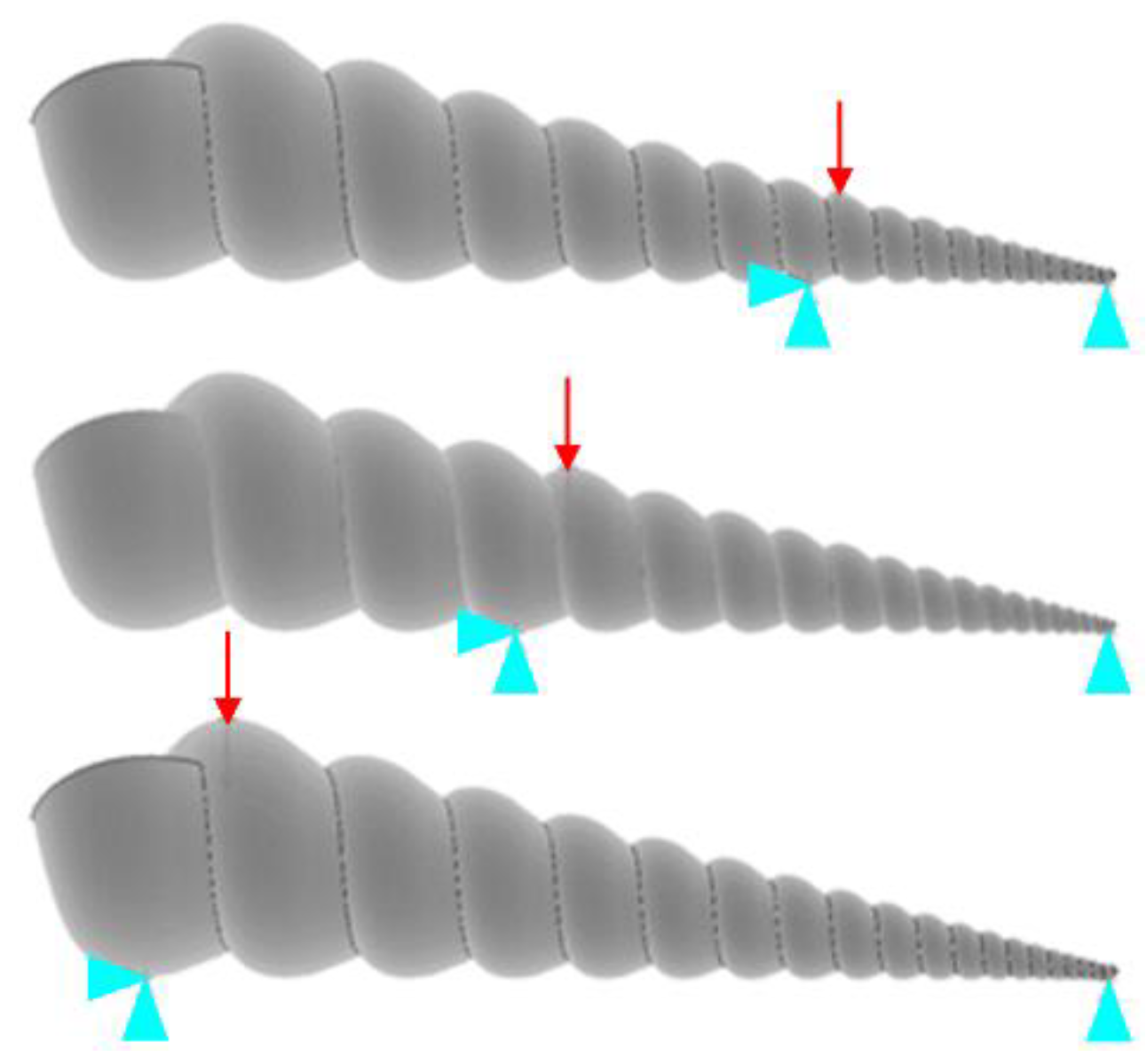
As each shell specimen has unique geometric variables, a control study where all constants but the number of whorls are identical is unfeasible. Instead, the number of whorls was parameterized in the model by simulating three-point bending on a section of the shell spire, as shown in
Figure 7. It should be noted that the effects of the cantilever base were negligible, as decreasing the material thickness of the cantilever to effectively zero (negating its stiffness and ensuring no force propagation) produced the same result as leaving it intact [
27], as per St. Venant’s principle regarding stresses distant from points of interest.
2.2.2. Living Convenience
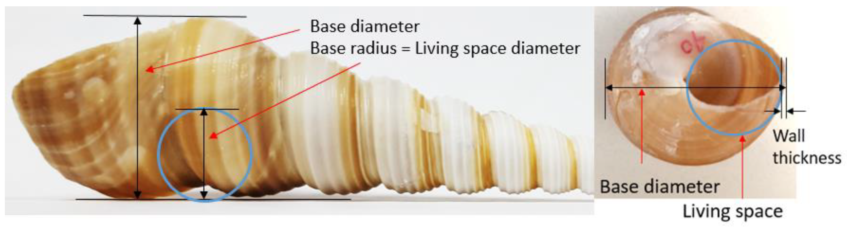
The thickness measurements described above did, however, increase as the shell’s diameter increased. Considering wall thickness from the mollusk’s perspective, we posit that the mollusk likely tries to maximize internal volume (the snail’s functional living space, with the shell being a physical constraint on its body), while minimizing shell weight. Wall thickness is inversely related to internal capacity, and directly related to the mass of the shell. Thus, the ratio of capacity to mass, renamed here as “living convenience”, is used as one variable in parametric analyses as thickness is systematically incremented. The internal living space is approximated as a sphere with a diameter half the width of the shell’s widest diameter, less its wall thickness (see
Figure 8). Mass was determined empirically in an experiment similar to wall thickness described above: shells of various sizes (
n = 22) were cut into segments along their spire, and these segments were weighed individually to determine a curve-fit equation for cumulative mass as a function of length.
2.2.3. Structural Capacity
Lastly, the parametric analysis examines how the shell’s addition of material affects its strength. In structural engineering, the phrase form follows function implies that the architecture (form) of a structure should support rather than detract from its structural integrity—the ability to keep a structure from failing in a crisis (function). One simple assessment of integrity is to examine the structure’s behavior under stress.
In three-point bending, brittle materials such as calcium carbonate typically experience tensile failure; hence, tensile strength was the failure criteria of interest for the shell FE model. The tensile strength typical of mollusk shells is 40.3 MPa (5845 psi) [
31], and when this value was exceeded at any location in the model, the shell was predicted to have fractured in real life. Typically, more material (e.g., thicker walls) enables structures to withstand higher loads, and this was found to be the case for the shell as wall thickness was incremented in the parametric analysis. (For details on how varying thickness was implemented in the FE model, see Reference [
27].)
Figure 9 illustrates the bottom surface of the shell under deformation (bending out of the page) and highlights the suture where fracture is predicted. This location matched the failure observed in physical tests of shells [
27].
As turret shells develop over time, they adapt and grow by depositing calcium carbonate to strengthen and lengthen their structure. The addition of material is considered through parametric analyses in two ways: (a) deposition at the aperture opening, slowly lengthening the spire as the shell matures; and (b) deposition in terms of wall thickness, which affects the shell’s volume, mass, and mechanical strength. Variations in percent thickness of the shell wall influence living convenience and load capacity (b), and these changes can be examined over time with shell maturity (a). Thus, it was determined that wall thickness is a significant variable in the shell’s adaptability. Incrementing thickness captures the shell’s changes in 3D space, as shown in
Figure 10.
The linear equation determined to best model wall thickness as a function of length was
where
t(
x) is the wall thickness, and
d(
x) is the diameter of the shell, in inches at any position
x along the columella. Equation 1 was developed from a series of measurements of
T. terebra shell segments in experimental studies [
27]. Incrementing wall thickness in parametric studies was performed by scaling the entire thickness equation by a factor in 5% increments, up to
. Because the study was interested in overall trends, increments of 5% were deemed to provide sufficient resolution for the parametric study; smaller increments would not have provided significant information to add to the overall trend. These varying thicknesses were implemented in the FE model, and the results of the model provided the corresponding load at which the shell fractured, as discussed in the next section.
3. Results
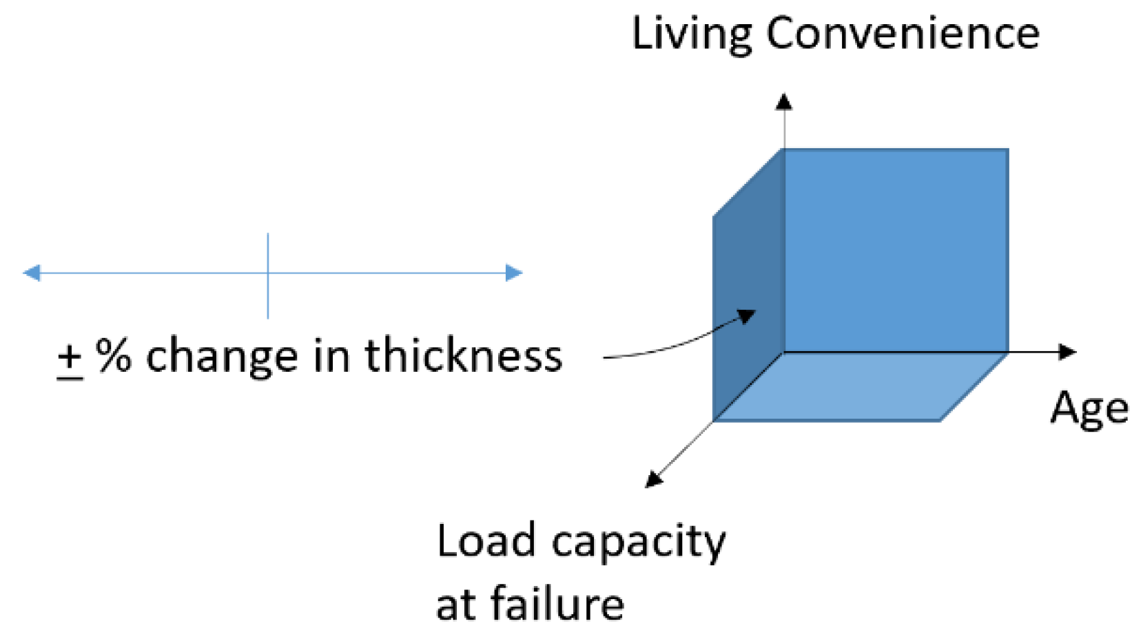
Results from the parametric studies are summarized in three figures below by presenting data as three separate planes, each with a pair of axes from
Figure 10. While the data in each graph are primarily governed by the
x- and
y-axis, the third parameter is illustrated as a color spectrum distributed across that variable’s full range. Furthermore, the incrementation of thickness is superimposed on each graph. The increments of ±5% wall thickness are indicated as a spectrum that follows the curve of the baseline thickness; percent changes are shown with red circular indicators, with the X’s representing the +20% change to help orient the reader. For example,
Figure 11 shows living convenience on the
y-axis, age (number of whorls) on the
x-axis, and failure load shown in color. The baseline thickness (0% change) is shown as a red line and can be seen in the center of the vertical spectrum as an asterisk.
Figure 11 shows that as thickness increases (moving towards red X), failure load increases and living convenience decreases while age is held constant.
Figure 11 shows that a mollusk’s living convenience increases as it grows—a shell with more whorls is more efficient at increasing its living space while keeping mass low. The colored contours in
Figure 11 illustrate the magnitude of the load that causes failure (a darker shade indicates a smaller load magnitude). It should be noted that the contour lines follow the load magnitudes, not the percent change in thickness. The shell is able to withstand larger loads as it gets older, which is simply a result of the boundary and loading conditions used in this model. As expected, by theoretically increasing wall thickness at any age, the shell decreases its chances for failure, but marginally loses some living convenience by doing so.
Figure 12 shows that as a shell adds more whorls, the load at which three-point bending failure occurs generally increases. In other words, older shells are more resistant to breaking than younger shells are, for the given boundary conditions. In
Figure 12, the contours illustrate the living convenience; the lighter colors indicate higher living convenience (i.e., high volumetric capacity to low mass). As expected, a decrease in thickness would both allow for more volumetric capacity and lessen total mass (thus, increased living convenience), but would also cause failure to occur more easily (at a smaller load magnitude). Interestingly, the failure load increases more steeply in youth and appears to stabilize after around 13–15 whorls, suggesting that immature shells are more intent on increasing their load capacity, and that there may be an upper limit to load capacity.
Figure 13 shows the relationship of load and living convenience as age changes. It is to be noted that the contours in this plot line up with the integer number of whorls. It appears that around 13–15 whorls, the rate of change drops off dramatically. In other words, after 13–15 whorls, the shell can increase its living convenience but can only gain a minimal increase in load capacity from its younger self. This is the same trend as seen previously: the young shell may be more intent on preventing fracture, while a larger shell spends energy on increasing its living convenience (suggesting that the shell may approach a limit of maximum strength). As demonstrated by the red symbols, a decrease in thickness corresponds to a lower load capacity but an increase in volumetric capacity to mass.
4. Discussion
This project examines a simplification of the T. terebra’s structural adaptability to growth over time. While direct parallels drawn to human structures are certainly fantastical (i.e., by no means do we suggest that buildings should be shaped like spiraled shells), the purpose of the comparisons made below is to demonstrate that connections can be found in Nature for engineering solutions. This study also provides a basic example of quantitative biomimicry through the use of structural modeling outside of its usual context.
4.1. Analysis of Shell Adaptability
As shown in
Figure 11, the mollusk may become more efficient at increasing living space while minimizing mass as it grows, but a simple thought experiment suggests that humans are not as efficient with their usable space. A common measurement of usable living space in real estate is the
floor area ratio, which the total floor area of a building (usable space across multiple stories) as a percent of its footprint. While the mollusk is able to capitalize on its internal capacity (volume approximated as a sphere), only floor
area is usable for humans. In real estate, the floor area ratio does not increase as ceilings are raised. Take a skyscraper for which every floor adds area
A and mass
m: its living space-to-mass ratio is essentially constant (
A/m), unlike the shell. If we consider volume, instead—in a direct comparison to the shell—we would find a similar increase in the living space-to-mass ratio as the height (number of floors) increases. However, as much of our vertical space is unused, this is best characterized as the space that requires heating or cooling [
34]. In contrast to the shell, this is an increasing relationship that we would like to
avoid, as it necessitates an increase in energy costs.
Figure 12 shows that older shells (more whorls) are able to resist larger loads than younger shells (fewer whorls); however, this is the opposite of what we observe in human structures. The geometries and structures of shells versus buildings are obviously very different, but the fact remains that our older structures are usually in a worse condition than newer ones. This is often due to poor upkeep or not meeting current standards, but ultimately structural health does not tend to improve with age. With regards to the shell’s length as a factor in resisting lateral loads, the simple analogy of building height can be made. Lateral loads on buildings (like wind) affect the behavior of tall skyscrapers more than shorter structures. The effect of changing wall thickness translates easily to buildings. Engineers could build thinner walls, but they would likely compromise structural integrity in the process. Similarly, walls that are overly thick interfere with internal occupant capacity.
In
Figure 13, we see that the change in slope of load capacity-to-living convenience alters dramatically after a certain number of whorls. This may suggest that the shell undergoes a transformation after which it spends its energy on different development activities. At a younger age, preventing fracture may be its focus, while after maturing and approaching a strength limit, the shell instead focuses on increasing living convenience. Based on commentary by Etter et al. [
35], the importance of size on survival may be separate from that of load capacity on survival, since we see that the shell does not stop growing as it approaches maximum load capacity. According to the Encyclopedia of Tidepools and Rocky Shores:
A larger size and thicker shell reduce the efficacy of shell-crushing predators such as crabs, fishes, and birds. For example, when crabs are provided with both thick- and thin-shelled prey, the thin-shelled morphs suffer much greater mortality because they are easier to break. Size is important because as snails increase in size, fewer predators can feed on them and they may often attain a size refuge, where they are sufficiently large that most predators are unable to consume them.
This change in the need for protection may explain the continuance of growth even after maximum load capacity is approached; increasing overall size may be more important than fracture strength after a certain age. A similar change in purpose can be considered for buildings—does vulnerability to certain hazards change with size, age, or other properties? If so, can we design for a mid-life transformation in performance demands?
4.2. Implications of Adaptability in Structural Design
The takeaway from this shell case study is not that we should design our buildings to look like shells. In order to utilize bio-inspiration as a practical tool, as designers we need to look past surface level aesthetics and examine the functions of the design. The spiraled turret shell was chosen as a simplified analogy to human structures, which also protect and house their inhabitants. As the shell grows, its adaptability for accommodating its inhabitant is crucial for its survival. The shell’s adaptability is the critical function examined in this paper—what can we learn from biomimetic adaptability to help our obsolescence-prone infrastructure?
As described in the introduction, while structural engineers are well-trained in considering structural integrity, designers do not often consider future use and structural adaptability to be a design parameter. This shell study provides some insight to structural designers into what we can consider during the design process for more sustainable infrastructure. Here, we present two ideas that reinforce the fact that planning must happen, even if only planning for the unknown, before construction is set in motion.
4.2.1. Planning Is Crucial for Adaptable Design
Shelled gastropods are born with a
protoconch, which is the initial part of the shell that develops as a coil in the embryo. This prenatal spiral sets the pattern for the shell’s growth to follow for the rest of its existence. This pattern is simple (defined by just a few parameters, as described in
Section 2.1), yet guided, leading to structured but unrestrained growth. This planning in advance to support future growth is not a concept we often consider in human structures. As designers, we need to think critically about how we can design structures to allow for the expansion that they will inevitably need, effectively designing the “prenatal” structure that supports future growth. For example, increasing occupancy numbers while maintaining access to natural light for occupants presents an interesting design challenge. If, in the future, we begin to build ad hoc vertical expansion out of necessity, how might we redesign structural components to be easily modified when an unknown number of floors could be added? These are questions that structural designers need to begin considering in the planning stages in order to set a path for growth, when working with what exists is a constraint, and demolition is no longer an option.
While there are on-going studies of adaptable design in human structures, practical implementation is currently rare. Ross et al. conducted a study to examine if there are particular design strategies that professionals perceive to enable adaptability more than others [
36]. Eleven strategies (see
Figure 14) were identified in the small but growing body of literature calling for an adaptable design paradigm. Fifteen design professionals were asked to rank, in their opinion, the importance of “adaptability enablers” such as the accuracy of drawings, open floor plans, and modular components. These “adaptability enablers”—factors that enable a structure to be adaptable to its occupants’ needs—provide insight into what the construction industry can focus on to prolong the lifetimes of structures.
One of the eleven parameters described in Ross’ work is
designing for adaptability and deconstruction (DfAD or DfD), a construction approach that emphasizes the importance of the design stage in considering the life cycle of structural components (rather than just their usefulness) [
37]. Ross posits that, even though DfD sounds like a promising technique, it may have received a low perceived effectiveness rating due to two factors. First, many of the other enablers overlap with design decisions made in DfD; and second, while some practicing engineers may consider the after-life implications of their designs, they may be unaware of DfD as a design framework, as it is not commonly applied in the United States [
36]. Both awareness and implementation of adaptable design are needed in the U.S., and turning to Nature to learn how to design adaptable structures may provide engineers with tools to better prevent obsolescence.
4.2.2. Planning Ahead Can Increase Efficiency
Cities may even be a better analogy for the spiraled gastropod shell than buildings. While buildings do not usually increase their efficiency with scale, cities do. For example, New York is the largest and, yet, most sustainable city in the United States [
38]. We actually see that an increase in population density increases infrastructural efficiency, since the physical components of infrastructure (e.g., cables, pipes, subways) have less absolute area to span. On the other hand, the urban sprawl of Los Angeles, caused by poor (or lack of) infrastructural planning, has stimulated wealth inequality between the urban center and suburbia at the fringe.
There is a long history, from Mumford (1961) [
39] to Batty (2013) [
40], of studying the form of human settlements. Recent work shows that some fundamental equations can be used to describe human behavior and efficiencies in these cities [
41]. For example, as cities grow, they require fewer resources per capita and produce more innovations per capita. While such research derives equations from the behavior of cities, this research hints at the potential to use equations to inform the design of cities. As seen in
Figure 11, the seashell grows in a way that is efficient for its occupant and also becomes more efficient as it grows. Well-planned urban areas grow in an analogous manner—as a city’s population grows, higher density commercial and residential structures tend to be constructed, leading to more living space for less material, like the shell achieves. Studying Nature’s adaptable structures for hidden yet practical lessons can inspire us to design and help us to plan for structures and infrastructure that support our growing population.
5. Conclusions
This research explores biomimicry as a design approach for reimagining our building philosophy to disrupt the current obsolescence-demolition culture. By turning to Nature, engineering systems and quantitative analysis techniques can lead us to an understanding of how complex systems work, and we may be able to discover fundamental model elements that affect adaptable behavioral response.
In this paper, the structural adaptability of the T. terebra spiraled turret shell is investigated through finite element modeling and parametric studies. The shell is able to change its structure over time to meet changing performance demands—a feat of adaptability that could transform our current infrastructure design if implementable. Based on the results of the parametric studies, two design applications are provided. First, we emphasize that the planning stage in the design process is crucial. Current implementation of adaptability in the structural design process is rare; moreover, parallel work in civil engineering has found that adaptable design is misunderstood and underutilized effectively. Turning to Nature for biomimetic lessons in adaptability may help us better identify the critical design parameters that lead to adaptability. Second, analogies are also drawn between the shell’s adaptability and city design. Our city planners can learn from the adaptable growth of the shell to more effectively manage population and infrastructural growth. By planning ahead strategically, our cities are capable of increasing infrastructural efficiency as boundaries and populations expand, much like the shell.
While shell and human structures are incommensurable, especially given the assumptions, approximations, and simplicity of the shell model, the purpose of these analogies is to demonstrate that the challenges that we face as engineers may resemble those already resolved in Nature. While we may not have the step-by-step answers to how to design adaptable buildings yet, we show readers that adaptable structures are possible, as demonstrated by the shell. Recent work has begun the search for adaptability blueprints, but more effective solutions might be found through further biomimetic studies. We encourage readers to consider biomimicry as a source of inspiration for their own research and hope that this work will incite collaboration between disciplines, as natural forms do not conform to artificial disciplinary boundaries. Some of the largest opportunities for scientific advances lie at the convergence of multiple disciplines [
42,
43,
44], and applying biomimicry to structural forms can place structural engineers at the cutting edge of these advances.
Author Contributions
Conceptualization, D.A.C.; Methodology, D.A.C.; Software, D.A.C.; Validation, D.A.C., Formal Analysis, D.A.C.; Investigation, D.A.C.; Resources, D.A.C. and B.E.R.; Data Curation, D.A.C.; Writing—Original Draft Preparation, D.A.C.; Writing—Review and Editing, D.A.C., B.E.R., and L.E.K.; Visualization, D.A.C.; Supervision, B.E.R. and L.E.K.; Project Administration, DA.C.; Funding Acquisition, B.E.R. and L.E.K.
Funding
This research has been performed in part using funding received from the Department of Education Graduate Assistance in Areas of National Need program (Award number P200A12022).
Acknowledgments
The authors thank Hamed Rajabi and his research team for their magnanimous support of this PhD project through their generous contribution of MATLAB code for shell geometry generation.
Conflicts of Interest
The authors declare no conflict of interest.
References
- Lemer, A. Infrastructure Obsolescence and Design Service Life. J. Infrastruct. Syst. 1996, 2, 153–161. [Google Scholar] [CrossRef]
- The Athena Institute. Minnesota Demolition Survey: Phase Two Report; Prepared for: Forintek Canada Corp; The Athena Institute: Kutztown, PA, USA, 2004. [Google Scholar]
- DTZ Consulting. Demolition and New Building on Local Authority Estates; U.K. Department of the Environment, Transport and the Regions: London, UK, 2000. [Google Scholar]
- Yashiro, T.; Kato, T.; Yoshida, T.; Komatsu, Y. Survey on Real Life Span of Office Buildings in Japan. In Proceedings of the CIB 90 W55/65 Symposium; University of Technology: Sydney, Australia, 1990; pp. 215–226. [Google Scholar]
- Brand, S. How Buildings Learn: What Happens after They’re Built; Penguin Books: New York, NY, USA, 1995; ISBN 0140139966. [Google Scholar]
- Abrahams, T. London 2012—Olympic Stadium (29 April 2014, pp. 744–753). Available online: https://www.detail-online.com/article/london-2012-olympic-stadium-16402/ (accessed on 5 May 2015).
- Claggett, N.; Surovek, A.; Capehart, W.; Shahbazi, K. Termite Mounds: Bioinspired Examination of the Role of Material and Environment in Multifunctional Structural Forms. J. Struct. Eng. 2018, 144, 2518001. [Google Scholar] [CrossRef]
- Biomimicry Institute Termite-Inspired Air Conditioning 2014. Available online: http://biomimicryinstitute.org/case-studies/case-studies/termite-inspired-air-conditioning.html (accessed on 10 February 2014).
- Meyers, M.A.; Chen, P.-Y.; Lin, A.Y.-M.; Seki, Y. Biological materials: Structure and mechanical properties. Prog. Mater. Sci. 2008, 53, 1–206. [Google Scholar] [CrossRef]
- Horwitz-Bennett, B. Biomimicry: Nature’s Lessons—Design Echoes Natural Life with the Science of Biomimicry. 2009. Available online: https://www.interiorsandsources.com/article-details/articleid/6984/title/biomimicry-nature-s-lessons (accessed on 10 February 2014).
- Bojovic, M. Honeycomb Facade for Softer Urban Landscape/Sinosteel, Tianjin by MAD Architects. eVolo, 26 March 2013. [Google Scholar]
- Nature’s Unifying Patterns: 10 Lessons to Consider Every Time You Design Something. Available online: http://toolbox.biomimicry.org/wp-content/uploads/2015/01/Natures_Patterns.pdf (accessed on 8 December 2015).
- Chen, D.A.; Ross, B.E.; Klotz, L.E. Lessons from a Coral Reef: Biomimicry for Structural Engineers. J. Struct. Eng. 2014, 14, 02514002. [Google Scholar] [CrossRef]
- Chen, D.A.; Klotz, L.E.; Ross, B.E. Mathematically Characterizing Natural Systems for Adaptable, Biomimetic Design. Procedia Eng. 2016, 145, 497–503. [Google Scholar] [CrossRef]
- Cha, P.D.; Molinder, J.I. Fundamentals of Signals and Systems with CD-ROM: A Building Block Approach; Cambridge University Press: Cambridge, UK, 2006; ISBN 978-0-521-84966-1. [Google Scholar]
- Helms, M.E.; Vattam, S.S.; Goel, A.K.; Yen, J.; Weissburg, M. Problem-Driven and Solution-Based Design: Twin Processes of Biologically Inspired Design. In Proceedings of the 28th Annual Conference of the Association for Computer Aided Design in Architecture, Minneapolis, MN, USA, 16–19 October 2008; Association for Computer Aided Design in Architecture: Minneapolis, MN, USA, 2008. [Google Scholar]
- Badarnah, L.; Kadri, U. A methodology for the generation of biomimetic design concepts. Archit. Sci. Rev. 2015, 58, 120–133. [Google Scholar] [CrossRef]
- Moseley, H. On the Geometrical Forms of Turbinated and Discoid Shells. Philos. Trans. R. Soc. Lond. 1838, 128, 351–370. [Google Scholar] [CrossRef]
- Thompson, D.W. On Growth and Form; Cambridge University Press: Cambridge, UK; Macmillan: New York, NY, USA, 1945. [Google Scholar]
- Raup, D.M. The Geometry of Coiling in Gastropods. Proc. Natl. Acad. Sci. USA 1961, 47, 602–609. [Google Scholar] [CrossRef] [PubMed]
- Illert, C. Formulation and solution of the classical seashell problem. Il Nuovo Cimento D 1989, 11, 761–780. [Google Scholar] [CrossRef]
- Cortie, M. Models for mollusc shell shape. S. Afr. J. Sci. 1989, 85, 454–460. [Google Scholar]
- Fowler, D.R.; Meinhardt, H.; Prusinkiewicz, P. Modeling seashells. ACM SIGGRAPH Comput. Graph. 1992, 26, 379–387. [Google Scholar] [CrossRef]
- Neves, N.M.; Mano, J.F. Structure/mechanical behavior relationships in crossed-lamellar sea shells. Mater. Sci. Eng. C 2005, 25, 113–118. [Google Scholar] [CrossRef]
- Chen, P.-Y.; McKittrick, J.; Meyers, M.A. Biological materials: Functional adaptations and bioinspired designs. Prog. Mater. Sci. 2012, 57, 1492–1704. [Google Scholar] [CrossRef]
- Rajabi, H.; Darvizeh, A.; Shafiei, A.; Eshghi, S.; Khaheshi, A. Experimental and numerical investigations of Otala lactea’s shell–I. Quasi-static analysis. J. Mech. Behav. Biomed. Mater. 2014, 32, 8–16. [Google Scholar] [CrossRef] [PubMed]
- Chen, D. The Adaptable Growth of Seashells: Informing the Design of the Built Environment through Quantitative Biomimicry. Ph.D. Thesis, Clemson University, Clemson, SC, USA, 2016. [Google Scholar]
- Jirapong, K.; Krawczyk, R.J. Case Study: Modeling the Interior Structure of Seashells; University of Granada: Granada, Spain, 2003. [Google Scholar]
- Faghih Shojaei, M.; Mohammadi, V.; Rajabi, H.; Darvizeh, A. Experimental analysis and numerical modeling of mollusk shells as a three dimensional integrated volume. J. Mech. Behav. Biomed. Mater. 2012, 16, 38–54. [Google Scholar] [CrossRef] [PubMed]
- ANSYS Mechanical APDL Modeling and Meshing Guide (Release 15.0). 2013. Available online: https://pdfs.semanticscholar.org/db34/6925ddc8a17ab7a3e5ef6c3f26517f4a4047.pdf (accessed on 3 February 2014).
- Currey, J.D. Further studies on the mechanical properties of mollusc shell material. J. Zool. 1976, 180, 445–453. [Google Scholar] [CrossRef]
- Currey, J.D.; Taylor, J.D. The mechanical behaviour of some molluscan hard tissues. J. Zool. 1974, 173, 395–406. [Google Scholar] [CrossRef]
- Hutchinson, J.M.C. Control of gastropod shell shape; The role of the preceding whorl. J. Theor. Biol. 1989, 140, 431–444. [Google Scholar] [CrossRef]
- Cabello Matud, C. Repercusión Arquitectónica del Volumen de las Instalaciones en los Edificios de Oficinas: Análisis de las Instalaciones de Aire Acondicionado. Ph.D. Thesis, Universitat Politècnica de Catalunya, Barcelona, Spain, 2016. [Google Scholar]
- Etter, R.; Denny, M.W.; Gaines, S.D. Snails. In Encyclopedia of Tidepools and Rocky Shores; University of California Press: Oakland, CA, USA, 2007; pp. 530–536. ISBN 978-0-520-25118-2. [Google Scholar]
- Ross, B.E.; Chen, D.A.; Conejos, S.; Khademi, A. Enabling Adaptable Buildings: Results of a Preliminary Expert Survey. Procedia Eng. 2016, 145, 420–427. [Google Scholar] [CrossRef]
- Webster, M.D. Structural Design for Adaptability and Deconstruction: A Strategy for Closing the Materials Loop and Increasing Building Value; American Society of Civil Engineers: Reston, VA, USA, 2007; pp. 1–6. [Google Scholar]
- Cohen, S.; Richard, M.G. New York City: Sustainable City? Available online: http://www.treehugger.com/travel/new-york-city-sustainable-city.html (accessed on 19 July 2016).
- Mumford, L. The City in History: Its Origins, Its Transformations, and Its Prospects; Houghton Mifflin Harcourt: Boston, MA, USA, 1961; ISBN 978-0-15-618035-1. [Google Scholar]
- Batty, M. The New Science of Cities; MIT Press: Cambridge, MA, USA, 2013; ISBN 978-0-262-01952-1. [Google Scholar]
- Bettencourt, L.M.A.; Lobo, J.; Helbing, D.; Kühnert, C.; West, G.B. Growth, innovation, scaling, and the pace of life in cities. Proc. Natl. Acad. Sci. USA 2007, 104, 7301–7306. [Google Scholar] [CrossRef] [PubMed]
- National Research Council; Committee on Key Challenge Areas for Convergence and Health; Board on Life Sciences; Division on Earth and Life Studies. Convergence: Facilitating Transdisciplinary Integration of Life Sciences, Physical Sciences, Engineering, and Beyond; The National Academies Press: Washington, DC, USA, 2014. [Google Scholar]
- Bermejo-Busto, J.; Martín-Gómez, C.; Zuazua-Ros, A.; Baquero, E.; Miranda, R. Performance simulation of heat recovery ventilator cores in cascade connection. Energy Build. 2017, 134, 25–36. [Google Scholar] [CrossRef]
- Zuazua-Ros, A.; Martín-Gómez, C.; Ramos, J.C.; Gómez-Acebo, T. Bio-inspired Heat Dissipation System Integrated in Buildings: Development and Applications. Energy Procedia 2017, 111, 51–60. [Google Scholar] [CrossRef]
© 2018 by the authors. Licensee MDPI, Basel, Switzerland. This article is an open access article distributed under the terms and conditions of the Creative Commons Attribution (CC BY) license (http://creativecommons.org/licenses/by/4.0/).


