Parametric Study of the Behavior of Longitudinally and Transversally Prestressed Concrete under Pure Torsion


Abstract
:
1. Introduction
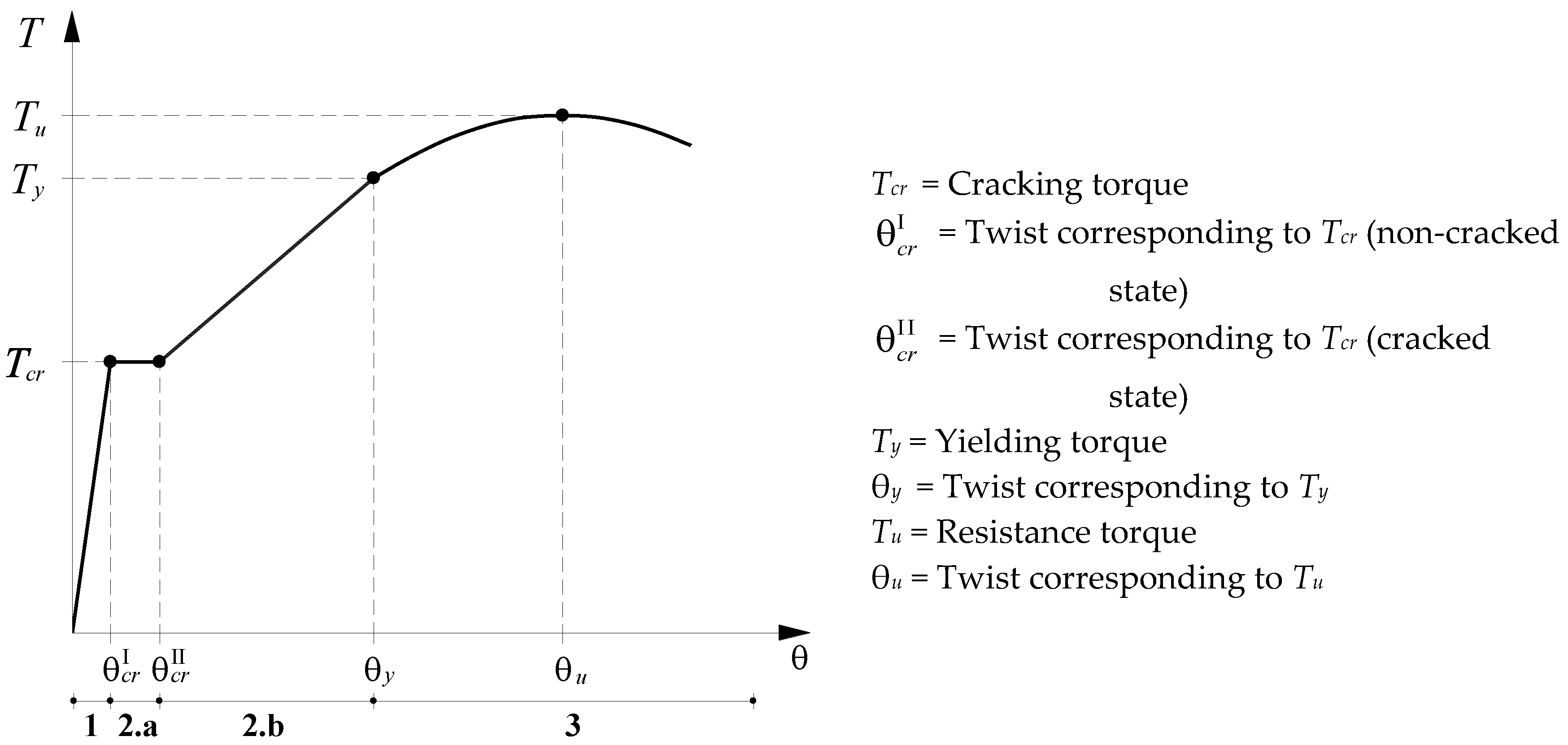
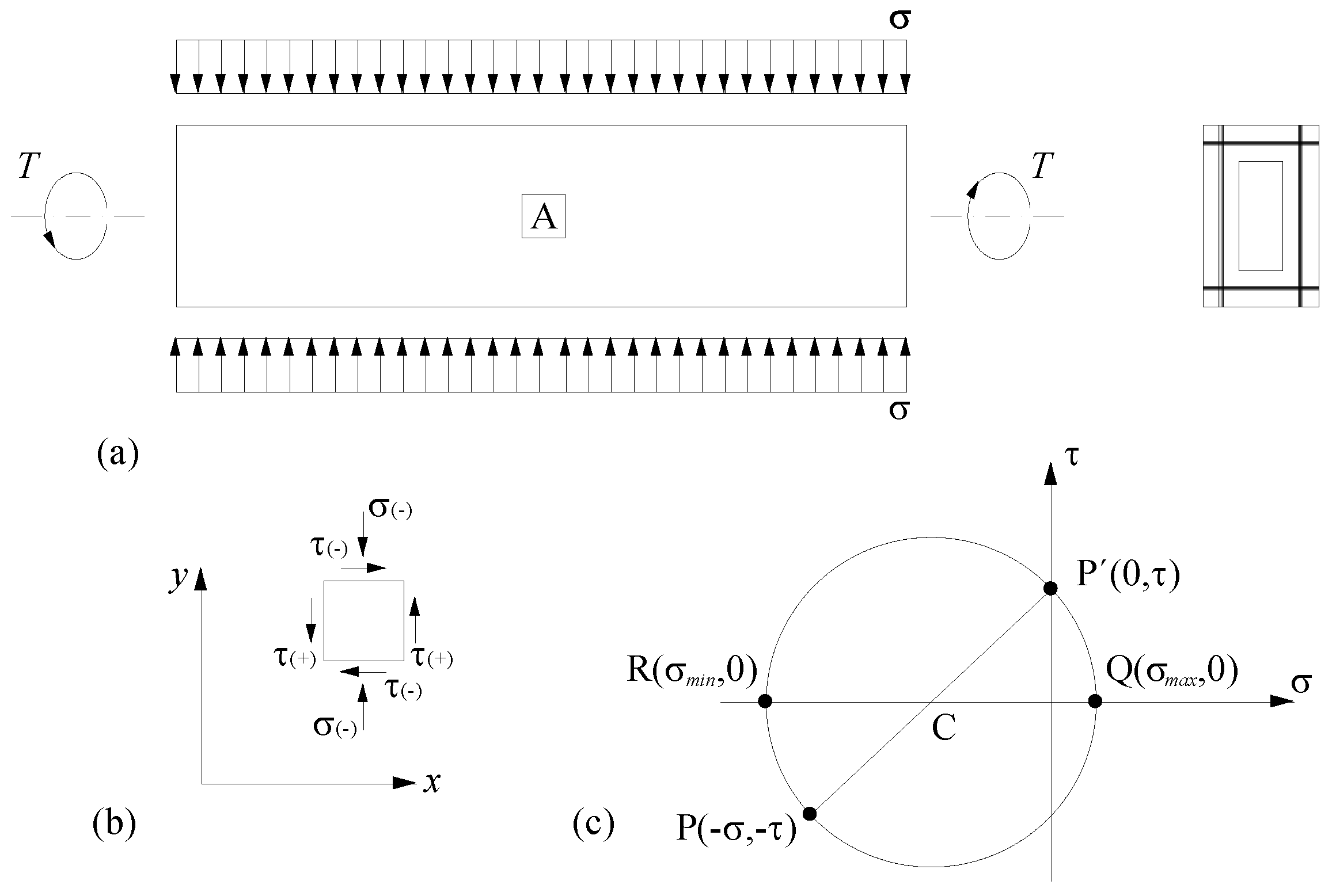
2. Modified Variable Angle Truss Model (MVATM)
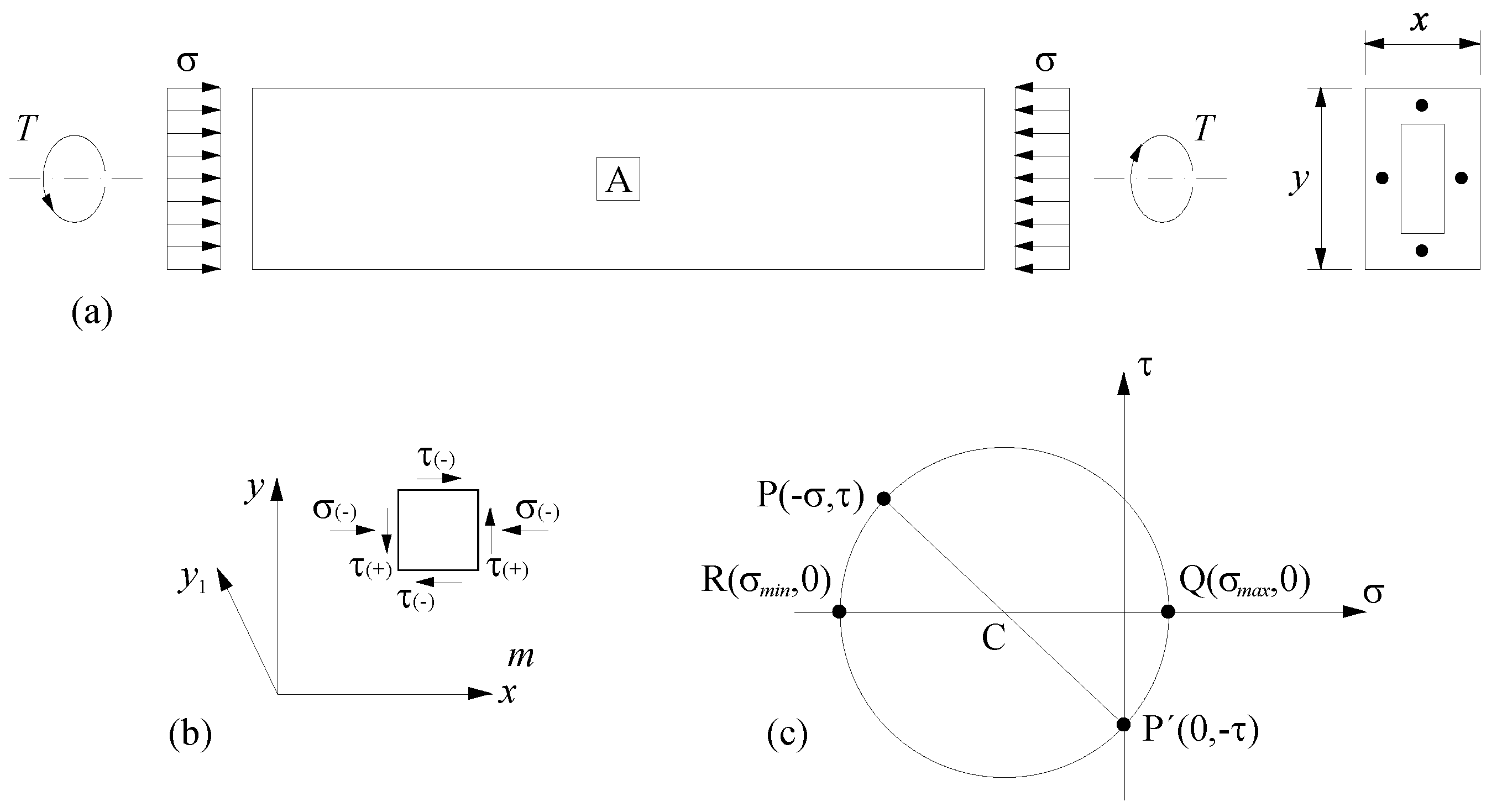
2.1. Non-Cracked State
2.2. Cracked State
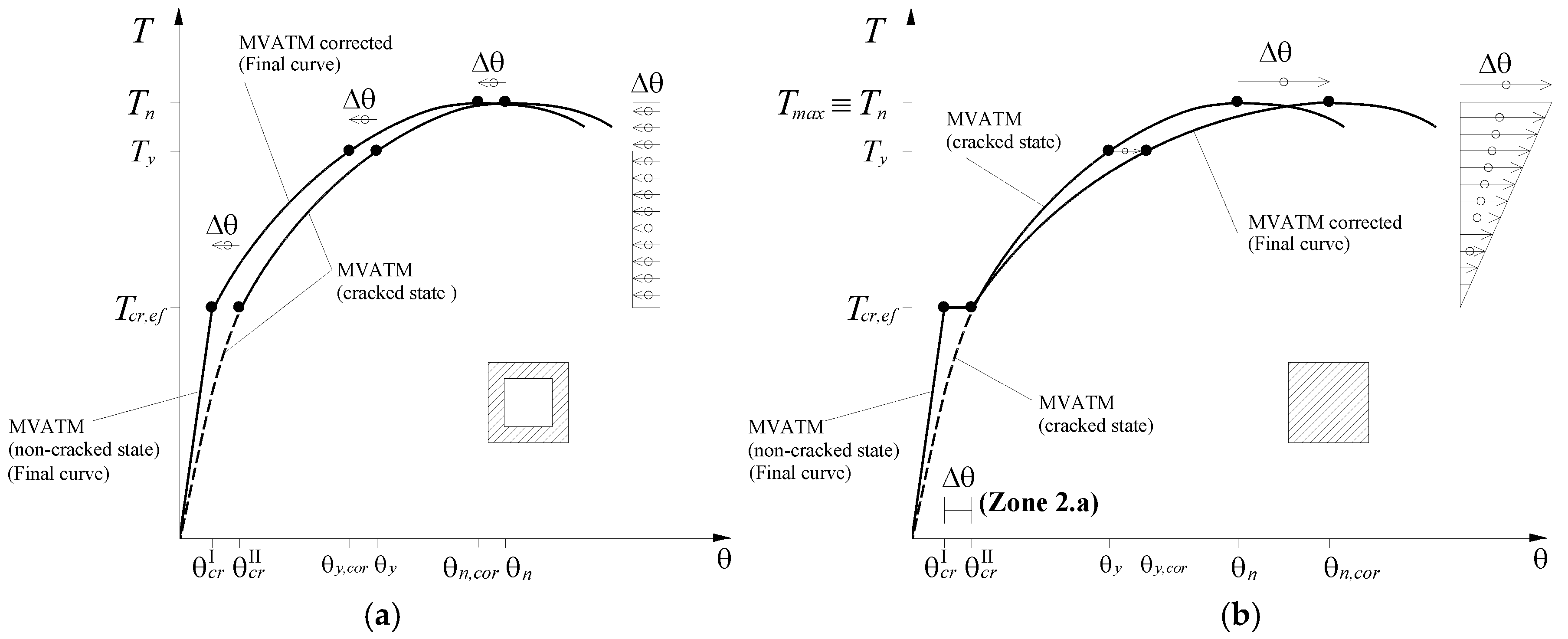
2.3. Zones 2.b and 3 (Cracked and Ultimate States)
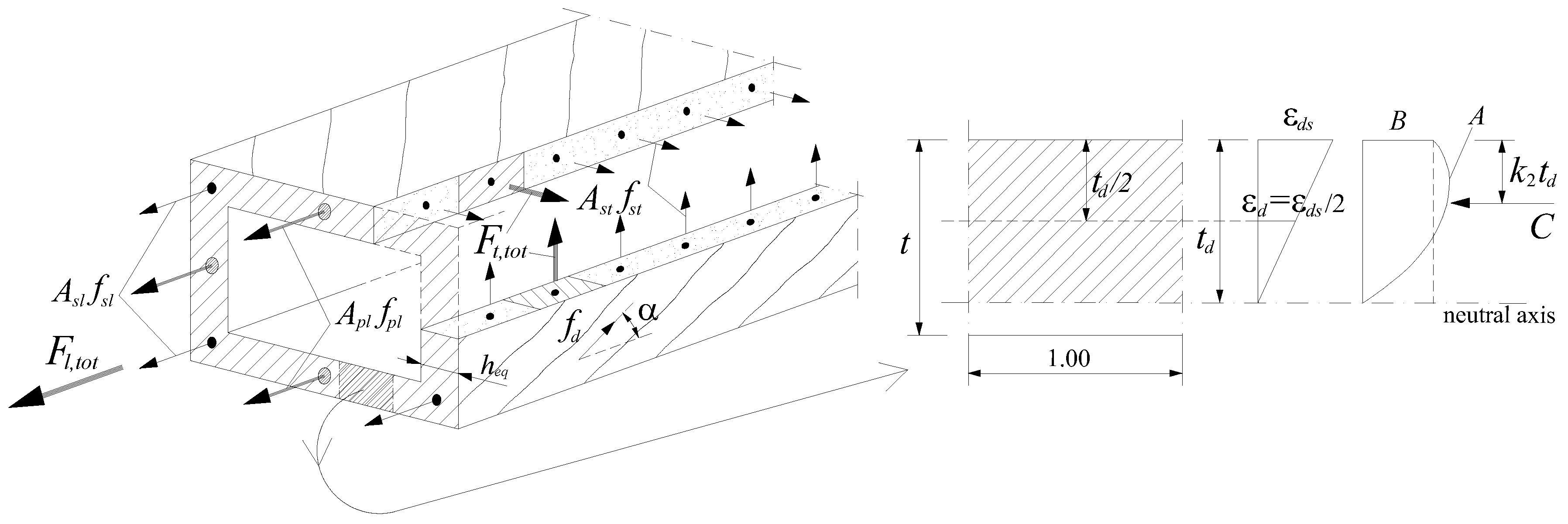
3. Extension of the MVATM for TPC Beams
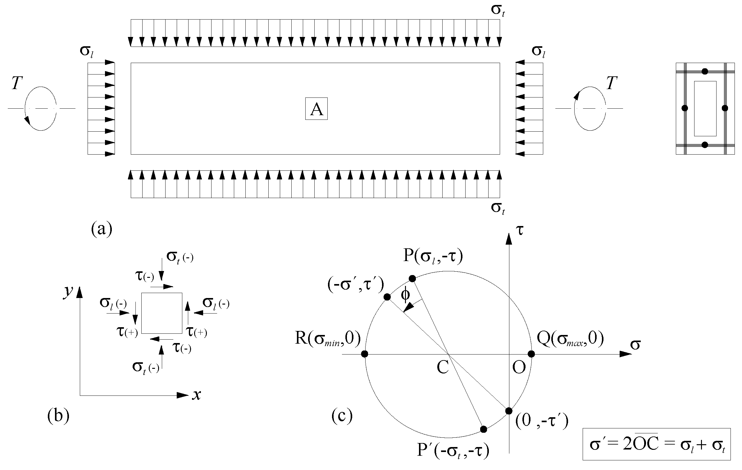
3.1. Non-Cracked State
- ρpt = transversal prestress reinforcement ratio;
- fpt0.1% = conventional proportional stress of the transversal prestress reinforcement.
- -
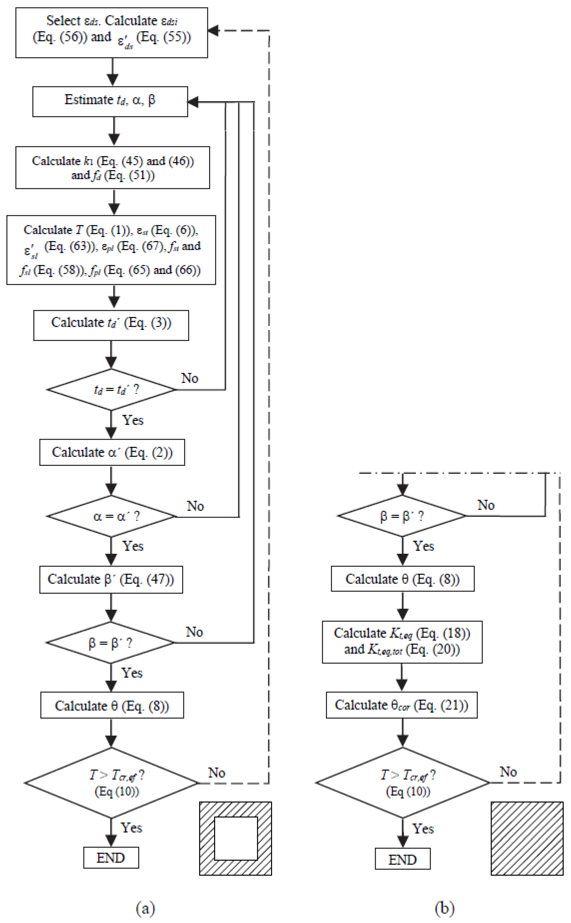
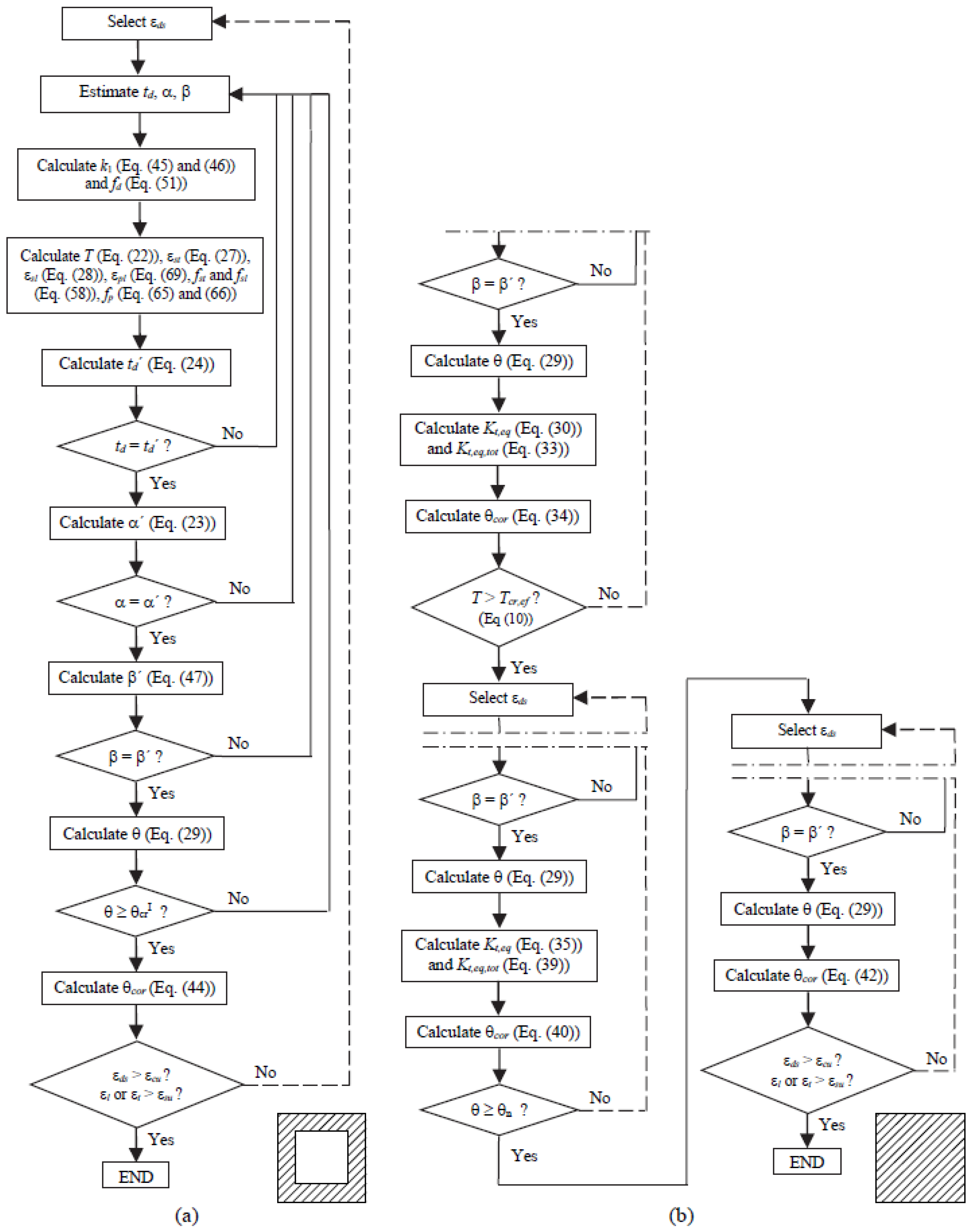
- 1st step: Select εds. Calculate εdsi (Equation (86)) and Equation (55));
- -
- …
- -
- 4th step: Calculate T (Equation (1)), εst (Equation (6)), (Equation (63)), (Equation (83)), εpl (Equation (67), εpt (Equation (81)), fst and fsl (Equations (58)), fpl and fpt (Equations (65) and (66));
- -
- …
- -
- 7th step: Calculate α′ (Equation (78));
- -
- …
- -
- 12th step: T > Tcr,ef ? (Equation (74));
- -
- …
3.2. Zone 2a (Cracked State)
3.3. Zones 2.b and 3 (Cracked and Ultimate States)
4. Theoretical Parametric Study
4.1. Reference Beams and Study Variables
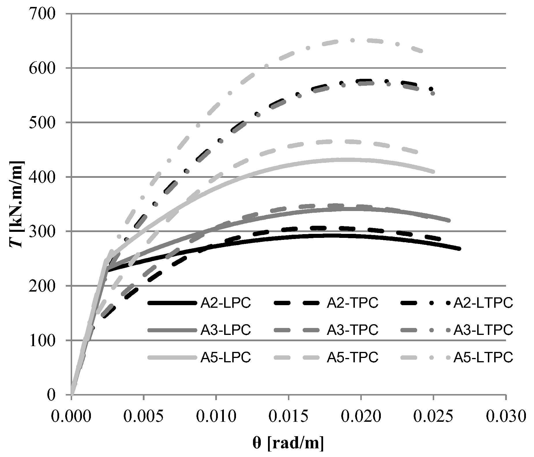
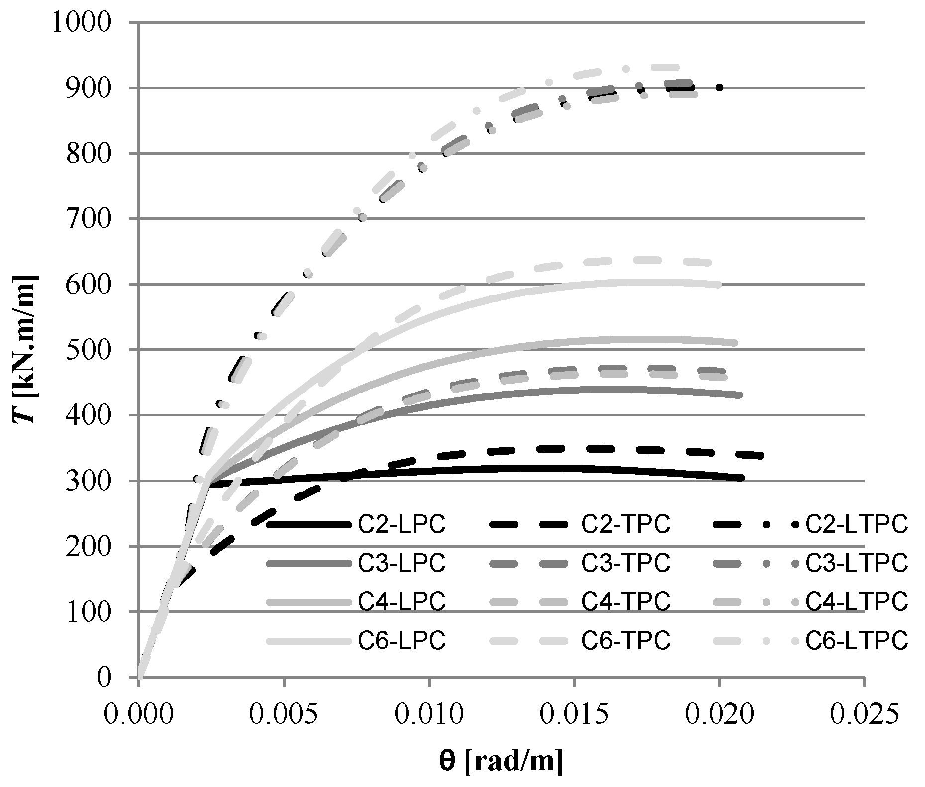
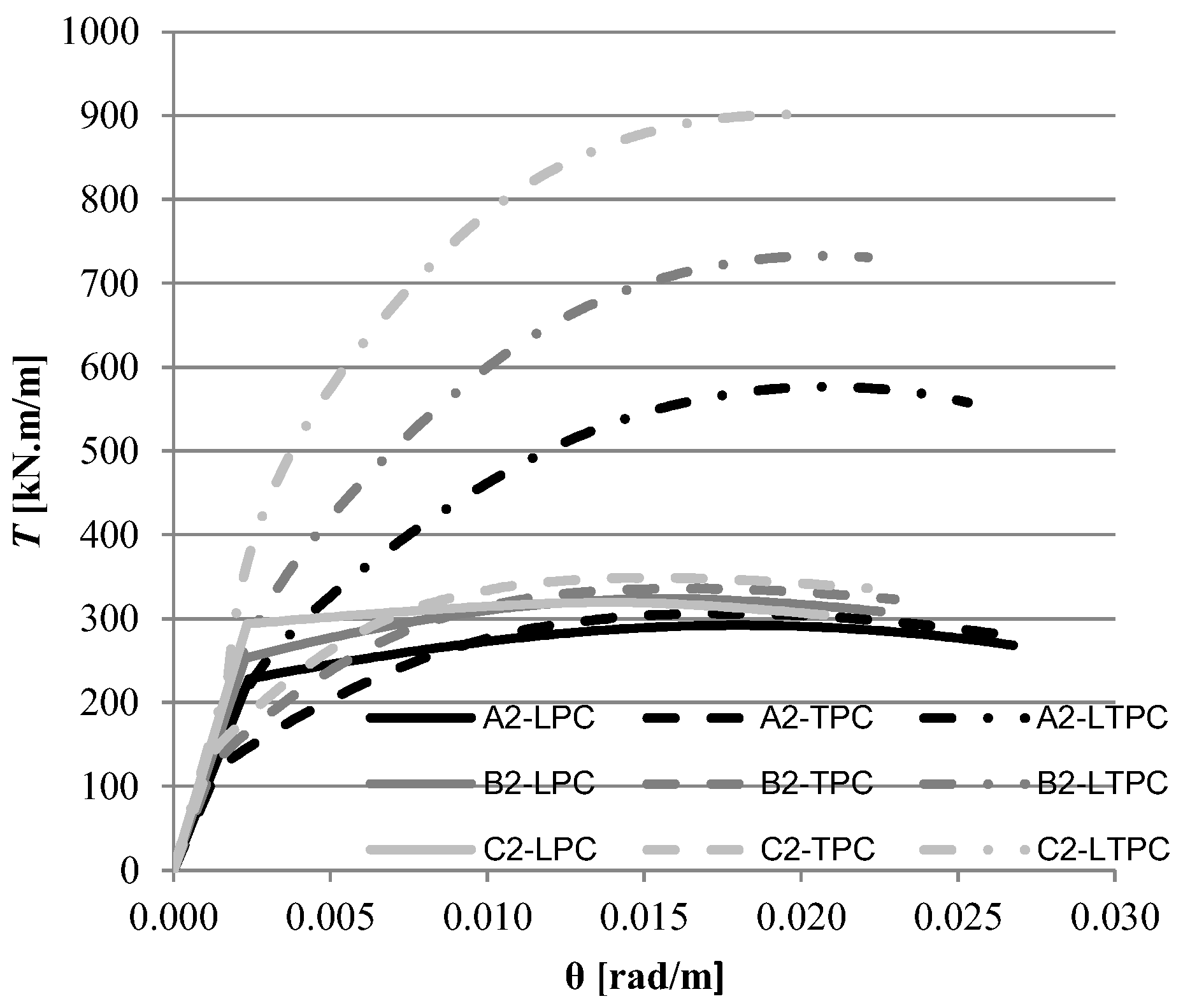
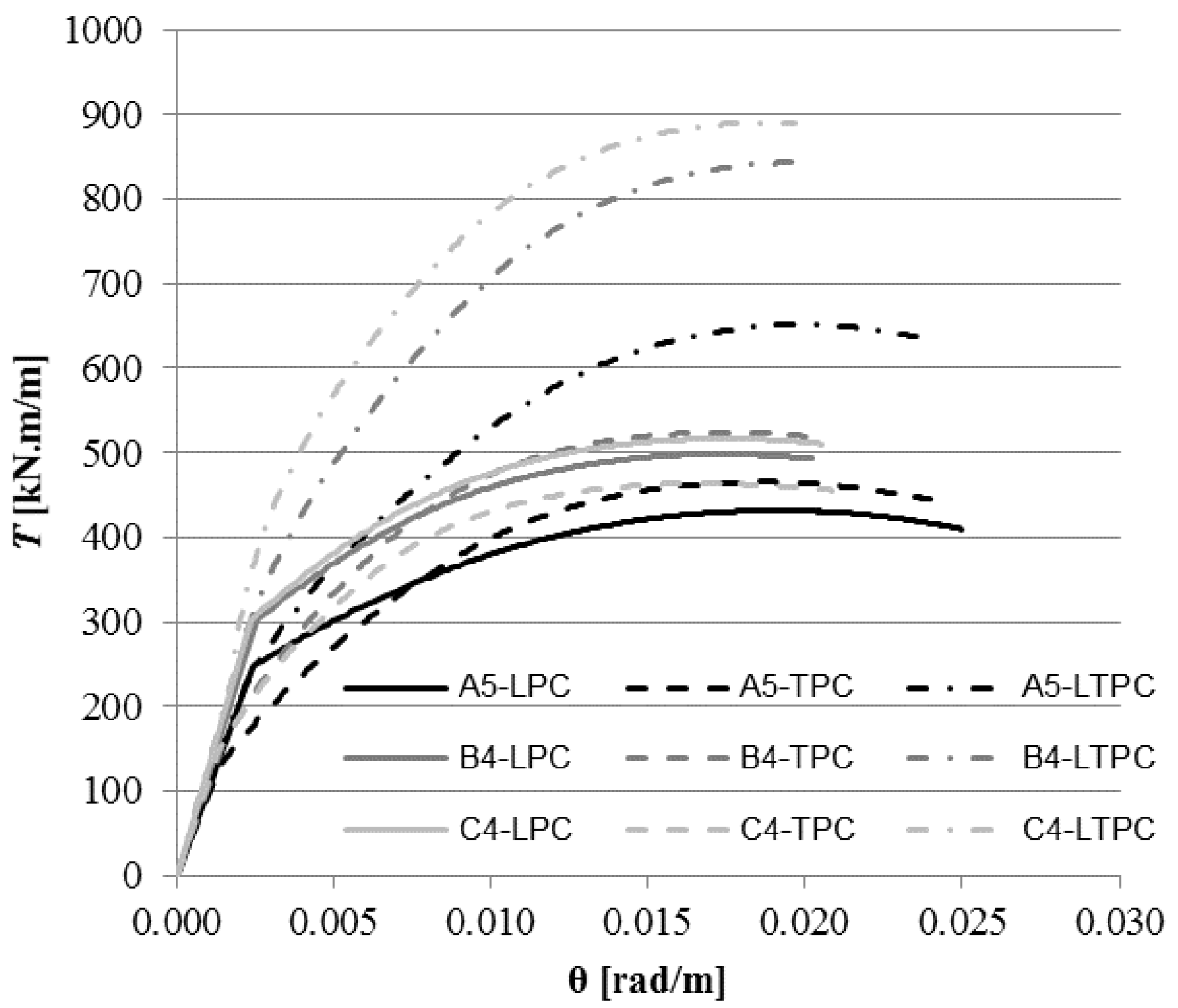
4.2. Comparative Analysis
5. Conclusions
Author Contributions
Conflicts of Interest
References
- Rausch, E. Berechnung des Eisenbetons gegen Verdrehung (Design of Reinforced Concrete in Torsion). Ph.D. Thesis, Technische Hochschule, Berlin, German, 1929. [Google Scholar]
- Andersen, P. Experiments with Concrete in Torsion. Trans. ASCE 1935, 100, 949–983. [Google Scholar]
- Cowan, H.J. Elastic Theory for Torsional Strength of Rectangular Reinforced Concrete Beams. Mag. Concr. Res. 1950, 2, 3–8. [Google Scholar] [CrossRef]
- Lampert, P.; Thurlimann, B. Torsionsversuche an Stahlbetonbalken (Torsion Tests of Reinforced Concrete Beams) Bericht, Nr. 6506-2. Inst. Fur Baustatik ETH Zurich. 1969, 101. (In Germany) [Google Scholar]
- Elfgren, L. Reinforced Concrete Beams Loaded in Combined Torsion, Bending and Shear; Division of Concrete Structures, Chalmers University of Technology: Goteborg, Sweden, 1972. [Google Scholar]
- Collins, M.P.; Mitchell, D. Shear and Torsion Design of Prestressed and Non-Prestressed Concrete Beams. J. Prestress. Concr. Inst. 1980, 25, 32–100. [Google Scholar] [CrossRef]
- Hsu, T.T.C.; Mo, Y.L. Softening of Concrete in Torsional Members—Theory and Tests. J. Am. Concr. Inst. 1985, 82, 290–303. [Google Scholar]
- Hsu, T.T.C.; Mo, Y.L. Softening of Concrete in Torsional Members—Prestressed Concrete. J. Am. Concr. Inst. 1985, 82, 603–615. [Google Scholar]
- Rahal, K.N.; Collins, M.P. Simple Model for Predicting Torsional Strength of Reinforced and Prestressed Concrete Sections. J. Am. Concr. Inst. 1996, 93, 658–666. [Google Scholar]
- Bhatti, M.A.; Almughrabi, A. Refined Model to Estimate Torsional Strength of Reinforced Concrete Beams. J. Am. Concr. Inst. 1996, 93, 614–622. [Google Scholar]
- Wang, W.; Hsu, T.T.C. Limit Analysis of Reinforced Concrete Beams Subjected to Pure Torsion. J. Struct. Eng. 1997, 123, 86–94. [Google Scholar] [CrossRef]
- Jeng, C.H.; Hsu, T.T.C. A Softened Membrane Model for Torsion in Reinforced Concrete Members. Eng. Struct. 2009, 31, 1944–1954. [Google Scholar] [CrossRef]
- Jeng, C.H.; Chiu, H.J.; Chen, C.S. Modelling the Initial Stresses in Prestressed Concrete Members under Torsion. In Structures Congress; ASCE: Orlando, FL, USA, 2010; pp. 1773–1781. [Google Scholar]
- Jeng, C.H. Unified Softened Membrane Model for Torsion in Hollow and Solid Reinforced Concrete Members: Modeling Precracking and Postcracking Behavior. J. Struct. Eng. 2015, 141, 04014243. [Google Scholar] [CrossRef]
- Hsu, T.T.C.; Zhu, R.R.H. Softened Membrane Model for Reinforced Concrete Elements in Shear. Struct. J. Am. Concr. Inst. 2002, 99, 460–469. [Google Scholar]
- Bernardo, L.F.A.; Andrade, J.M.A.; Lopes, S.M.R. Modified variable angle truss-model for torsion in reinforced concrete beams. Mater. Struct. 2012, 45, 1877–1902. [Google Scholar] [CrossRef]
- Bernardo, L.F.A.; Andrade, J.M.A.; Nunes, N.C.G. Generalized softened variable angle truss-model for reinforcement concrete beams under torsion. Mater. Struct. 2015, 48, 2169–2193. [Google Scholar] [CrossRef]
- Andrade, J.M.A. Modelling of the Global Behavior of Beams under Torsion—Generalization of the Space Truss Analogy with Variable Angle. Ph.D. Thesis, Department of Civil Engineering and Architecture, Faculty of Engineering of University of Beira Interior, Covilhã, Portugal, 2010. (In Portuguese). [Google Scholar]
- Taborda, C.S.B. Generalization of the VATM and GSVATM to Model Structural Concrete Beams under Torsion Combined with Uniforme Axial Stress State. Ph.D. Thesis, Department of Civil Engineering and Architecture, Faculty of Engineering of University of Beira Interior, Covilhã, Portugal, 2017. (In Portuguese). [Google Scholar]
- Bernardo, L.F.A.; Teixeira, M.M. Modified Softened Truss-Model for PC Beams under Torsion. J. Build. Eng. 2018. in review. [Google Scholar]
- Laffranchi, M. Zur Konzeption Gekrümmter Brücken; IBK Report; Institut für Baustatik und Konstruktion: Zürich, Switzerland, 1999. (In Germany) [Google Scholar]
- ACI Committee 318. Building Code Requirements for Reinforced Concrete, (ACI 318-14); American Concrete Institute: Farmington Hills, MI, USA, 2014. [Google Scholar]
- Belarbi, A.; Hsu, T.T.C. Constitutive Laws of Softened Concrete in Biaxial Tension-Compression; Research Report UHCEE 91-2; University of Houston: Houston, TX, USA, 1991. [Google Scholar]
- Zhang, L.X.; Hsu, T.T.C. Behavior and Analysis of 100 MPa Concrete Membrane Elements. J. Struct. Eng. 1998, 124, 24–34. [Google Scholar] [CrossRef]
- Belarbi, A.; Hsu, T.T.C. Constitutive Laws of Softened Concrete in Biaxial Tension-Compression. Struct. J. Am. Concr. Inst. 1995, 92, 562–573. [Google Scholar]
- Bernardo, L.F.A.; Lopes, S.M.R. Torsion in HSC Hollow Beams: Strength and Ductility Analysis. ACI Struct. J. 2009, 106, 39–48. [Google Scholar]
- Bernardo, L.F.A.; Lopes, S.M.R. Theoretical Behavior of HSC Sections under Torsion. Eng. Struct. 2011, 33, 3702–3714. [Google Scholar] [CrossRef]
- Bernardo, L.F.A.; Lopes, S.M.R. Behavior of Concrete Beams under Torsion—NSC Plain and Hollow Beams. Mater. Struct. 2008, 41, 1143–1167. [Google Scholar] [CrossRef]
- Hsu, T.T.C. Torsion of Reinforced Concrete; Van Nostrand Reinhold Company: New York, NY, USA, 1984. [Google Scholar]


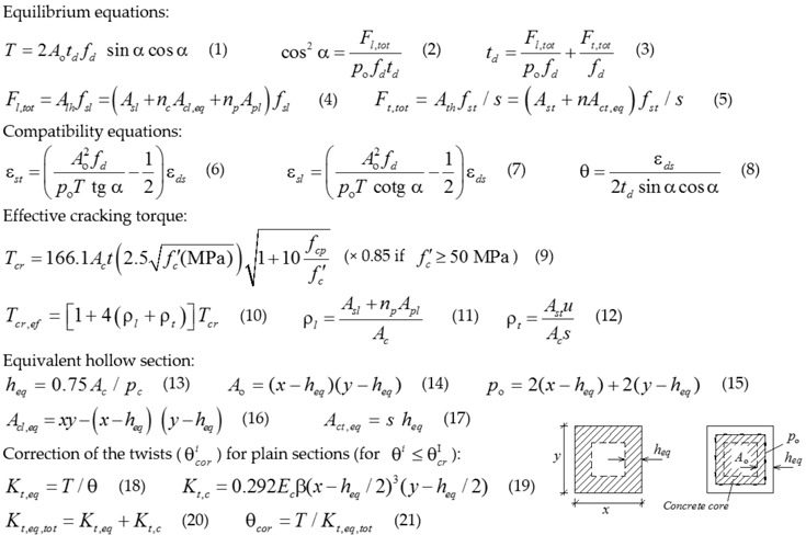 |
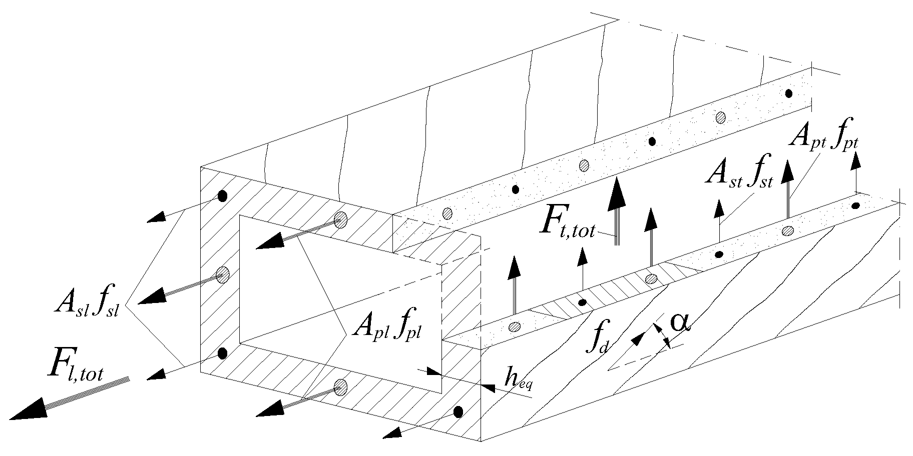
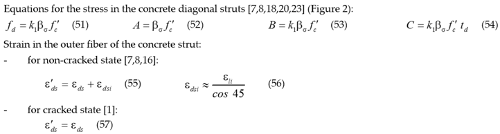
| where: = concrete compressive strength (uniaxial); Ao = area limited by the center line of the flow of shear stresses; Ac = area limited by the outer perimeter of the section (includes hollow area): , with x and y the width and height of the cross section; Alh; Ath = homogenized steel areas in the longitudinal and transversal direction, respectively; Acl,eq; Act,eq = equivalent area of effective concrete in tension for the longitudinal and transversal direction, pc = perimeter of area Ac; po = perimeter of area Ao; t = thickness of the wall; u = perimeter of the centerlines of the closed stirrups: , with x1 and y1 the width and height of the centerlines of legs of the closed stirrups; s = spacing of the transversal reinforcement; fd = stress in the diagonal concrete strut; Asl; Apl = total area of the longitudinal ordinary and prestress reinforcement, respectively; Ast = area of one unit of the transversal reinforcement; εds = maximum compressive strain in the outer fiber in the strut direction; fsl; fpl = stress in the longitudinal ordinary and prestress reinforcement, respectively; fst = stress in the transversal reinforcement; fcp = stress in the concrete due to prestress; nc = Ec/Es, with Ec and Es the Young’s Modulus for concrete and ordinary reinforcement, respectively; np = Ep/Es, with Ep and Es the Young’s Modulus for prestress and ordinary reinforcement, respectively; ρl; ρt = longitudinal and transversal reinforcement ratio, respectively (see Section 3.1); Kt,eq = equivalent secant torsional stiffness; Kt,eq,tot = equivalent total torsional stiffness of the full section (including concrete core); Kt,c = torsional stiffness of the concrete core; β = St. Venant’s coefficient. |
 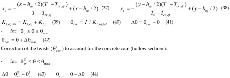 |
| where: xc; yc = width and height of the cross section core, respectively; Δθmax = correction of the twists. |
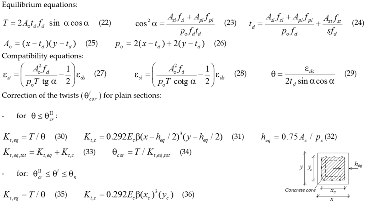
 |
 |
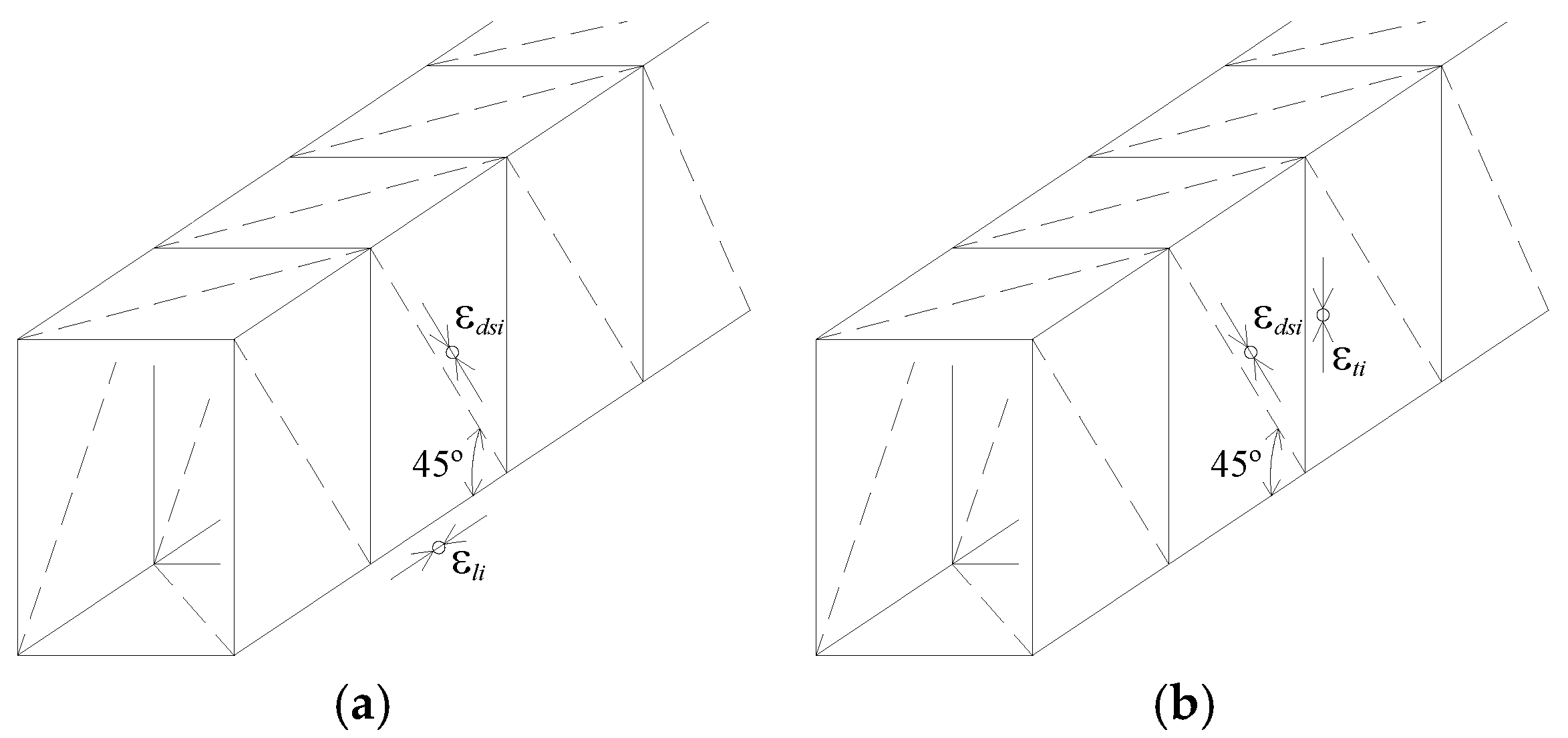
| where: εo = strain corresponding to ; εc1 = tensile strain in the perpendicular direction to the strut; εdsi = initial compressive strain in the outer fiber of the concrete strut due to prestress; = effective compressive strain in the outer fiber of the concrete strut; ρl; ρt = longitudinal and transversal reinforcement ratio, respectively (see Section 3.1); ρp = longitudinal prestress reinforcement ratio (see Section 3.1); fsly; fsty = yielding stress in the longitudinal and transversal reinforcement, respectively; fpl0.1% = conventional proportional stress of the longitudinal prestress reinforcement. |
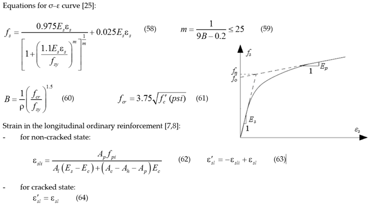 |
| where: Es; Ec = Young’s modulus of the ordinary reinforcement and concrete, respectively; Ac = area limited by the external perimeter of the section; Ah = hollow area of the section (for plain sections: Ah = 0); fcr = concrete cracking stress; ρ = reinforcement ratio (see Section 3.1); εsli = initial compressive strain in the longitudinal ordinary reinforcement; = effective strain in the longitudinal ordinary reinforcement; fsy = reinforcement yielding stress. |
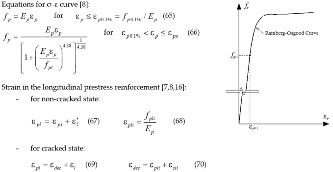 |
| where: Ep = Young’s modulus of the prestress reinforcement; fpi = initial stress due to prestress in the prestress reinforcement; fpt = ultimate stress of the prestress reinforcement; fp0.1% = conventional proportional stress of the longitudinal prestress reinforcement; εpl = strain in the prestress reinforcement; εdec = strain in the prestress reinforcement at concrete’s decompression; εpli = initial tensile strain in the prestress reinforcement; εsli = initial compressive strain in the longitudinal ordinary reinforcement; = effective strain in the longitudinal ordinary reinforcement; εp0.1% = strain corresponding to fp0.1%. |
| Beam | x; y cm | T cm | x1 cm | y1 cm | Asl cm2 | Ast/s cm2/m | ρsl % | ρst % | fcm MPa | fctm MPa | flym MPa | ftym MPa | Ec GPa | % | εcu % |
|---|---|---|---|---|---|---|---|---|---|---|---|---|---|---|---|
| A2 | 60 | 10.7 | 53.8 | 53.1 | 14.0 | 6.3 | 0.39 | 0.37 | 47.3 | 3.5 | 672 | 696 | 36.1 | 0.20 | 0.35 |
| A3 | 60 | 10.9 | 54.0 | 53.5 | 18.1 | 8.3 | 0.50 | 0.49 | 46.2 | 3.4 | 672 | 715 | 35.8 | 0.20 | 0.35 |
| A5 | 60 | 10.4 | 52.8 | 52.8 | 30.7 | 14.1 | 0.85 | 0.83 | 53.1 | 3.8 | 724 | 672 | 37.5 | 0.20 | 0.35 |
| B2 | 60 | 10.8 | 53.3 | 53.4 | 14.6 | 6.7 | 0.41 | 0.40 | 69.8 | 4.1 | 672 | 696 | 39.4 | 0.21 | 0.33 |
| B4 | 60 | 11.2 | 52.3 | 53.6 | 32.2 | 15.1 | 0.89 | 0.89 | 79.8 | 4.4 | 724 | 672 | 41.0 | 0.21 | 0.31 |
| C2 | 60 | 10.0 | 53.2 | 53.3 | 14.0 | 6.3 | 0.39 | 0.37 | 94.8 | 4.9 | 672 | 696 | 43.2 | 0.22 | 0.28 |
| C3 | 60 | 10.3 | 54.5 | 54.0 | 23.8 | 10.5 | 0.66 | 0.63 | 91.6 | 4.8 | 724 | 715 | 42.8 | 0.22 | 0.28 |
| C4 | 60 | 10.3 | 54.6 | 54.5 | 30.7 | 14.1 | 0.85 | 0.86 | 91.4 | 4.8 | 724 | 672 | 42.7 | 0.22 | 0.28 |
| C6 | 60 | 10.4 | 53.3 | 52.9 | 48.3 | 22.6 | 1.34 | 1.34 | 87.5 | 4.7 | 724 | 724 | 42.2 | 0.22 | 0.29 |
| Type | LPC | TPC | LTPC | |||||||||||||
|---|---|---|---|---|---|---|---|---|---|---|---|---|---|---|---|---|
| Beam | Apl cm2 | ρpl % | fpli MPa | fcpl MPa | Apt/sp cm2/m | ρpt % | fpti MPa | fcpt MPa | Apl cm2 | Apt/sp cm2/m | ρpl % | ρpt % | fpli MPa | fcpl MPa | fpti MPa | fcpt MPa |
| A2 | 16.63 | 0.46 | 1350 | 10.64 | 8.44 | 0.46 | 1350 | 10.64 | 8.32 | 4.22 | 0.23 | 0.23 | 1350 | 5.32 | 1350 | 5.32 |
| A3 | 16.48 | 0.46 | 1350 | 10.40 | 8.39 | 0.46 | 1350 | 10.40 | 8.24 | 4.20 | 0.23 | 0.23 | 1350 | 5.20 | 1350 | 5.20 |
| A5 | 18.26 | 0.51 | 1350 | 11.95 | 9.20 | 0.51 | 1350 | 11.95 | 9.13 | 4.60 | 0.25 | 0.25 | 1350 | 5.97 | 1350 | 5.97 |
| B2 | 24.73 | 0.69 | 1350 | 15.71 | 12.56 | 0.69 | 1350 | 15.71 | 12.36 | 6.28 | 0.34 | 0.34 | 1350 | 7.85 | 1350 | 7.85 |
| B4 | 29.08 | 0.81 | 1350 | 17.96 | 14.90 | 0.81 | 1350 | 17.96 | 14.54 | 7.45 | 0.40 | 0.40 | 1350 | 8.98 | 1350 | 8.98 |
| C2 | 31.60 | 0.88 | 1350 | 21.33 | 15.80 | 0.88 | 1350 | 21.33 | 15.80 | 7.90 | 0.44 | 0.44 | 1350 | 10.67 | 1350 | 10.67 |
| C3 | 31.26 | 0.87 | 1350 | 20.61 | 15.72 | 0.87 | 1350 | 20.61 | 15.63 | 7.86 | 0.43 | 0.43 | 1350 | 10.31 | 1350 | 10.31 |
| C4 | 31.19 | 0.87 | 1350 | 20.57 | 15.69 | 0.87 | 1350 | 20.57 | 15.60 | 7.85 | 0.43 | 0.43 | 1350 | 10.28 | 1350 | 10.28 |
| C6 | 30.09 | 0.84 | 1350 | 19.69 | 15.17 | 0.84 | 1350 | 19.69 | 15.05 | 7.58 | 0.42 | 0.42 | 1350 | 9.84 | 1350 | 9.84 |
© 2018 by the authors. Licensee MDPI, Basel, Switzerland. This article is an open access article distributed under the terms and conditions of the Creative Commons Attribution (CC BY) license (http://creativecommons.org/licenses/by/4.0/).
Share and Cite
Bernardo, L.; Andrade, J.; Teixeira, M. Parametric Study of the Behavior of Longitudinally and Transversally Prestressed Concrete under Pure Torsion. Designs 2018, 2, 12. https://doi.org/10.3390/designs2020012
Bernardo L, Andrade J, Teixeira M. Parametric Study of the Behavior of Longitudinally and Transversally Prestressed Concrete under Pure Torsion. Designs. 2018; 2(2):12. https://doi.org/10.3390/designs2020012
Chicago/Turabian StyleBernardo, Luís, Jorge Andrade, and Mafalda Teixeira. 2018. "Parametric Study of the Behavior of Longitudinally and Transversally Prestressed Concrete under Pure Torsion" Designs 2, no. 2: 12. https://doi.org/10.3390/designs2020012