Abstract
In this paper, we investigate the design and performance of static feedback controllers with partial-state information for the seismic protection of tall buildings equipped with incomplete multi-actuation systems. The proposed approach considers a partially instrumented multi-story building with an incomplete system of interstory force–actuation devices implemented on selected levels of the building, and an associated set of collocated sensors that measure the corresponding interstory drifts and interstory velocities. The main elements of the proposed controller design methodology are presented by means of a twenty-story building equipped with a system of ten interstory actuators arranged in three different layouts: concentrated, semi-distributed and fully-distributed. For these control configurations, partial-state controllers are designed following a static output-feedback H-infinity controller design approach, and the corresponding frequency and time responses are investigated. The obtained results clearly indicate that the proposed partial-state controllers are effective in mitigating the building seismic response. They also show that a suitable distribution of the instrumented stories is a relevant factor in the control system performance.
1. Introduction
Vibration control of large buildings and civil structures is an important issue that has attracted increasing research attention over the last years [1,2,3,4,5]. In recent works, a variety of complex and sophisticated control systems with multiple actuation devices has been considered to provide an improved level of vibrational protection. Thus, for example, the usage of multiple Tuned Mass Dampers (TMDs) is proposed in [6,7,8], an innovative Multiple Tuned Mass Damper system that uses the building floors as TMD devices is investigated in [9,10], the combined action of TMDs and Tuned Liquid Column Dampers for control of wind-induced vibrations in super tall buildings is discussed in [11], a system of Multiple Active Tendons is proposed in [12] for vibration control of irregular buildings, and a system of Multiple Cardan Gyroscopes for vibration control of tower structures is proposed in [13]. Interstory force–actuation devices, as those schematically displayed in Figure 1b and Figure 2, are particularly suitable to make up multi-actuator systems for large-scale structures. This kind of actuation device facilitates acquiring valuable state information by means of collocated sensors [14], and also allows for considering complex control configurations formed by a large set of actuators and sensors that are distributed throughout the structure. Relevant works in this line include the design and study of complex multi-actuation systems with information constraints using advanced control design methodologies. Thus, the design of optimal passive-damping systems using a state-feedback control approach is conducted in [15,16]. In [17], decentralized time-delayed dynamic output-feedback controllers are obtained using a homotopic transformation. Decentralized and semi-decentralized control strategies based on substructure decomposition are investigated in [18,19,20]. Decentralized static output-feedback controllers are obtained in [21] by solving a single-step Linear Matrix Inequality (LMI) optimization problem. Static output-feedback controllers with a finite frequency range are proposed in [22] and further developed in [23]. An adaptive control strategy for nonlinear building models with semi-active magnetorheological dampers is investigated in [24]. Dynamic output-feedback controllers with both continuous and sampled feedback information are computed in [25] by means of iterative LMI procedures. In addition, an LMI formulation for robust non-fragile static controllers with sampled-data feedback information is obtained in [26] using a dissipativity approach.
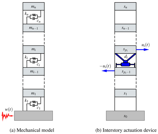
Figure 1.
(a) simplified mechanical model for an n-story building with story masses , stiffness coefficients and damping coefficients , ; and (b) interstory actuation device. The actuation device is implemented at the building position between the stories and . The interstory actuator produces a pair of opposite structural forces of magnitude on the supporting stories and .
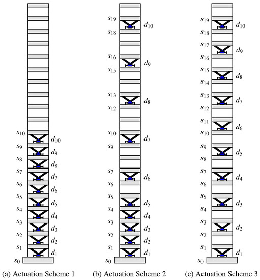
Figure 2.
Incomplete actuation schemes in a 20-story building. (a) concentrated actuation scheme AS1 with actuators located at positions ; (b) semi-distributed actuation scheme AS2 with actuators located at positions ; (c) distributed actuation scheme AS3 with actuators located at positions .
In this paper, we present a controller design methodology for the seismic protection of tall buildings equipped with a distributed set of actuators and collocated sensors. More specifically, we assume that some of the building stories are equipped with an interstory force–actuation device and a sensing unit that can measure the corresponding interstory drift and interstory velocity [14]. We also assume that the building is only partially instrumented and, consequently, the available state information is incomplete. This kind of control configuration is poorly studied in the literature and poses serious computational challenges in large-dimensional problems. The solution proposed in this work is based on an advanced static output-feedback approach that allows for obtaining controllers with incomplete state information by solving a two-step Linear Matrix Inequality (LMI) optimization problem [27,28,29]. This controller design methodology is applied to study the effectiveness of different configurations of incomplete multi-actuator systems with partial state information, paying special attention to the influence of the actuation system distribution on the control performance. In particular, we consider three different actuation schemes for a 20-story building equipped with a system of 10 actuation devices: a concentrated actuation scheme, a semi-distributed actuation scheme, and a fully-distributed actuation scheme (see Figure 2). For these three actuation layouts, partial-state controllers that only use the state information corresponding to the instrumented stories are designed and their frequency and time responses are investigated. The obtained results confirm the effectiveness of structural vibration control strategies with incomplete multi-actuator systems and partial state information. They also point out that an enhanced performance can be achieved by a suitable distribution of the instrumented stories.
The rest of the paper is organized as follows: in Section 2, a state-space model for the twenty-story building with incomplete actuation schemes is presented. In Section 3, full-state and partial-state controllers are designed for the different control configurations and the corresponding frequency characteristics are investigated. In Section 4, numerical simulations of the time responses are conducted and illustrative peak-value plots of the interstory drifts, absolute story accelerations and control efforts are presented and compared. Finally, in Section 5, some conclusions and future research directions are briefly discussed.
2. Building Model
In this section, we provide a dynamical model for the lateral displacement of an n-story building equipped with different actuation schemes. The particular models corresponding to a twenty-story building with the actuation schemes displayed in Figure 2 are discussed in detail. These particular models will be used in the controllers designs presented in Section 3 and the numerical simulations carried out in Section 4. The building motion can be described by the second-order differential equation
where is the vector of story displacements with respect to the ground, is the seismic ground acceleration and is the vector of control actions. M, and are the mass, damping and stiffness matrices, respectively, which model the mechanical characteristics of the building; is the control location matrix, which determines the structural effect of the actuation forces; and is the disturbance input matrix, which models the effect of the ground disturbance. The mass matrix is a diagonal matrix and the stiffness matrix has the following tridiagonal structure:
where and , denote the mass and stiffness coefficient of the i-th story, respectively (see Figure 1a). When the story damping coefficients , are known, a damping matrix with the structure shown in Equation (2) can be obtained by substituting the coefficients by the corresponding . However, most frequently, the story damping coefficients are unknown. In this case, the damping matrix can be computed from M and K by setting a proper damping ratio on the building modes [30]. The disturbance input matrix has the form , where denotes a vector of dimension n with all its entries equal to 1. The structure of the control location matrix depends on the particular characteristics of the considered actuation scheme. In this work, we assume that the control forces are exerted by a system of m devices , where is an interstory actuator implemented at the building position . As indicated in Figure 1b, the actuation device produces a force on the story number (upper story), and an opposite force on the story number (lower story). An actuation scheme is determined by a list of actuation positions . If the actuation scheme is complete, that is, if an actuation device is implemented at every building level, then the list of actuation positions is and the corresponding control location matrix is a square matrix of size n with the following upper-diagonal band form:
For an incomplete actuation scheme with a list of positions , , the corresponding control location matrix is a rectangular matrix of size that can be obtained by extracting the corresponding columns from , that is:
Thus, for the concentrated actuation scheme AS1 in Figure 2a, the list of positions is and we have the control location matrix that is:
For the semi-distributed actuation scheme AS2 in Figure 2b, the actuation positions are and the corresponding control location matrix has the following form:
Finally, for the fully-distributed actuation scheme AS3 in Figure 2c, the list of actuation positions is and we obtain the control location matrix
The interstory drift is the relative displacement between the consecutive stories located at the building levels i and . The vector of interstory drifts can be computed as follows:
By considering the state vector
that arranges the interstory drifts and interstory velocities in increasing order, we obtain a first-order state-space model
with
where is the identity matrix of dimension n, represents a zero-matrix of the indicated dimensions, and is the change-of-basis matrix corresponding to the state transformation
3. Controllers Design
In this section, we consider a twenty-story building model defined by the mass, stiffness and damping parameters collected in Table 1 [14], and equipped with the incomplete actuation schemes AS1, AS2 and AS3 displayed in Figure 2. For these three actuation layouts, we first compute optimal state-feedback controllers by assuming that the building incorporates a complete system of sensors that provide full-access to the state information. Next, we consider a more realistic scenario of a partially instrumented building equipped with a restricted system of sensors, which are collocated with the actuation devices. For this second control setup, we compute suboptimal controllers following a static output-feedback approach.

Table 1.
Twenty-story building model: mass, stiffness and damping characteristics.
3.1. Controllers with Full-State Information
Assuming that the control objective is to reduce the building vibrational response by means of moderate control actions, we consider the vector of controlled-outputs
defined by the matrices
where is a scaling factor that allows adjusting the control action intensity. When the full state information is available, we can consider a state-feedback controller
defined by the state gain matrix , which produces the closed-loop system
with
The controller design methodology considers the system norm
where is the usual continuous 2-norm. The value represents the worst-case gain from the disturbance-input to the closed-loop controlled-output defined by the control gain matrix G. The controller design objective is to obtain an optimal state-feedback controller that produces an asymptotically stable matrix and attains a minimum -norm value . Using an LMI formulation, the optimal state-feedback controller can be computed by solving the following optimization problem [31]:
where * denotes the transpose of the symmetric entry and , are the optimization variables. If an optimal value is attained in for the pair , then the state-feedback gain matrix is an optimal solution to the controller synthesis problem and the corresponding -value can be computed as .
For a given state-feedback controller , the corresponding -value can also be computed by considering the disturbance to controlled-output closed-loop transfer function
and solving the optimization problem
where , is the frequency in hertz, and denotes the maximum singular value.
To obtain an optimal state-feedback control gain matrix for the actuation scheme AS1, we solve the LMI optimization problem with the values , ; the matrices A, B, E in Equation (11) corresponding to the values in Table 1 and the control location matrix in Equation (5); and the controlled-output matrices , in Equation (15) with the scaling factor =. Proceeding in a similar way, we also compute optimal state-feedback control gain matrices and for the actuation schemes AS2 and AS3 using, respectively, the control location matrices in Equation (6) and in Equation (7). The -values obtained for the full-state optimal controllers are the following:
and the corresponding frequency responses are displayed in Figure 3. Looking at the overall view presented in Figure 3a, it can be appreciated that the three controllers produce a significant reduction of the building resonant peaks. In accordance with the obtained -values, the plots in Figure 3b show that a slightly higher performance is attained by the concentrated actuation scheme AS1 with the controller in the main resonant peak. However, looking again at the overall view in Figure 3a, it should be noted that a better behavior is exhibited by the distributed actuation schemes AS2 and AS3 in the second resonant peak. The -value corresponding to the uncontrolled system is . The relative -value reductions with respect to the uncontrolled building response attained by the optimal full-state controllers are collected in Table 2.
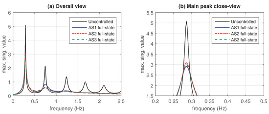
Figure 3.
Frequency response of the optimal controllers with full-state information. Maximum singular values of the closed-loop transfer functions (blue solid line), (red dash-dotted line) and (green dashed line), and the open-loop transfer function (black solid line). (a) overall view of the first five resonant modes; and (b) close view of the main resonant peak.

Table 2.
Percentages of -value reductions attained by the full-state and partial-state controllers for the actuation schemes AS1, AS2 and AS3 with respect to the -norm of the uncontrolled building .
3.2. Controllers with Partial State Information
In this section, we assume that the available feedback information is supplied by a system of sensors that are collocated with the actuation devices, and provide a vector of measured outputs
where and are, respectively, the interstory drift and interstory velocity associated to the actuation device implemented at the building position (between the stories and ). Using a measured-output matrix , the vector can be written in the form . For a complete actuation scheme, is an identity matrix of dimension . For an incomplete actuation scheme defined by a list of positions , the corresponding measured-output matrix can be obtained by selecting the rows in positions , , from the identity matrix , that is:
Thus, for the concentrated actuation scheme AS1, the list of actuation positions is and the corresponding measured-output matrix has the form . For the distributed actuation scheme AS2, the list of actuation positions is and the associated measured-output matrix is the submatrix of the identity matrix formed by the rows in positions 1, 2, 3, 4, 5, 6, 7, 8, 9, 10, 13, 14, 19, 20, 25, 26, 31, 32, 37 and 38. For the distributed actuation scheme AS3, the list of actuation positions is and the associated measured-output matrix is the submatrix of the identity matrix formed by the rows in positions 1, 2, 5, 6, 9, 10, 13, 14, 17, 18, 21, 22, 25, 26, 29, 30, 33, 34, 37 and 38.
Considering the imposed constraints on the feedback information, we are interested in designing a static output-feedback controller
defined by a constant output-feedback gain matrix , which allows computing the vector of control actions from the vector of measured-outputs by means of a simple matrix multiplication. Now, the closed-loop system has the following form:
with
and the associated -norm takes the value
where the closed-loop transfer function has now the form
In this new context, the controller design aims at obtaining an optimal static output-feedback controller that produces an asymptotically stable closed-loop matrix and, at the same time, attains a minimum -norm value . The effective computation of this kind of optimal controllers for large-scale systems is a difficult problem that poses major theoretical and computational challenges. However, according to the results presented in [27,28], a suboptimal static output-feedback controller can be designed by solving the following LMI optimization problem:
where , and are the optimization variables, Q is a matrix whose columns contain a basis of , and the matrix R has the form
where
are the Moore–Penrose pseudoinverses of and Q, respectively, and is the optimal X-matrix obtained in the LMI optimization problem corresponding to the full-state controller design. If an optimal value is attained in for the triplet ,, then the matrix defines a static output-feedback controller with asymptotically stable closed-loop matrix , and the value provides an upper bound of the associated -norm value .
To design a partial-state controller for the proposed twenty-story building model with the concentrated actuation scheme AS1, we consider the measured-output vector
and solve the LMI optimization problem in Equation (32) with the same matrices A, B, E, , used in the design of the state-feedback gain matrix and the matrices Q, R defined by the measured-output matrix and the optimal X-matrix computed in the associated full-state controller design. As a result, we obtain an output-feedback gain matrix with a -value upper bound . The frequency responses of the partial-state controller and the associated full-state controller are displayed in Figure 4b. The plots in the figure show a small (but clearly appreciable) loss of performance of the partial-state controller (blue solid line) with respect to the full-state controller (black dashed line). Using the closed-loop transfer function and solving the optimization problem in Equation (30), we obtain that the actual -value of the partial-state controller is , which represents an increment of with respect to the optimal value .
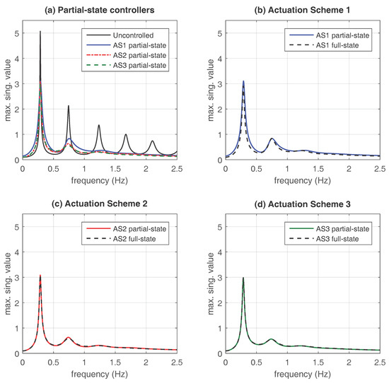
Figure 4.
Frequency response of the full-state and partial-state controllers for the different actuation schemes. (a) overall view of the frequency response corresponding to uncontrolled building (black solid line) and the partial-state controllers defined by the output-feedback control matrices (blue solid line), (red dash-dotted line) and (green dashed line); (b) concentrated actuation scheme AS1. Frequency response of the partial-state controller defined by the output-feedback control matrix (blue solid line) and the full-state controller defined by the state-feedback control matrix (black dashed line); (c) semi-distributed actuation scheme AS2. Frequency response of the partial-state controller defined by the output-feedback control matrix (red solid line) and the full-state controller defined by the state-feedback control matrix (black dashed line); and (d) fully-distributed actuation scheme AS3. Frequency response of the partial-state controller defined by the output-feedback control matrix (green solid line) and the full-state controller defined by the state-feedback control matrix (black dashed line).
For the semi-distributed actuation scheme AS2, the vector of measured outputs contains the interstory drifts and interstory velocities indicated in the list of positions . In this case, we obtain an output-feedback gain matrix with a -value upper bound by solving the LMI optimization problem with the same matrices A, B, E, , used in the design of the state-feedback gain matrix and the matrices Q, R defined by the measured-output matrix and the corresponding auxiliary X-matrix. Comparing the value of the upper bound with the optimal value , it can be seen that the static output-feedback controller is practically optimal. In fact, the plots presented in Figure 4c show that the frequency response of the partial-state controller defined by the output-feedback gain matrix (red solid line) is practically equal to the frequency response of the optimal full-state controller defined by the state-feedback gain matrix (black dashed line).
For the fully-distributed actuation scheme AS3, the vector of measured outputs contains the interstory drifts and interstory velocities indicated in the list of positions . Following the same computational procedure used in the previous cases, we obtain an output-feedback gain matrix with a -value upper bound . By considering the closed-loop transfer function and solving the optimization problem in Equation (30), we find that the actual -value of the partial-state controller is , which matches the optimal value attained by the full-state controller. As it happened with the semi-distributed scheme AS2, looking at the plots presented in Figure 4d, it can be appreciated that the frequency response of the partial-state controller defined by the output-feedback gain matrix (green solid line) is practically equal to the frequency response of the optimal full-state controller defined by the state-feedback gain matrix (black dashed line).
To provide a better comparison of the partial-state controllers behavior, the corresponding frequency responses are displayed together in Figure 4a, where the blue solid line represents the partial-state controller defined by the output-feedback gain matrix , the red dash-dotted line pertains to the partial-state controller defined by , and the green dashed line represents the partial-state controller defined by . The frequency response of the uncontrolled building (black solid line) is also included as a reference. Looking at the plots in this figure, it can be clearly seen that the three partial-state controllers produce a significant reduction of the building resonant peaks. Moreover, considering the percentages of -value reduction collected in Table 2 and the behavior in the secondary resonant peaks, it becomes apparent that the best performance under partial-state information corresponds to the fully-distributed configuration AS3.
Remark 1.
The total number of elements in the control matrix is related to the number of optimization variables in the LMI design problem. This factor can produce a critical increase of the computation time required by the controller design procedure and is a major issue in large-scale problems. For an n-story building with a system of m actuation devices, the full-state control matrices have elements and the proposed partial-state control matrices have elements. Specifically, for the 20-story building with actuation devices considered in this paper, the full-state control matrices have 400 elements and the partial-state control matrices have 200 elements. Obtaining the full-state control matrix by solving the LMI optimization problem in Equation (20) has required a computation time of 42.71 s. Computing the partial-state control matrix by solving the LMI optimization problem in Equation (32) has required an additional computation time of 6.60 s. For the full-state control matrices and , the computation times have been 49.60 s and 43.34 s, respectively, and the additional computation times required to obtain the partial-state controllers and have been 5.28 s and 4.17 s, respectively.
Remark 2.
It should be noted that the R-matrix proposed in Equation (34) uses the optimal X-matrix obtained in the design of the full-state controller. For a given incomplete actuation scheme, the proposed two-step controller design procedure involves computing both the full-state and the partial-state controllers. This approach has the advantage of providing a natural reference for the performance of the suboptimal partial-state controller and can be a computationally effective controller design strategy for large-scale structures with incomplete actuation schemes of moderate dimension.
4. Numerical Results
To illustrate the time-response characteristics of the proposed partial-state controllers, a suitable set of numerical simulations has been carried out using the scaled Kobe 1995 seismic record as ground acceleration input (see Figure 5). For the concentrated actuation scheme AS1, the absolute peak-values of the interstory-drifts, story absolute accelerations and control efforts corresponding to the different control configurations are presented in Figure 6, where the black solid line with squares presents the response of the uncontrolled building, the blue solid line with triangles corresponds to the full-state controller defined by the state-feedback control matrix and the red dashed line with asterisks represents the partial-state controller defined by the output-feedback control matrix . The time responses corresponding to the semi-distributed actuation scheme AS2 and the fully-distributed actuation scheme AS3 are presented in Figure 7 and Figure 8, respectively, using the same colors, line styles and symbols. To complement this graphical information, the percentages of reduction in the interstory drift peak-values with respect to the uncontrolled response at selected levels of the building (see Remark 3) are collected in Table 3, and the maximum control-effort peak-values are presented in Table 4.
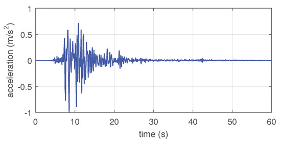
Figure 5.
Ground acceleration disturbance. North-South Kobe 1995 seismic record scaled to an acceleration peak-value of 1 m/s.
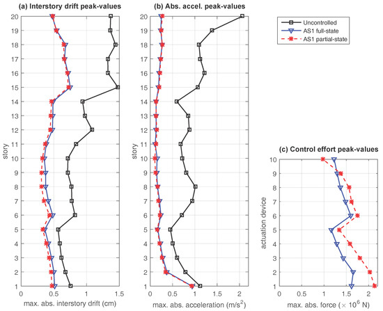
Figure 6.
Time response of the twenty-story building with the concentrated actuation scheme AS1. Seismic response to the scaled North-South Kobe 1995 ground acceleration record for the uncontrolled configuration (black solid line with squares), the full-state controller defined by the state-feedback gain matrix (blue solid line with triangles) and the partial-state controller defined by the output-feedback gain matrix (red dashed line with asterisks). (a) interstory drift peak-values; (b) absolute acceleration peak-values; and (c) control effort peak-values.
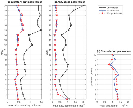
Figure 7.
Time response of the twenty-story building with the semi-distributed actuation scheme AS2. Seismic response to the scaled North-South Kobe 1995 ground acceleration record for the uncontrolled configuration (black solid line with squares), the full-state controller defined by the state-feedback gain matrix (blue solid line with triangles) and the partial-state controller defined by the output-feedback gain matrix (red dashed line with asterisks). (a) interstory drift peak-values; (b) absolute acceleration peak-values; and (c) control effort peak-values.
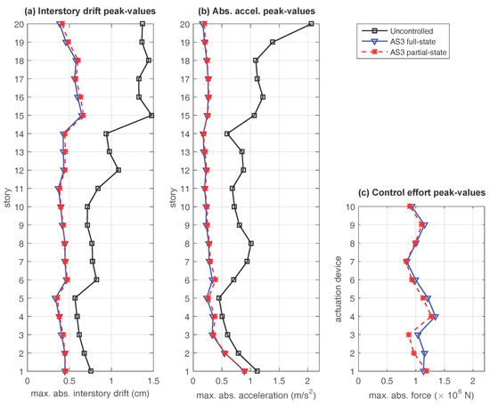
Figure 8.
Time response of the twenty-story building with the fully-distributed actuation scheme AS3. Seismic response to the scaled North-South Kobe 1995 ground acceleration record for the uncontrolled configuration (black solid line with squares), the full-state controller defined by the state-feedback gain matrix (blue solid line with triangles) and the partial-state controller defined by the output-feedback gain matrix (red dashed line with asterisks). (a) interstory drift peak-values; (b) absolute acceleration peak-values; and (c) control effort peak-values.

Table 3.
Percentage of reduction in the interstory drift peak-values with respect to the uncontrolled response for the proposed full-state and partial-state controllers. The North-South Kobe 1995 seismic record, scaled to an acceleration peak of 1 m/s, has been taken as disturbance input.

Table 4.
Maximum control-effort peak values (in MN) corresponding to the computed full-state and partial-state controllers. The North-South Kobe 1995 seismic record, scaled to an acceleration peak of 1 m/s, has been taken as disturbance input.
Looking at the plots in Figure 6, Figure 7 and Figure 8, the following facts can be appreciated: (i) all the proposed controllers provide a good level of reduction in the interstory drift and absolute acceleration peak-values with respect to the uncontrolled response; (ii) for the distributed actuation schemes AS2 and AS3, the behavior of the full-state controller and the partial-state controller are very similar; and (iii) for the concentrated actuation scheme AS1, the interstory drift peak-values produced by the partial-state controller are slightly smaller than those attained by the full-state controller. However, significantly larger control-effort peak-values are also required by the partial-state controller. These time-response results are entirely consistent with the frequency-response characteristics observed in Section 3, and indicate that the performance of the partial-state controllers is not affected by the reduced feedback information in the distributed actuation schemes AS2 and AS3. In contrast, a noticeable loss of performance can be observed in the partial-state controller corresponding to the concentrated actuation scheme AS1. The same facts can be appreciated by looking at the data collected in Table 3 and Table 4, where it becomes apparent that larger percentages of reduction in the interstory drift peak-values are attained by the distributed actuations schemes AS2 and AS3 with smaller control-effort peaks. Particularly remarkable is the performance of the fully-distributed partial-state controller , which produces larger reductions in the interstory drift peak-values than the full-state controller and, at the same time, requires a maximum control-effort peak-value that is a 23.1% smaller than the one required by the concentrated full-state controller .
Remark 3.
In order to provide a meaningful summary of the building response, the percentages of reduction in the interstory drift peak-values collected in Table 3 have been constrained to a selected set of building levels, which include the top and bottom level and the intermediate levels where the uncontrolled response presents a locally maximum value (see the black line with squares in Figure 6a). Specifically, the selected building levels are: 1, 6, 12, 15, 18 and 20. Looking at the data in Table 1, it can be seen that these levels are coincident with the stiffness discontinuities.
Remark 4.
All the computations in this paper have been carried out using Matlab R2015b (MathWorks, Natick, MA, USA) on a regular laptop with an Intel Core i7-2640M processor (Intel Corporation, Santa Clara, CA, USA) at 2.80 GHz. The LMI optimization problems have been solved with the function mincx()included in the Robust Control Toolbox.
5. Conclusions
In this paper, the design of partial-state controllers with incomplete multi-actuation systems for the seismic protection of large buildings has been investigated. The proposed approach considers a partially instrumented building with a system of interstory force–actuation devices implemented at selected levels of the building and an associated set of collocated sensors that provide the interstory drifts and interstory velocities corresponding to the building’s instrumented levels.
In order to study the influence of the actuation system distribution on the control performance, three different actuation schemes have been considered for a 20-story building equipped with a system of 10 actuation devices: (i) a concentrated actuation scheme formed by a block of 10 actuation devices implemented at the 10 lowest levels of the building, (ii) a semi-distributed actuation scheme consisting of a block of five actuators implemented at the five lowest levels of the building and a set of five actuators uniformly distributed in the remaining 15 upper levels and (iii) a fully-distributed actuation scheme made up of 10 actuation devices implemented at alternate positions from the first to the nineteenth building levels. For these three different actuation layouts, ideal state-feedback controllers have been designed assuming that the interstory drifts and interstory velocities corresponding to all the building levels are available. Next, partial-state controllers that only use the interstory drifts and interstory velocities of the instrumented building levels as feedback information have been designed using an advanced static output-feedback approach. This controller design methodology provides a novel line of solution to the considered problem, allowing to obtain effective partial-state controllers with a reduced computational cost.
After studying the frequency-response and time-response of the obtained full-state and partial-state controllers, two relevant facts have been observed: (i) for the semi-distributed and fully-distributed actuation schemes, the partial-state controllers and the full-state controllers have practically the same level of performance; and (ii) the fully-distributed actuation scheme is particularly effective, producing similar or even superior levels of response mitigation with lower levels of control effort. For the first fact, a satisfactory explanation can be easily obtained by observing that, despite the reduced system of sensors, the semi-distributed and fully-distributed schemes are still able to capture a “high-quality picture” of the building dynamical state. In contrast, the partial-state controller in the concentrated actuation scheme loses all the state information of the upper half building. Finding a good explanation for the second fact is a more tricky issue. After careful consideration, we have noted that the concentrated and semi-distributed configurations contain actuation devices implemented in adjacent building levels, which can exert conflicting control actions on the common shared floor. We think that this can be a possible explanation for the higher control-effort level observed in the controllers of these actuation schemes.
In summary, the obtained results indicate that properly distributed actuation systems with collocated sensors can be very effective for partial-state control systems of large structures. Additionally, special attention should be paid to avoid possible conflicting interactions between adjacent actuation devices. After these positive outcomes, further research effort should be invested in finding a suitable methodology to determine optimal configurations of distributed multi-actuation systems with partial state information. This is certainly an important and challenging problem, especially for large-scale structures [32,33]. Other related issues of special interest are the study of the potential loss of performance in adjacent actuation devices and the design of decentralized control strategies with partial-state information.
Acknowledgments
This work was partially supported by the Spanish Ministry of Economy and Competitiveness under Grant DPI2015-64170-R/FEDER.
Author Contributions
All the authors contributed equally to the scientific elaboration, modeling and controllers design. Moreover, F. Palacios-Quiñonero and J. Rubió-Massegú performed the numerical simulations; F. Palacios-Quiñonero, in collaboration with the other authors, wrote the paper.
Conflicts of Interest
The authors declare no conflict of interest.
References
- Spencer, B.; Nagarajaiah, S. State of the art of structural control. J. Struct. Eng. 2003, 129, 845–856. [Google Scholar] [CrossRef]
- Chu, S.; Soong, T.; Reinhorn, A. Active, Hybrid and Semi-Active Structural Control; Wiley: Hoboken, NJ, USA, 2005. [Google Scholar]
- Li, H.; Huo, L. Advances in structural control in civil engineering in China. Math. Probl. Eng. 2010, 2010, 936081. [Google Scholar]
- Thenozhi, S.; Yu, W. Advances in modeling and vibration control of building structures. Annu. Rev. Control 2013, 37, 346–364. [Google Scholar] [CrossRef]
- Basu, B.; Bursi, O.S.; Casciati, F.; Casciati, S.; Del Grosso, A.E.; Domaneschi, M.; Faravelli, L.; Holnicki-Szulc, J.; Irschik, H.; Krommer, M.; et al. A European Association for the Control of Structures joint perspective. Recent studies in civil structural control across Europe. Struct. Control Health Monit. 2014, 21, 1414–1436. [Google Scholar] [CrossRef]
- Zhan, W.; Cui, Y.; Feng, Z.; Cheung, K.C.; Lam, J.; Gao, H. Joint optimization approach to building vibration control via multiple active tuned mass dampers. Mechatronics 2013, 23, 355–368. [Google Scholar] [CrossRef]
- Yang, F.; Sedaghati, R.; Esmailzadeh, E. Optimal design of distributed tuned mass dampers for passive vibration control of structures. Struct. Control Health Monit. 2015, 22, 221–236. [Google Scholar] [CrossRef]
- Elias, S.; Matsagar, V.; Datta, T.K. Distributed multiple tuned mass dampers for wind response control of chimney with flexible foundation. Procedia Eng. 2017, 199, 1641–1646. [Google Scholar] [CrossRef]
- Xiang, P.; Nishitani, A. Seismic vibration control of building structures with multiple tuned mass damper floors integrated. Earthq. Eng. Struct. Dyn. 2014, 43, 909–925. [Google Scholar] [CrossRef]
- Sakr, T. Vibration control of buildings by using partial floor loads as multiple tuned mass dampers. HBRC J. 2017, 13, 133–144. [Google Scholar] [CrossRef]
- Wang, L.; Zhao, X.; Zheng, Y.M. A combined tuned damper and an optimal design method for wind-induced vibration control for super tall buildings. Struct. Des. Tall Spec. Build. 2016, 25, 468–502. [Google Scholar] [CrossRef]
- Nazarimofrad, E.; Zahrai, S.M. Seismic control of irregular multistory buildings using active tendons considering soil–structure interaction effect. Soil Dyn. Earthq. Eng. 2016, 89, 100–115. [Google Scholar] [CrossRef]
- He, H.; Xie, X.; Wang, W. Vibration control of tower structure with multiple cardan gyroscopes. Shock Vib. 2017, 2017, 3548360. [Google Scholar] [CrossRef]
- Wang, Y.; Lynch, J.; Law, K. Decentralized H∞ controller design for large-scale civil structures. Earthq. Eng. Struct. Dyn. 2009, 38, 377–401. [Google Scholar] [CrossRef]
- Gluck, N.; Reinhorn, A.; Gluck, J.; Levy, R. Design of supplemental dampers for control of structures. J. Struct. Eng. 1996, 122, 1394–1399. [Google Scholar] [CrossRef]
- Palacios-Quiñonero, F.; Rubió-Massegú, J.; Rossell, J.M.; Karimi, H.R. Optimal passive-damping design using a decentralized velocity-feedback H∞ approach. Model. Identif. Control 2012, 33, 87–97. [Google Scholar] [CrossRef]
- Wang, Y. Time-delayed dynamic output feedback H∞ controller design for civil structures: A decentralized approach through homotopic transformation. Struct. Control Health Monit. 2011, 18, 121–139. [Google Scholar] [CrossRef]
- Palacios-Quiñonero, F.; Rossell, J.M.; Karimi, H.R. Semi-decentralized strategies in structural vibration control. Model. Identif. Control 2011, 32, 57–77. [Google Scholar] [CrossRef]
- Lei, Y.; Wu, D.; Liu, L. A decentralized structural control algorithm with application to the benchmark control problem for seismically excited buildings. Struct. Control Health Monit. 2013, 20, 1211–1225. [Google Scholar] [CrossRef]
- Bakule, L.; Rehák, B.; Papík, M. Decentralized networked control of building structures. Comput.-Aided Civ. Infrastruct. Eng. 2016, 31, 871–886. [Google Scholar] [CrossRef]
- Rubió-Massegú, J.; Palacios-Quiñonero, F.; Rossell, J.M. Decentralized static output-feedback H∞ controller design for buildings under seismic excitation. Earthq. Eng. Struct. Dyn. 2012, 41, 1199–1205. [Google Scholar] [CrossRef]
- Chen, Y.; Zhang, W.; Gao, H. Finite frequency H∞ control for building under earthquake excitation. Mechatronics 2010, 20, 128–142. [Google Scholar] [CrossRef]
- Zhang, H.; Wang, R.; Wang, J.; Shi, Y. Robust finite frequency H∞ static-output-feedback control with application to vibration active control of structural systems. Mechatronics 2014, 24, 354–366. [Google Scholar] [CrossRef]
- Bitaraf, M.; Hurlebaus, S. Semi-active adaptive control of seismically excited 20-story nonlinear building. Eng. Struct. 2013, 56, 2107–2118. [Google Scholar] [CrossRef]
- Kazemy, A.; Zhang, X.M.; Han, Q.L. Dynamic output feedback control for seismic-excited buildings. J. Sound Vib. 2017, 411, 88–107. [Google Scholar] [CrossRef]
- Sakthivel, R.; Aravindh, D.; Selvaraj, P.; Kumar, S.; Anthoni, S. Vibration control of structural systems via robust non-fragile sampled-data control scheme. J. Frankl. Inst. 2017, 354, 1265–1284. [Google Scholar] [CrossRef]
- Rubió-Massegú, J.; Rossell, J.M.; Karimi, H.R.; Palacios-Quiñonero, F. Static output-feedback control under information structure constraints. Automatica 2013, 49, 313–316. [Google Scholar] [CrossRef]
- Palacios-Quiñonero, F.; Rubió-Massegú, J.; Rossell, J.M.; Karimi, H.R. Feasibility issues in static output-feedback controller design with application to structural vibration control. J. Frankl. Inst. 2014, 351, 139–155. [Google Scholar] [CrossRef]
- Palacios-Quiñonero, F.; Rubió-Massegú, J.; Rossell, J.M.; Karimi, H.R. Vibration control strategy for large-scale structures with incomplete multi-actuator system and neighbouring state information. IET Control Theory Appl. 2016, 10, 407–416. [Google Scholar] [CrossRef]
- Chopra, A. Dynamics of Structures. Theory and Applications to Earthquake Engineering, 3rd ed.; Prentice Hall: Upper Saddle River, NJ, USA, 2007. [Google Scholar]
- Boyd, S.; Ghaoui, L.E.; Feron, E.; Balakrishnan, V. Linear Matrix Inequalities in System and Control Theory; SIAM Studies in Applied Mathematics: Philadelphia, PA, USA, 1994. [Google Scholar]
- Cha, Y.J.; Raich, A.; Barroso, L.; Agrawal, A. Optimal placement of active control devices and sensors in frame structures using multi-objective genetic algorithms. Struct. Control Health Monit. 2013, 20, 16–44. [Google Scholar] [CrossRef]
- Sonmez, M.; Aydin, E.; Karabork, T. Using an artificial bee colony algorithm for the optimal placement of viscous dampers in planar building frames. Struct. Multidiscip. Optim. 2013, 48, 395–409. [Google Scholar] [CrossRef]
© 2018 by the authors. Licensee MDPI, Basel, Switzerland. This article is an open access article distributed under the terms and conditions of the Creative Commons Attribution (CC BY) license (http://creativecommons.org/licenses/by/4.0/).