1. Introduction
The ongoing global deployment of 5G New Radio (NR) infrastructure, together with the continued coexistence of Long-Term Evolution (LTE) and Wi-Fi networks, has placed increasingly stringent demands on radio frequency (RF) front-end architectures. Modern transceivers must simultaneously support multiple frequency bands while maintaining minimal inter-channel interference, low signal degradation, and compact form factors appropriate for integration into both portable user equipment and base-station hardware [
1]. In this environment, passive multiplexing components capable of routing two or more frequency channels through a single shared antenna port have become critical enabling technologies, with triplexer-integrated front ends now reported for applications as varied as multiband RF energy-harvesting rectennas [
2]. Such requirements are further amplified in emerging communication-and-sensing systems, including reconfigurable intelligent sensing surfaces that integrate active and passive elements for robust multi-band operation [
3].
Among multiplexing topologies, the triplexer occupies a particularly important position. A triplexer is a four-port passive device comprising three bandpass filter (BPF) channels connected to a common input port, enabling simultaneous and independent operation across three distinct frequency bands with high inter-channel isolation. Compared to cascaded diplexer arrangements, which accumulate insertion loss, add matching-network complexity, and degrade isolation with each additional stage, a monolithic triplexer consolidates all three filtering and routing functions into a single device, thereby reducing circuit complexity, cumulative insertion loss, and physical footprint. These advantages are especially desirable in 5G sub-6 GHz deployments targeting the 2.2 GHz, 2.6 GHz, and 3.0 GHz bands assigned to New Radio operations in multiple international regulatory frameworks.
Considerable research effort has been directed toward microstrip triplexer design owing to the planar geometry, low fabrication cost, and compatibility with standard printed circuit board processes. The published literature reveals several distinct resonator and junction technology families, each with characteristic performance trade-offs.
Three-dimensional and via-based integration technologies have been explored to push miniaturization beyond what is achievable with single-layer microstrip. Liu et al. [
4] reported compact interdigital bandpass filters, diplexers, and triplexers realized using through-quartz vias (TQVs), achieving high integration density at the expense of specialized via-based fabrication processes that are not compatible with standard single-layer PCB manufacturing. At the other end of the complexity spectrum, open-loop resonator junction designs remain attractive for their simplicity. A zigzag-junction open-loop resonator diplexer operating at 3.5 GHz and 5.0 GHz for 5G sub-6 GHz and Wi-Fi coexistence achieved an inter-channel isolation exceeding 20 dB and an insertion loss below 0.5 dB in a 30 × 17 mm
2 footprint [
5]. More directly relevant to the present work, Shaheen et al. [
6] reported a square open-loop resonator (SOLR) diplexer combined at a T-junction, achieving simulated inter-channel isolation of 58 dB and 46 dB at the two channel frequencies (48.99 dB and 57.02 dB measured), confirming that the T-junction integration approach is capable of very high isolation when combined with SOLR-based channel filters, which are the same combination of building blocks extended to three channels in this paper.
CSRR-loaded and coupled-line triplexers offer compactness through transmission-zero-enhancing coupling structures. Keshavarz and Noori [
7] reported a CSRR-loaded coupled-line triplexer at 1.4/1.8/3.2 GHz with an inter-channel isolation of approximately 20 dB in a 0.07λg
2 footprint. Rezaei and Noori [
8] achieved a coupled-line and stepped-impedance cell triplexer at 2.67/3.1/3.43 GHz with insertion losses of 0.72/0.63/0.81 dB and return losses of 24.5/24/24.7 dB. Rezaei et al. [
9] reported a more compact patch-and-spiral cell triplexer at 1.9/2.5/3.35 GHz, occupying only 0.017λg
2 with insertion losses of 0.25/0.40/0.11 dB and return losses of 45/54/40 dB. Across this resonator family, inter-channel isolation, where reported, is typically in the 20 dB range, well below the level demonstrated in this work.
The lowpass-bandpass (LP-BP) triplexer has emerged as the most active recent design family, driven principally by mid-band 5G and RF energy-harvesting applications. Jamshidi et al. [
10] reported a super-efficient GSM/5G triplexer at 0.815/1.58/2.65 GHz occupying 0.007λg
2 with insertion losses of 0.12/0.09/0.42 dB and return losses better than 26 dB. Idrees et al. [
11] presented a seven-pole IoT-targeted triplexer at 2.55/3.94/5.75 GHz with insertion losses of 0.30/0.37/0.20 dB. Noori et al. [
12] reported a flat-channel LP-BP triplexer with low insertion loss for multi-service wireless communication, and Nouri et al. [
13] subsequently achieved an ultra-compact wide-stopband LP-BP triplexer occupying only 0.006λg
2. Yahya et al. [
14] presented a wide flat-channel triplexer for mid-band 5G with minimized group delay, a related design [
15] that achieved 0.007λg
2 with three flat low-loss channels, and a further design [
16] that achieved a 0.003λg
2 footprint with insertion losses of 0.20/0.09/0.04 dB across all three channels for combined 5G and energy-harvesting use. Most recently, a closely spaced-channel LP-BP triplexer achieving insertion losses as low as 0.11 dB at 2.35 GHz was reported in [
17]. A millimeter-wave triplexer achieving inter-channel isolation exceeding 90 dB across the 5.0/16.6/42 GHz bands was demonstrated in [
18], the highest isolation figure identified in the surveyed literature, albeit at frequencies substantially above the sub-6 GHz range targeted in this work. Despite the breadth of this LP-BP triplexer literature, explicit inter-channel isolation figures are reported in only a minority of these recent sub-6 GHz designs, with most works instead emphasizing insertion loss, group delay, and footprint as the primary figures of merit underscoring the need for topology-level isolation solutions that are also explicitly quantified.
The square open-loop resonator (SOLR) is a well-established building block for coupled-resonator bandpass filter design, originally characterized by Hong and Lancaster [
1,
19]. The SOLR is formed by folding a half-wavelength (λg/2) straight microstrip resonator into a square loop with a coupling gap at one end, yielding a side length of λg/8, a fourfold reduction in linear dimension relative to the straight resonator. On the high-permittivity Rogers RT/Duroid 6010LM substrate (ε
r = 10.7), the guided wavelength is further compressed, yielding physically compact resonator dimensions advantageous for multi-channel devices. A folded-arms variant of the SOLR achieving further size reduction for high-order Chebyshev bandpass filter design was reported in [
20], and the same resonator family underpins a three-way filtering power divider [
21] and a dual-band bandpass filter transformation technique [
22] from this laboratory. Despite this continuing use of SOLR-family resonators in filter, diplexer, and power-divider design [
1,
6,
19,
20,
21,
22], the application of SOLRs to triplexer architectures on high-permittivity substrates has received limited systematic attention.
This article presents a compact microstrip triplexer designed using three independent three-pole Chebyshev BPF channels, each realized with SOLRs, operating simultaneously at 2.2 GHz, 2.6 GHz, and 3.0 GHz on RT/Duroid 6010LM substrate. The three filter channels are integrated at a common input port through a T-junction, the connecting stubs of which are dimensioned to enforce physical separation of the channel paths and achieve inter-channel isolation significantly exceeding the isolation figures reported, where stated, for recent microstrip triplexers operating in the sub-6 GHz range. The remainder of this paper is organised as follows.
Section 2 describes the Chebyshev prototype filter synthesis and theoretical circuit configuration.
Section 3 details the SOLR-based microstrip layout and practical design methodology.
Section 4 presents and analyses the EM simulation results together with a comparative performance analysis against published works.
Section 5 summarizes the contribution and outlines the ongoing experimental validation.
2. Theoretical Circuit Configuration
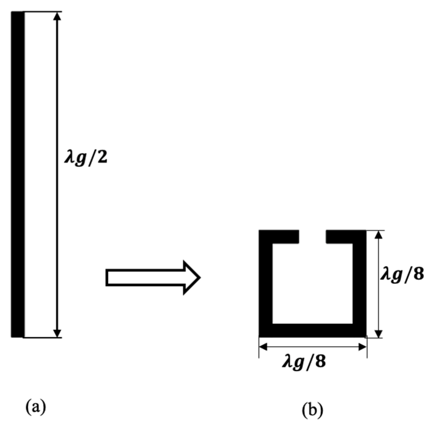
The size reduction principle employed in this work is illustrated in
Figure 1. A conventional half-wavelength (λg/2) straight microstrip resonator is folded into a square open-loop configuration with dimensions λg/8 × λg/8, achieved by bending the resonator at three points to form a near-closed square loop with a coupling gap at one end. This folding reduces the resonator side length to one-eighth of the guided wavelength at the operating frequency, yielding physically compact dimensions on the high-permittivity RT/Duroid 6010LM substrate. The standard SOLR coupling geometry is well characterized [
1,
19] and enables confident mapping from coupling coefficient to physical gap dimension for each of the nine resonators in the complete device.
The circuit configuration for the proposed triplexer is achieved by first synthesizing three identical three-pole Chebyshev bandpass filter channels from the standard normalized Chebyshev lowpass prototype filter element values of g
0 = g
4 = 1.0, g
1 = g
3 = 0.8516, and g
2 = 1.1032. These values correspond to a three-pole equal-ripple Chebyshev response, chosen to balance in-band ripple, out-of-band rejection selectivity, and physical complexity. The same prototype values are employed in the companion filtering power divider reported in [
21] from this laboratory, confirming their suitability for coupled-resonator designs on RT/Duroid 6010LM.
The design centre frequencies for the three BPF channels are 2.2 GHz, 2.6 GHz, and 3.0 GHz, corresponding to key 5G New Radio sub-6 GHz frequency allocations. Each channel is assigned a fractional bandwidth (FBW) of 3% of its respective centre frequency, with input/output characteristic impedance Z0 = 50 Ω throughout. The three channels are denoted BPF2.2, BPF2.6, and BPF3.0. These frequencies lie within the 5G New Radio (NR) frequency range 1 (FR1, 410 MHz–7.125 GHz) sub-6 GHz spectrum defined by the 3GPP standard, confirming the practical applicability of the proposed triplexer to sub-6 GHz operation.
The inter-resonator coupling coefficient M and external quality factor Q
e for each filter channel are determined from the standard coupled-resonator filter design formulations [
1,
19]. The coupling coefficient M governs the in-band ripple and bandwidth of each channel and is given by Equation (1):
The external quality factor Q
e governs the coupling between the input port and the first resonator of each channel and between the last resonator and its respective output port and is given by Equation (2):
Since M and Qe depend only on the Chebyshev prototype values and FBW, and not on the centre frequency, they are identical for all three filter channels. This design symmetry simplifies the layout, as the same coupling coefficient (M = 0.0309) and the same external quality factor (Qe = 28.387) apply to each channel, realized by physical gap and tapping dimensions scaled to the resonator size at each operating frequency.
The three BPF channels are connected to the common input port through a T-junction via transmission line stubs TL
1, TL
2, and TL
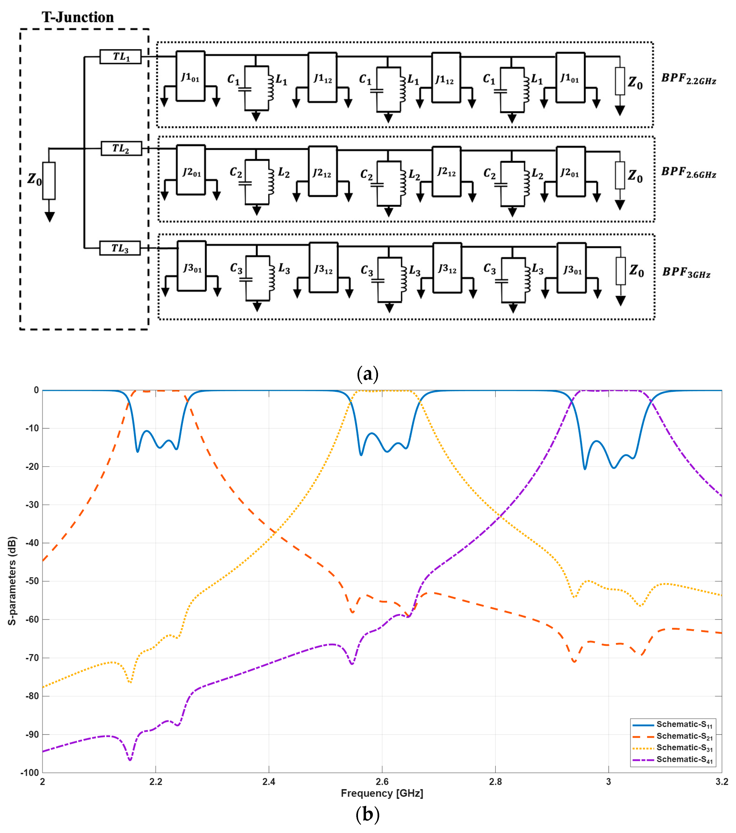
3, as shown in
Figure 2a. Each channel consists of three LC resonators coupled by admittance inverters J
01 and J
12, which represent the input/output coupling and the inter-resonator coupling, respectively. The resonator and coupling element values for each channel are summarized in the caption of
Figure 2a. The element values decrease monotonically from the 2.2 GHz channel to the 3.0 GHz channel, consistent with the inverse relationship between resonator capacitance and operating frequency at fixed impedance. The theoretical responses showing well-defined passbands at all three centre frequencies, with high adjacent-channel selectivity and low inter-channel leakage, are presented in
Figure 2b, confirming the correctness of the synthesis before proceeding to physical layout.
3. Microstrip Layout and Practical Arrangement
The triplexer design and full-wave simulation were carried out using microstrip technology with the SOLR as the fundamental building block. The guided wavelength λg and microstrip line width w for each resonator are determined from the substrate parameters and the respective resonant frequency using the standard quasi-TEM microstrip design equations [
1]. For a 50 Ω characteristic impedance on Rogers RT/Duroid 6010LM (ε
r = 10.7, h = 1.27 mm), the microstrip line width is approximately 1.14 mm, corresponding to a width-to-height ratio w/h ≈ 0.87 and an effective permittivity ε
r,eff ≈ 7.11, yielding a guided wavelength of approximately 43.3 mm at 2.6 GHz.
Each SOLR is designed to resonate at the circuit-model-specified centre frequency of its respective filter channel: 2.2 GHz, 2.6 GHz, and 3.0 GHz. The physical side length of each SOLR is λg/8 at the respective operating frequency, yielding three distinct but geometrically similar resonator dimensions. The inter-resonator coupling gaps are adjusted to realize M = 0.0309, and the feedline tapping position is adjusted to realize Q
e = 28.387, using the coupling characterization method of Hong and Lancaster [
1,
19].
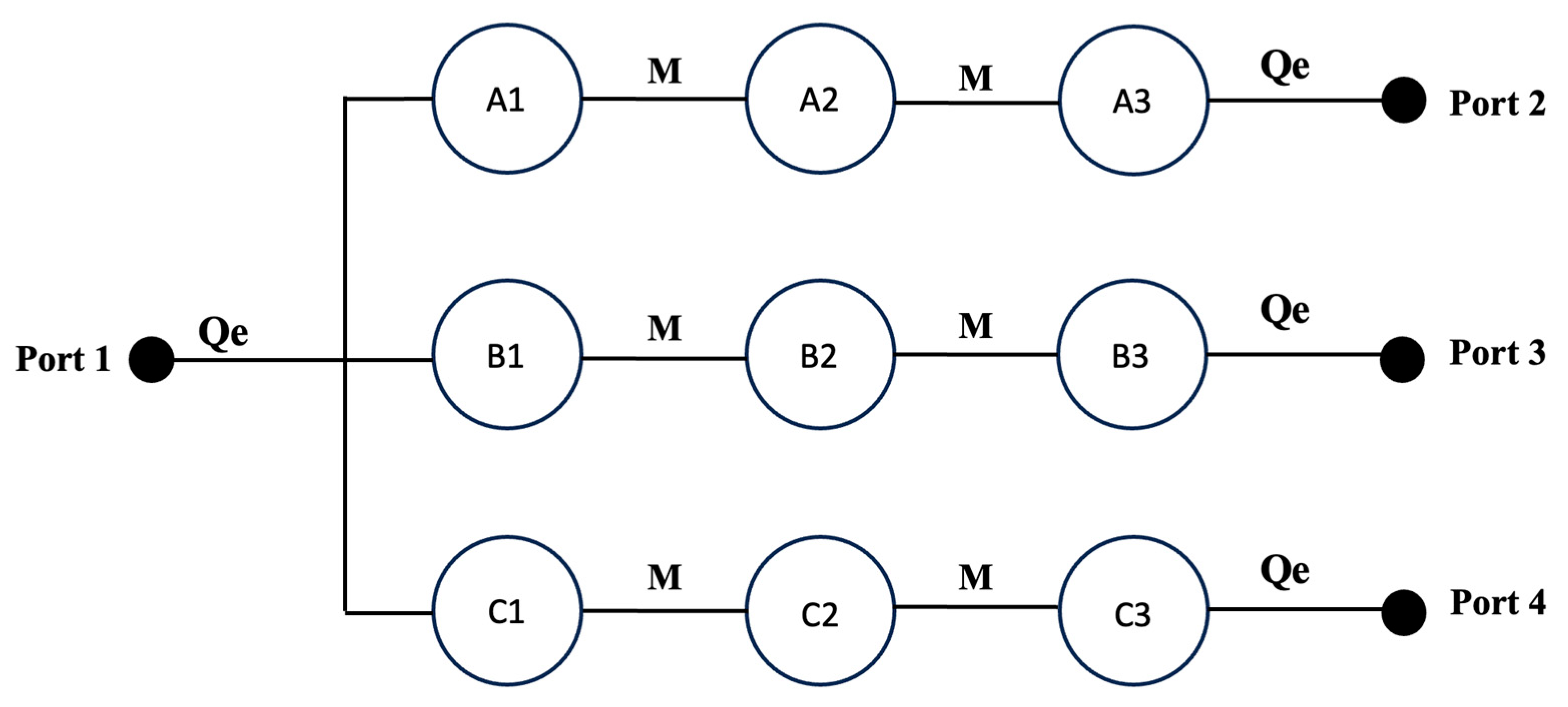
The coupling arrangement for the proposed triplexer is shown in
Figure 3. Each of the three filter channels, BPF
2.2, BPF
2.6, and BPF
3.0, is realized using three SOLRs (resonators A1–A3 for the 2.2 GHz channel, B1–B3 for 2.6 GHz, and C1–C3 for 3.0 GHz), yielding nine resonator poles across the complete device. Port 1 is the common input, with Ports 2, 3, and 4 being the channel outputs of BPF
2.2, BPF
2.6, and BPF
3.0, respectively.
The three filter channels are connected to the common input port through a T-junction via transmission line stubs TL1, TL2, and TL3. The stub lengths are selected to be approximately quarter-wavelength (λg/4) at the respective channel centre frequencies, presenting a high-impedance condition at the T-junction node for all channels except the intended one, thereby maximizing inter-channel isolation. The complete layout was constructed and simulated using Keysight PathWave Advanced Design System (ADS) Momentum EM simulation software (2025 version) on Rogers RT/Duroid 6010LM substrate (εr = 10.7, h = 1.27 mm, tan δ = 0.0023).
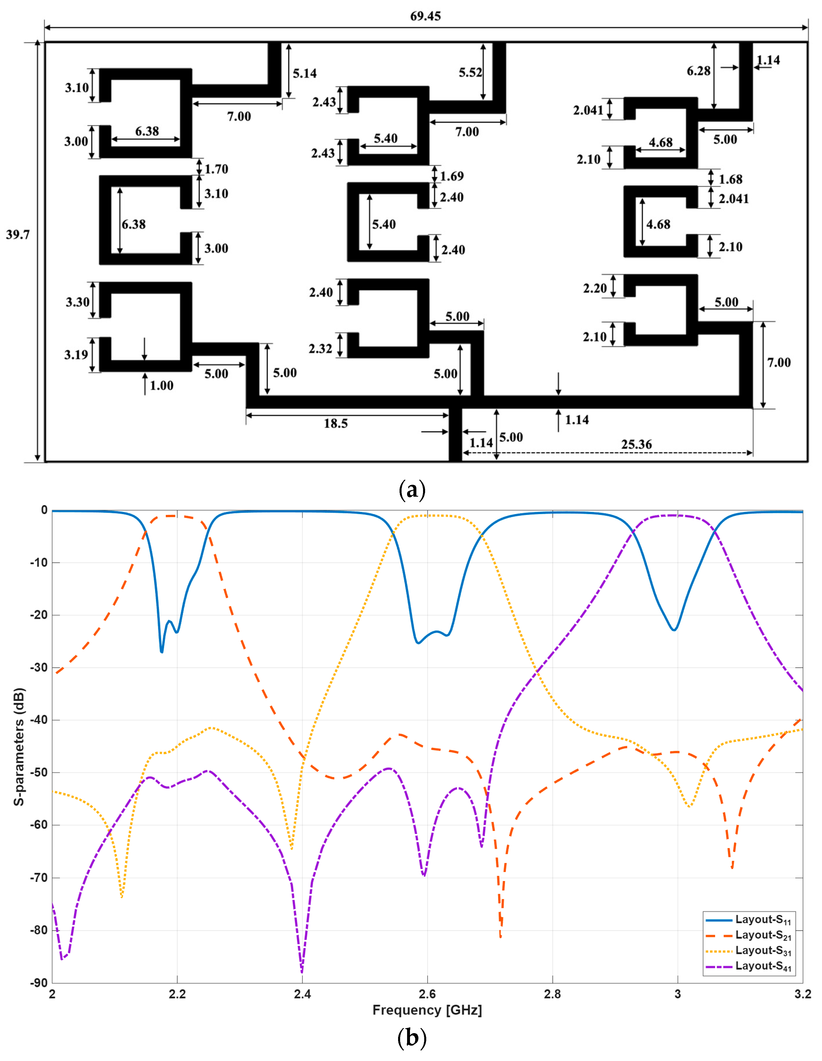
The physical dimensions of the triplexer microstrip layout, with all critical dimensions annotated in millimeters, are shown in
Figure 4a. The complete triplexer circuit occupies a footprint of 59.45 mm × 39.7 mm on the substrate which corresponds to a circuit size of 0.34λg × 0.52λg at the operation centre frequency of 2.6 GHz. While this footprint is larger than that of single-channel coupled-resonator filters, as expected for a nine-pole three-channel device, it is commensurate with the complete multiplexing functionality delivered and directly reflects the compact SOLR dimensions achievable on the high-permittivity substrate.
4. Results Analysis and Discussion
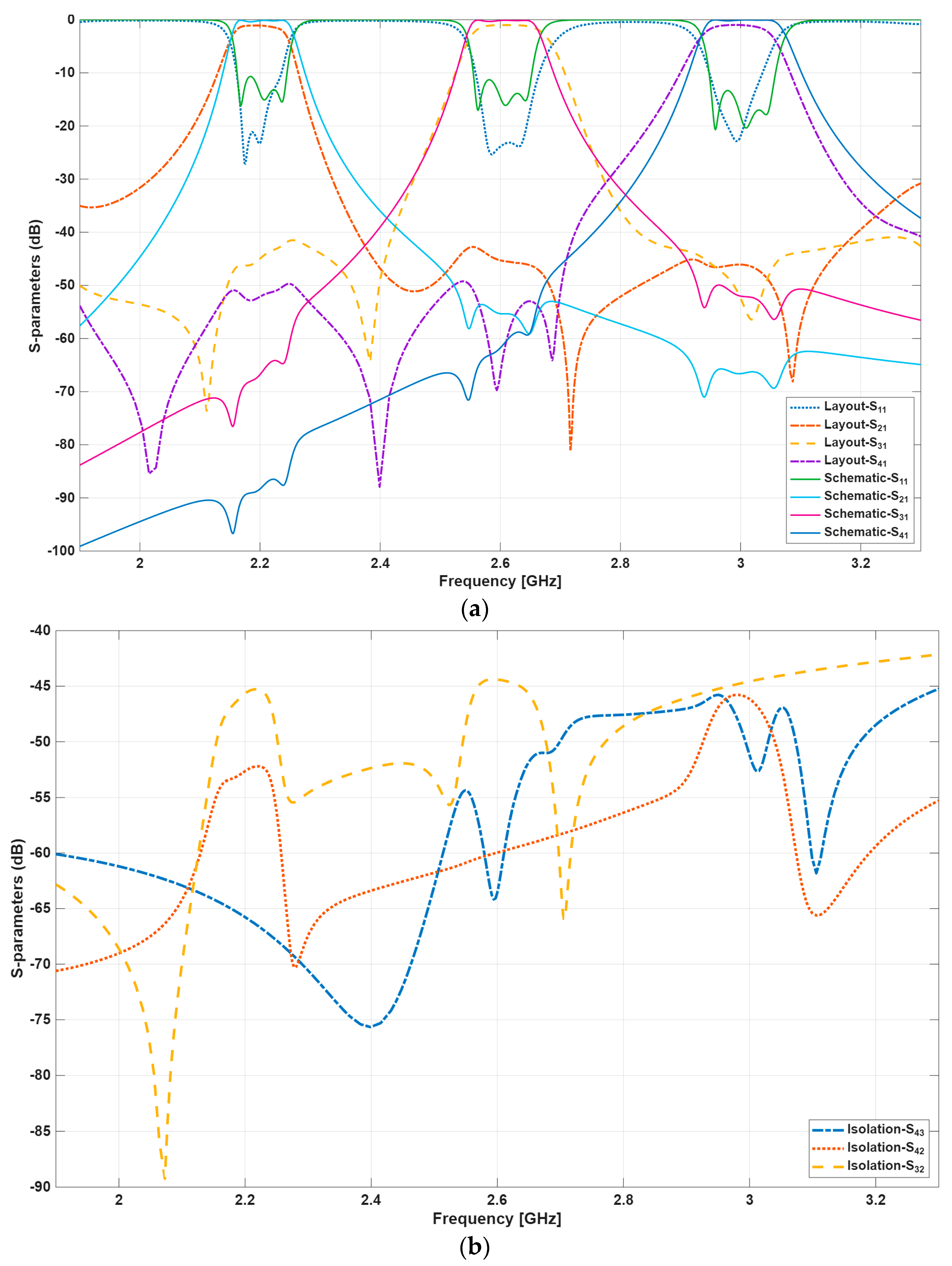
This section presents and analyses the theoretical circuit simulation and full-wave EM simulation results for the proposed microstrip triplexer. The results are jointly presented in
Figure 5a for ease of analysis and comparison. The solid-line plots represent the theoretical circuit model responses, while the dashed-line plots denote the full-wave EM simulation results obtained using Keysight PathWave ADS Momentum software (2025 version). Good agreement is observed between the theoretical and EM simulation responses across all three channels. To further validate the results in the absence of fabrication, the design was additionally simulated using two independent solvers: the circuit-level response was cross-checked in Keysight Genesys and the full-wave response in Keysight EMPro. Both were found to be in close agreement with the Keysight ADS Momentum results reported here, confirming the consistency of the design across independent numerical methods.
From the S-parameter responses of
Figure 5a, the proposed triplexer transmits at the three specified centre frequencies of 2.2 GHz, 2.6 GHz, and 3.0 GHz with EM simulation return losses of 21.1 dB, 23.1 dB, and 22.8 dB, respectively. These values comfortably exceed the 20 dB threshold generally regarded as the benchmark for well-matched microwave devices. The corresponding EM simulation insertion losses are 1.08 dB, 1.01 dB, and 0.98 dB at the respective channel centre frequencies, all below 1.1 dB, representing low-loss performance for a nine-pole device.
The isolation responses of the proposed triplexer are shown in
Figure 5b. The EM simulation isolation values, representing the transmission between channel output ports with the common input terminated, are 45.7 dB for S
32 (between the 2.2 GHz and 2.6 GHz channel outputs), 45.2 dB for S
42 (between the 2.2 GHz and 3.0 GHz channel outputs), and 45.7 dB for S
43 (between the 2.6 GHz and 3.0 GHz channel outputs). All three port-pair isolations exceed 45 dB across the relevant operating bands.
This high isolation performance is directly attributed to the T-junction integration scheme employed in connecting the three filter channels at the common input port. The T-junction stubs, dimensioned to approximately λg/4 at each channel frequency, present a high-impedance condition to all channels other than the intended one at the junction node, suppressing inter-channel signal leakage. The three-pole Chebyshev filter order further contributes to isolation by ensuring that each channel presents high rejection at the passband frequencies of the adjacent channels. This mechanism is consistent with the high isolation reported for the two-channel SOLR T-junction diplexer in [
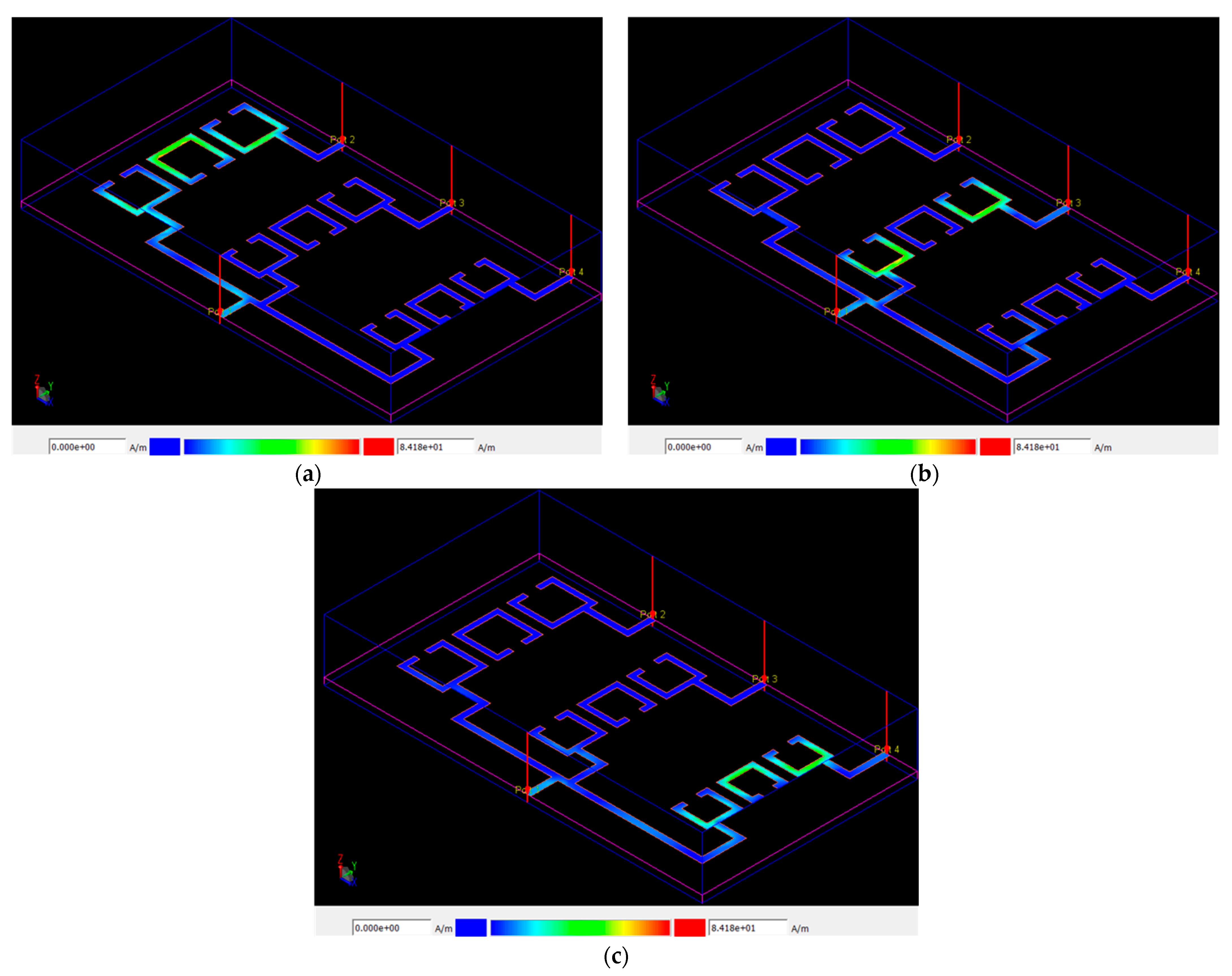
6], and the proposed design extends this performance from two to three simultaneously isolated channels. The reported high isolation is also evident from the 3D momentum visualization of the proposed triplexer in ADS as shown in
Figure 6. Looking at
Figure 6, the current distributions at 2.2, 2.6, and 3.0 GHz are well isolated. Hence, signals directed towards each of the three output ports are transmitted and received as intended. The combined effect of the junction-level isolation enforcement and the filter-order selectivity therefore yields isolation levels that are both substantially higher than, and more explicitly quantified than, those reported for comparable recent sub-6 GHz designs.
The performance of the proposed triplexer is compared against the state-of-the-art microstrip triplexers [
7,
8,
9,
10,
16,
17,
18], and refs. [
23,
24,
25,
26,
27] reported in the last decade, in
Table 1. The comparison covers operating frequencies, filter order, circuit size, transmission line technology, return loss, insertion loss, and inter-channel isolation. The isolation column is included specifically to contextualize the principal contribution of this work, as it is reported in only a minority of recent published triplexer studies.
As evident from
Table 1, the proposed design is among the few microstrip triplexers in the comparison to report an explicit inter-channel isolation figure for all three port pairs, achieving > 45.2 dB. The only comparator achieving higher isolation is [
18], which targets substantially higher millimeter-wave frequencies (5.0/16.6/42 GHz) using a specialized miniaturized architecture; this confirms that very high isolation is achievable in principle, but it is not commonly demonstrated and even less reported in the 1–4 GHz sub-6 GHz range directly relevant to the present work. Among the sub-6 GHz comparators, the next-highest reported isolation is approximately 20 dB [
7,
9], more than 25 dB below the isolation achieved here. The insertion loss of 0.98–1.08 dB is competitive for a nine-pole three-channel device on RT/Duroid 6010LM, and the return loss of 21.1–23.1 dB exceeds the 20 dB benchmark across all three channels and the values reported in [
7,
8,
9]. Several of the more recent lowpass-bandpass triplexer designs in
Table 1 report lower per-channel insertion loss than the present work; this reflects, in part, the lower filter order typically used in their bandpass channels and the absence of a dedicated, electromagnetically separated junction structure, both of which were deliberately retained here to maximize inter-channel isolation, which is the principal figure of merit targeted in this work.