Article

Designing Before Folding: Morphological Design Principles for Thermally Formed Passive Adaptive Grippers


Department of Mechanical Engineering, SCE—Shamoon College of Engineering, Ashdod 77245, Israel
*
Author to whom correspondence should be addressed.
Designs 2026, 10(4), 75; https://doi.org/10.3390/designs10040075
Submission received: 31 May 2026 / Revised: 11 July 2026 / Accepted: 17 July 2026 / Published: 21 July 2026

Abstract

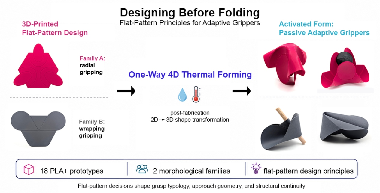
This qualitative study develops morphological design principles for thermally formed passive adaptive grippers within an accessible 4D-printing approach. A practice-based morphological exploration was conducted through 18 PLA+ prototypes fabricated by Fused Deposition Modeling and thermally formed through controlled hot-water immersion. The study treats the two-dimensional pre-forming sheet geometry as the central design variable and examines how variations in flat-pattern organization affect the activated three-dimensional gripper. This shifts attention from optimizing a single predefined gripper toward understanding how form variations generate design knowledge. The prototypes were organized into two morphological families: a convergence-based radial gripping family and a guided cylindrical wrapping family. Functional and morphological readings of the catalogue showed that flat-pattern decisions shape grasp typology, functional role distribution, approach geometry, structural continuity, and the behavioral envelope of the activated form. The study proposes seven morphological design principles linking flat-pattern operations to three-dimensional gripping consequences, while also showing that the two families form a continuum of morphological possibilities rather than discrete categories. Across the prototype lineage, design knowledge accumulates through comparison and can be recombined into more resolved configurations. This paper offers a planning vocabulary for developing passive adaptive gripping structures before performance optimization or application-specific engineering begins.

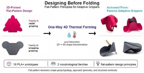
Graphical Abstract

1. Introduction

Research on adaptive and soft grippers has largely discussed form in relation to functional performance, including grasping capability, compliance, actuation strategy, and task-specific versatility [1,2,3,4]. Within this framing, the three-dimensional form of the gripper is typically evaluated for what it enables, rather than examined as an independent site of design inquiry.
This paper proposes a different entry point. When a gripper is fabricated as a flat sheet via FDM and subsequently thermally formed into its operational three-dimensional geometry, within a broader 4D-printing paradigm of post-fabrication shape transformation [5,6], the flat pattern is not merely a manufacturing convenience. It is a designed artifact in its own right. The decisions made within it, including which fold-line geometries, which cutouts, and which fold-direction encodings, are shown here to govern not only the three-dimensional character of the gripper but also its gripping behavior: the typology of grasp, the distribution of functional roles across the surface, the character of pre-contact approach geometry, and the boundaries of observed form behavior.
This relationship is treated as a form-language methodology in which the designer composes flat-pattern geometry as a primary design act, and studies the three-dimensional consequences through physical prototyping. This methodology is rooted in practice-based and design-oriented research traditions [7,8]. The approach is also in dialogue with origami-inspired engineering [9] and with origami-based grasping systems in which flat-pattern geometry is developed in relation to a desired motion or functional outcome [10]. The present work proceeds in the opposite direction: from flat-pattern composition to discovered three-dimensional outcomes.
The study is positioned at the intersection of four research areas: adaptive and soft gripper design, 4D printing and thermally activated shape morphing, origami-inspired engineering, and practice-based design research. Together, these fields provide the technical and methodological context for examining flat-pattern composition as a source of morphological design knowledge.

1.1. Adaptive and Soft Grippers

The foundational argument for soft and adaptive grippers rests on the concept of morphological computation [2]: compliance embedded in material and geometry can reduce the burden placed on sensing, modeling, and explicit control. Shintake et al. [1] provide a systematic taxonomy of soft grippers organized around actuation, controlled stiffness, and controlled adhesion. Chan and Scharff [11] offer a recent overview of passive adaptive grippers and show that fully passive systems combining prehension, retention, and release remain scarce within the current literature.
Deimel and Brock [3] demonstrate through compliant “soft synergies” that mechanical compliance can reduce the need for explicit control in grasping. This principle is relevant to the present study, which examines how gripping behavior may likewise emerge from designed geometric organization rather than from active control.

1.2. 4D Printing and Thermally Activated Shape Morphing

Tibbits [5] introduced the concept of 4D printing, additive manufacturing in which a printed object transforms in response to a stimulus. Momeni et al. [6] reviewed this field across stimulus types, responsive materials, and structural strategies. Biomimetic 4D-printing studies further demonstrate how printed material organization can encode stimulus-responsive shape change, showing that transformation is governed not only by material choice but also by programmed spatial arrangement [12]. Importantly, reversibility is not a defining requirement of all 4D-printing systems. The literature distinguishes between one-way 4D printing, in which a printed structure undergoes a programmed transformation after stimulation, and two-way or reversible 4D printing, in which the printed structure can repeatedly transition between configurations under appropriate stimuli [13,14]. Within this broader landscape, the present study focuses on an accessible one-way route: flat FDM-printed PLA sheets that are thermally formed into operational three-dimensional gripper geometries through a one-time forming step. Unlike conventional thermoforming of a geometrically undifferentiated sheet, the forming process examined here is guided by fold lines, grooves, cutouts, and directional relationships that are encoded in the printed flat pattern before heating.
Van Manen, Janbaz, and Zadpoor [15] showed that standard FDM printers can program 2D-to-3D shape-shifting in single-material PLA prints through printing direction and pattern design, demonstrating that planar fabrication decisions can encode predictable three-dimensional behaviors. More broadly, studies on programmable flat matter and 2D material programming show that two-dimensional precursors can be intentionally encoded to guide subsequent three-dimensional shaping, reinforcing the relevance of the pre-formed state as an active design domain rather than a neutral manufacturing intermediate [16,17]. Saptaji et al. [18] characterize how thickness, infill percentage, print speed, and thermal parameters jointly determine shape-recovery ratio in PLA structures. Mechanics-based reviews of 4D printing similarly emphasize that programmed transformation depends not only on material response, but also on geometric and structural design strategies that pre-embed deformation into printed precursors [19]. Demoly et al. [20] identify a broader methodological gap in 4D printing: while material and process research has advanced rapidly, systematic design methods for developing shape-transforming products remain comparatively underdeveloped. The present study addresses one specific aspect of that gap by treating flat-pattern geometry as a primary design variable.

1.3. Origami-Inspired Engineering and Flat-Pattern Thinking

Meloni et al. [9] review origami engineering comprehensively, showing that fold-pattern geometry can encode deployability, stiffness tunability, energy absorption, and kinematic transformability. One recurring direction within this literature is inverse design: beginning with a desired three-dimensional configuration, motion, or functional outcome and deriving a suitable crease pattern. The present work takes a different orientation, beginning from flat-pattern composition and studying the three-dimensional behaviors that emerge; the two approaches are complementary.
Recent origami grippers demonstrate the field’s technical maturity. Liu et al. [21] present a gripper with rapid kinematic state change. Hou et al. [22] develop a bistable shape-adaptive gripper capable of grasping. Cao et al. [4] develop an optimization-based inverse design method for versatile grasping. Yasuda et al. [10] demonstrate bistable self-adaptive origami grasping motions that can be triggered by object contact and retain capture without requiring continuous external power. Comparatively less attention has been paid to systematic exploration of the flat-pattern design space itself, specifically to how variation in flat geometry propagates into variation in grip character independent of a pre-specified behavioral target.

1.4. Practice-Based Design Research and Morphological Knowledge Generation

Vaughan [7] situates practice-based design research as a legitimate mode of inquiry grounded in iterative making, reflection, and the generation of knowledge through practice. Zimmerman et al. [8] articulate Research through Design as a methodological framework in which designed artifacts function not merely as outcomes, but as vehicles for producing and communicating transferable research knowledge. Together, these frameworks support a morphological, non-quantitative study of gripper families focused on transferable form principles, not engineering performance data.
Hekkert and van Dijk [23] provide a design-theoretical basis for treating form as an intentional and meaning-bearing outcome of designerly judgment, rather than as a neutral by-product of technical resolution. In the present study, this orientation is applied to gripper families through serial morphological exploration: flat-pattern variations are developed, compared, and reflected upon not only to produce coherent families of objects, but to extract design principles, namely transferable statements about how flat-pattern decisions govern gripping behavior.

1.5. Research Gap, Aim, and Scope of the Present Study

Despite growing attention to adaptive grippers, 4D-printed shape transformation, origami-inspired mechanisms, and practice-based design research, the flat pattern itself has received comparatively limited systematic treatment as an independent design variable in the study of gripper morphology. In particular, several relationships remain insufficiently understood: how flat-pattern organization generates distinct grasp typologies; how different regions of a flat sheet can be assigned distinct functional roles; how geometry can produce pre-contact guidance behavior rather than only post-contact compliance; and how transferable design principles can be extracted from systematic morphological exploration without requiring an engineering optimization framework.
This study addresses that gap through a practice-based morphological exploration of thermally formed FDM grippers. The aim is to examine how variations in flat-pattern geometry generate three-dimensional gripper morphologies and to extract transferable design principles for planning passive adaptive gripping structures. The study is positioned as a design-oriented morphological inquiry rather than as an engineering performance study. Each prototype is therefore examined through a combined functional and morphological reading: functionally, by asking whether it produces a recognizable gripping action and what character that action takes; and morphologically, by asking whether the activated form exhibits an integrated geometry, intention, and a legible relationship to its flat-pattern origin.
The grippers examined here are passive in operation. Thermal forming is treated as a one-time fabrication step; once the PLA+ has been set into its operational geometry, gripping occurs through the formed geometry itself, with no actuation required during use. In this study, “passive adaptive” refers to grippers that are thermally formed once into a fixed operational geometry and subsequently interact with objects without repeated actuation, sensing, or control. Their adaptivity is understood in morphological design terms: the extent to which the formed geometry can receive, guide, partially conform to, or support objects through its shape, rather than through an actively controlled gripping mechanism. The principal contribution of the study is a set of morphological design principles that position the flat pattern not only as a fabrication intermediate, but as a design space for organizing gripping behavior before forming begins.

2. Materials and Methods

This study was conducted as a practice-based morphological design exploration. A series of thermally formed FDM grippers was developed and compared in order to examine how variations in flat-pattern organization influence three-dimensional gripping form and behavior. The section below describes the design variables, fabrication process, prototype organization, and comparative reading method used in the study.

2.1. The Flat Pattern as Primary Design Variable

The methodological premise of this study is that, in thermally formed FDM grippers, the flat two-dimensional print pattern serves as the primary site of design decision-making. The flat pattern is treated here as the principal variable through which the activated three-dimensional gripper is shaped. Key formal properties of the resulting gripper, including its number of fingers, spatial orientation, curvature character, surface continuity, and the presence or absence of guided-approach geometry, are investigated as consequences of decisions made in the flat state.
The specific flat-pattern variables explored are: (a) base polygon type, hexagon or triangle; (b) internal fold-line geometry, including arcs, ellipses, and straight lines implemented as locally weakened groove geometries; (c) material subtraction, defined as the removal of regions from the flat sheet; (d) fold-direction encoding, namely whether internal fold lines point toward polygon corners or edge midpoints; and (e) groove density, defined by the number of parallel grooves along a fold line. These variations were treated not merely as local formal adjustments, but as probes into broader relationships: the emergence of distinct grasp typologies, the allocation of functional roles across the sheet, the preservation or disruption of structural continuity, and the appearance of pre-contact guidance geometries.

2.2. Fabrication and Thermal Forming

All prototypes were printed using commercial PLA+ filament on a standard FDM desktop printer (Bambu Lab X1 Carbon, Shenzhen Tuozhu Technology Co., Ltd., Shenzhen, China), using a 0.2 mm layer height. The slicer infill setting was left at the default value of 15%. Given the thin 0.8 mm sheet geometry, and the 0.2 mm layer height, the sheets were printed as four solid layers, with no internal infill region generated in practice, making the parts functionally equivalent to fully filled thin sections. As a result, the nominal infill setting had no practical effect; local bending behavior was governed by the designed fold-line/groove geometry. Thermal forming was performed by immersing the flat-printed sheet in hot water at 60–70 °C for approximately 30–60 s, until the material became pliable. The water was heated in a 1600 mL Pyrex glass container on a controlled electric hot plate (HP-4, Fried Electric, Haifa, Israel), and the temperature was monitored with a thermometer during forming. The sheet was then shaped manually according to the designed fold-line layout. In some cases, simple reference objects or previously formed models were used to guide curvature during cooling, but no controlled mechanical forming fixture was used. The formed geometry was held until cooling, approximately 90 s in ambient air. The main fabrication and thermal-forming parameters used across the prototype catalogue are summarized in Table 1.
This forming process is treated as a one-time manufacturing step. Once cooled, the PLA+ retains the formed geometry under ambient conditions. During use, no further actuation is applied; gripping behavior arises from the formed geometry, its local compliance, and the way an object is inserted into or guided by the gripper.

2.3. Family Structure and Lineage Diagram

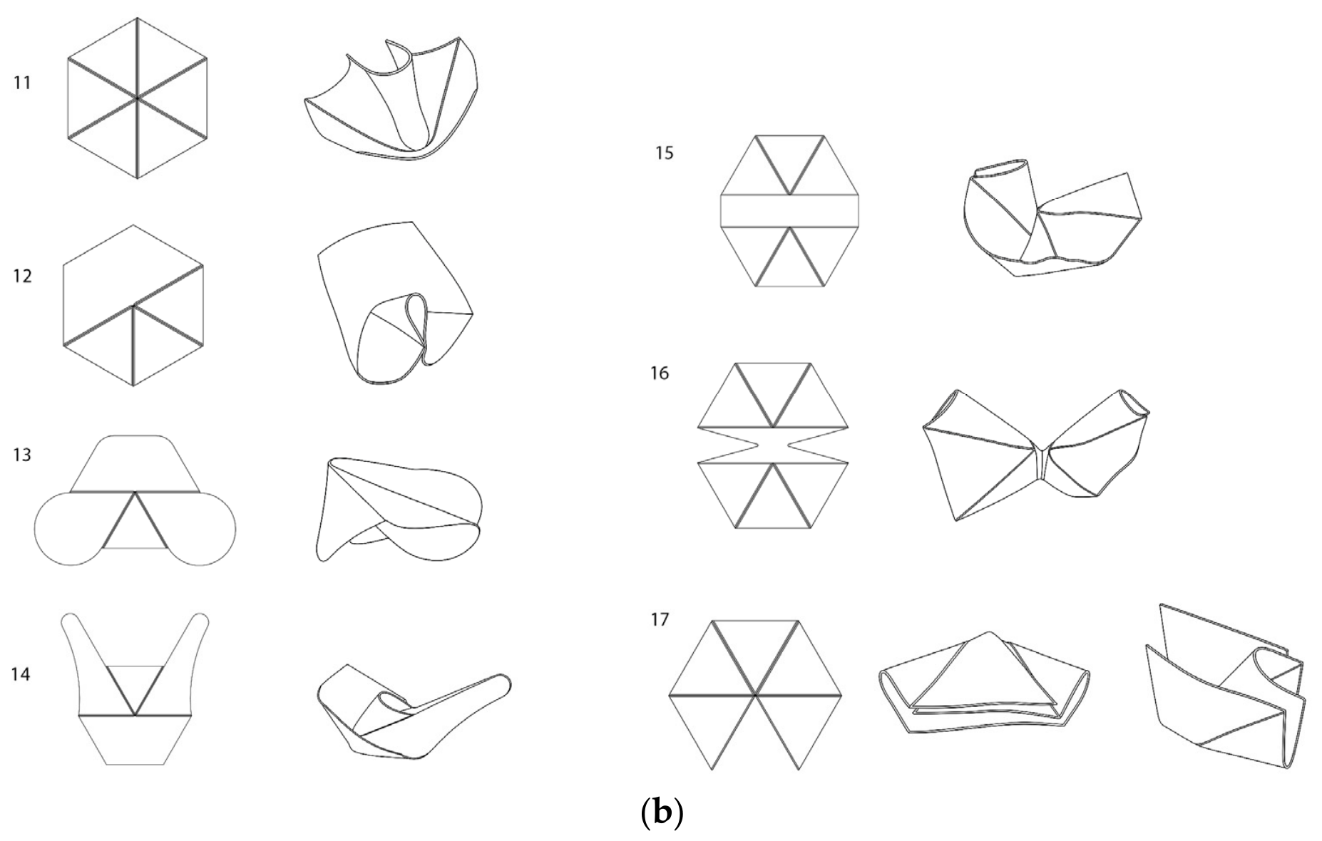
The 18 prototypes are organized into two principal families, defined by their base flat-pattern geometry and by the distinct grasp typologies that emerge from it. A visual catalogue of all prototypes is provided in Appendix A. Figure 1a,b present the lineage diagrams of Family A and Family B, respectively, mapping flat-pattern origins to activated forms and indicating derivation relationships between models.

2.4. Functional and Morphological Reading

Each prototype was examined through a combined functional and morphological reading. Functionally, the analysis considered whether the formed geometry produced a recognizable gripping action and the character of that action, such as enclosing, pinching, guiding, or stabilizing. Morphologically, prototypes were compared in terms of the legibility of their transformation from a flat-pattern to three-dimensional form, the distribution of functional roles across the sheet, the continuity or fragmentation of the activated surface, and the emergence of pre-contact guidance geometries. This comparative reading formed the basis for identifying recurring form principles across the families.
The comparative reading was structured around a common set of qualitative observational dimensions: the flat-pattern operation introduced in the model; the activated three-dimensional morphology produced after thermal forming; the observed gripping, receiving, guiding, or stabilizing behavior, where applicable; the main limitation or trade-off observed during handling or object insertion; and the local design insight derived from comparison with preceding or related models. These dimensions were used to structure the cross-prototype synthesis presented in Section 3.3 and to support the morphological design principles developed in Section 4.
The evaluation was qualitative and observational rather than a quantitative mechanical benchmarking procedure; therefore, functional terms used in the analysis refer to observed behavior under manual handling and representative object-insertion conditions, not to measured gripping force, load capacity, or success rate. Accordingly, expressions such as stable support, reduced gripping support, guided approach, coherent activated geometry, and structurally continuous gripping regions are used as qualitative descriptors of observed form–behavior relationships, rather than as quantitative performance categories. Representative spherical objects of different diameters and cylindrical objects of different diameters and lengths were used during the observational assessment to examine receiving, gripping, guiding, and stabilizing behavior. The objects were selected to represent the main interaction geometries relevant to the prototype families: spherical objects for radial gripping and cylindrical objects for wrapping and guided-insertion behavior. Because the study was not designed as a fixed-count trial protocol, these observations were not converted into success rates. Instead, stable support was recorded qualitatively when an object remained positioned within the activated geometry during manual handling, whereas reduced or weak support was recorded when object insertion was obstructed, contact was limited, or the object was easily displaced.
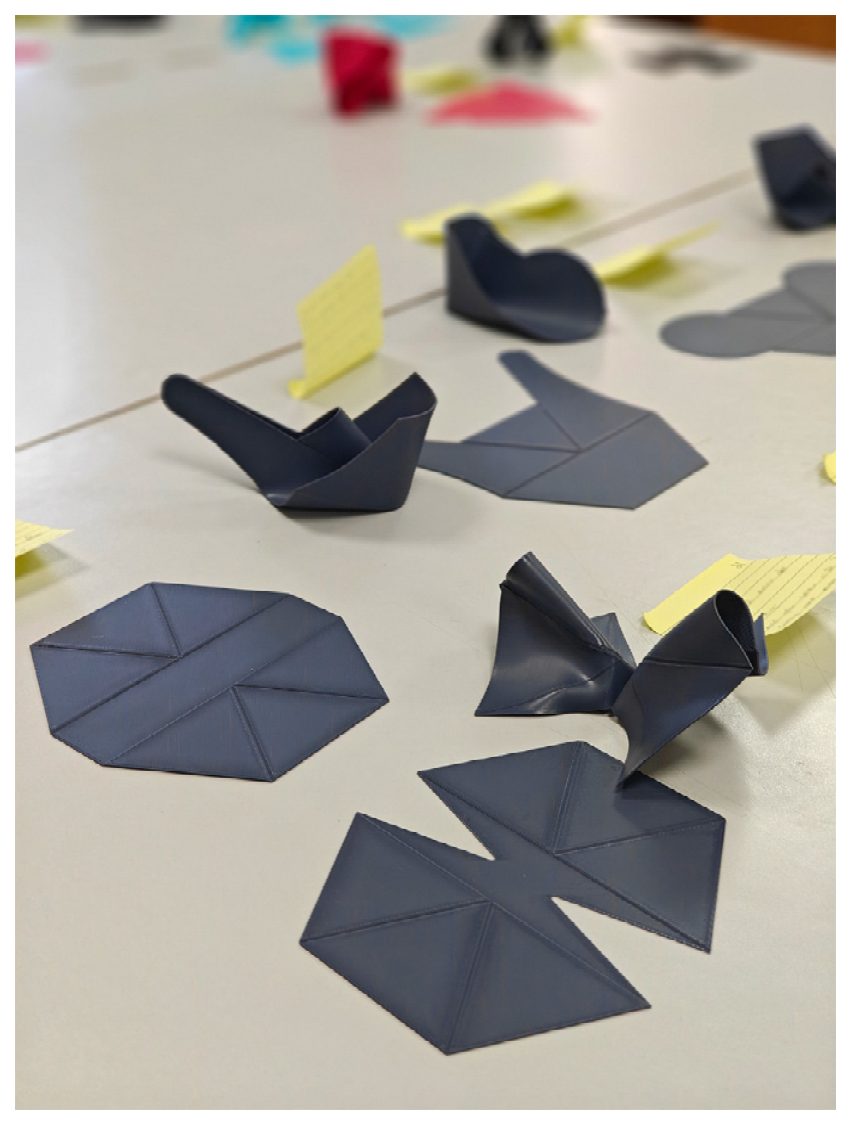
To support this comparative reading, prototypes were arranged as a physical catalogue in which flat patterns and thermally formed models could be compared across the design lineage. Figure 2 shows the catalogue environment used during the practice-based exploration process. Because the figures are intended to support morphological comparison rather than dimensional measurement, images in multi-panel figures are not shown at a uniform scale unless otherwise stated.

2.5. Materials, Data, and Design Documentation Availability

The study does not report a large quantitative dataset or computer code. The research materials consist of flat-pattern drawings, prototype photographs, activated forms, and the morphological catalogue presented in the article. Additional design documentation related to selected prototypes may be made available by the corresponding author upon reasonable request, subject to practical file availability and intellectual property considerations.

2.6. Use of Generative Artificial Intelligence

Generative artificial intelligence tools were used to support English language editing, wording refinement, and manuscript preparation. They were not used to generate flat-pattern geometries, prototype forms, figures, data, or design principles. All research design, prototype development, morphological interpretation, and design principles were developed by the authors.

3. Results

3.1. Family A: Convergence-Based Radial Gripping

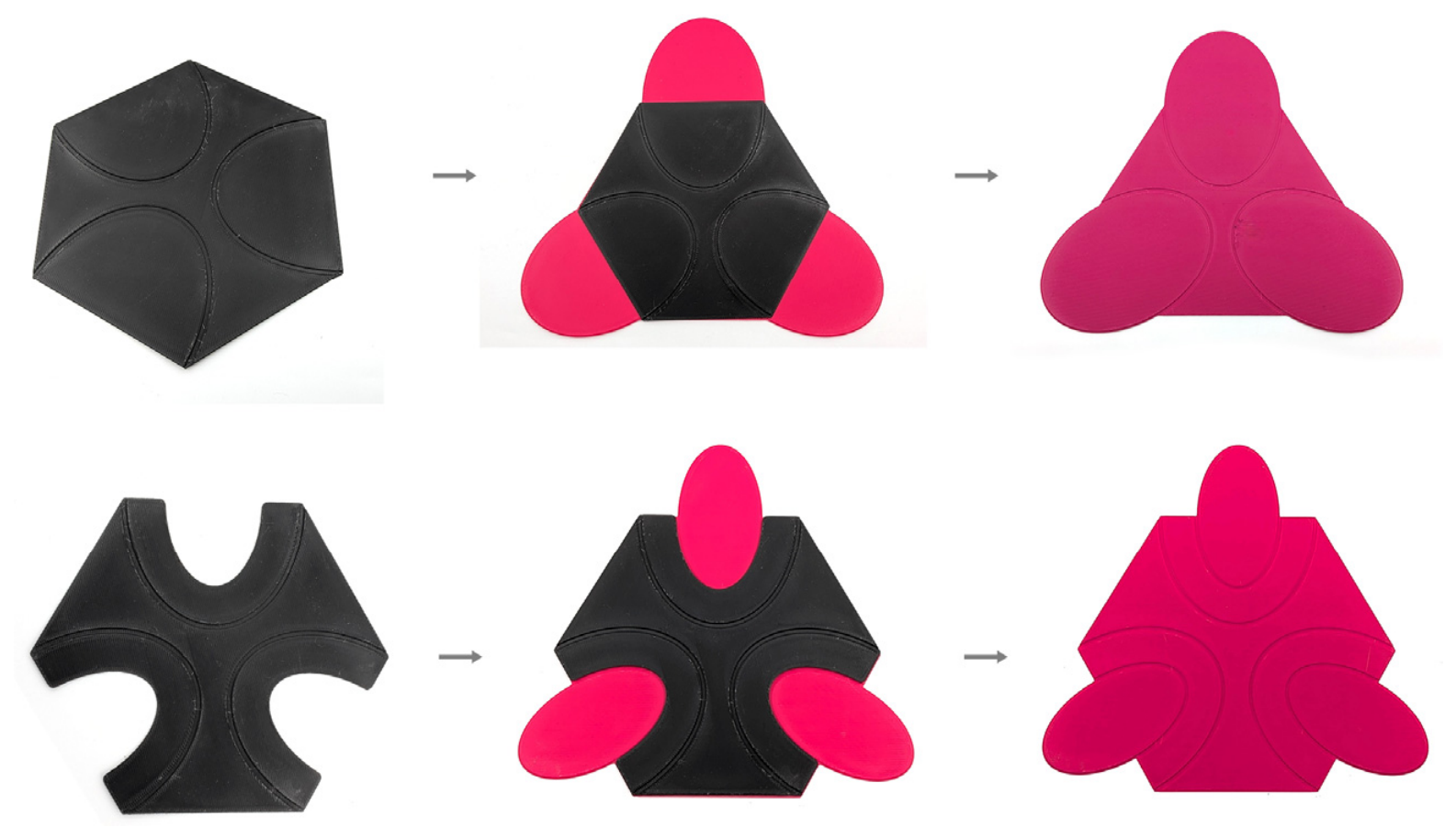
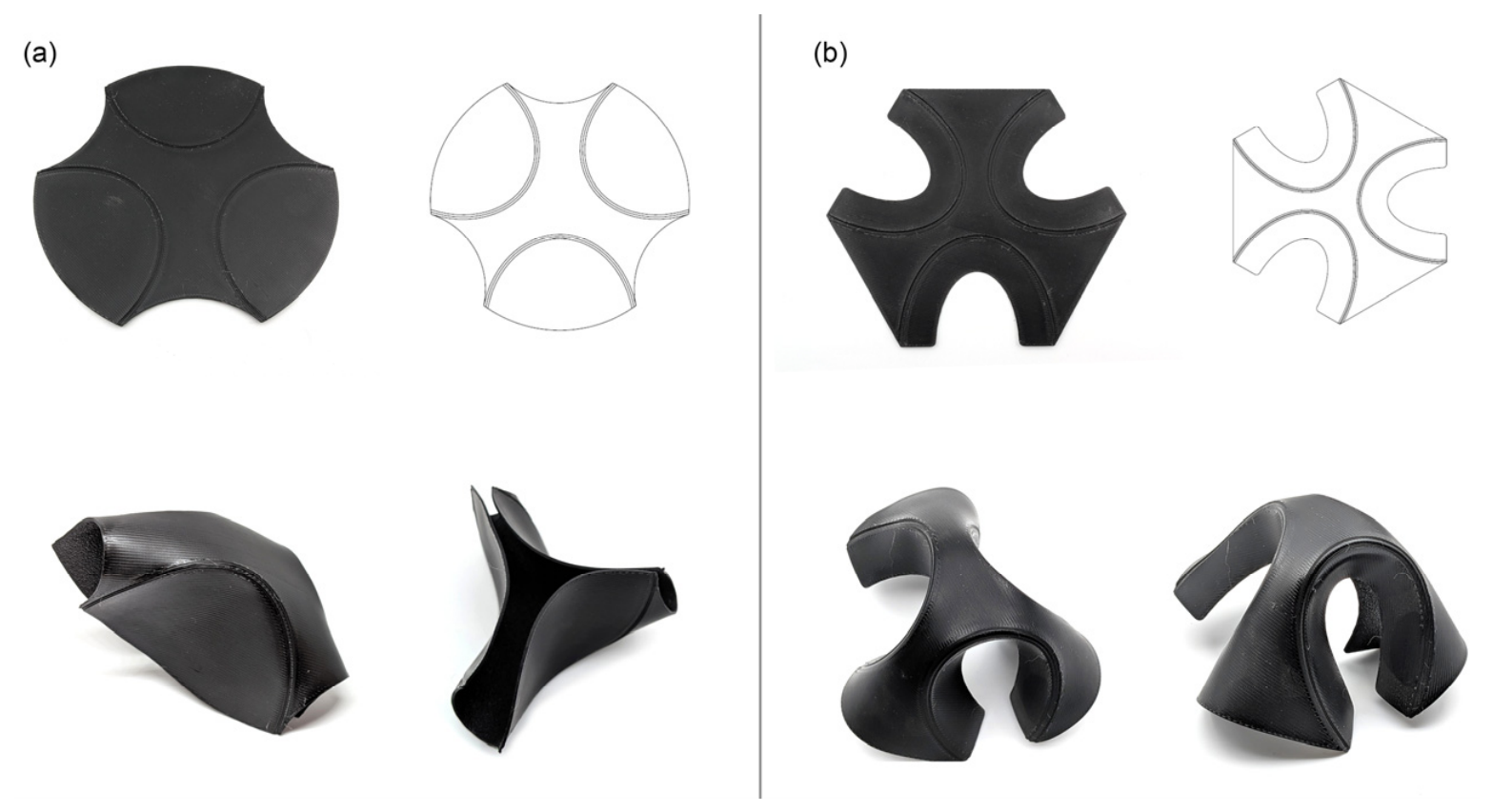
Family A is referred to here as the “classic” adaptive gripper typology: a three-armed or three-fingered form in which radially symmetric elements close inward upon thermal forming to create a central grip zone. The word “classic” refers strictly to the structural arrangement, three elements and radial symmetry, not to the forms that result from it, many of which are far from conventional. The family originates from a regular hexagonal flat pattern and develops across eleven models through systematic variation of internal fold-line geometry, material subtraction, base polygon, and fold direction. The lineage is not strictly linear; it branches at multiple points, with each branch testing a specific formal hypothesis. Figure 3 illustrates two representative derivation paths within Family A, showing how specific changes in the flat pattern produce distinct activated geometries and gripping behaviors.

3.1.1. Model 1, Base Hexagon with Arc Curves

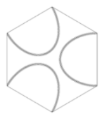
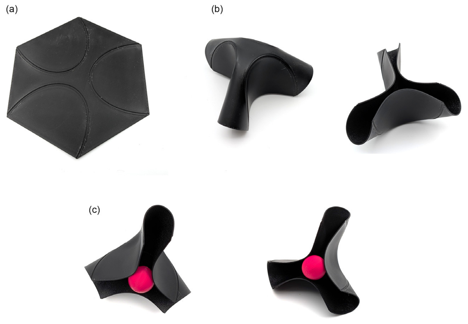
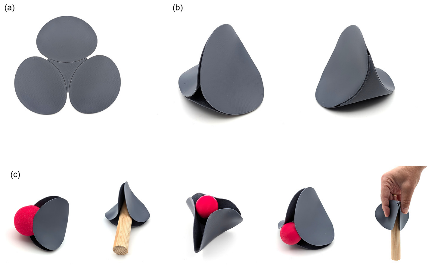
Model 1 establishes the foundational typology of Family A. Three arc curves spanning between alternate hexagon edges bias the sheet toward inward folding upon thermal forming, producing a three-finger form. Two formal problems are immediately visible: terminal spikes at each fingertip where arc geometry terminates at hexagon corners, and a compressed central convergence zone. Both persist in any model that directly inherits this arc-to-corner geometry, motivating exploration of alternative internal fold-line logics. Figure 4 shows the flat pattern, activated form, and initial gripping behavior of Model 1.

3.1.2. Models 2(1B) and 3, Body Subtraction Branch

Models 2(1B) and 3 introduce material subtraction into the structural body of the gripper, the central structural region. Figure 5 compares the body-subtraction variants and their activated forms. The flat patterns acquire an open, architecturally interesting character. However, the subtraction compromises structural integrity: the regions removed from the central body are also regions required for maintaining the gripping form under contact. This establishes the subtraction location principle: material removed from the structural body reduces gripping support while external form may improve.

3.1.3. Model 4(2A), Hybrid Synthesis

Model 4(2A) combines body subtraction from 2(1B) with discrete finger elements from the Model 2 branch. Figure 6 shows the hybrid configuration and its activated geometry. Some gripping behavior is recovered, but the formal result is instructive: independently applied formal operations produce a pattern that reads as additive assembly rather than formal unity. A single governing geometric logic that integrates all operations is necessary for a coherent activated geometry.

3.1.4. Model 5, Ellipse Completion: A Formal Turning Point

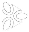
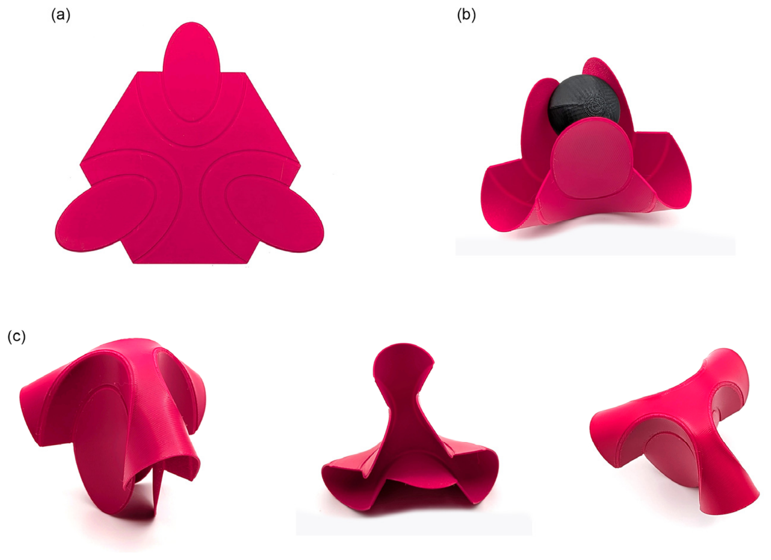
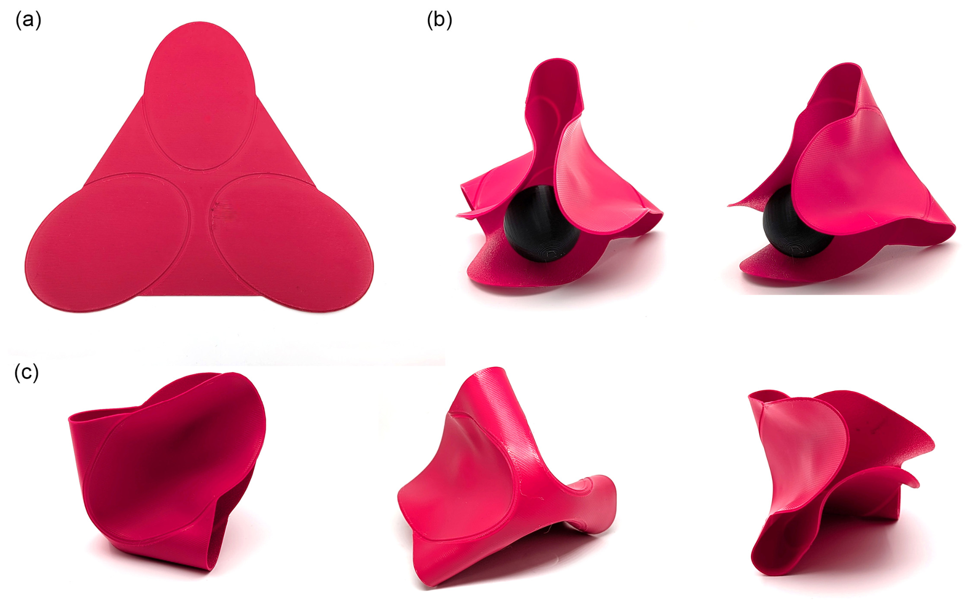
Model 5 represents the most significant formal insight within Family A. Rather than arc segments terminating at hexagon edges, the flat pattern is organized around three complete ellipses whose perimeters encode fold lines. Figure 7 shows the transition from completed ellipse geometry in the flat pattern to the smoother activated three-finger form. The morphological consequence is substantial: completed ellipse geometry naturally rounds the fingertips, eliminating all spike artifacts, and the three-finger form exhibits smooth, continuous curvature throughout. Physical examination showed that even partial contact with two of three fingers was sufficient for stable support during manual handling, a property that suggests relevance for conditions of imprecise object placement. This suggests that formal continuity in the flat pattern affects not only visual resolution but the quality and redundancy of the resulting contact geometry.

3.1.5. Models 6 and 7, the Fold Direction Principle

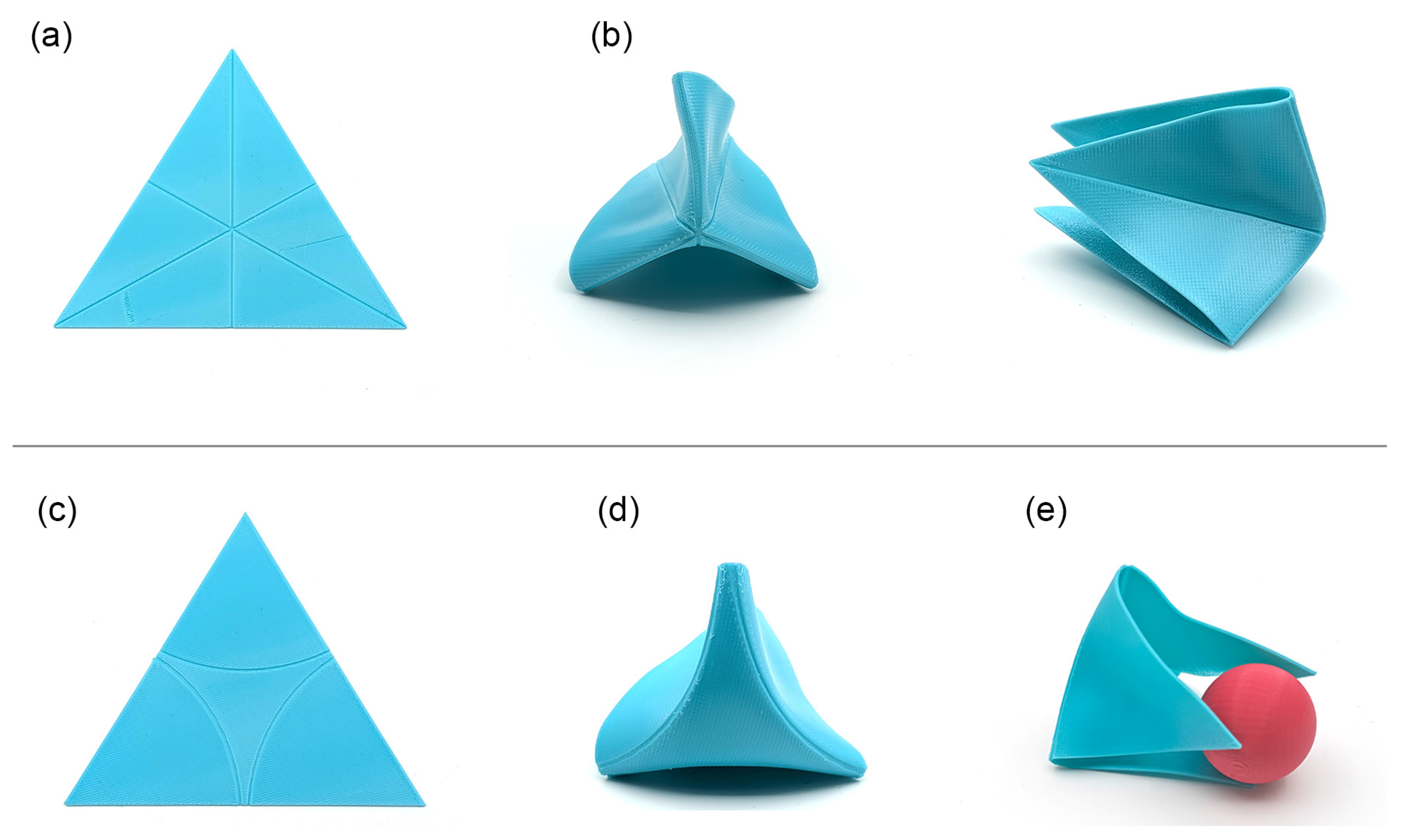
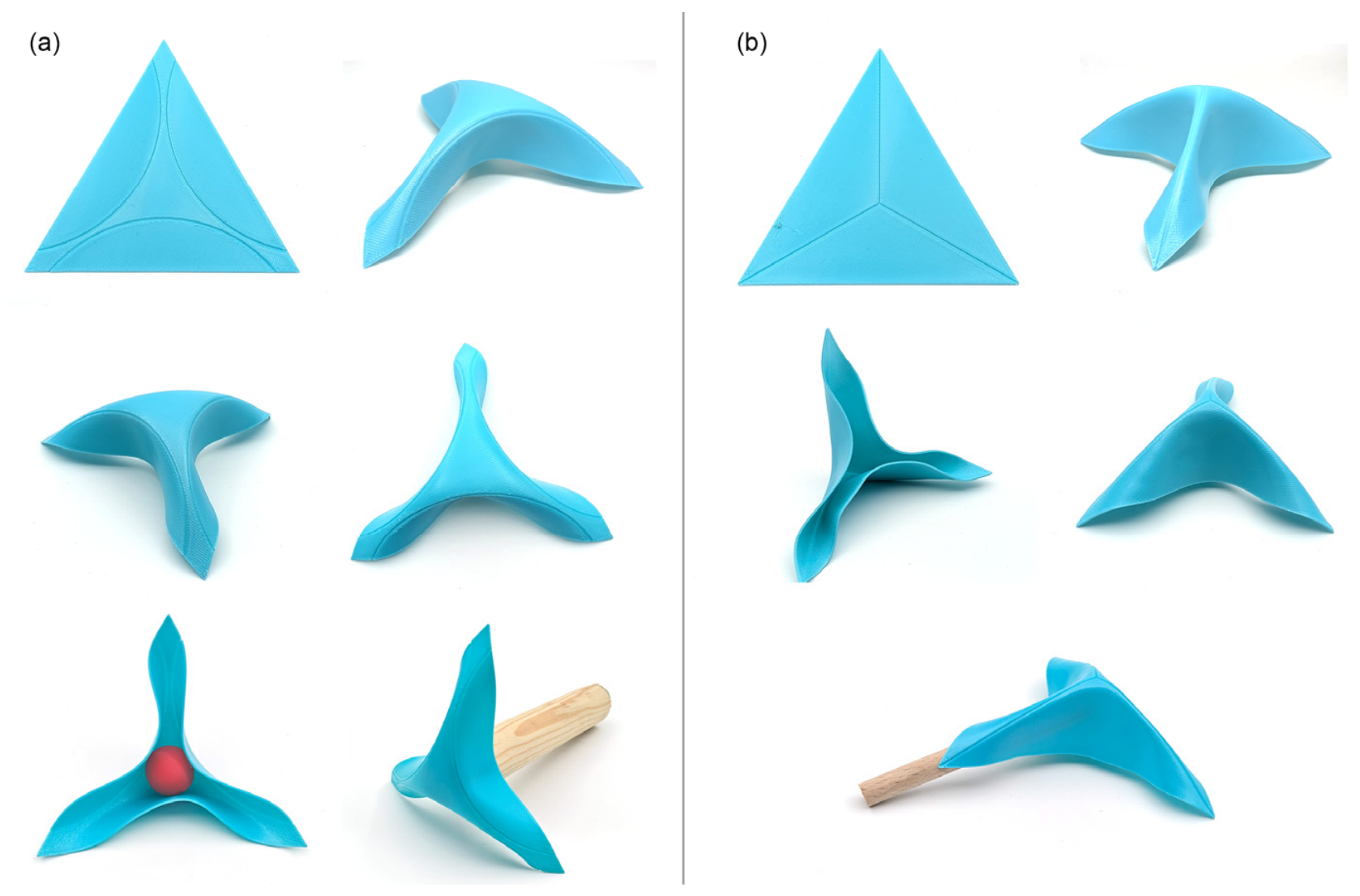
Models 6 and 7 constitute a controlled formal comparison that isolates fold direction as the single variable. Figure 8 compares the corner-directed and edge-directed triangular configurations. Both models use an equilateral triangle as the base polygon and carry three internal fold lines; all other parameters are equivalent. Model 6 uses corner-directed fold lines, producing a tall, convergent, vertically oriented gripper. Model 7 uses edge-directed concave arcs, producing a wide, open, horizontally oriented form. This single formal decision changes the entire spatial character of the gripper: whether objects are approached from above or from the side, and whether the grip zone is open or enclosed. No other flat-pattern variable tested produced an equivalent qualitative shift.

3.1.6. Model 8, Groove Economy and Compound Fold-Line Geometry

Model 8 examines the relationship between groove density and formal precision within a triangular flat pattern. The model combines straight and curved internal fold-line geometries in a continuous triangular sheet, while also testing how the number of grooves along the fold regions affects the activated form. Figure 9 shows the triangular flat pattern and the resulting vertically oriented shell-like gripper form. The comparison indicates that increasing the number of grooves does not necessarily improve formal control. Instead, excessive groove density can distribute deformation across a wider region, reducing the clarity of the intended curvature. The resulting insight is a groove economy principle: fewer, precisely positioned grooves can produce smoother and more coherent formal flow than a denser groove pattern. This model demonstrates how both fold-line organization and groove density influence the spatial coherence of the activated gripper without changing the outer boundary of the base polygon.

3.1.7. Models 10(1A) and 10(1A.1), Horizontal Branch

Models 10(1A) and 10(1A.1) form a triangular branch derived from the radial logic of Model 1 and related to the triangular base introduced in Model 6. Figure 10 compares the two Model 10 triangular derivations and their lateral and vertical outcomes. The comparison examines how changes in fold-direction encoding within the same triangular boundary alter the spatial character of the activated gripper. Rather than producing a single typology, the two models reveal two related but distinct outcomes. Model 10(1A) develops a broader, lower, more horizontally oriented form, in which the activated surface opens laterally. Model 10(1A.1) produces a taller and more vertically oriented form, with a stronger upward convergence of the folded regions. Together, the models show that within a shared triangular base, relatively small changes in the orientation and geometry of the internal fold lines can shift the gripper between horizontal spreading and vertical convergence.

3.1.8. Model 9, Synthesis: The Most Advanced Family A Prototype

Model 9 is the most resolved prototype in Family A, both formally and functionally. Figure 11 shows the flat pattern, activated form, and representative grasping scenarios of Model 9. It demonstrates that the most resolved grippers may emerge not from the intensification of a single formal variable but from the synthesis of multiple partial insights accumulated across a family lineage. It was not designed toward a target form; it was synthesized from the principles accumulated across the preceding eight models: ellipse-completion from Model 5, triangular base and open-stance fold direction from Model 7, and groove economy and compound fold-line organization from Model 8. The flat pattern is deceptively simple: three tangent circles inscribed in a triangle, with fold lines following the circle perimeters at their points of tangency.
Upon thermal forming, this pattern produces a gripper in which three smooth, rounded fingers curve inward and nearly meet at a central point, with a small residual void at the convergence where circle geometry prevents full closure. The resulting form was examined through several grasping scenarios, including spherical and cylindrical objects and different object orientations. These demonstrations show that the gripper does not rely on a single prescribed grasp but can establish stable support during manual handling through the distributed curvature of its three rounded fingers. Model 9 also suggests a possible application dimension beyond robotic deployment: its set geometry may be relevant to passive grip-assistance concepts for users with limited hand dexterity, a possibility that emerged from the formal quality of the prototype rather than from an initial design specification.

3.2. Family B: Guided Cylindrical Wrapping

Family B departs from the three-finger radial logic of Family A toward a fundamentally different grasp character. Whereas Family A grips by convergence, with three elements closing inward around an object, Family B grips by wrapping: a curved channel conforms to cylindrical objects along their axis. Family B also introduces a property absent from Family A: the geometry guides objects toward the grip zone before full gripping contact is established. In this sense, adaptation is not limited to the moment of contact, but begins during the approach of the object into the gripping geometry.
The base geometry is a regular hexagon, treated as a set of semi-independent triangular segments with distinct folding behaviors. The relationship between segments, including which segments fold, in which direction, and to what extent, determines the character of the activated form.

3.2.1. Model 11, the Segmentation Principle

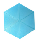
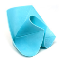
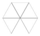
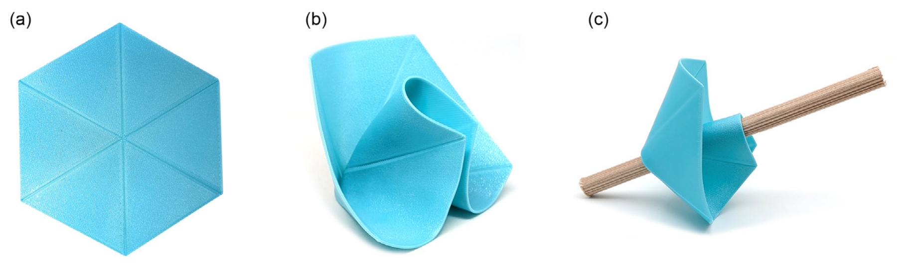
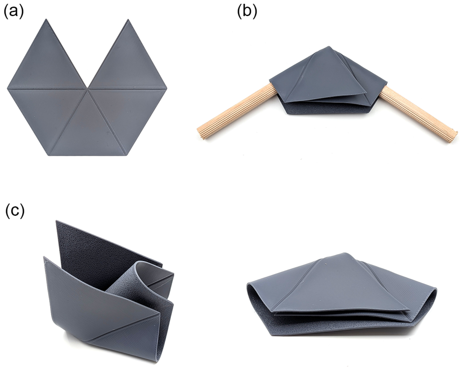
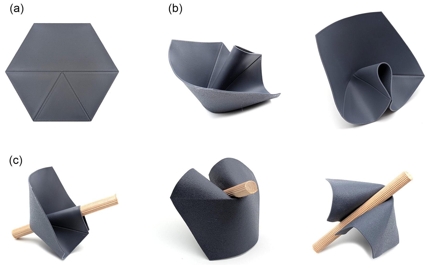
Model 11 introduces the hexagonal segmentation principle. Figure 12 shows the segmented hexagonal flat pattern and the resulting three-point cylindrical support condition. The flat hexagon is divided into six equilateral triangular segments by crease lines radiating from the center. Depressing two adjacent segments mechanically elevates an opposing segment through geometric coupling, producing a three-point cylindrical support condition. In this model, gripping behavior is generated by segment-to-segment interaction rather than by three continuous fingers bending inward. Not every panel serves as a direct contact surface; some segments act indirectly by enabling or stabilizing the gripping response of adjacent panels.

3.2.2. Model 12, Surface Continuity

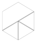
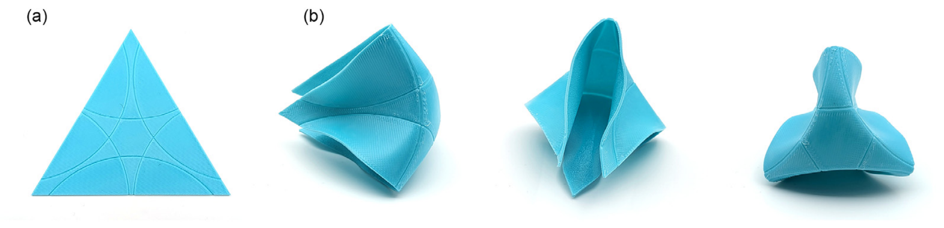
Model 12 tests the effect of reducing internal subdivision lines within the hexagonal flat pattern. Unlike Model 11, which divides the hexagon into a fuller set of triangular panel subdivisions, Model 12 retains only selected central crease lines as primary fold encoders while removing secondary subdivision lines. Figure 13 shows the simplified flat pattern and the resulting smoother activated surface. The formal quality improves substantially: the activated form reads as a smoother, more continuous surface rather than a fully faceted polygon assembly, while the cylindrical gripping behavior is preserved. The model therefore suggests a form-economy principle: reducing non-essential fold-line information can improve formal continuity without eliminating the functional segmentation required for grip.

3.2.3. Model 13, Material Extension and Guided Approach

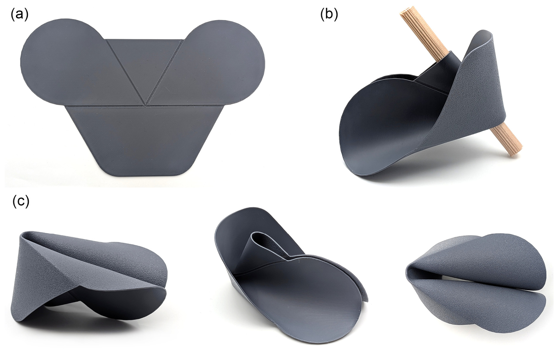
Model 13 extends the Family B wrapping logic by adding rounded lateral extensions to the flat pattern. Figure 14 shows the extended flat pattern and the resulting activated form, including cylindrical grasping demonstrations. After thermal forming, these extensions develop into broad curved surfaces positioned before and around the central grip zone. Rather than functioning only as contact surfaces after grasping, these regions create an approach geometry that can receive and guide a cylindrical object toward the gripping channel.
This guided-approach behavior was not specified as an initial design target. It emerged from the formal extension of material in the flat pattern and became evident when the activated prototype was examined with cylindrical objects. Objects introduced slightly off-center could be guided into the grip zone rather than simply meeting a hard boundary or being deflected away. The model therefore suggests that adaptivity in this family is not limited to compliance during grasping contact; it can also be shaped by the geometry that precedes the grip zone. In this sense, the guided approach is treated as a qualitative functional property in which the activated geometry receives or directs an object toward the grip zone before full contact is established.

3.2.4. Model 14, Extended Guide Fins

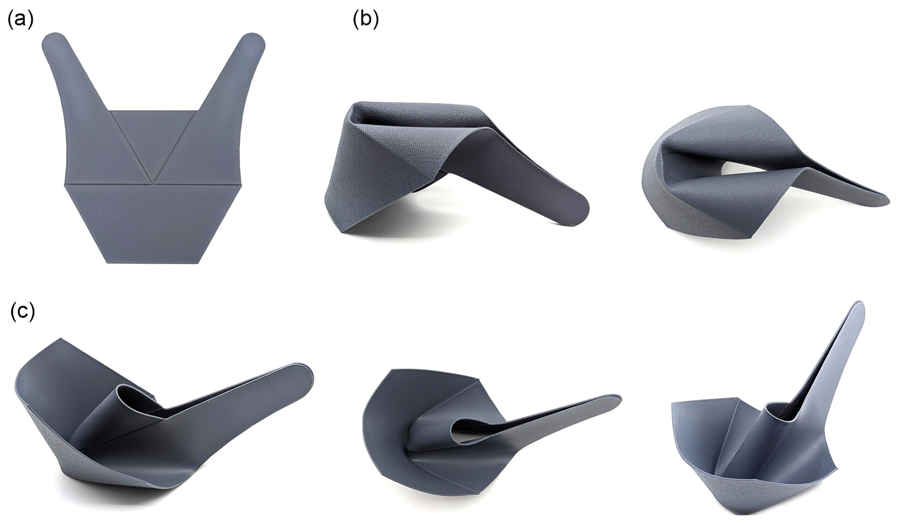
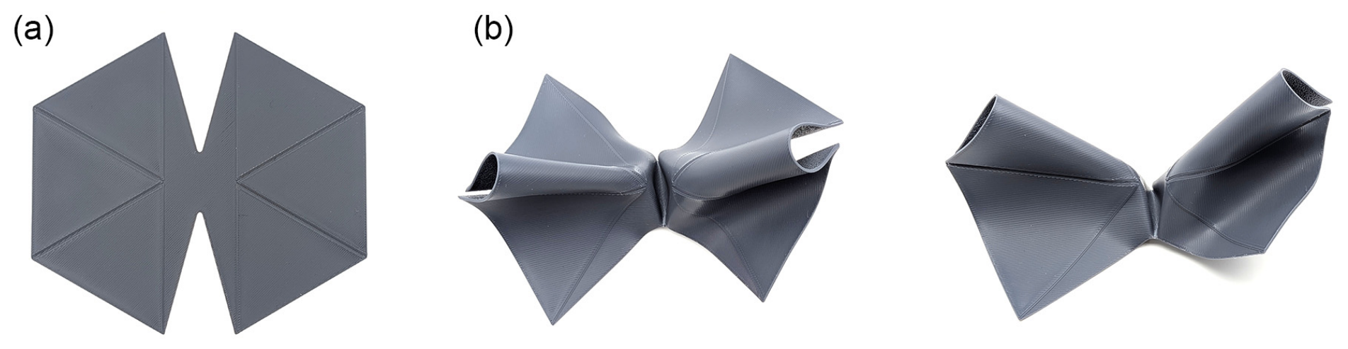
Model 14 extends the lateral guide fins introduced in Model 13. Figure 15 shows the flat pattern with elongated fins and the resulting activated form. After thermal forming, the model develops a pronounced scoop-like geometry, in which the extended surfaces define a longer and more directional approach path toward the grip channel. Compared with Model 13, the guide zone becomes visually and functionally dominant, while the effective grip aperture becomes narrower.
This model clarifies a trade-off within the guided-wrapping typology: extending the guide fins can strengthen the receiving and guiding character of the form, but it may also reduce the available opening through which an object enters the grip zone. The elongated fins also suggest a secondary role as a potential interface or attachment zone for integration into a larger system, although this remains an application direction rather than a tested function in the present study.

3.2.5. Model 15, Bilateral Extension

Model 15 extends the Family B wrapping logic toward broader and multi-directional cylindrical gripping configurations. Models 15–17 form a short developmental sequence in which bilateral extension, central subtraction, and modular repetition are tested as alternative strategies for expanding the gripping function.
Model 15 introduces a bilateral extension of the Family B wrapping geometry. The flat pattern expands the original single-cylinder logic to both sides of the central region, creating a form that can engage cylindrical objects from more than one direction. Figure 16 shows the flat pattern, activated form, and two-sided cylindrical gripping demonstrations. After thermal forming, the model produces two opposing wrapping regions, each capable of receiving or holding a cylindrical object. This expands the functional range of the Family B typology by showing how a single continuous flat pattern can generate more than one cylindrical gripping orientation.

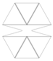
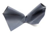
3.2.6. Model 16, Central Subtraction and Symmetry Recovery

Model 16 attempts to resolve the bilateral expansion of Model 15 through central material subtraction. Figure 17 shows the flat pattern and activated forms. The subtraction creates a clearer separation between the two sides and restores a stronger bilateral symmetry in the flat pattern, which also improves the visual balance of the activated form.
However, this intervention introduces a clear structural weakness at the center, precisely where the two gripping halves must remain connected during gripping. As a result, the model produces a less structurally robust gripping configuration, in which the formal gain in openness and symmetry is offset by a weakened central connection. Model 16 therefore reinforces the subtraction-location principle: material removal may improve visual clarity and formal articulation, but when placed within a critical structural zone it can undermine the continuity required for effective grip.

3.2.7. Model 17, Modular Dual-Cylinder Resolution

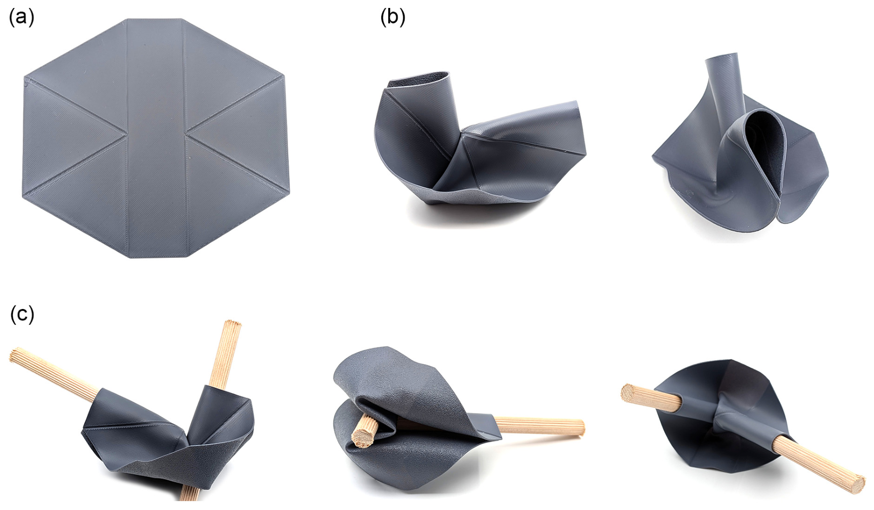
Model 17 resolves the bilateral gripping exploration by abandoning the attempt to stretch a single continuous morphology into a broader wrapping form. Instead, each side is treated as a repeated functional unit, drawing on the segmentation logic established earlier in Family B. Figure 18 shows the flat pattern, activated form, and representative dual-cylinder gripping scenarios.
After thermal forming, the model develops two opposing cylindrical gripping regions, each capable of receiving and holding a cylindrical object. Compared with Models 15 and 16, the resulting form is more coherent, with a clearer functional separation between the two gripping sides and without the weakened central subtraction zone introduced in Model 16. The progression from Models 15 and 16 to Model 17 therefore suggests a broader principle: more complex gripping functions may be achieved more effectively by repeating complete functional units than by extending or perforating a single continuous form.

3.3. Cross-Prototype Synthesis

Table 2 synthesizes the prototype catalogue across common comparative dimensions, including flat-pattern operation, activated and gripping outcome, limitation or trade-off, and local design insight. It provides an evidentiary bridge between the individual prototype descriptions and the morphological design principles developed in the Discussion section. Rather than treating the prototypes as separate examples, the synthesis identifies repeated form–behavior relationships across the catalogue and provides the basis for the design principles discussed below.

4. Discussion

The prototype catalogue developed in this study establishes a morphology-first way of reasoning about thermally formed adaptive grippers. It shows that flat-pattern decisions can encode grasp typology, organize functional roles, shape approach geometry, preserve or weaken structural continuity, and support the synthesis of more resolved gripper configurations across a family lineage. These findings position the flat pattern not as a fabrication intermediate, but as an active design space in which gripping behavior is planned before thermal forming.
The main contribution of the work is therefore broader than any single gripper configuration. The following discussion develops this contribution through morphological design principles, then considers how they reshape the relation between geometry, application, design space, and future development.

4.1. Design Principles Emerging from the Gripper Families

The prototype catalogue provides a basis for extracting transferable morphological design principles for thermally formed adaptive grippers. These principles articulate recurring form–behavior relationships grounded in the physical prototype lineage, rather than quantitative performance metrics. They operate at different levels of design decision-making, from the selection of a grasp typology to the synthesis of more resolved configurations across a family lineage.
More local observations, including fold direction, curve completeness, groove economy, and subtraction location, are retained as specific design insights within the broader principles below. They provide practical guidance at the level of individual flat-pattern decisions, while the broader principles organize these insights into a transferable design framework.
Table 3 summarizes the seven morphological design principles derived from the prototype catalogue and links each principle to its core flat-pattern logic, activated or gripping consequence, and supporting models.

4.1.1. Principle 1: Typological Encoding. Grasp Typology Is Encoded Before Forming

The most consequential difference between the two families is not a local geometric detail but a fundamental grasp logic encoded in the flat state. Family A encodes grasp by convergence: three curved elements oriented to close inward around a central point. Family B encodes grasp by wrapping and channeling: a surface organized to conform to a cylindrical axis and guide objects along it. These are not two variations of the same gripper, but two distinct grasp typologies established before thermal forming begins.
The practical implication is that the first design question for a thermally formed gripper should not concern finger geometry or surface curvature alone. It should concern the intended grasp logic: radial convergence, axial wrapping, guided approach, or some combination of these. Once this typological direction is encoded in the flat pattern, subsequent formal decisions are made within the design space it establishes.

4.1.2. Principle 2: Functional Role Distribution. A Gripper Functions as a Distribution of Roles, Not as a Single Shape

The most resolved grippers in both families are those in which distinct regions of the geometry perform distinct functions. In Model 9, nearly every part of the surface participates in a continuous grip system. In Models 11 and 12, certain segments generate the gripping response while others provide structural resistance. In Models 13 and 14, a distinct zone of material precedes the grip zone and performs approach guidance. In Model 14, the elongated fins also suggest a possible fourth role: an interface or attachment zone for integration into a larger system.
This suggests an organizing framework for flat-pattern design structured around four functional zones: (1) a grip zone, where contact and holding occur; (2) a guide zone, where incoming objects are received and guided toward the grip zone; (3) a structural zone, where geometric integrity is maintained during gripping; and (4) an interface zone, where the gripper may connect to a larger system. Making the boundaries between these zones explicit in the flat state clarifies the functional logic of the three-dimensional form that results.

4.1.3. Principle 3: Pre-Contact Adaptivity. Adaptive Gripping Begins Before Contact

Model 13 demonstrates that adaptivity in a thermally formed gripper is not limited to compliance at the moment of contact. The curved anterior surfaces produced by extending the lateral flat-pattern segments can receive off-center cylindrical objects and guide them toward the grip channel before stable gripping contact is established. Rather than depending only on accurate object placement, the gripper geometry participates in shaping the approach path. This behavior was not specified as an initial design target; it emerged from a formal decision in the flat state.
This extends the design space substantially. Approach geometry, the shape of the space through which an object travels before reaching the grip zone, is a designable property of the flat pattern. Relevant parameters include entry geometry, defined by the profile of the anterior surfaces; potential tolerance to off-center placement; and self-centering tendency, namely whether the geometry tends to guide objects toward the central axis. Model 14 amplifies the guide zone at the cost of reduced grip aperture, demonstrating a trade-off between approach guidance and the available opening through which an object enters the grip zone. This trade-off can be adjusted by varying the length and geometry of the guide fins in the flat state.

4.1.4. Principle 4: Continuous Geometry, Continuous Contact. Geometric Continuity Produces Reliable Contact

The progression from Model 1 to Model 5 to Model 9 traces a consistent formal logic: as the curved fold-line geometry of the flat pattern becomes more complete and continuous, the contact surfaces of the activated gripper become smoother, more controlled, and more capable of establishing distributed contact across a range of object geometries. Model 1 uses arc segments that terminate at polygon edges, producing terminal spikes that create irregular contact conditions. Model 5 completes the ellipse geometry, eliminating the terminal spike artifacts. Model 9 inscribes tangent circles, producing surfaces that transition between fingers without interruption.
The principle generalizes beyond curve completeness. Discontinuities in the flat pattern, including abrupt terminations, sharp corners in fold lines, and interrupted curves, can translate into local distortions in the activated form. Continuous geometry, particularly closed curves and tangent transitions, produces contact surfaces that are more geometrically controlled and predictable. For a gripper intended to operate without sensory feedback, contact reliability becomes, at least in part, a property of flat-pattern design.

4.1.5. Principle 5: Preserving Structural Continuity. Gripping Depends on Continuous Structural Regions

Models 2(1B), 3, and 16 each expose the same design risk from different directions: material is removed from a region that contributes to structural continuity, and the gripper becomes less able to maintain its form during gripping contact. Every gripper includes structurally continuous gripping regions: regions that preserve the geometry of the grip and help maintain the activated form during use. Interventions that compromise these regions can degrade gripping behavior. The issue in these models is not merely reduced performance; it is a loss of the structural continuity on which gripping depends.
Model 17 resolves the bilateral grip problem that Model 16 could not solve, not through a local repair but through structural reorganization: each half of the gripper is reconstituted as an independently complete segmented unit, with its own structurally continuous gripping regions preserved. This demonstrates the positive formulation of the principle: when a gripper must take on a more complex function, a more effective response may be to compose independent functional units that each preserve their own integrity, rather than modifying an existing structural configuration.

4.1.6. Principle 6: Modular Functional Multiplication. Complex Functions Can Be Expanded by Repeating Complete Functional Units

The comparison between Models 15, 16, and 17 suggests a principle for expanding the gripper’s morphological function. Model 15 extends a single continuous wrapping morphology to create two-sided cylindrical gripping orientations. Model 16 introduces central subtraction in an attempt to clarify the bilateral structure, but this creates a weakened central connection. Model 17 resolves the expansion differently: instead of stretching or perforating one continuous morphology, it repeats complete functional units, each preserving its own structural integrity. The result is a more coherent dual-cylinder gripping configuration.
The principle follows: when a gripper must multiply its function, the expansion may be more effectively achieved by repeating complete functional units than by stretching or perforating an existing one. The present lineage suggests that multi-object or multi-directional gripping can be developed as a composition of complete functional units rather than as an enlargement of a single-object morphology. The flat-pattern design language accommodates this directly: independent functional units can be composed in the flat state and activated as related but structurally coherent units in the three-dimensional form.

4.1.7. Principle 7: Morphological Synthesis. The Most Resolved Grippers Emerge from Synthesis, Not from Isolated Improvement

Model 9 provides a central example of how the family-based methodology can generate outcomes through cumulative morphological synthesis rather than direct specification or parameter optimization. It was not designed toward a predefined target form, but synthesized from three insights accumulated across earlier models: the ellipse-completion principle from Model 5, the spatial logic of open-stance edge-directed folding from Model 7, and the groove economy and compound fold-line logic developed through Model 8. No single one of those models produces the outcome achieved by Model 9; the resolved gripper emerges from their combination.
Model 17 offers a second example. The bilateral gripping exploration developed through Models 15 and 16 is resolved through the application of the segmentation principle established in Model 11. This demonstrates that the methodology does not treat each prototype as an isolated endpoint, but as part of an accumulating body of formal knowledge. Models that succeed, expose limitations, or reveal unresolved trade-offs all contribute to the pool of extractable knowledge from which later syntheses can draw. This is the central value of practice-based morphological research as a design method: knowledge accumulates through the lineage, and that accumulated knowledge becomes the productive resource from which more resolved outcomes are generated.

4.2. Geometry Determines Behavior, Not Application

The principles proposed in Section 4.1 position flat-pattern geometry as a generative tool for exploring possible gripping behaviors. Rather than linking each geometry to a single predefined use, the methodology allows a gripper form to be understood through its behavioral envelope: the range of object types, approach conditions, and gripping situations it can support.
Model 9 demonstrates this expanded potential. The same gripper geometry can accommodate both spherical and cylindrical objects, indicating that a single flat-pattern logic may support more than one grasping scenario. Model 13 offers a related example: the extension of material in the flat pattern generated a guided-approach behavior that became evident when cylindrical objects were introduced to the activated form. In this sense, geometry helps reveal possible applications by shaping the behaviors available to the gripper.

4.3. The Design Space as a Continuum

The two families represent distinct grasp typologies, but the boundary between them is not purely taxonomic. It is shaped by formal emphasis: convergence, wrapping, surface continuity, and approach guidance can appear in different combinations across the prototype lineage. Family A models at the wider or more laterally spreading end of the range, particularly Models 7 and 10(1A), begin to approach aspects of the cylindrical wrap-around character developed more explicitly in Family B. Conversely, Family B models with smoother activated surfaces, particularly Models 12 and 13, exhibit a degree of surface continuity that resonates with the refined finger geometry of advanced Family A models.
The design space explored here is therefore better understood as a continuum than as a set of discrete categories. Different flat-pattern strategies can produce overlapping functional tendencies, allowing designers to move between convergence-based gripping, cylindrical wrapping, guided approach, and surface continuity according to the interaction condition being explored.

4.4. Potential Application Domains

Because the grippers operate passively after thermal forming, their potential application range includes both robotic and non-robotic gripping contexts, including passive end-effectors, holding devices, fixtures, object supports, customized gripping aids, and simple assistive tools. Family A models with a vertical stance, such as Models 6 and 9, suggest potential for top-down gripping scenarios. Family B models with guided-approach geometry, such as Models 13 and 14, may support lateral approach conditions in which precise object alignment cannot be assumed. Model 9 also suggests potential as a passive grip-assistance concept for users with limited hand dexterity, since its gripping behavior does not require active actuation during use.
The two families differ in the range of object geometries they appear to support. Model 9 demonstrates that a convergence-based Family A gripper can accommodate both spherical and cylindrical objects, whereas Family B is oriented more specifically toward cylindrical grasping and guided approach. Modular repetition, as demonstrated by Model 17, suggests a route toward multi-object or elongated workpieces. More broadly, the fabrication paradigm supports customization: flat-pattern geometry can be modified before thermal forming to adjust grasp typology, guide geometry, aperture, or modular repetition. In this sense, the design principles provide a planning vocabulary for matching geometry to interaction conditions.

4.5. Comparison with Existing Approaches and Limitations

The main distinction of the present work lies in its morphology-first orientation. As discussed in the Introduction, many origami-inspired gripper studies develop flat-pattern geometry in relation to a predefined target motion, configuration, or grasping task. In contrast, the present study begins with flat-pattern composition and examines the three-dimensional gripping behaviors that emerge from it. Here, the flat pattern is treated as the starting point of design exploration and as the source from which transferable morphological principles are extracted.
The grippers also differ from actuator-based soft gripper approaches, in which gripping commonly depends on pneumatic, motorized, or otherwise active actuation during use. In the present study, thermal forming is used as a one-time fabrication step, after which the formed geometry provides passive gripping behavior during use.
The design-oriented scope of the study defines the boundary of its contribution. The prototypes were examined qualitatively in terms of morphology and functional behavior, rather than evaluated as optimized engineering devices. This allows the study to identify transferable form–behavior principles, while leaving application-specific performance validation to future work. The study does not include quantitative gripping-force measurements, systematic mechanical characterization, or long-term shape-retention testing. All prototypes were produced from commercial PLA+ filament and were evaluated primarily through morphological and qualitative observational criteria. Future studies may extend the morphological catalogue to additional flat-pattern families, object geometries, and approach conditions. A systematic study of guided-approach geometry would be especially useful for transforming the observed pre-contact guidance behavior into a more fully designable property. Subsequent engineering studies may also evaluate selected prototypes in terms of success rate over repeated trials, maximum object weight held, object-diameter range, force envelopes, durability, and repeatability when application-specific validation is required. As part of the practice-based exploration, forming was carried out manually in order to allow iterative adjustment of each flat pattern into its activated geometry. This approach is appropriate for morphological exploration, but it may introduce some variability in local curvature and final geometry. Future engineering validation may examine selected configurations using controlled forming fixtures and quantitative mechanical testing.

5. Conclusions

This study demonstrates the value of treating the flat two-dimensional print pattern as a primary design variable for thermally formed FDM adaptive grippers, based on a systematic physical exploration of 18 prototypes organized into two morphological families.
Family A showed how convergence-based gripping can be encoded through flat-pattern decisions that shape grasp typology, spatial orientation, surface continuity, and contact behavior before forming. Family B showed how a different flat-pattern logic can produce cylindrical wrapping and guided pre-contact approach, demonstrating that passive morphological adaptivity can begin before full gripping contact is established. Together, the two families suggest that thermally formed gripper design is not best understood as a set of discrete categories, but as a continuum of morphological possibilities.
The study proposed seven morphological design principles addressing typological encoding, functional role distribution, pre-contact adaptivity, geometric continuity, preservation of structural continuity, modular functional multiplication, and morphological synthesis. These principles are grounded in physical evidence across the prototype catalogue and are intended as transferable planning knowledge for designers working with thermally formed FDM grippers.
Beyond the individual principles, the study also shows that flat-pattern geometry can define a behavioral envelope rather than a single predetermined application. The same geometric logic may support different object types, approach conditions, and gripping scenarios, while controlled variation in the flat pattern allows designers to move between convergence-based gripping, cylindrical wrapping, guided approach, and modular repetition. Because gripping behavior is embedded in the thermally formed geometry rather than generated by active actuation during use, the approach may be relevant not only to robotic end-effectors but also to passive holding, support, fixture, and assistive contexts.
Through the prototype lineage, the methodology builds a cumulative vocabulary of flat-pattern operations and their three-dimensional consequences. Each model contributes to this vocabulary by resolving a formal problem, extending a gripping possibility, or revealing a design trade-off. The flat two-dimensional print pattern is therefore not merely a manufacturing intermediate; it is a design space in which gripping behavior is organized before forming begins.

Author Contributions

Conceptualization, A.S.; methodology, A.S.; investigation, A.S. and Z.S.; validation, A.S. and Z.S.; formal analysis, A.S.; resources, A.S.; data curation, A.S. and Z.S.; writing—original draft preparation, A.S.; writing—review and editing, A.S.; visualization, A.S. and Z.S.; supervision, A.S.; project administration, A.S. All authors have read and agreed to the published version of the manuscript.

Funding

This work was supported by an internal research grant from SCE—Shamoon College of Engineering, grant number YR-02-2024-D3. The APC was funded by an institutional fund allocated to the corresponding author by SCE.

Institutional Review Board Statement

Not applicable.

Informed Consent Statement

Not applicable.

Data Availability Statement

The data supporting the findings of this study are presented within the article, including prototype photographs, flat-pattern drawings, activated forms, and the morphological catalogue. Additional design documentation related to selected prototypes may be made available by the corresponding author upon reasonable request, subject to practical file availability and intellectual property considerations.

Conflicts of Interest

The authors declare no conflicts of interest.

Abbreviations

The following abbreviations are used in this manuscript:
FDMFused Deposition Modeling
PLAPolylactic acid
PLA+Commercial modified PLA filament
4DFour-dimensional

Appendix A. Visual Prototype Catalogue

Table A1. Visual catalogue of the prototype lineage, showing the flat-pattern drawing, flat printed prototype, and activated form for each model.
ModelFlat-Pattern DrawingFlat Printed PrototypeActivated Form
FAMILY A: Three-finger radial typology
M1Designs 10 00075 i001Designs 10 00075 i002Designs 10 00075 i003
M2(1B)Designs 10 00075 i004Designs 10 00075 i005Designs 10 00075 i006
M3Designs 10 00075 i007Designs 10 00075 i008Designs 10 00075 i009
M4(2A)Designs 10 00075 i010Designs 10 00075 i011Designs 10 00075 i012
M5Designs 10 00075 i013Designs 10 00075 i014Designs 10 00075 i015
M6Designs 10 00075 i016Designs 10 00075 i017Designs 10 00075 i018
M7Designs 10 00075 i019Designs 10 00075 i020Designs 10 00075 i021
M8Designs 10 00075 i022Designs 10 00075 i023Designs 10 00075 i024
M10(1A)Designs 10 00075 i025Designs 10 00075 i026Designs 10 00075 i027
M10(1A.1)Designs 10 00075 i028Designs 10 00075 i029Designs 10 00075 i030
M9Designs 10 00075 i031Designs 10 00075 i032Designs 10 00075 i033
FAMILY B: Cylindrical grasp with guided-approach geometry
M11Designs 10 00075 i034Designs 10 00075 i035Designs 10 00075 i036
M12Designs 10 00075 i037Designs 10 00075 i038Designs 10 00075 i039
M13Designs 10 00075 i040Designs 10 00075 i041Designs 10 00075 i042
M14Designs 10 00075 i043Designs 10 00075 i044Designs 10 00075 i045
M15Designs 10 00075 i046Designs 10 00075 i047Designs 10 00075 i048
M16Designs 10 00075 i049Designs 10 00075 i050Designs 10 00075 i051
M17Designs 10 00075 i052Designs 10 00075 i053Designs 10 00075 i054

References

  1. Shintake, J.; Cacucciolo, V.; Floreano, D.; Shea, H. Soft Robotic Grippers. Adv. Mater. 2018, 30, 1707035. [Google Scholar] [CrossRef] [Scilit] [PubMed]
  2. Rus, D.; Tolley, M.T. Design, Fabrication and Control of Soft Robots. Nature 2015, 521, 467–475. [Google Scholar] [CrossRef] [Scilit] [PubMed]
  3. Deimel, R.; Brock, O. A Novel Type of Compliant and Underactuated Robotic Hand for Dexterous Grasping. Int. J. Robot. Res. 2016, 35, 161–185. [Google Scholar] [CrossRef] [Scilit]
  4. Cao, H.; Zhou, J.; Chen, K.; He, Q.; Dou, Q.; Liu, Y.-H. Design and Optimization of an Origami Gripper for Versatile Grasping and Manipulation. Adv. Intell. Syst. 2024, 6, 2400271. [Google Scholar] [CrossRef] [Scilit]
  5. Tibbits, S. 4D Printing: Multi-Material Shape Change. Archit. Des. 2014, 84, 116–121. [Google Scholar] [CrossRef] [Scilit]
  6. Momeni, F.; Liu, X.; Ni, J. A Review of 4D Printing. Mater. Des. 2017, 122, 42–79. [Google Scholar] [CrossRef] [Scilit]
  7. Vaughan, L. Practice-Based Design Research; Bloomsbury Publishing: London, UK, 2017; ISBN 978-1-4742-6782-3. [Google Scholar]
  8. Zimmerman, J.; Forlizzi, J.; Evenson, S. Research through Design as a Method for Interaction Design Research in HCI. In Proceedings of the SIGCHI Conference on Human Factors in Computing Systems; Association for Computing Machinery: New York, NY, USA, 2007; pp. 493–502. [Google Scholar] [CrossRef] [Scilit]
  9. Meloni, M.; Cai, J.; Zhang, Q.; Sang-Hoon Lee, D.; Li, M.; Ma, R.; Parashkevov, T.E.; Feng, J. Engineering Origami: A Comprehensive Review of Recent Applications, Design Methods, and Tools. Adv. Sci. 2021, 8, 2000636. [Google Scholar] [CrossRef] [Scilit]
  10. Yasuda, H.; Johnson, K.; Arroyos, V.; Yamaguchi, K.; Raney, J.R.; Yang, J. Leaf-Like Origami with Bistability for Self-Adaptive Grasping Motions. Soft Robot. 2022, 9, 938–947. [Google Scholar] [CrossRef] [Scilit] [PubMed]
  11. Chan, M.C.; Scharff, R.B.N. Passive Adaptive Grippers: A Mini-Review. Front. Robot. AI 2026, 13, 1747157. [Google Scholar] [CrossRef] [Scilit] [PubMed]
  12. Gladman, A.S.; Matsumoto, E.A.; Nuzzo, R.G.; Mahadevan, L.; Lewis, J.A. Biomimetic 4D Printing. Nat. Mater. 2016, 15, 413–418. [Google Scholar] [CrossRef] [Scilit] [PubMed]
  13. Lee, A.Y.; An, J.; Chua, C.K. Two-Way 4D Printing: A Review on the Reversibility of 3D-Printed Shape Memory Materials. Engineering 2017, 3, 663–674. [Google Scholar] [CrossRef] [Scilit]
  14. Bonetti, L.; Natali, D.; Pandini, S.; Messori, M.; Toselli, M.; Scalet, G. 4D Printing of Semi-Crystalline Crosslinked Polymer Networks with Two-Way Shape-Memory Effect. Mater. Des. 2024, 238, 112725. [Google Scholar] [CrossRef] [Scilit]
  15. van Manen, T.; Janbaz, S.; Zadpoor, A.A. Programming 2D/3D Shape-Shifting with Hobbyist 3D Printers. Mater. Horiz. 2017, 4, 1064–1069. [Google Scholar] [CrossRef] [Scilit] [PubMed]
  16. van Manen, T.; Janbaz, S.; Zadpoor, A.A. Programming the Shape-Shifting of Flat Soft Matter. Mater. Today 2018, 21, 144–163. [Google Scholar] [CrossRef] [Scilit]
  17. Nojoomi, A.; Jeon, J.; Yum, K. 2D Material Programming for 3D Shaping. Nat. Commun. 2021, 12, 603. [Google Scholar] [CrossRef] [Scilit] [PubMed]
  18. Saptaji, K.; Rochmad, C.O.; Juniasih, O.A.; Sunnardianto, G.K.; Triawan, F.; Ramadhan, A.I.; Azhari, A. Enhancing Shape-Recovery Ratio of 4D Printed Polylactic Acid (PLA) Structures through Processing Parameter Optimization. Prog. Addit. Manuf. 2024, 9, 1869–1881. [Google Scholar] [CrossRef] [Scilit]
  19. Yuan, C.; Lu, T.; Wang, T.J. Mechanics-Based Design Strategies for 4D Printing: A Review. Forces Mech. 2022, 7, 100081. [Google Scholar] [CrossRef] [Scilit]
  20. Demoly, F.; Dunn, M.L.; Wood, K.L.; Qi, H.J.; André, J.-C. The Status, Barriers, Challenges, and Future in Design for 4D Printing. Mater. Des. 2021, 212, 110193. [Google Scholar] [CrossRef] [Scilit]
  21. Liu, C.; Wohlever, S.J.; Ou, M.B.; Padir, T.; Felton, S.M. Shake and Take: Fast Transformation of an Origami Gripper. IEEE Trans. Robot. 2022, 38, 491–506. [Google Scholar] [CrossRef] [Scilit]
  22. Hou, N.; Wu, M.; Zhao, Q.; Tang, Z.; Wang, K.; Xu, X.; Zheng, X.; Xie, G. Reticular Origami Soft Robotic Gripper for Shape-Adaptive and Bistable Rapid Grasping. Soft Robot. 2024, 11, 550–560. [Google Scholar] [CrossRef] [Scilit] [PubMed]
  23. Hekkert, P.; van Dijk, M. Vision in Design: A Guidebook for Innovators; BIS Publishers: Amsterdam, The Netherlands, 2011; ISBN 978-90-6369-205-6. [Google Scholar]
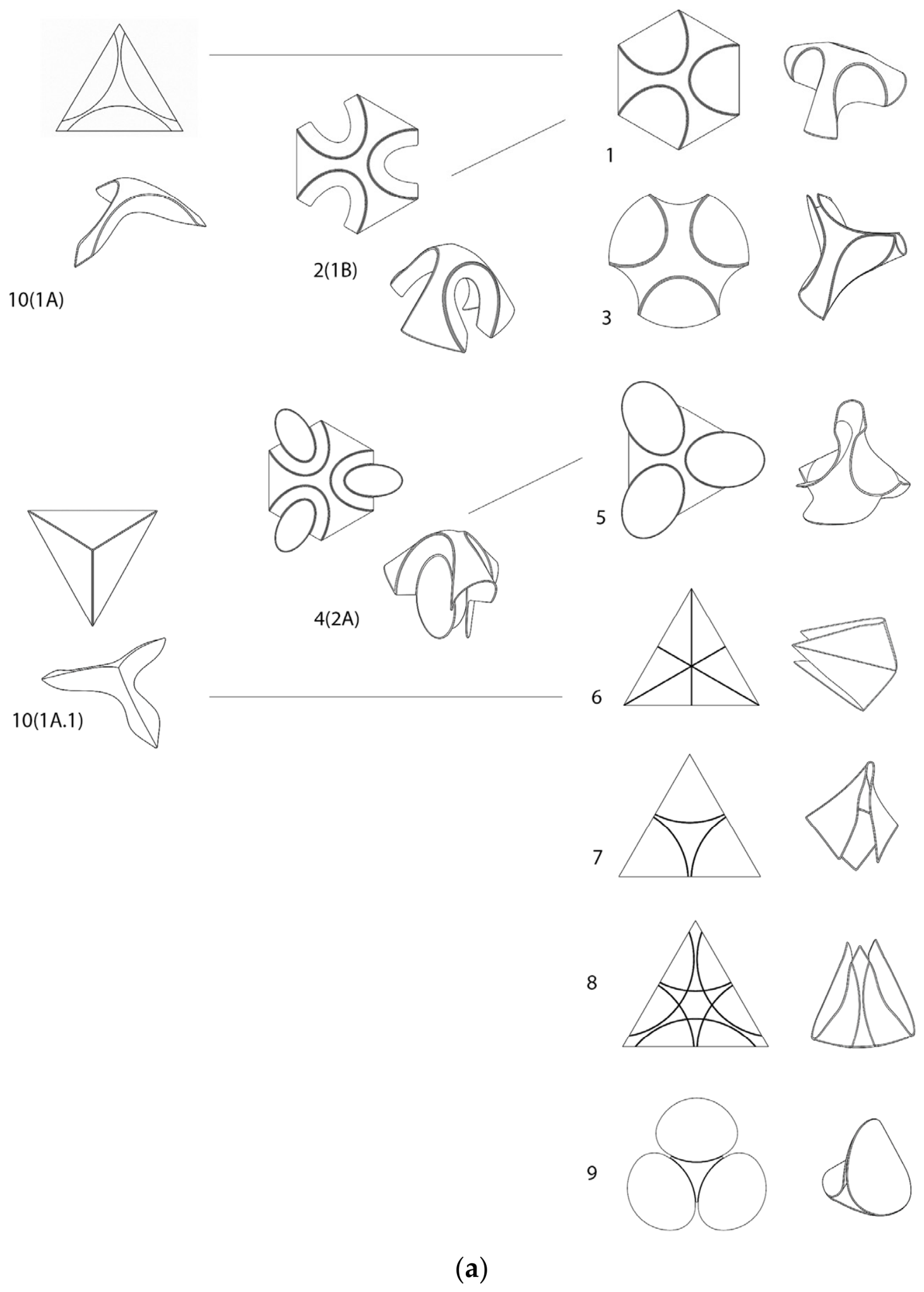
Figure 1. (a). Lineage diagram of Family A, showing flat pattern origins, activated forms, and derivation relationships. (b). Lineage diagram of Family B, showing flat pattern origins, activated forms, and derivation relationships.
Designs 10 00075 g001aDesigns 10 00075 g001b
Figure 2. Physical catalogue used during the practice-based morphological exploration, showing flat patterns and activated prototypes arranged for comparison across the design lineage.
Designs 10 00075 g002
Figure 3. Representative derivation paths in Family A. Upper row: transition from Model 1 (black) to Model 5 (magenta). Lower row: transition from Model 2(1B) (black) to Model 4(2A) (magenta).
Designs 10 00075 g003
Figure 4. Model 1: (a) flat pattern; (b) activated form views; and (c) ball-gripping demonstrations.
Designs 10 00075 g004
Figure 5. Body-subtraction variants: (a) Model 3; (b) Model 2(1B). Each panel shows the flat printed prototype, flat-pattern drawing, and activated form views, illustrating open formal compositions and reduced gripping support.
Designs 10 00075 g005
Figure 6. Model 4(2A): (a) flat pattern; (b) representative ball-gripping demonstration; and (c) activated form views.
Designs 10 00075 g006
Figure 7. Model 5: (a) flat pattern; (b) representative ball-gripping demonstration; and (c) activated form views.
Designs 10 00075 g007
Figure 8. Models 6 and 7: (a) Model 6 flat pattern; (b) Model 6 activated form views; (c) Model 7 flat pattern; (d) Model 7 activated form; and (e) representative ball-gripping demonstration of Model 7.
Designs 10 00075 g008
Figure 9. Model 8: triangular flat pattern (a) and activated gripper form shown from three viewing angles (b), demonstrating the effect of groove density and compound fold-line geometry on formal flow.
Designs 10 00075 g009
Figure 10. Model 10 branch: Model 10(1A.1) (a) and Model 10(1A) (b), showing flat patterns, activated forms, and gripping demonstrations, with vertical and lateral outcomes resulting from different fold-direction encodings.
Designs 10 00075 g010
Figure 11. Model 9: (a) flat pattern; (b) activated form from multiple views; (c) representative gripping demonstrations with spherical and cylindrical objects in different orientations.
Designs 10 00075 g011
Figure 12. Model 11: segmented hexagonal flat pattern (a), activated form (b), and cylindrical gripping demonstration (c), demonstrating a three-point cylindrical support condition.
Designs 10 00075 g012
Figure 13. Model 12: simplified hexagonal flat pattern with selected central crease lines retained (a), activated form with smoother surfaces (b), and cylindrical gripping demonstrations from different viewing angles (c).
Designs 10 00075 g013
Figure 14. Model 13: flat pattern with rounded lateral extensions (a), cylindrical gripping demonstration (b), and activated views showing broad guide surfaces (c).
Designs 10 00075 g014
Figure 15. Model 14: flat pattern with elongated guide fins (a), and activated views from lower (b) and upper (c) perspectives, showing a pronounced scoop-like approach geometry.
Designs 10 00075 g015
Figure 16. Model 15: bilateral extension of the Family B wrapping geometry, showing the flat pattern (a), activated form (b), and two-sided cylindrical gripping demonstrations (c).
Designs 10 00075 g016
Figure 17. Model 16: flat pattern with central material subtraction (a), and activated forms showing bilateral symmetry with a weakened central connection (b).
Designs 10 00075 g017
Figure 18. Model 17: repeated bilateral wrapping units, showing the flat pattern (a), representative dual-cylinder gripping scenario (b), and activated form variations (c).
Designs 10 00075 g018
Table 1. Fabrication and thermal-forming parameters used across the prototype catalogue.
ParameterValue/description
MaterialCommercial PLA+ filament.
PrinterBambu Lab X1 Carbon FDM desktop printer.
Nozzle diameter0.4 mm.
Layer height0.2 mm.
Sheet thickness0.8 mm.
Flat-pattern dimensionsFamily A flat patterns ranged from approximately 110 to 167 mm in the main in-plane dimensions. Family B flat patterns ranged from approximately 97 to 201 mm in the main in-plane dimensions.
InfillThe slicer infill setting was left at the default value of 15%. Due to the 0.8 mm sheet thickness and 0.2 mm layer height, the sheets consisted of four solid layers, and no internal infill region was generated in practice. The nominal infill setting therefore had no practical effect; bending behavior was governed by the fold-line/groove geometry.
Print orientationModels were printed flat on the build plate, with sheet thickness along the Z-axis.
Fold-line/groove geometryFold-line regions were produced as locally weakened groove geometries integrated into the flat pattern. Groove width was 0.8 or 2.0 mm, depending on the model, and groove depth was 0.4 mm. Groove arrangement and spacing varied according to the specific model geometry.
Thermal forming mediumHot-water immersion.
Water temperature controlWater was heated in a 1600 mL Pyrex glass container on a controlled electric hot plate (FE Fried Electric, model HP-4) and monitored with a thermometer during forming, maintaining approximately 60–70 °C.
Hot-water immersion time30–60 s, until the PLA+ sheet became pliable.
Forming methodManual forming according to the designed fold-line layout. In some cases, simple reference objects or previously formed models were used to guide curvature during cooling. No controlled mechanical forming fixture or mold was used.
Cooling protocolPassive cooling at room temperature while the formed geometry was held in place for approximately 90 s. No active cooling was used; solidification began immediately upon removal from the hot water.
Number of physical modelsMultiple physical models were produced for each design during the morphological exploration, including models used for forming, refinement, documentation, and comparison. The number of instances was not fixed as an experimental sample size.
Actuation during useNone. Thermal forming was a one-time fabrication step; after cooling, gripping behavior arose from the formed geometry itself.
Table 2. Cross-prototype synthesis of the morphological catalogue.
ModelFlat-Pattern OperationActivated Morphology/Gripping OutcomeLimitation/Trade-OffDesign Insight
M1Hexagonal base with three arc curvesThree-finger radial form; initial ball-gripping demonstrationFingertip spikes; compressed central convergenceArc curves establish the basic radial three-finger typology but create local contact artifacts.
M2(1B)Material subtraction from the central structural bodyOpen body-subtraction variant; reduced gripping supportReduced structural integrity under contactRemoving material from the structural body can improve visual openness but weakens gripping function.
M3Inverted arcs with material subtraction from the central structural bodyOpen body-subtraction variant; reduced gripping supportReduced structural integrity under contactBody subtraction confirms the functional cost of removing material from load-bearing regions.
M4(2A)Body subtraction combined with discrete finger elementsHybrid configuration; some gripping behavior recoveredReads as additive assembly rather than unified geometryFormal operations require a governing geometric logic to produce a coherent activated geometry.
M5Three complete ellipses used as fold-line geometrySmooth rounded three-finger form; spike artifacts removed; stable partial support during manual handlingLimited cylindrical gripping; large spheres may slide outClosed curves improve fingertip resolution, contact redundancy, and object-size selectivity.
M6Triangular base with corner-directed fold linesTall vertical convergent form; tested with cylindrical objectsShort converging fingers limited opening and contact; slight manual-forming deformationFold direction changes spatial orientation and object-entry behavior.
M7Triangular base with edge-directed concave arcsWide horizontal open form; received and held spherical objectsLimited cylindrical gripping; pointed ends interfere with insertion and create weak regionsFold direction can improve spherical-object reception by opening the central region.
M8Straight and curved fold lines with varied groove densityShell-like gripper; more defined contact region and clearer object supportDense grooves may diffuse deformation and reduce curvature clarityFewer, precise grooves can improve formal flow and focus contact regions.
M10(1A)Triangular base with edge-directed fold-line strategyLow horizontal form; narrow cylinders supported mainly between two facesDifficult object entry; narrow lower opening; broad short fingers reduce enclosure and gripping supportHorizontal spreading can reduce effective enclosure and object entry.
M10(1A.1)Triangular derivation with altered fold-direction encodingTaller vertical form; small spheres and narrow cylinders tested; vertical gripping observed with thicker cylinderShort fingers and pointed ends limit reception and contactVertical convergence can improve gripping relative to the horizontal variant, depending on the upper opening.
M9Three tangent circles in a triangular base, synthesizing insights from M5, M7, and M8Smooth three-finger form; stable support observed with spherical and cylindrical objectsSmall residual central voidResolved grippers can emerge from synthesizing accumulated morphological insights.
M11Hexagon segmented into six triangular panelsThree-point cylindrical gripping condition generated by coupled segment motionNot all panels serve as direct contact surfacesGripping can arise from segment-to-segment interaction rather than continuous fingers.
M12Selected central crease lines retained; secondary lines removedSmoother continuous surface; cylindrical gripping preservedLimited support for wide cylindersReducing non-essential fold lines improves continuity while preserving functional segmentation.
M13Rounded lateral extensions added to the flat patternBroad guide surfaces; off-center objects guided into grip zoneLarger, less compact flat pattern; limited wide-cylinder entryMaterial extension can create pre-contact guided approach.
M14Elongated guide finsScoop-like approach geometry; more pronounced guidance toward grip channelNarrower effective grip apertureLonger guide fins increase guidance but reduce entry opening.
M15Bilateral extension of the wrapping geometryTwo opposing wrapping regions; each can receive or hold a cylinderMore complex forming; central strip limited bending; asymmetry appearedOne continuous flat pattern can generate multiple cylindrical gripping orientations, but with higher forming complexity.
M16Central subtraction in the bilateral configurationClearer bilateral separation and visual balance; less structurally robust gripping configurationWeakened central connectionMaterial removal can clarify form but undermine continuity in critical structural zones.
M17Repetition of complete functional unitsMore coherent dual-cylinder configuration; simultaneous gripping of two cylinders demonstratedSome two-dimensional engagement; adjacent walls interfered slightly; grip remained asymmetricalComplex gripping functions can be expanded by repeating complete units while preserving the integrity of each functional unit.
Table 3. Summary of morphological design principles derived from the prototype catalogue.
Morphological Design PrincipleCore Flat-Pattern LogicActivated/Gripping ConsequenceSupporting Models
1. Typological Encoding. Grasp Logic Is Defined in the Flat StateEncode the intended grasp logic in the flat pattern, such as radial convergence, axial wrapping, guided approach, or combinations of these.Establishes the primary grasp typology before thermal forming and defines the design space within which later formal decisions are made.Family A; Family B; M1; M11–M14
2. Functional Role Distribution. A Gripper Functions as a Distribution of Roles, Not as a Single ShapeOrganize the flat pattern around distinct functional zones: grip, guide, structural, and interface zones.Produces activated grippers in which different regions perform distinct roles, including holding, guiding, structural resistance, and possible system integration.M9; M11; M12; M13; M14
3. Pre-Contact Adaptivity. Adaptive Gripping Begins Before ContactShape the approach geometry in the flat state, including entry geometry, anterior guide surfaces, and guide-fin length/geometry.Allows off-center cylindrical objects to be received and guided toward the grip channel before stable support or gripping contact is established; increasing guidance can reduce grip aperture.M13; M14
4. Continuous Geometry, Continuous Contact. Geometric Continuity Produces Reliable ContactUse complete curves, closed curves, tangent transitions, and continuous fold-line geometry rather than abrupt terminations, sharp corners, or interrupted curves.Produces smoother, more controlled, and more predictable contact surfaces; reduces local distortions and terminal spike artifacts.M1; M5; M9
5. Preserving Structural Continuity. Gripping Depends on Continuous Structural RegionsPreserve the regions that maintain the geometry of the grip and support structural continuity during use.Supports the gripper’s ability to maintain its form during gripping contact; material removal from critical regions weakens structural continuity and degrades gripping behavior.M2(1B); M3; M16; M17
6. Modular Functional Multiplication. Complex Functions Can Be Expanded by Repeating Complete Functional UnitsMultiply function by composing repeated complete functional units in the flat state rather than stretching or perforating an existing morphology.Enables multi-object or multi-directional gripping as related but structurally coherent units in the activated three-dimensional form.M15; M16; M17
7. Morphological Synthesis. The Most Resolved Grippers Emerge from Synthesis, Not from Isolated ImprovementRecombine accumulated insights from earlier prototypes into new configurations rather than optimizing a single isolated variable.Produces more resolved configurations through cumulative morphological knowledge; later models draw on successes, limitations, and trade-offs exposed earlier in the lineage.M5; M7; M8; M9; M11; M15–M17
Disclaimer/Publisher’s Note: The statements, opinions and data contained in all publications are solely those of the individual author(s) and contributor(s) and not of MDPI and/or the editor(s). MDPI and/or the editor(s) disclaim responsibility for any injury to people or property resulting from any ideas, methods, instructions or products referred to in the content.